


Abstract
Following the realization of Weyl semimetals in quantum electronic materials, classical wave analogues of Weyl materials have also been theorized and experimentally demonstrated in photonics and acoustics. Weyl points in elastic systems, however, have been a much more recent discovery. In this study, we report on the design of an elastic fully-continuum three-dimensional material that, while offering structural and load-bearing functionalities, is also capable of Weyl degeneracies and surface topologically-protected modes in a way completely analogous to its quantum mechanical counterpart. The topological characteristics of the lattice are obtained by ab initio numerical calculations without employing any further simplifications. The results clearly characterize the topological structure of the Weyl points and are in full agreement with the expectations of surface topological modes. Finally, full field numerical simulations are used to confirm the existence of surface states and to illustrate their extreme robustness towards lattice disorder and defects.
Export citation and abstract BibTeX RIS
1. Introduction
The search for novel topological states of matter has recently seen many exciting breakthroughs either in quantum or classical wave physics [1–6]. Phenomena such as the quantum Hall effect (QHE), the quantum spin Hall effect (QSHE), and the quantum valley Hall effect (QVHE) have been studied extensively and their nontrivial topological characteristics have been clearly connected to their ability to support back-scattering-immune topological edge states [1, 2]. Although the concept of topological material was discovered and developed in the field of condensed matter physics, the many conceptual and mathematical similarities between different fields of wave physics have led to the development of analogue concepts of topological materials in electromagnetic [3, 4], acoustic [5–10], and elastic [11–19] systems. Recent studies have identified the existence of the so-called Weyl semimetals as three dimensional nontrivial topological materials capable of unidirectional back-scattering-protected surface states [20].
Weyl semimetals are quantum materials whose behavior is characterized in terms of the Weyl Hamiltonian  , where νi, ki, and σi represent the components of the group velocity, momentum, and Pauli matrix, respectively. These materials can be thought of as a three-dimensional extension of two-dimensional nontrivial topological materials characterized by Dirac degeneracies such as, for example, systems exhibiting QHE, QSHE, and QVHE [1, 2]. Similar to 2D Dirac materials, Weyl semimetals possess a degenerate nodal point formed by linear intersection of two bands in the three coordinate directions of the three dimensional reciprocal space. This degenerate point, called the Weyl point, carries a nonzero topological charge which confers the material nontrivial topological properties. The charge (i.e. the integral of the Berry curvature flux in a 2D manifold enclosing the Weyl point) can have either a positive or negative sign, hence determining if the degeneracy acts as a quantized source or a sink of Berry curvature flux. The total topological charge associated with the Brillouin zone (BZ) in reciprocal space should always be zero [21], therefore indicating that Weyl points always occur in pairs of opposite charge. Nontrivial topological surface states connecting the Weyl points of opposite charge exist on the boundary of the system. Apart from topological surface states, Weyl points have also been linked to other unusual effects such as chiral anomaly [22] and quantum anomalous Hall effect [23].
Weyl points can be qualitatively interpreted as an extension of Dirac points (typical of 2D lattices) to three-dimensional lattices. However, there are some fundamental qualitative differences that have important implications on both the occurrence and robustness of these degeneracies. Dirac degeneracies are usually classified in either accidental or essential degeneracies. The accidental degeneracies occur as a result of a specific combination of either material or geometric parameters [24, 25]. Accidental degeneracies are lifted as soon as any of these parameters is slightly perturbed from its reference value. On the other hand, the existence of essential Dirac points can be guaranteed purely based on symmetry arguments. This means that lattice structures (such as, for example, graphene or graphene-like unit cells) that are capable of preserving simultaneously both parity-inversion (P) and time-reversal (T) symmetries are guaranteed to exhibit Dirac degeneracies. Such degeneracies cannot be lifted by simply perturbing either geometric or material parameters (like in the case of accidental Dirac degeneracies) but require breaking either P or T-symmetry. Once the degeneracy is lifted, the resulting bandgap is typically topologically non-trivial. While the conditions for the occurrence of Dirac degeneracies in 2D materials are clearly defined, an equivalent set of conditions for the occurrence of Weyl points cannot be easily identified. It follows that the occurrence of these 3D degeneracies cannot be guaranteed a priori exclusively based on symmetry constraints. On the other hand, we can establish a condition under which Weyl points can certainly not exist. For Weyl points, the satisfaction of P and T-symmetries impose contradicting requirements. Assuming a lattice exhibiting a Weyl degeneracy at the k high-symmetry point in reciprocal space, T-symmetry would require the topological charges at k and −k to be of the same sign, while P-symmetry would require them to be opposite. Due to these contradicting requirements, it follows that Weyl points can only be obtained in systems with broken PT-symmetry. A further consequence of this observation is that Weyl degeneracies cannot be lifted by simply breaking symmetry (as is the case of Dirac degeneracies), instead they must be annihilated by combining pair of Weyl points with opposite charges. These more stringent requirements for lifting the Weyl degeneracy are at the foundation of their higher robustness against external perturbations, compared to Dirac points. Also, following the requirements dictated by both P and T-symmetries, the minimum number of Weyl points in a BZ is 4 (2 pairs) when P-symmetry is broken and 2 (1 pair) when T-symmetry is broken [3].
Note also that, although in the current study only Weyl points with unit charge are considered, other studies [26–34] have reported systems possessing Weyl points that have higher charge. They are typically caused by the overlapping of multiple Weyl points of unit charge. Such points can be readily identified from the band structure because the bands do not intersect linearly at these points in the kx–ky plane (although they do intersect linearly along kz). Recent studies, both in photonic and phononic systems, have also reported a new kind of Weyl point labeled type-II [35–40]. The degeneracies discussed in the present study are of type-I and represent the more direct analogue to the degeneracies originally studied by Weyl in quantum mechanical systems [41].
While first theorized as the massless solution of the Dirac equation [41], Weyl fermions could be realized and experimentally demonstrated in Weyl semimetals only recently [26–29, 42–46]. The possibility of identifying classical mechanical systems serving as analogue to the Weyl semimetals has opened an intriguing and fertile topic of research spanning many areas of wave physics. As a result, non-quantum-mechanical analogues of the Weyl points were formulated both in photonic [30, 32, 36–38, 47–53] and acoustic [33, 34, 39, 54–56] metamaterial systems. Weyl points were realized and experimentally demonstrated in photonics using double-gyroid structure characterized by broken P-symmetry [47, 48]. Although capable of realizing Weyl points, the double-gyroid structure involves a complex fabrication. Simpler designs based, as an example, on woodpile photonic crystals [32, 52] or on rotated stacked rods in acoustic systems [33, 34] were also explored. A planar fabrication methodology, which outlines a step by step approach to obtain Weyl points, was also presented [30, 51].
Despite the successful implementation of Weyl points in photonic and acoustic systems, the realization of Weyl points in elastic systems has proven to be more challenging than other classical analogues. Acoustic systems support only longitudinal waves and hence are immune to wave coupling and mode conversion issues, thereby making the task of achieving complete bandgaps easier. While wave coupling and mode conversion between different polarizations occur also in photonic systems (characterized by two transverse modes), the phenomenon is still more challenging in elastic systems given the existence of three possible polarizations; two quasi-shear and one quasi-longitudinal. The quasi-longitudinal elastic mode is acoustically fast (compared to the shear modes) and it does not easily allow for a full topological bandgap (that is a bandgap affecting all modes). While this is not necessarily a problem per se, because a partial bandgap affecting only shear modes can still exhibit topological properties, it does require additional care in decoupling longitudinal and shear modes so as to avoid mode conversion from longitudinal to shear. This latter conversion might corrupt either the bandgap or the topological properties. Mode conversion can be counteracted by choosing unit cell geometries that reduces mode coupling; this condition typically imposes constraints on the out-of-plane symmetry of the unit cell. Another complexity in the realization of Weyl elastic systems is associated with fabrication capabilities. To-date, very few elastic systems have actually reported observation of Weyl points [31, 53, 57]. The study by Wang et al [31] made use of beams and thin plates with a particular geometry purposely selected to be realized by additive manufacturing. Another study by Shi et al [57] utilized a truss-like construction made of beam elements. Although elegant and simple to fabricate, these designs are discrete in nature therefore not well suited for applications where the load-bearing capabilities in presence of uniformly distributed loads play a critical role (e.g. applications to structural materials needed to carry aero- or fluid-dynamic loads). In addition, in both the above mentioned studies, the topological characteristics were obtained based on a tight-binding (TB) formulation of the Hamiltonian. This approach works well only when the fundamental lattice is composed of weakly coupled resonant elements. Further, the hopping parameters used in the TB model usually cannot be clearly connected to the actual geometric and design parameters. For strongly coupled or fully continuous systems, the TB model is no longer valid. The premise behind the TB model is that the elastic wave is strongly localized near the periodic resonant sites and only weakly coupled with neighboring ones. Hence, the entire wavefunction can be expressed as an expansion of eigenmodes on these neighboring sites, and the frequency is obtained by using a perturbation approach applied in the neighborhood of a single resonant site frequency. However, in cases involving strong coupling, presence of long-range interactions, and fully continuous systems, the inference from such perturbation approach cannot hold. We note that, although in principle one can still build an analogous TB model and obtain the parameters by matching the dispersion characteristics so as to eventually obtain the effective Hamiltonian, our recent study [18] has shown that some properties cannot be captured by such low-order approximation, and that direct numerical models are needed to accurately capture the system's behavior. Another implementation of an elastic Weyl material was based on double-gyroid structures [53]. Aside from the fabrication complexity, this design used soft matter and depended on the application of an external strain field in order to break the symmetry and obtain the Weyl points. In the same study, the authors employ a direct numerical method to evaluate the topological charge of the photonic Weyl point. The approach is based on the evaluation of a loop integral of the Berry connection. The integral that yields the topological charge is undoubtedly gauge invariant. However, due to the intrinsic phase ambiguity of the Bloch state in momentum space, the Berry connection field per se is gauge dependent.
In this regard, we propose an elastic analogue of a Weyl semimetal material based on a fully continuous and load-bearing design. Our material is inspired to sandwich composite structures [58] where the classical honeycomb core is replaced by a network of trusses that satisfies specific symmetry conditions. While the symmetry of the unit cell is analogous to the design by Xiao et al [55], their system is purely acoustic and cannot control elastic waves or, equivalently, is not a structural Weyl material.
The interest in structural Weyl materials stems from the need to complement the classical properties of conventional structural material platforms (primarily their load-bearing capability) with advanced stress wave control capabilities.
The underlying idea being that if the flow of mechanical energy through the system can be controlled and energy can be channeled to selected locations, then this energy can be efficiently extracted for either dissipation or harvesting purposes. The extraction system (e.g. damping materials or transducers) would implicitly be optimized hence requiring a minimum amount of added components, weight, and overall complexity.
More specifically, the load-carrying capacity combined with the robust topological surface states for the control of elastic waves make our design very well suited for vibration control and stress wave shielding. A variety of applications can be envisioned where this control capability could be of particular interest including vibration control in aerospace, mechanical, and naval systems. In these applications, distributed loads must be efficiently carried by the structure without compromising its integrity. At the same time, these loads inject large amount of mechanical energy that could give rise to high level responses, hence requiring efficient damping approaches. Other relevant applications include seismic damage prevention (e.g. in-ground seismic isolation mechanisms or insulating platforms), and insulating pads for heavy machinery. Applications to structure-radiated noise could also be envisioned. Note also that, once the vibrational energy is channeled, it could also be efficiently harvested for low power electronics [59, 60]. Since the Weyl points and surface states in this study are purely a result of symmetry breaking, the design can be scaled or replicated by using different materials in order to achieve the required load-bearing capacity and the target operating frequency range for each specific application. The topological surface states are also robust in the sense that as long as the symmetry requirements are met, any amounts of load or deformations in the linear regime do not affect their existence. This further supports their application as load-bearing structures.
We will also present a detailed study of the topological characteristics based on ab initio calculations, hence bypassing the limitations of TB approaches when dealing with strongly coupled systems. In our approach, the topological charge is obtained by direct numerical calculation of the surface integral of the gauge invariant Berry curvature flux on a closed manifold enclosing the Weyl point. By calculating and visualizing the Berry curvature on selective planes in momentum space, this approach also provides an intuitive picture of the topological charge (given that the Berry curvature can be considered as the flux emitted by the charge seen as a monopole source).
This paper is organized as follows: section 2 will introduce the proposed design and the corresponding dispersion properties in connection with Weyl points. Section 3 will present ab initio calculations of the topological invariant. Section 4 will focus on the dispersion behavior of a supercell and the corresponding dispersion structure, in order to determine the occurrence of surface states. Finally, section 5 will show full field simulations of the elastic Weyl material in order to illustrate the one-way, backscattering-immune nature of the surface states.
2. Synthesis of the unit cell and dispersion properties
From a general perspective, in order to develop the fundamental unit cell, we select a 2D triangular lattice (assumed in the xy-plane) and build the 3D geometry by periodically repeating this unit along the z-direction. The sandwich design contains a straight pillar located at the center of the unit cell, connecting the top and bottom skins that are essentially thin metal plates as shown in figure 1(a). The pillar is designed to take compressive and tensile loads and conceptually takes the role of a classical honeycomb core when the composite is subject to compression/tension. The metal plates are an important feature of the structural design because they allow the whole material to carry distributed pressure loads, such as those possibly arising from aero- and fluid-dynamic loads typical of many aerospace, naval, and even civil engineering applications. Note that this latter capability is in contrast with most of the elastic Weyl material designs available in the literature that are mostly based on reticular or discrete geometries with no ability to carry pressure loads. The final result is a layered 3D structure having intact P and T-symmetries. Note that, as previously mentioned, starting from a 2D triangular lattice guarantees (due to symmetry arguments) the existence of Dirac degeneracy at the high symmetry points in the kx–ky momentum space. Periodically repeating this unit in the z-direction extends the Dirac degeneracy at virtually any kz value, thereby generating a line node degeneracy [3, 51] along kz. In order to lift this three-dimensional degeneracy, P-symmetry can be broken by the proper introduction of additional structural element that do not respect inversion symmetry. For this purpose, we select slanted beam elements connecting the vertices of the hexagonal structure on two adjacent layers as shown in figure 3. The slanted nature of these beams introduces a chiral coupling, that is a preferential sense of rotation to the unit-cell that breaks the P-symmetry and all existing mirror symmetries. The most direct consequence is that the line degeneracy along kz is reduced to a point, hence giving rise to the Weyl point. Note that the slanted cylinders connecting top and bottom skins also allow carrying both bending loads and in-plane shear loads applied on the skins, hence strengthening the overall load-bearing capability.

Figure 1. (a) Schematics of the unit cell with intact P- and T-symmetry. Some characteristic dimensions are shown. The top and bottom plates are made of aluminum (transparent white) while the cylinder is made of iron (black). Periodic boundary conditions are used on the boundaries to create a 3D lattice. (b) Rendered view of a bulk piece of the 3D lattice. (c) Brillouin zone of the resulting 3D lattice in reciprocal space. Orange dashed lines mark the irreducible part of the Brillouin zone (IBZ).
Download figure:
Standard image High-resolution imageIn the following section, we first describe the geometry and the dynamic properties of the parity-preserving fundamental unit. Then, we introduce the chiral coupling and investigate its effect compared with the P-symmetric unit.
2.1. 3D lattice with intact P-symmetry: line node degeneracy
Figures 1(a) and (b) show the fundamental unit cell used to create the lattice. The cell, as mentioned earlier, is made of a vertical cylinder included between two homogeneous, hexagonal-shaped, thin plates. The cylinder has its longitudinal axis aligned with the z-direction. The cylinder is made of iron while the plates are made of aluminum. The selection of these materials was motivated by the intent of obtaining marked degeneracies at the high symmetry points in the momentum space. Clearly, several other combinations of structural materials leading to similar conditions could potentially be identified. The dimensions of the unit cell are: a = 30 mm, h0 = 2 mm, r1 = 5 mm, h1 = 20 mm, where a is the lattice constant, h0 is the thickness of each homogeneous flat plate, r1 and h1 are the radius and height of the cylinder, respectively. A 2D lattice in the x–y plane can be assembled by periodically repeating the unit cell. The final result is a lattice of cylinders in a hexagonal configuration sandwiched between two thin plates. This 2D lattice can be periodically repeated in the z-direction to form the final 3D lattice.
The analysis of the band structure of the 3D material can be conveniently performed by applying periodic boundary conditions to the fundamental unit cell. More specifically, periodic boundary conditions can be applied along the sideward faces of the plate in order to create the 2D lattice in the xy-plane, while periodic boundary conditions applied on the top and bottom faces of the top and bottom plates will yield the complete 3D lattice. The resulting system is characterized by intact P and T-symmetries and the corresponding 3D Brillouin zone is shown in figure 1(c). For a fixed value of the momentum component kz, the 3D BZ simplifies into a 2D BZ typical of a triangular lattice.
The dispersion curves along the boundary of the 2D BZ in the kx–ky plane at kz = 0, and in the kx–kz plane at ky = 0 have been calculated using the commercial finite element (FE) package COMSOL Multiphysics and are shown in figure 2. As visible in figure 2(a), four modes intersect linearly at a frequency of approximately 40 kHz and give rise to two degenerate points at K. These degenerate points are indicated by the red and green boxes in the inset of figure 2(a). It should be noted that the frequency at which this degeneracy occurs (in this case 40 kHz) is dependent on the geometric as well as the material parameters and would vary as the dimensions or the material is varied. From a high-level perspective, for constant dimensions, the frequency is proportional to (elastic modulus/mass density)1/2 of the materials used. On the other hand, for the same materials, the frequency is inversely proportional to the geometric scale.
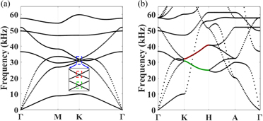
Figure 2. (a) Dispersion curves of the 3D lattice based on the unit cell shown in figure 1. (a) The dispersion along the 2D BZ in the kx–ky plane at kz = 0. The region marked in blue is magnified in the inset to show the presence of two Dirac points (marked by the red and green boxes). These degeneracies are protected by the symmetry of the triangular lattice in the x–y plane. (b) Dispersion curves plotted along the 2D BZ in the kx–kz plane at ky = 0. The nodal degeneracies at the corner of the BZ (marked in (a)) exist for all values of kz, thereby resulting in line degeneracies along the K–H directions indicated by the red and green lines.
Download figure:
Standard image High-resolution imageThe resulting degenerate nodes are Dirac points which are protected by the lattice symmetry of the hexagonal (graphene-like) arrangement of vertical cylinders. As previously mentioned, this degeneracy exists at all kz, hence resulting in the line degeneracies marked in red and green colors in figure 2(b). This behavior is a direct consequence of both P and T-symmetries being preserved. Breaking P-symmetry would result in lifting the line degeneracy along the kz direction hence resulting in the formation of a Weyl points.
2.2. P-symmetry breaking and Weyl points
In order to break P-symmetry, a chiral coupling can be introduced by means of straight slanted cylinders connecting top and bottom layers in proximity of the vertices of the hexagonal layer. The resulting unit cell is shown in figure 3 while its 3D BZ remains the same as the one shown in figure 1(c). The slanted cylinders are made of aluminum (as the plates) and have a radius of r2 = 2 mm. The dispersion curves along the boundary of 2D BZ in the kx–ky plane at kz = 0 and in the kx–kz plane at ky = 0 are calculated again and shown in figure 4. The degenerate points resulting from the linear intersection of two modes in figure 2(a) are also present in figure 4(a) (marked by the same red and green boxes). However, the line degeneracies previously observed in figure 2(b) are now lifted, due to P-breaking, and reduced to nodal degeneracies at the high-symmetry points K and H (see red and green circles figure 4(b)). These degeneracies are the Weyl points that are formed by the linear intersection of the two (initially degenerate) modes along all three directions. Figure 4(a) shows the linear intersection in the kx–ky plane while figure 4(b) shows the linear intersection in kx–kz plane.
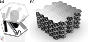
Figure 3. (a) Schematics of the unit cell with slanted cylinders. The cylinders have radius r2 and are made of aluminum. The resulting unit cell does not preserve P-symmetry and mirror symmetry. Periodic boundary conditions are used on the boundaries to create a 3D lattice. (b) Rendered view of a bulk piece of the 3D lattice.
Download figure:
Standard image High-resolution image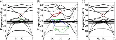
Figure 4. Dispersion curves for the 3D lattice with broken P-symmetry. (a) Dispersion along the 2D BZ in the kx–ky plane at kz = 0. The nodal degeneracies from figure 2(a) are still present, despite a slight shift in frequency. (b) Dispersion curves of the same 3D lattice along the 2D BZ in kx–kz plane at ky = 0. The line degeneracies in figure 2(b) are lifted (magnified image of the green modes is shown in the inset). The resulting nodal degeneracies at K and H are Weyl points, marked by red and green circles. (c) Dispersion curves along the 2D BZ in the kx–ky plane when  . The degeneracy indicated by the red box in figure 4(a) is now lifted, due to the nonzero value of kz, hence leaving behind a topological bandgap. The degeneracy marked by the green box in figure 4(a) is also lifted due to the nonzero value of kz, which opens a second (although narrower) bandgap.
Download figure:
Standard image High-resolution imageAs a result, the degeneracy marked in figure 4(a) is lifted for nonzero values of kz (with kz ≠ nπ/az for integer n) hence giving rise to a topological bandgap as shown in figure 4(c). The band structure shown in figure 4(c) corresponds to  , where az = h1 + 2h0 = 24 mm is the total height of unit cell. The subscripts ± of the high symmetry points' labels indicate
  , as also depicted in figure 1(c). The bandgap size varies with kz as shown in figure 4(b). Thus, kz can be treated as a parameter that controls either the opening or closing of the topologically nontrivial bandgap, provided that the system remains periodic along the z-direction.
3. Ab initio calculations of the topological properties
3.1. Topological charge
In order to assess the topological significance of the degeneracies identified in the chiral 3D lattice and, consequently, the existence of Weyl points, this section presents a numerical investigation into the calculation of the topological charge. The charge can be calculated by integrating the Berry curvature flux on a 2D manifold S enclosing the Weyl point in the reciprocal space, that is

where C is the topological monopole charge, i.e., the Chern number, dS is the vector surface element aligned with its local normal direction, and Ω is the Berry curvature (vector field) given by

where k is the wavevector, and  is the displacement eigenstate as a function of k. Consider the Weyl point at K, at a frequency of approximately 40 kHz, as indicated by the red dashed box in figure 4(a). This point corresponds to the intersection of the 16th and the 17th bands. To calculate the corresponding topological charge, we can integrate the Berry curvature flux threading the outer surface area (on the top, bottom, and side faces) of a fictitious prismatic manifold enclosing the K point (see figure 5). We anticipate, and show later, that the flux on the side faces is zero if a certain triangular prism is chosen as prototypical 2D manifold.
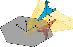
Figure 5. The topological charge at the K point can be calculated by integrating the outward Berry curvature flux of a 2D manifold enclosing the K point. In this case, the surfaces of a triangular prism are chosen.
Download figure:
Standard image High-resolution imageWithout loss of generality, we can select  as the top and bottom faces of the prism. At these planes, we have K+ and K− with the same (kx, ky) coordinate as the K point. The z-component of the Berry curvature on the top plane is then calculated using equation (2) (see figures 6(a) and (b)) for the 16th and 17th bands, respectively. Note that, at the two distinct points (i.e. they cannot be transformed into one another by translation symmetry operations), K+ and K'+ points exhibit the same Berry curvature pattern. This is a direct result of the C6 symmetry of the lattice. Therefore, if the 2D manifold is chosen to be the triangular prism with the right red dashed triangle in figure 6(a) as its top face, we can assure that the flux integral on the side faces of the prism is zero due to symmetry in the reciprocal space. In fact, the C6 symmetry guarantees that the outward flux on the side face ① equals the inward flux on the side face ② the same cyclic symmetry along with the translation symmetry (from the left to the right, for example) forces the flux integral on the entire side surface ③ to vanish.
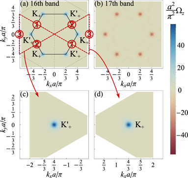
Figure 6. (a) and (b) The z-Berry curvature distribution of the 16th and 17th bands, respectively, on the kz = 0.1π/az plane. The two red dashed triangles in (a) indicate the top faces of the chosen prismatic manifolds enclosing the Weyl points, K or K' points, respectively. The total integral of the Berry curvature flux on the vertical side walls ①, ② and ③ of the prism vanishes due to the C6 and translation symmetry. (c) and (d) Zoomed-in view of the Berry curvature corresponding to the two triangular areas in (a). Each yields the outward flux integral of π, which shows the Weyl points K and K' are of +1 Chern number.
Download figure:
Standard image High-resolution imageIt follows that we only need to integrate the Berry curvature flux on the top and bottom faces. The bottom face which is around the K− point, is actually the time reversed counter-part of the triangular face around the K'+ point (inversion of (kx, ky, kz)) as shown in the left red dashed triangle in figure 6(a). T-symmetry requires that  which results in the z-component of the Berry curvature on the bottom face to have the same strength but opposite sign. Also, given that the dS element on the bottom face is oriented in the −kz direction, it still contributes a positive outward flux. As a result, the topological charge is the sum of the integrals of the Berry curvature calculated over the two red dashed triangles in figure 6(a).
The Bloch eigenmodes were solved numerically using the FE model. For this calculation, the momentum space around the K+ point was spanned by using a mesh of grid points (having (kx, ky) coordinates and placed on the top surfaces of the triangular prism) distributed according to an adaptive resolution scheme (that is, getting finer near the K+ point). The eigenmodes returned by the FE analysis contained some uncontrollable phase ambiguities. This is not an issue as long as such phase ambiguities are smooth enough across different grid points, so that the derivative operators in equation (2) can be calculated. To ensure such smoothness, we pre-processed the eigenmodes obtained from the FE analysis with a U(1) gauge transformation  throughout the surface;
  is a reference phase of the z-component of the displacement associated with a reference point in the unit cell (in our simulations this point was chosen as one of the unit cell vertices). It follows that the resulting eigenmodes all have this reference point as phase datum; this approach provides sufficient smoothness on the selected surfaces. The z-component of the Berry curvature is then calculated based on equation (2), and the partial derivatives are obtained via central differences as,


The Berry curvature integral on the selected surface P is also replaced by the discrete summation throughout the l grid points,

The results are shown in figures 6(c) and (d). The numerical integrals yield 3.1561 and 3.1479, respectively, hence confirming the monopole charge of +1 (with only +0.3% error). Using a very similar numerical approach, the topological charge at the H point can be found to be −1. This result is in agreement with the T-symmetric nature of the Weyl points which requires the appearance of the degeneracies in pairs of points with opposite charge. Figure 7 shows all the Weyl points within the half BZ (in the kz direction) and their corresponding topological monopole nature (either sink or source). On the kz = 0 plane, there are two Weyl points (K and K') both with charge +1 (that is sources of Berry curvature), while on the kz = π/az plane, each of the two Weyl points (H and H') are of charge −1 (that is sinks of Berry curvature).

Figure 7. Schematic illustration of the Weyl points within the kz > 0 half BZ and their corresponding topological monopole nature (either as a sink or a source).
Download figure:
Standard image High-resolution image3.2. Bandgap-Chern number
An alternative way to obtain the topological charge of the Weyl point is to use a topological invariant called the bandgap-Chern number Cg. This invariant is obtained by summing the Chern numbers of all the bands below the gap of interest. In the following, we consider kz as a parameter and focus on the bandgap that forms in the kx–ky plane. Cg remains constant with varying kz except at K and H where the bandgap closes and reopens and Cg experiences a sudden change in its value. This change is equal to the topological charge of the Weyl points on that plane because Weyl points act as either sources or sinks of Berry curvature flux [52]. This principle can be used to calculate the charge of the Weyl points in the band structure. Particularly, we focus on the degeneracies occurring at approximately 40 kHz. It is found that the Berry curvature integrals of the first 15 bands cancel each others, therefore Cg reduces to the integral of Berry curvature in the 2D BZ for the 16th mode only.
Figure 8 shows the plot of Cg as a function of kz for the Weyl points at 40 kHz. It clearly shows that Cg has a value of −1 for kz < 0 and +1 for kz > 0 which results in a net difference ΔCg = +2. This is consistent with the previous analysis that showed the kz = 0 plane to host two Weyl points of equal charge at K and K' due to intact T-symmetry. The two Weyl points at K and K' therefore have a topological charge of +1 each. In the same figure, there is also a change in the value of Cg at  . This indicates that the charge of the Weyl point at H (H') is −1. Once again, this is expected and consistent with the fact that Weyl points always occur in pairs with opposite topological charge. The nonzero value of charge also confirms that the nodal degenerate points under consideration are in fact Weyl points with nontrivial topological significance. In light of the bulk-surface correspondence [2], a nonzero Cg indicates that topological surface modes can exist within the target bandgap while the magnitude of Cg indicates how many surface modes should be expected. In our specific example, Cg = ±1 for kz ∈ (0, π/a) or kz ∈ (−π/a, 0), respectively. Compared with trivial materials (such as vacuum), there is a kz-locked net difference of ±1 in Cg. Therefore, one surface mode should be expected either in case of positive or negative kz. The corresponding surface states propagate unidirectionally either in the clockwise or counter-clockwise direction along the structure border (depending on the sign of Cg), as shown later on in the numerical simulations. This result further confirms that the selected geometry leads to the formation of Weyl points and it is capable of supporting topological surface states.
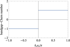
Figure 8. The bandgap-Chern number Cg associated with the gap around 40 kHz as a function of kz. As the bandgap closes and reopens at kz = 0, Cg experiences a +2 discontinuous jump in its value, which indicates the sum of topological monopole charges on the kz = 0 plane.
Download figure:
Standard image High-resolution imageWe note that the nonzero Chern number and the Berry curvature distribution for, as an example, kz = 0.1π/az (figure 6) is reminiscent of 2D topological materials manifesting quantum Hall effect (QHE) [61]. In QHE materials, T-symmetry is broken due to the use of an external field. In the present material, the chiral structure breaks the z-mirror symmetry therefore a mode propagating in the z-direction in the infinite lattice is expected to exhibit kz-locked unidirectional surface states. In fact, at steady state, the role of temporal and the spatial (in this case z) variables can be interchanged. A similar idea was also presented in studies of 3D Floquet topological insulators [62]. This latter aspect will be further clarified in the next section.
4. Supercell dispersion and surface modes
Weyl points with opposite topological charges are connected by nontrivial topological surface states that exist only on the boundary of the medium. In this section, we consider the physical response of a periodic supercell made out of the 3D unit cell described above. Consider a supercell having a finite dimension of 38 units in the y direction and infinite dimensions (obtained by means of periodic boundary conditions) in the x and z directions. Figure 9(a) shows the actual domain used for the numerical calculations.

Figure 9. (a) Supercell domain having finite size in the y-direction (38 units) and infinite size (via the application of periodic boundary conditions) in the x- and z-directions. (b) Dispersion curves corresponding to the supercell at  and in the neighborhood of the bandgap marked by red box in figure 4(c). Topological surface modes exist in the bandgap and are indicated in red and green color. The bulk modes are indicated in grey color. The green colored modes occur at the lower edge of the supercell while the red colored modes occur at the upper edge as indicated in figures 9(c) and (d), respectively. The eigenvectors corresponding to the points indicated by (c) the green star, and (d) the red star in the dispersion curves and plotted on the supercell.
Download figure:
Standard image High-resolution imageWe focus the following analysis on the topological bandgap that develops at the approximate frequency of 40 kHz and that is marked by the red box in figure 4(c). Figure 9(b) shows the dispersion curves for the supercell at  . It is evident from the visual inspection of the dispersion that the supercell admits two additional modes, the surface modes, that exist within the topological bandgap. Bulk modes are in grey color while the surface modes are indicated in green and red. The green modes correspond to the lower edge of the supercell while red modes correspond to upper edge. This correspondence is also reflected in the plot of the eigenvectors on the supercell shown in figures 9(c) and (d). The dispersion of the surface modes corresponding to the upper edge has a positive slope (i.e. positive group velocity), which means that these modes are expected to travel in the positive x-direction. Similarly, the surface modes defined on the lower edge have negative slope and therefore are expected to travel in the negative x-direction.
Further, it can be observed that the supercell in figure 9 is obtained by terminating the triangular lattice along the zigzag edge. However, triangular lattices exhibit also another edge type named the armchair edge. We explored the possible propagation and existence of topological modes also on this edge type. For this purpose, a finite size supercell terminated along the x-direction was developed, as shown in figure 10(a). The supercell extended indefinitely in the y and z directions (periodic boundary conditions were used to simulate the infinite size). The corresponding band structure at  is shown in figure 10(b). The bulk modes are marked in grey color, the surface modes corresponding to the right edge of the supercell are indicated in green color, and those corresponding to the left edge are indicated in red color. The eigenvectors corresponding to the surface states on both the right and left edges are shown in figures 10(c) and (d), respectively. Similar to the zigzag edge, the dispersion of the surface modes corresponding to the left edge has a positive slope (i.e. positive group velocity), which means that these modes are expected to travel in the positive y-direction. The surface modes defined on the right edge have negative slope and therefore are expected to travel in the negative y-direction. Therefore, if we assemble an extended 2D domain in the plane x–y we would expect to see the surface mode to propagate in a clockwise direction along the boundary of the lattice.

Figure 10. (a) Supercell domain having finite size in the x-direction (40 units) and infinite size (via the application of periodic boundary conditions) in the y- and z-directions. (b) Dispersion curves corresponding to the supercell at  around the bandgap marked by red box in figure 4(c). Topological surface modes exist in the bandgap and are indicated in red and green color, while the bulk modes are indicated in grey color. The green colored modes occur at the right edge of supercell while red colored modes occur at the left edge of the supercell as indicated in figures 10(c) and (d) respectively. The eigenvectors corresponding to the points indicated by (c) the green star (d) the red star in the dispersion curves and plotted on the supercell.
Download figure:
Standard image High-resolution imageFor  , the dispersion curves remain unaltered but the direction of propagation of the surface modes is reversed. The surface mode corresponding to the upper edge acquires a negative group velocity (propagation in the negative x-direction) while the surface mode corresponding to the lower edge acquires a positive group velocity (propagation in the positive x-direction). Similarly, the surface mode corresponding to the left edge acquires a negative group velocity (propagation in the negative y-direction) while the surface mode corresponding to the right edge acquires a positive group velocity (propagation in the positive y-direction). An extended 2D domain in the x–y plane would then show a wave propagating in the anti-clockwise sense along the boundaries.
The combined behavior illustrated above is well consistent with those of dynamical systems characterized by Weyl points and corresponding topologically nontrivial modes. Results also suggest that, upon injecting a wave into the system, the direction of propagation can be controlled by properly choosing the sign of kz. This latter aspect will be further clarified by means of full field simulations in the next section.
Another interesting feature of the proposed geometry is that the group velocity of the surface modes can be controlled simply by changing the radius of the center vertical cylinder r1. Figure 11 shows the dispersion curve of the supercell (a) for various values of r1. The group velocity of the surface modes decreases with increasing radius r1 of the center cylinder. This reduction of the group velocity can be explained by observing that by increasing r1 the homogenized mass density of the lattice increases, but without significantly increasing the rigidity. Hence, given that the eigenmode does not involve significant compressive or bending motion of the center cylinder, the surface modes tend to slow down. By tuning the radius r1, the surface states can gradually evolve from the single valley mechanism (similar to the 2D model discussed by Raghu [61]) to the intervalley mechanisms (similar to the model discussed in Kane [63]). In either case, the unidirectional gapless surface states connecting the lower and upper bulk bands are protected by the topological nature of the band structure and are guaranteed to be present. Note that, while a similar variation in the group velocity of the topological edge modes was earlier observed in 2D chiral materials [62], this tuning ability of the surface states in 3D lattice was never observed and documented in earlier studies.

Figure 11. Dispersion curves of the supercell shown in figure 9(a) for different values of the radius of the center cylinder. Values of r1 equal to (a) 4 mm (b) 5 mm (c) 6 mm (d) 7 mm (e) 8 mm (f) 9 mm are considered. It is seen that the group velocity of the topological surface modes decreases with increasing r1 and that the surface states evolve from a single-valley to an inter-valley dominated behavior.
Download figure:
Standard image High-resolution image5. Full field numerical simulations
Based on the 3D unit cell developed above, a complete domain in the x–y plane was also simulated in order to observe both the direction of propagation and the scattering behavior in presence of defects. The domain used is shown in figure 12(a). The domain is rectangular and finite along both the x- and y-directions. All edges except the bottom one were set to free boundaries. The boundaries normal to the z-axis were assigned periodic boundary conditions so to render the lattice infinite in this direction. Perfectly matched layers (PML) were used at the bottom edge to absorb the incoming wave and allow a clear assessment of the direction of propagation of the surface state when performing a steady state analysis (i.e. it avoids the surface mode to propagate all around the boundary and get back to the source).
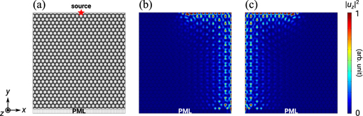
Figure 12. Full field simulations demonstrating unidirectional propagation of the surface state. (a) Domain used for full field simulations. The domain is finite in size along the x- and y-directions but it employs periodic boundary conditions along the z-direction. A PML boundary was applied along the bottom edge of the domain to absorb the incoming wave in steady-state analyses. The wave was injected by means of a harmonic point force applied at the location marked by the red star at a frequency of 40 kHz. (b) Steady-state response showing the propagation of the surface state when excited with  . 99.41% of power is injected into the right branch. (c) Steady-state response showing the propagation of the surface state when excited with
  . These results clearly show the unidirectional nature of the topological surface modes. 99.93% of power is injected into the left branch.
Download figure:
Standard image High-resolution imageThe domain was excited by a harmonic point force acting in the z-direction at the location indicated by the red star marker in figure 12(a). A harmonic excitation at a frequency of 40 kHz was selected because it lies right within the target topological bandgap where surface states exist. At  , the source excites the surface state with positive group velocity which is observed propagating in the clockwise direction (see figure 12(b)). At
  , the situation is inverted and the source excites a counter-clockwise propagating surface state (figure 12(c)). These results confirm previous observations concerning the one-way propagation property of the surface states. These results also allow an additional observation on the back scattering immune properties of the surface states. As the wave propagates beyond the corner of the rectangular domain, the wave amplitude on both sides is exactly comparable. This suggests that there are no significant reflections taking place at the sharp corner and the wave is capable of propagating unidirectionally. To quantitatively evaluate the unidirectional propagating performance, we evaluate and compare the emitted power at the PML by integrating the outward mechanical energy flux through the three most outer cells. 99.41% of the input power is transmitted to the right end in the case shown in figure 12(b) and 99.93% of the input power to the left end in the case shown in figure 12(c). The very small deviation from the expected 100% is due to the fact that the frequency at which the source is actuated, although in the region of the bulk bandgap, still generates evanescent bulk waves which travel almost isotropically. The evanescent bulk waves propagate all the way to the two ends of the computational domain where we evaluate the mechanical energy flux. We find that they contribute approximately in equal parts at both terminals; this results in seemingly lower performance in terms of uni-directional propagation. Also, the surface states themselves have evanescent field penetrating into the bulk with a certain decay length. Given the finite size of the model and the proximity to PMLs, some energy might get absorbed before reaching the measurement location. Despite these minor computational aspects, results clearly demonstrate uni-directional propagation and an almost complete lack of back scattering.
It should be noted that while the states propagate with the same intensity along the x- and y-aligned edges, they are associated with different eigenstates. This can be clearly observed in figures 12(b) and (c), and it is due to the different structure of the edges (i.e. zigzag versus armchair).
In order to put this results in perspective, we also show the performance in approximately equivalent non-topological waveguide modes. Figures 13(a) and (e) show the geometry and the response of an elastic half-space (simulated by a finite domain with PML) subject to a harmonic source located at the top surface. As expected, non-leaky Rayleigh surface wave propagates along the surface. Figures 13(b) and (f) show the geometry and the response of a similar waveguide when a sharp corner is inserted on its path. The interference pattern evident in the response along the top edge and the very attenuated propagation along the vertical edge provide concrete evidence of the strong back-scattering occurring at the corner. Also, some degree of scattering into the bulk is clearly visible. It is also well-known that waveguides can be built based on the concept of a phononic bandgap. In figures 13(c) and (g), we adopt the 2D phononic waveguide proposed by Sun and Wu [64] which was based on an array of steel rods embedded in a uniform epoxy matrix. The phononic waveguide is assumed infinite in the z-direction, therefore resembling a surface-like waveguide. We also assume kz = 0.1π/a, similar to the above conditions used in the simulations of the topological surface state. Figures 13(d) and (h) show the geometry and the response of the waveguide in presence of a sharp corner. Albeit no leakage is visible into the bulk, the reflection taking place at the corner is still severe, as visible by a standing-wave-like pattern in the horizontal branch and by the sharp decrease in wave amplitude in the vertical branch. Studies have explored the use of additional scatterers placed near the corner [65] in order to improve the transmission, however a transmission coefficient of 72% (52% power) was achieved; still very limited compared to topological designs.

Figure 13. Non-topological waveguides provided for comparison. (a) and (e) The numerical model geometry and the response of an elastic half-space waveguide (simulated by a finite domain with PML) subject to a harmonic source applied at its top surface. Non-leaky Rayleigh surface wave propagates along the surface. (b) and (f) The geometry and the response of a similar surface waveguide when a sharp corner is inserted on its path. The interference pattern evident in the response along the top edge and the very attenuated propagation along the vertical edge provide concrete evidence of the strong back-scattering occurring at the corner. Also, some degree of scattering into the bulk is clearly visible (c) and (g) the geometry and the response of 2D phononic waveguide composed of steel rod array embedded in the epoxy matrix. The phononic waveguide is assumed infinite in the z-direction therefore resembling a surface-like waveguide. kz = 0.1π/a is assumed. (d) and (h) The geometry and the response of the phononic waveguide in presence of a sharp corner. Albeit no visible leakage into the bulk, the reflection taking place at the corner is still severe.
Download figure:
Standard image High-resolution imageThe immunity to back-scattering was also assessed by performing full field simulations on domains with three different types of either disorder or defect. Figures 14(a) and (e) show the geometry and the steady-state response of the reference configuration having neither edge defects nor disorder. The power transmission coefficient evaluated at the bottom-right end is 98.87%. Figures 14 (b) and (f) show the geometry and the steady-state response of a domain having randomly shifted center pillars in each of the 24 unit cells near the top free boundary. The inset in (b) shows the magnified image of the shifted pillars. Each of them is shifted away from its original position of a random distance between ±0.15a in both the x- and y-directions. The power transmission coefficient evaluated at the bottom-right end is 98.85%. Figures 14 (c) and (g) show the geometry and the steady-state response of a domain with center pillars removed in the 24 unit cells near the top free boundary. The inset in (c) shows the magnified image of the missing pillars. The power transmission coefficient evaluated at the bottom-right end is 99.53%. Finally, figures 14 (d) and (h) show the geometry and the steady-state response of a domain with a rectangular cut on the top edge. The power transmission coefficient evaluated at the bottom-right end is 97.64%. It is found that less than 1.23% (i.e. −0.05 dB) of power transmission loss occurred in the three cases; part of this loss also due to computational aspects as previously discussed. However, by direct comparison with the reference configuration, these are found to be minor differences in the transmission coefficients, hence confirming the robustness of the edge states against various types of in-plane disorder and defect.

Figure 14. Full field numerical simulations on domains with three different types of disorder or defect. (a) and (e) The geometry and the steady-state response of the reference configuration without either edge defect or disorder. The evaluated power transmission coefficient at the bottom-right end is 98.87%. (b) and (f) The geometry and the steady-state response of a domain having randomly shifted center pillars in each of the 24 unit cells near the free boundary. The inset in (b) shows the magnified image of the shifted pillars. Each of them is shifted away from its original position of a random distance between ±0.15a in both the x- and y-directions. The evaluated power transmission coefficient at the bottom-right end is 98.85%. (c) and (g) The geometry and the steady-state response of a domain with center pillars removed in the 24 unit cells near the free boundary. The inset in (c) shows the magnified image of the missing pillars. The evaluated power transmission coefficient at the bottom-right end is 99.53%. (d) and (h) The geometry and the steady-state response of a domain with a rectangular cut. The evaluated power transmission coefficient at the bottom-right end is 97.64%. Minor differences in the transmission coefficients compared to the reference configuration indicates that the edge state is robust against various types of disorder and defect.
Download figure:
Standard image High-resolution image
We note that the origin of the robustness can be connected to the kz-locking of the uni-directional surface states. In other words, with positive (negative) kz fixed, there is only one uni-directional clockwise (counterclockwise) surface state that can propagate along the boundary. Therefore, the surface state is backscattering immune in the presence of all kz-preserving perturbations, including those characterized by strong disorder/defect on the xy-plane, as far as they preserve the periodicity along the z-axis. In presence of disturbances destroying the kz protection, such as strong short-range perturbation along the z-axis (e.g. missing center pillars in one layer along the z-axis), the z-momentum will be altered and the kz could potentially change sign, therefore resulting in backscattering.
6. Conclusions
Weyl points and topological surface modes in elastic solid media are still in their early stages of formulation and design. The very few implementations proposed to-date are based on discrete designs that are not conducive to use in practical applications, particularly those requiring load-bearing designs. Examples might include stress wave management for vibration control or energy harvesting in structural systems subject to distributed loads (such as those associated with by aero- or fluid-dynamic forces). This study presented a fully continuous, load-bearing, elastic material capable of unidirectionally-propagating and topologically-protected surface states. The design of the 3D unit cell, inspired to sandwich composites, consisted in a layered prismatic lattice with hexagonal cross section in which the layers were spaced by solid cylindrical elements and by slanted circular beams connecting consecutive faces of the prismatic unit cell. The cylinders were used to set the necessary in-plane symmetry conditions and to provide high load carrying capacity. The slanted beams were used to achieve chirality and allowed achieving the necessary P-symmetry breaking condition.
The analysis of the lattice dynamics highlighted the existence of Weyl points following the breaking of the z-mirror-symmetry and the P-symmetry of the lattice. To gain insight into the mechanism leading to the formation of these degenerate points, we evaluated the topological invariants using ab initio calculations and without employing any further simplifications. Results were very well aligned with the expected integer values. The relationship between the surface states and the topological invariants was also explored from different perspectives. kz-locked unidirectional propagating surface elastic states were predicted on the external surface of the 3D lattice and their existence was further confirmed by full field numerical simulations. Numerical results also confirmed the extreme robustness of these states against strong lattice defects. This study may serve as a basis to develop composite-like structures having advanced elastic waveguiding capabilities for applications in fields such as vibration control, energy harvesting, structural health monitoring, and on-chip telecommunication signal processing.
Acknowledgments
The authors gratefully acknowledge the partial financial support of the National Science Foundation under Grant No. 1761423, and of the Office of Naval Research.