Improved Road Segment-Based Geographical Routing Protocol for Vehicular Ad-hoc Networks
by
 , , and
Kashif Naseer Qureshi
1 ,
,
Farooq Ul Islam
1, 
Omprakash Kaiwartya
2,* ,
,
Arvind Kumar
3 and
Jaime Lloret
4,5 1
Department of Computer Science, Bahria University, Islamabad 44000, Pakistan
2
School of Science and Technology, Nottingham Trent University, Nottingham NG11 8NS, UK
3
Department of Computer Science and Engineering, Galgotias University, Uttar Pradesh 203201, India
4
Department of Communications, Universitat Politècnica de València, 46022 Valencia, Spain
5
School of Computing and Digital Technologies, Staffordshire University, Stoke ST4 2DE, UK
*
Author to whom correspondence should be addressed.
Electronics 2020, 9(8), 1248; https://doi.org/10.3390/electronics9081248
Submission received: 2 May 2020
/
Revised: 25 July 2020
/
Accepted: 30 July 2020
/
Published: 4 August 2020
(This article belongs to the Special Issue Vehicular Networks and Communications)
Abstract
:The real-time traffic information dissemination among on-road vehicles has been envisioned via realizing vehicular ad hoc networks (VANETs) as smart service-oriented roadside wireless sensor networks. The network enables various types of real-time traffic applications related to safety and infotainment for drivers and passengers. The information dissemination-centric routing protocols for vehicular networks have to dynamically adopt under the constrained network environment while considering the higher mobility of vehicular nodes and unpredictable physical topologies in the network. The issue needs to be addressed through smart and network-aware routing protocols. Geographical routing protocols have witnessed significant attention for information dissemination under these types of dynamic vehicular network environment. To this end, this paper presents an improved road segment-based geographical routing (ISR) protocol focusing on better head node selection for information dissemination. It divides the forwarding area into a number of road segments and selects a head node on each segment by focusing on traffic-aware information including the location, direction, and link quality-centric score for every vehicle on each road segment. Algorithms were developed for the complete process of head node selection and information dissemination among vehicles on the road segments. The simulation results attested the performance benefits of the proposed routing framework as compared to the state-of-the-art protocols considering dynamic vehicular traffic environment-related metrics.
1. Introduction
Real-time data communication among on-road vehicle nodes can be enabled by realizing vehicular ad hoc networks (VANETs) with or without the support of existing infrastructure alongside roads [1]. This networking field has gained significant popularity among researchers and automobile industries because of its different types of advanced traffic applications. Most of the applications in this area offer convenience and improvement in road safety. In addition, the safety applications contain information to alert drivers in case of accidents, traffic congestion, repair work, emergency braking, available parking spaces, and the presence of police radar and emergency response vehicles [2]. Vehicle nodes are taking advantage of new and advanced networking technologies, and they are reducing the deployment cost of on-road wireless communication devices. Indeed, by the installation of sensor node enabled communication kit in vehicles or at the edges of roads and in control centers, vehicular communications can alert drivers for possible dangers on the road ahead in advance. Additionally, to improve data communication and road safety, vehicular networks offer new services to road users for more convenience and road safety [3]. Several research projects related to road safety have been running in academia and industries, where different electronic devices are installed in vehicle nodes to develop such a network including radars, cameras, and global positioning system (GPS) tracking systems. Vehicular nodes contain an on-board unit (OBU) that is attached to the vehicle to enable communication with other OBUs and roadside units (RSUs). An RSU refers to a node or base station installed on the roadside that provides connectivity among vehicle nodes. It allows easy access to the network and provides further connection to the main network control station. Two types of vehicular communications are mainly realized in VANETs including vehicle-to-vehicle (V2V) and vehicle-to-infrastructure (V2I) [4].
The design of information dissemination-centric routing protocols is one of the most challenging tasks in realizing VANETs due to the dynamic vehicular network environment when considering the higher mobility of vehicular nodes and unpredictable vehicular network topologies [5]. Because of these constraints, the exchanged network information among nodes becomes outdated quite frequently. It results in network disconnections and packet dropping issues in information dissemination. These issues have been addressed in different vehicular network routing protocols that have considered limited network parameter predictions [6]. Vehicle node movement in VANETs is typically restricted in two-way roads and streets. The routing protocols that use physical location information of the nodes received from GPS and existing road or street map knowledge are the best to consider for routing decisions in the vehicular environment [7]. There are still various challenges for the deployment of VANETs and the development of related traffic applications such as the unstable movement of traffic that results in multi-path topologies and insufficient physical network deployment in terms of lack of RSUs [8]. Thus, the higher mobility of vehicle nodes and unpredictable network topologies transform VANETs into highly dynamic network environments.
For predicting network topology, several incremental packets increase the network overhead in a vehicular traffic environment. The frequent network disconnections mostly happen in a sparse network environment where the distance between vehicle nodes is longer than dense traffic areas [9]. Furthermore, obstacles, like the different sizes of vehicles and high rise buildings, are some other issues that lead to network disconnection. It is little easy to establish a communication path between vehicles to communicate in a dense traffic network environment. In contrast, in lower vehicle density environments, frequent network disconnections lead to network overhead and stale packets [10]. In such a scenario, the vehicle takes a longer time for data delivery or, sometimes, the packets are dropped in-between communications in the networks. In geographical routing-centric information dissemination, nodes always find neighbor nodes that are closer to the destination and transmit the data packet towards the same. Many geographical routing protocols have been suggested based on greedy forwarding, where the source node selects the relay node near the destination within its communication range to forward the data [11,12]. The limitation of greedy geographical forwarding is that it does not always work, particularly in sparse vehicular network environments [13]. There might be a situation where a node may not find a closer node than itself to the destination to forward the data. Due to the dynamic nature of VANETs, packets can be sent in the wrong direction due to the existence of a routing loop in the network. This loop is induced by a right-hand rule that is used to overcome the problem of void network scenarios [14]. To address these issues, a robust geographical routing protocol must be aware of more appropriate routing information to address network disconnection issues with lower network overheads for routing information gathering [15]. In this context, the main aim of this paper was to design and develop an improved road segment-based geographical routing protocol (ISR). The contributions in the paper can be summarized as follows:
- Firstly, the design of ISR is presented considering segment formation, head node selection, and score calculation.
- Secondly, algorithms were developed for the complete process execution of head node-based information dissemination in a vehicular traffic environment.
- Thirdly, simulations are performed to assess the performance benefits of the proposed information dissemination-centric vehicular routing framework.
The remainder of the paper is structured as follows. Section 2 discusses the literature review of existing geographical routing protocols. Section 3 presents the detail of the proposed ISR framework. Section 4 discusses the simulation setup and results. Section 5 presents the conclusion and future work.
2. Related Works
In the literature, different routing protocols have been suggested for information dissemination in VANETs. Due to the unique and challenging network characteristics of VANETs, including rapid changes in network topologies and the high mobility of nodes, most of the protocols in the literature are not so feasible for dealing with each type of network constraints. Therefore, various improvements of existing routing protocols have been taken into consideration for information dissemination [16]. There are five main categories of routing protocols: topology-based routing, geographical routing, cluster-based routing, broadcast routing, and geocast routing protocols. Topology-based routing protocols are based on a neighbor node receiving information and updating routing tables. It is further classified into reactive and proactive types of routing. Geographical routing refers to transferring the data packet by using the position information of vehicle nodes. Geographical routing needs additional resources like GPS to get the node’s position information of neighbors and its own for routing. Cluster-based routing protocols create a virtual arrangement of nodes known as on-road vehicle groups. Each group has one group leader that is responsible for data communication between different other groups. Intra-node data communication is done via local links.
A reactive routing protocol has been suggested as a Modified version of Location-Aided Routing scheme 1 (MLAR1) [17]. This protocol uses three packets to send data and maintain connections including route request, route reply, and route error packets. Route request packets are further classified into two types. They get information about the destination as modified route request packets. In addition, when a route breaks during communication, the original route-request packet is used for alternative route establishment. To reduce the size of the modified route request packet, this protocol removes the redundant fields, flooding the variable field and zone-centric non-variable field. Authors have claimed that due to this modified request strategy, the protocol has less overhead and better performance. However, this type of protocol strategy might have a lesser overhead but involves complex route request processes that result in network processing delays in vehicular traffic environment. An enhanced bandwidth efficient acknowledgment-based multicast (EBEAM) protocol has been suggested for VANETs [18]. This protocol is an enhanced version of variant of the BEAM protocol that was not performing well for emergency application messages, as the protocol was experiencing multicar chain collision issues. The enhanced protocol has overcome the BEAM limitations. In this enhanced protocol, all messages could be shared between the cluster head (CH) and the RSU to deliver information among all vehicle nodes. In the previous protocol, only a multicasting group member vehicle node got emergency messages. However, in the enhanced protocol, all vehicle nodes can get messages whether that are group members or not. However, the protocol has extra overhead due to its complex dissemination process where every node gets emergency messages.
A perception-based geographical routing protocol (PGRP) has been explored for VANETs [19]. To select the next hop, this protocol considers routing parameters including the central node and the distance and direction of the vehicle nodes. In this protocol, each vehicle continuously broadcasts a beacon message to get the information of other vehicles. It considers the central vehicle for forwarding data packets rather than selecting the outermost vehicle with a higher chance to exit from the transmission range. It uses a carry and forward approach to address the dis-connectivity problem. It has been claimed that the PGRP has better results than exiting routing protocols. However, it considers the central node as an assumption to test the routing protocol, which does not support real scenarios in VANETs’ traffic environments. An ant colony optimization-based ad hoc demand distance vector reliability (AODV-R) routing protocol has been investigated for VANETs [20]. This protocol uses optimal route selection and data aggregation as routing parameters. This protocol is the enhanced version of ad hoc demand distance vector (AODV) routing protocol. It considers the route having the shortest distance in terms of the hop count as used in Dijkstra algorithm, and clustering methods to reduce network overhead during information dissemination. Ant colony optimization is also used as another optimization method to find the shortest route with the minimum distance and route reliability. By a combination of ant colony and clustering, this protocol claims better performance than exiting routing protocols. However, the Dijkstra algorithm only works when all routing link weights are positive, and this assumption is not always valid in VANETs scenarios.
A prediction-based geographical routing (PGR) protocol has been suggested to improve the geographical routing strategy over VANET (GROOV) by using a network prediction method. It redesigned the forwarding and repairing mechanisms of GROOV protocol [21]. This protocol does not use pure routing and greedy forwarding approaches. Basically, this protocol enhances the prediction before an intersection and then saves the one hop information. It has been claimed in simulation results that the PGR performance is better in terms of hop counts, network latency, and the packet delivery ratio in both vehicular network environment including dense and sparse VANETs. However, vehicle networks are unpredictable in nature, making the network prediction method unsuitable to monitor network parameters for routing decision making. A Street-centric opportunistic Routing Protocol using Expected transmission cost (SRPE) has been investigated for vehicular traffic environments [22]. This protocol uses an expected transmission cost over a multi-hop forwarding path. In their work, the authors used winner procedure to measure the chances of link availability. An opportunist routing scheme is used for signal the fading mobility of the vehicle nodes, considering whether the vehicle state is stable or unstable according to the actions of the vehicle nodes. Routing decisions are taken at the intersection without topology information. Different combinations of the link are used to send packets to achieve a high throughput under limited-resource centric vehicular networks. However, this protocol dynamically forwards data packets by using adjacent street information. This strategy is not suitable under a vehicular network scenario with intermittent connectivity under sparse or dense vehicular networks. An analytical hierarchical process (AHP)-based multi-metric geographical routing protocol (AMGRP) has been investigated [23]. This protocol is the enhancement of the existing GPSR routing protocol. It adopts an AHP by considering multiple metrics including link lifetime, node density, and node status to find the best route in a network. However, when a protocol uses more routing metrics, it comes with more process complexities resulting in network delay and greater network overheads in VANETs scenario.
Traffic-aware segment-based routing (TASR) has been explored for VANET environments [24]. This protocol considers real-time traffic information for route selection. To calculate the strength of the segment, a metric called the estimated connectivity degree (ECD) is adopted. It considers traffic density and vehicle position as major routing parameters. Routing decisions are made depending on the information of segments. Each segment has two head nodes present on its corners. Each vehicle sends hello message containing nearby traffic density and vehicle’s position within the road segment which is used for making routing decision. However, the ECD cannot be recommended for higher mobility networks due to the complex and unpredictable network topologies of VANETs. Virtual backbone routing protocol (VBRP) has been suggested for VANETs [25]. In this protocol, the virtual backbone is distributed in each segment based on the stability index. It considers the link stability between vehicle nodes and their mobility patterns. This protocol utilizes RSUs to assist in routing decision making by overcoming the local maximum problem and improving the data transmission ratio in the network. In this protocol, the transmission is dependent on backbone nodes, and a normal node only receives data while all the transmission possible through the backbone node that receives and sends the data. However, this protocol adopts RSUs for routing decision making. This assumption limits this protocol to infrastructure-based scenarios where an RSU is always available. Table 1 shows the comparison of routing protocols by considering some standard metrics.
3. Improved Road Segment-Based Geographical Routing Protocol
The ISR protocol uses segments to perform the information dissemination-centric routing in the urban VANETs environment. The proposed routing protocol is based on routing parameters including vehicular node position information, direction, traffic density, and link quality between the communicating nodes in the network. ISR divides the road map into segments of road and initiates routing via the physical location information of the head nodes in each segment. The routing decision depends on the segment information with a look-ahead of the next segment information. The next segment that is selected has a high traffic density. The main aim of ISR is to improve the success rate of the routing protocol and its dynamic assessment regarding the multi hop forwarding abilities and road segment formation, along with the connectivity for the vehicular network. The design and development of the routing framework is detailed below. The notations used in the routing framework design and development are precisely described in Table 2.
3.1. Segment Formation
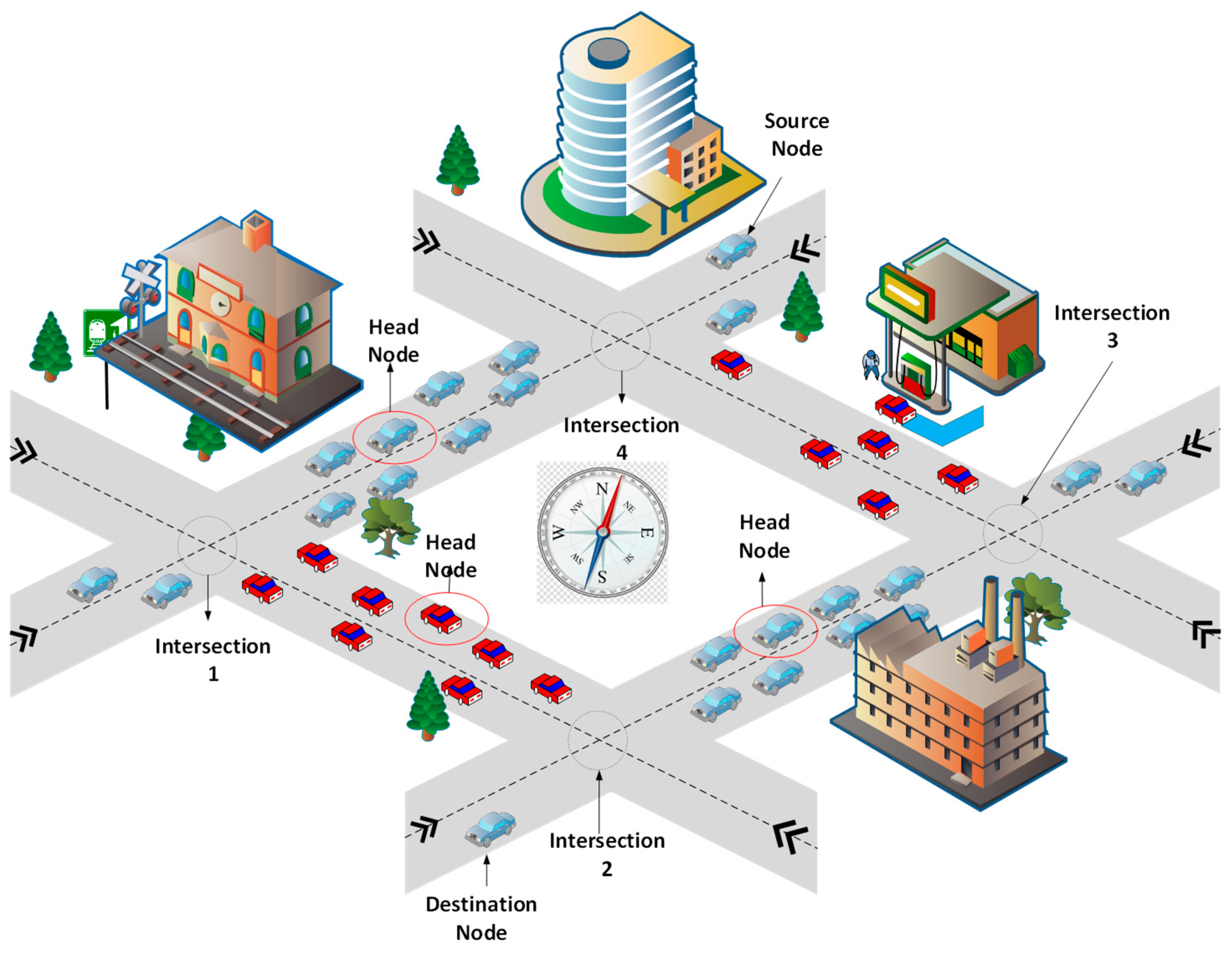
The proposed routing protocol is based on the routing parameters of the distance, direction, link quality, and traffic density of the networks. When the source node finds the destination out of its direct communication range, the protocol divides the forwarding path into small road segments with the help of the location information of vehicles and the road map information of the nearby area. Each vehicle is considered to be equipped with an OBU and a digital road map of the nearby area. It comprises street-level maps and precise traffic statistics. In Figure 1, a trajectory model of the ISR protocol is presented, focusing on intersection and segment formation. Here, segments are identified by considering the road trajectory and the number of intersections from source to destination in the vehicular network.
3.2. Head Node Selection
The head node (HN) is an appropriate forwarding vehicle node for information dissemination in a traffic environment. The HN selection process starts for every segment after the completion of segment formation operation on the nearby road map. Each vehicular node shares the information of its own position, direction, and link quality to its neighbor nodes within the segment. The protocol checks the position and direction of each neighboring vehicle for selecting the HN. The direction is calculated entirely in respect to the current location and available road trajectories in different possible directions. Then protocol check the position of node at time t and t+1, as expressed and in Equations (1)–(3) for the calculation of road direction-oriented distance. The segment-centric distance of node decreases towards the destination, as shows in Equation (4).
After this process, the position is calculated with the help of the Pythagoras theorem, as mentioned in Equation (4).
When there is a tie between two or more nodes in terms of distance and direction and the nodes are present in the central position, the protocol checks the link quality-based score of the nodes for further prioritizing the nodes as mentioned below.
3.3. Score Function for HN Prioritization
After the explanation of the routing parameter calculation, this section presents the score function calculation for HN prioritization. The first metric is position, where vehicle node is presented in central position. The progressive distance towards the destination is one of the significant routing metrics in the geographical routing protocol. The next routing metric is the direction towards the destination where the next forwarder node only selects the node that is moving towards the destination to avoid looping issues. The direction difference-oriented score for a vehicle can be expressed as given in Equation (5).
where is the decisive factor for direction, which is considered 0.5 in the network environment, and the direction of vehicle is represented as and . It is clarified that when the direction of both the vehicles is the same , the direction-based score is 1 in Equation (5). Similarly, when the direction of the vehicles is opposite to each other , the direction-based score is 0 in Equation (5). Furthermore, when the difference in the direction of the vehicles is , the direction-based score is between 0 and 0.5. Similarly, when the difference in direction of the vehicles is , direction-based score is between 0.5 and 1. This is effectively represented in Equation (5). Similar representation also follows in Equation (6) where the speed difference-based score is calculated using the function. The third metric is link quality when there is a tie in the direction-oriented score between two or more nodes, and then ISR checks the speed-based link quality of the nodes and chooses the better node between them, as shown in Equation (6), for calculating speed difference-oriented score .
where is the decisive factor for speed-based link quality, which is considered 0.5 in the network environment, and the speed of vehicle is represented as and . The overall score can be calculated as for each candidate HN during selection. The node with the higher score is finally selected as the HN for the considered road segment. Here, the weighting factor for selecting the HN must be less than or equal to 1. When there is only a single node presented in the central position, it is elected as the HN using Equation (5), and if there is tie between nodes, then Equation (6) is executed for selecting the HN with the final score.
3.4. Head Node Selection Process, Flowchart and Algorithm
An HN performs the following operations:
- The HN multicasts its unique ID to its segment members after election and to its neighboring HN.
- The HN collects the segment information (SI), which contains other vehicle information and disseminates it to the other available HNs in neighboring segments.
- The HN chooses the node-to-node segment transmitter that is based on the collected information, as explained above.
- After moving out of the segment, the protocol reinitiates the process for selecting a new HN.
For the HN selection, the proposed protocol multicasts the unique ID message to its neighbor nodes and also collects the SI that includes the other vehicle node’s information before forwarding it to other available HNs in neighboring road segments. Figure 2 shows the complete process of the steps of HN selection, where the ISR processes the routing metrics and selects the best candidate node as the HN.
Explanation of Algorithm 1: The HN selection starts with the segment formation. Once the number of segments is identified, the center point of segment and the nearest node to center point are identified in steps 3–5. In steps 6–12, for each candidate HN, in cases of more than one possibility, the distance of nodes is calculated between communicating nodes. Furthermore, in steps 13–17, the score of each node is calculated using Equations (5) and (6) by considering the direction- and speed-based weighting score of nodes. Moreover, the overall score is calculated by adding the direction-based score and the speed-centric link quality score for each node for the final HN selection.
Complexity of Algorithm 1: The complexity analysis of an algorithm majorly depends on the execution of the computing-centric steps. Here, the complexity of the algorithm depends on two criterion parameters: number of segments and the average number of vehicles in each segment . There are two computing-centric loops in the algorithm. The first loop is executed times in steps 1–18, and the second loop is executed times in steps 6–12. Considering the operation in steps 3–5 as unit or linear operations, the overall complexity of the algorithm can be expressed in the order of .
| Algorithm 1: Head Node selection. | ||||
| Input: Position of node | ||||
| Output: Head Node | ||||
| 1: | For | each segment | ||
| 2: | do | |||
| 3: | Compute Centerpoint for i | |||
| 4: | Length Centerpoint[i] = Centerpoint[i]; | |||
| 5: | J(i) = Nodes nearest to Centerpoint[i]; | |||
| 6: | For | each J(i) | ||
| 7: | Compute direction through Distance(c) | |||
| 8: | If | Distance(c) < Distance | ||
| 9: | Select node(i) as HN | |||
| 10: | End if | |||
| 11: | End for | |||
| 12: | If | nodes > 1 | ||
| 13: | Check link quality-centric score of nodes | |||
| 14: | Else | |||
| 15: | Call Weighting factor as mentioned Equation (6). | |||
| 16: | End for | |||
It is clarified that head node selection is performed on the same road segment, so Euclidean distance is considered in Equation (4). Furthermore, the selection is carried out by not only considering distance rather over the other parameters discussed in Section 3.2, Section 3.3 and Section 3.4.
3.5. Routing Process, Flowchart and Algorithms
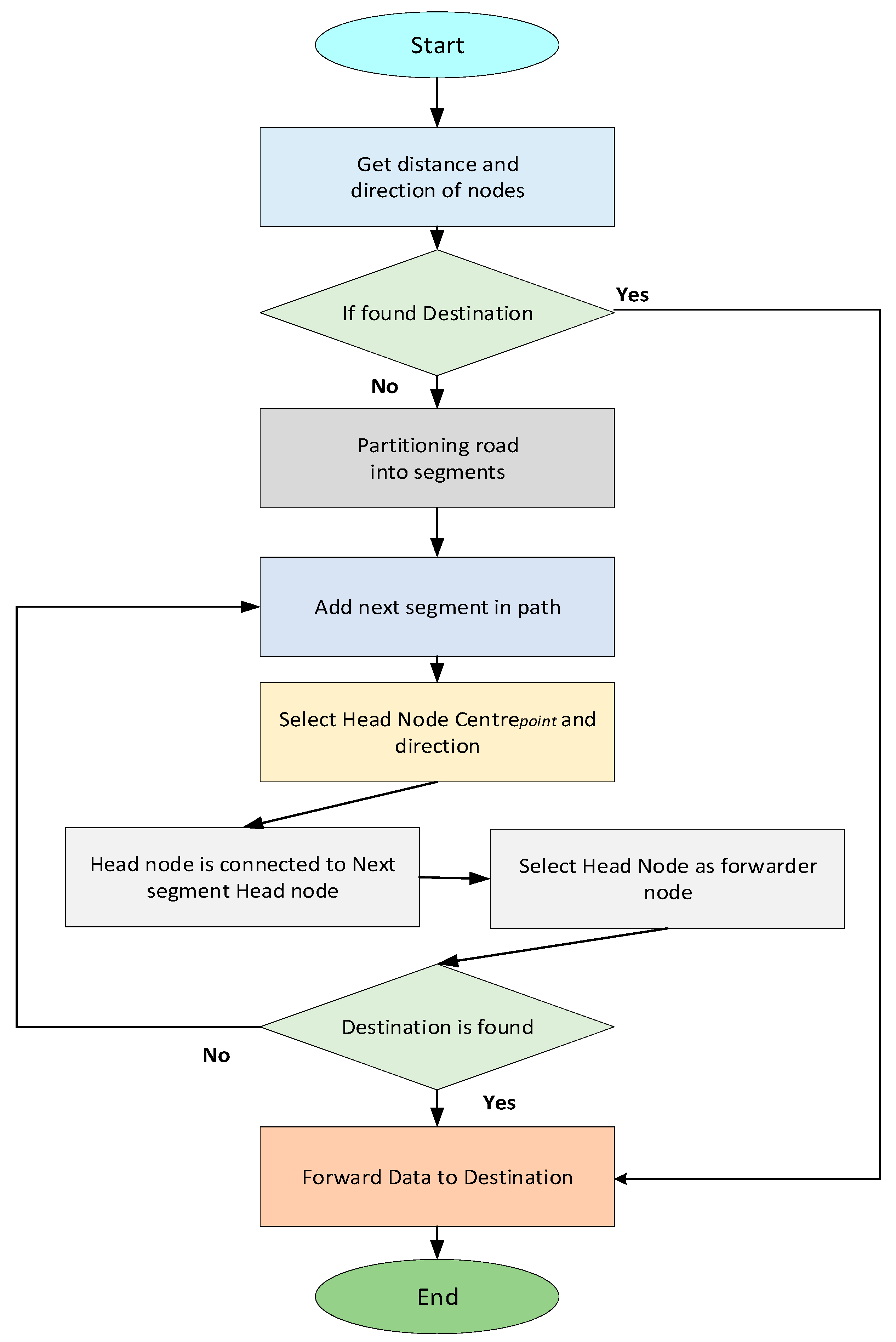
Figure 3 presents a flowchart of the proposed protocol routing process executed at road intersections and in-between road intersections.
3.5.1. Direct Communication
When the destination vehicle node and the source node are in same communication range or in the same segment, the source vehicle directly sends the data to the destination node. Algorithm 2 shows the process of the direct communication between same-segment vehicular nodes. The protocol gets the location of nodes through a GPS receiver attached to each vehicle. The notations used in algorithms are described in Table 2.
| Algorithm 2: Direct Communication. | ||
| Input: Position of nodes. | ||
| Output: Send packet | ||
| 1: | If | (ni == d) & ni ∈ [Ss ∨ Snext] |
| 2: | Send packet P → d | |
| 3: | else | |
| 4: | Algorithm 3 | |
3.5.2. Inter Segment Communication
To commensurate with the dynamicity of on-road vehicles, ISR intelligently selects appropriate segments. The vehicular node that is nearest to the central point and its direction towards the destination is considered the HN. The segment node information is distributed within and out of the segment to support routing decision making. After the selection process, the HN acts as a forwarder and only sends the data to its neighboring HN in communications involving more than one segment. The ISR protocol gives a solution to reduce the transmission overhead for each node to eliminate broadcasting in the whole network. The steps of the segment formation and HN selection process are presented in Algorithm 3.
| Algorithm 3: Segment Formation. | ||||
| Input: Ss ≠ Sd | ||||
| Output: Transmit data | ||||
| 1: | if | |||
| 2: | RD not seen before | |||
| 3: | If | (Ss ≠ Sd) | ||
| 4: | ||||
| 5: | Add HNi segment to path | |||
| 6: | Select Head Node (as Algorithm 1) | |||
| 7: | if | (HNi are connected to NSHi | ||
| 8: | ||||
| 9: | select HNi as forwarder | |||
| 10: | End if | |||
| 11: | Transmit packet P → ni s.t. ni= d ∨ ni∈Sd | |||
| 12: | End if | |||
| 13: | End if | |||
4. Results and Discussion
The simulation setup is a very important factor to analyze and validate research objectives. In this study, Network Simulator NS-2.34 was used with a mobility model generator for VANETs (MOVE). Simulation for urban mobility (SUMO) was considered for the urban traffic environment realization, as in [26]. VANETs were implemented in an on-road traffic scenario, with the consideration of the number of connecting intersections and vehicles with different turning probabilities in each intersection. The proposed ISR protocol was designed for urban situations including possible obstacles and dense traffic environments on roads. These environmental conditions were considered in the design of the proposed ISR. Some of the major simulation settings are detailed below.
- Physical Layer: The simulation setup of the physical layer was based on the Nakagami radio propagation model to determine the fading features of wireless channels among vehicular nodes [27]. This was more realistic for data output and feasible for real-time vehicular communication. Furthermore, all vehicles were set to communicate with a default radio coverage of 300 m. Similar settings are often considered in vehicular network experimental implementations.
- Mobility and Traffic Model: The speed of vehicular nodes was set 10–100 km/h with a rectangular area 2 by 2 km. A Chicago city map with 370 road segments and 124 intersections was used. A similar implementation was considered for the vehicular network. A constant bit rate (CBR) was a source of data in the simulation. The vehicular density varied from 100 to 350 vehicle nodes, and beaconing was set with 0.5 s intervals.
- Network and Media Access Control Layers: The radio range was set to 300 m, and the packet size was set to 512 bytes with a 2 MB/s data rate. IEEE 802.11 was used for the Medium Access Control (MAC) layer with 3 Mbps channel bandwidth. Furthermore, in the simulation, the process of packet forwarding continued until the packet reached the destination or passed over 10 hops (Time to Live (TTL) = 10 hops).
- Simulation Time: The time for simulation was set at 500s for each round, and the settling time was set at 40 seconds to avoid the transmit behaviors from the results. The confidence interval was set 95%.
- Positioning and range: A GPS receiver was attached to each vehicle, and the communication range of each vehicle was at least 300 m, which helped them to determine their position. Moreover, this communication range covered the area of the segment. Vehicles exchanged their information, such as position and direction, with others in the transmission range to maintain the neighbor table. Hello messages helped them to update these tables periodically.
- Cooperative Awareness Messages (CAMs): Vehicular nodes sent CAMs, as characterized in the standard. Each CAM contained information like their physical location, destination (if applicable), current velocity, and direction. The header of a CAM contained the ID and location of the source, as well as the packet generation time and expiration time.
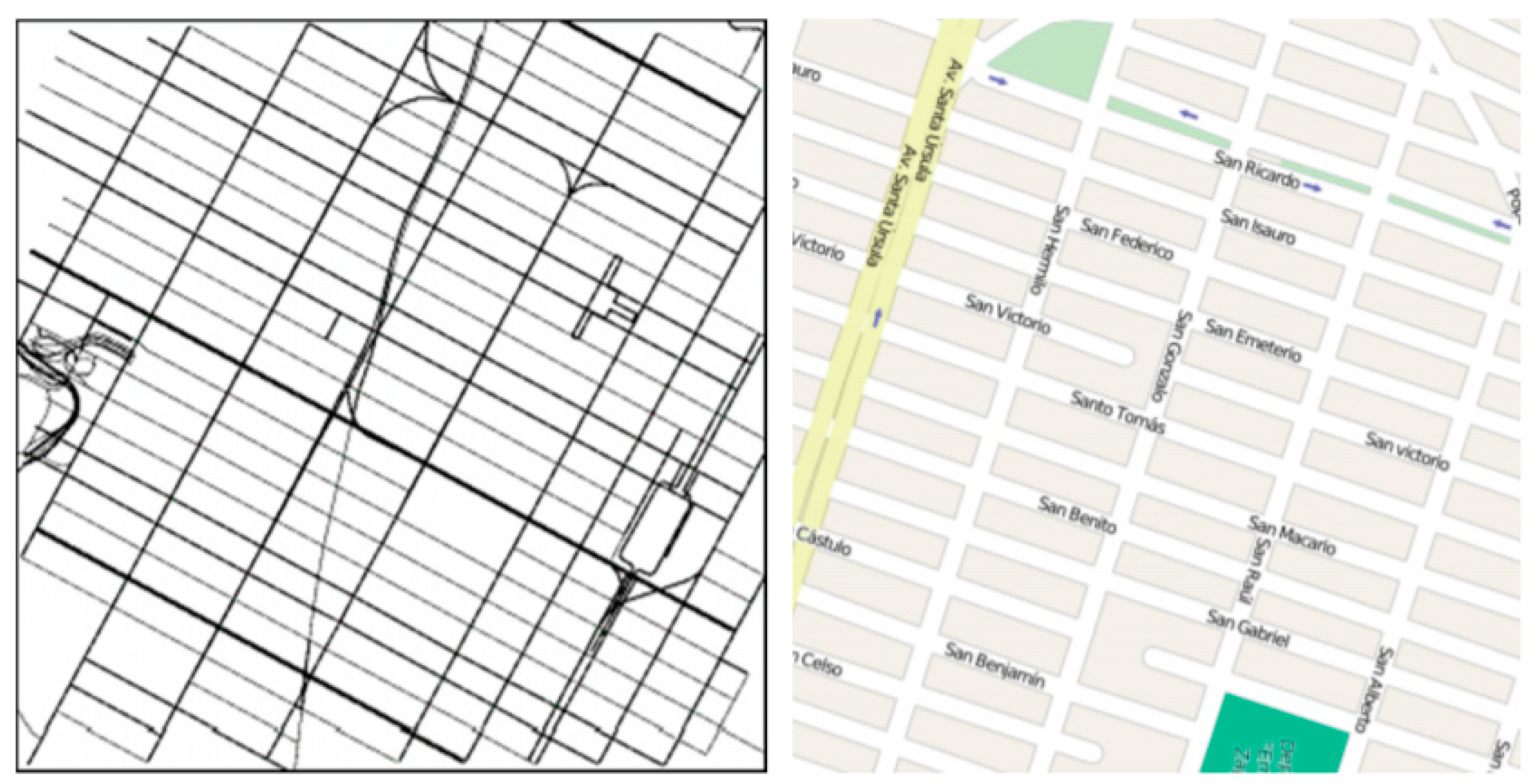
For the simulations, the test space was set to km2 on-road area within the Chicago city road map, as shown in Figure 4. In this map, there are intersections and road segments. We thought about the obstacles among all the road segments wherever no line-of-sight (LOS) was experienced. As represented in Table 3, 350 vehicle nodes were used in the simulations. The typical speed of considered vehicular nodes was in the range of 40–100 km/h.
4.1. Simulation Results
In this section, the simulation results of ISR are discussed in terms of the packet delivery ratio (PDR) and end-to-end delay with increasing numbers of vehicle nodes in the network and different speeds for vehicles. The elaborated description of the considered metrics is as follows. The PDR is defined as the ratio of data packets successfully received at the destination over a total number of packets that were sent from the source vehicle. It showed a successful transmission rate of the routing protocol. The end-to-end delay is defined as the how much time the protocol took to send data to the destination from the source, including processing at each intermediate vehicular node. Basically, it is the sum of sending buffer time, retransmission, medium access delay due to interface queue, propagation delay, and relay selection delay. Hop link disconnection is defined as the failure of message transmission during one hop communication in any forwarding path. The data throughput is defined as the amount of data successfully moved from source to destination per unit time. It is measured in bits per second for each vehicular node involved as source node in communication in the overall vehicular network implementation.
4.1.1. Number of Nodes Analysis
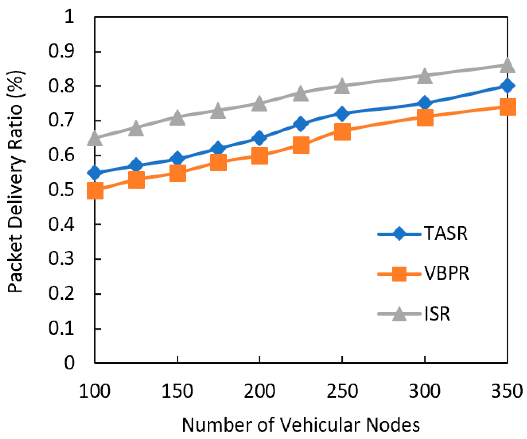
The first simulation result had increasing numbers of vehicle nodes to analyze the data delivery ratio of the proposed routing protocol, and we compared the results with a clustering protocol, the TASR [24] protocol, and a beacon-based virtual backbone in the VBRP [25]. The TASR protocol is a cluster-based routing protocol, but its cluster heads are present on the corners of its cluster, which became outdated here due to the high mobility of the nodes. On the other hand, the VBRP is a position-based protocol that has a network overhead issue due to the continuous beacon messages in the whole network. Figure 5 shows the PDR comparison in accordance with a different number of vehicle nodes in the network. It also shows the trend that ISR consistently increased data delivery due to the increasing connectivity probability with more vehicles in dense networks. The existing TASR had better results than the VBRP because of the applied cluster mechanism. The VBRP is based on a greedy forwarding mechanism that is not appropriate for VANETs. This was the main reason that VBRP was behind TASR and ISR. The results indicated better results of the proposed protocol tan existing routing protocols. Furthermore, the proposed ISR protocol data delivery ratio increased more due to the increasing connectivity probability with higher traffic density in an urban environment.
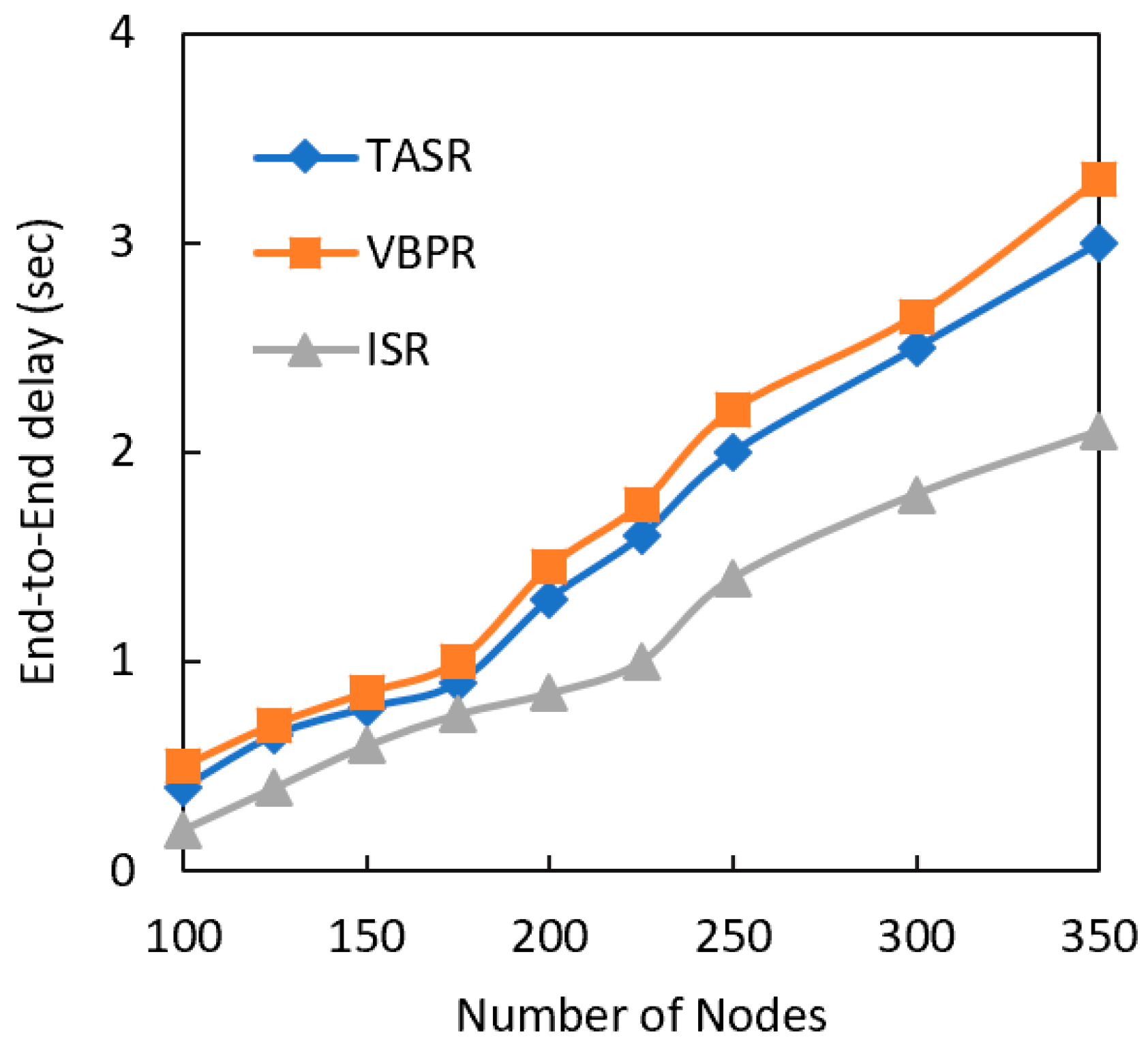
The next performance metric comparatively analyzed with simulation results was end-to-end delay, as shown in Figure 6. The delay of the all considered protocols consistently increased with larger network size due to the routing metric calculations from higher number of nodes in the neighborhood. However, the existing protocols TASR and VBRP had more delay than the proposed ISR protocol. This result also indicated that the clustering protocol TASR had a lower delay than the other protocol VBRP because more traffic had more beacon overhead and the next forwarder selection became difficult. The TASR protocol steeply increased the delay because this protocol initiated the decision based on distance, direction, and signal strength. Although more vehicle nodes centric congestion on road sometime leads to strong signal strength for vehicular communication. However, it results into longer delay due to the information processing at each node in the forwarding vehicles. The proposed ISR protocol addressed this issue by selecting the optimal traffic density road segments.
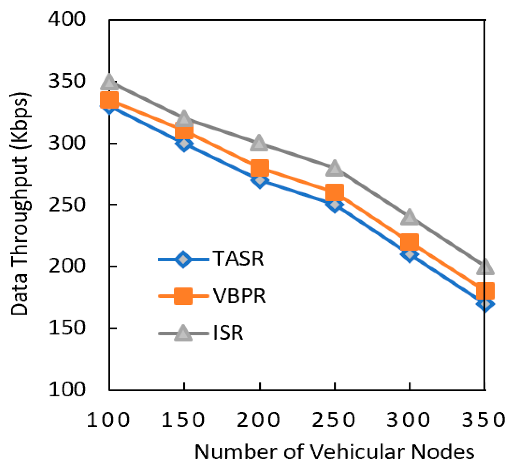
Another performance metric that was analyzed was data throughput, as shown in Figure 7. The data throughput of all the considered protocols consistently decreased due to the routing metric calculation involving more nodes in the network. However, the existing protocols had less data throughput than the proposed protocol. This result also indicated that data throughput decreased when the network had a greater data load in the presence of a greater number of nodes. The TASR protocol steeply decreased throughput because this protocol initiated the decision based on distance, direction, and signal strength. Though the nodes in more congested road sometimes had strong signal strengths, they often had more delay and less throughput due to higher number of vehicle nodes. The proposed protocol addressed this issue by selecting the maximum traffic density road segments, and it thus had better data throughput results.
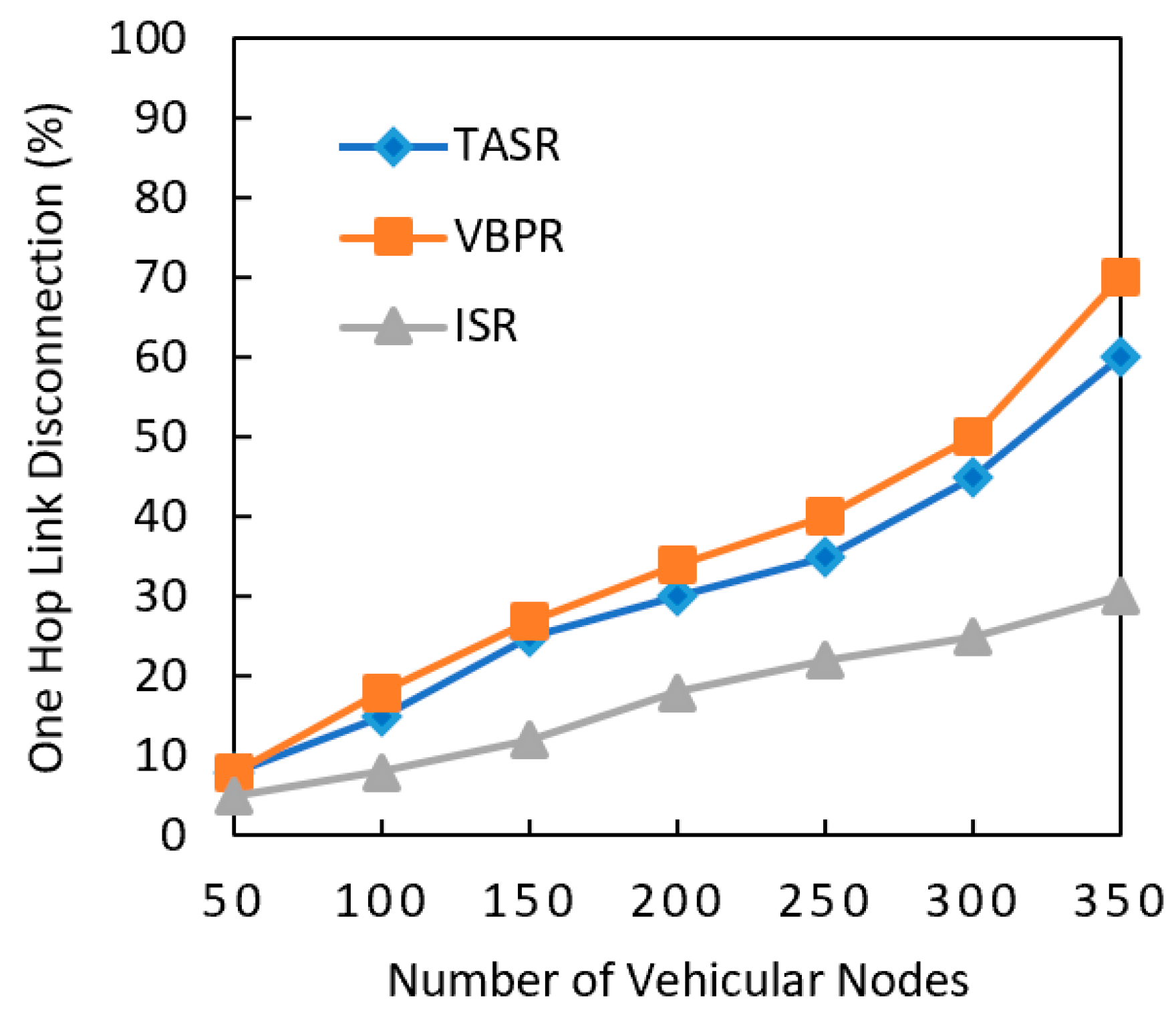
Another analyzed performance metric was one hop link disconnection, as shown in Figure 8. It can be clearly observed that one hop link disconnection of ISR was nominal compared to other two existing protocols. It was also observed that with a greater number of nodes, the one hop disconnection increased. However, the one hop disconnection of the proposed ISR protocol consistently increased due to its routing metric calculations and greater amount of nodes in the network. However, the existing protocols had less one hop disconnection than other two existing protocols. This result also indicated that one hop disconnection increased when the network had a greater data load in the presence of a greater number of nodes. The TASR protocol steeply increased in one hop disconnection because this protocol initiated the decision based on distance, direction, and signal strength. although more vehicle nodes centric congestion on roads results into stronger signal strength for vehicular communication. This often leads to longer delay and more one-hop disconnection due to the greater number of vehicle nodes and different vehicle speeds. The proposed protocol addressed this issue by selecting the maximum traffic density road segments, and it had a better percentage of one hop disconnection.
4.1.2. Speed of Vehicle Analysis
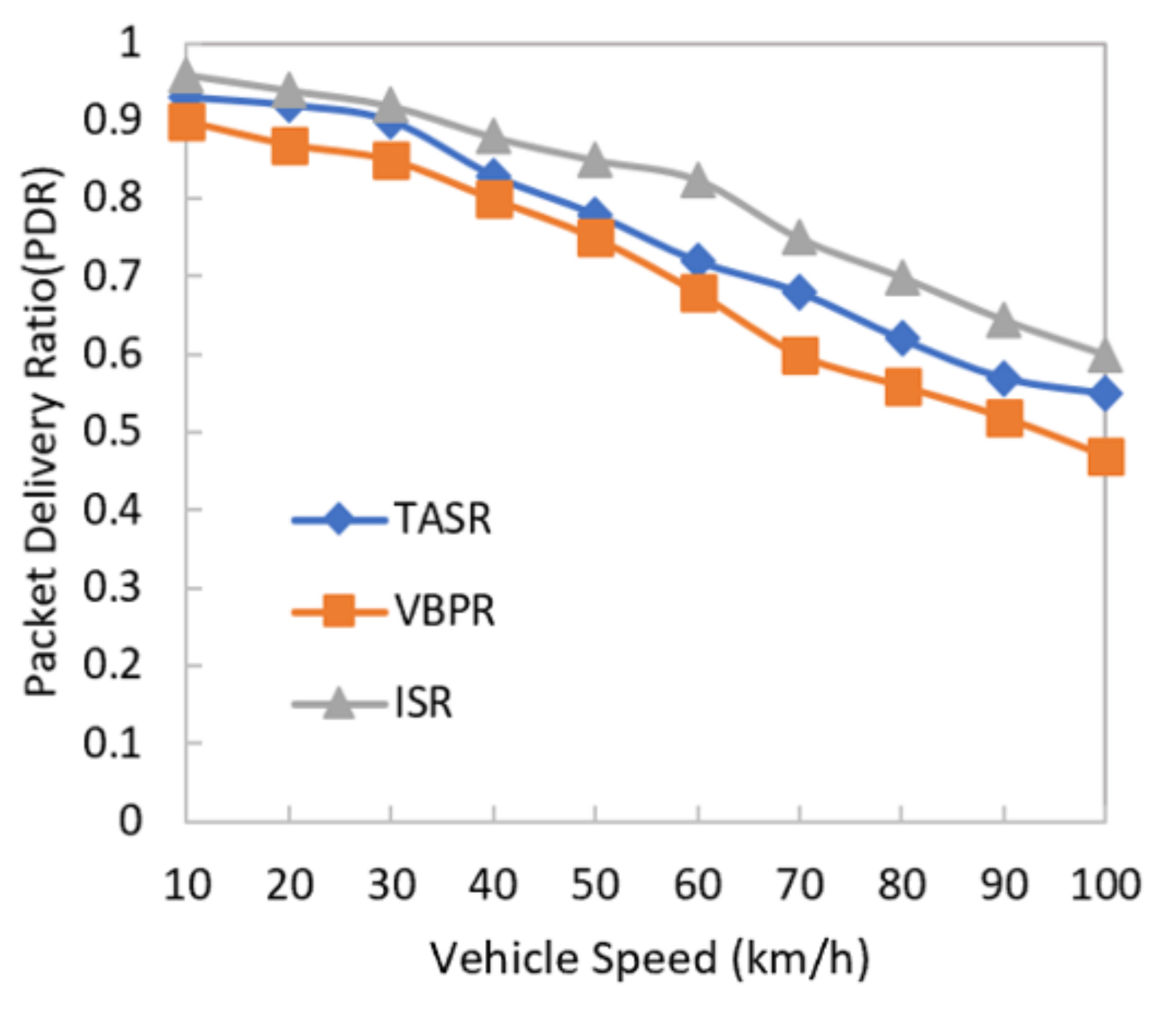
This section shows the analysis of results based on increasing vehicle node speed in terms of the packet delivery ratio and the average delay in the network. Figure 9 shows a comparison of the data delivery ratio of the ISR, TASR and VBRP routing protocols. It can be seen that the increasing vehicle speed resulted into lower PDR in the network for all protocols. However, the proposed ISR had better results due to the removal of beacon messages in the whole network. This mechanism also helped to reduce the consumption of bandwidth and memory to store the neighbor node information. Additionally, the multi-metric protocol supported the protocol to select the appropriate next forwarder node for data delivery towards the destination. On the other hand, the TASR protocol had one mechanism where this protocol determined the distance, direction, and vehicle density metric to select the next forwarder. Additionally, the VBRP used beacon messages in the whole network, which increased the network overhead and led to a packet dropping issue. The high speed also caused the staleness of neighbor node information. The results showed that the proposed protocol had an even better packet delivery ratio when the vehicle node speeds were set to 35 and 40 km/h. The PDR’s decreasing trend indicated that vehicle speed was the cause of low data delivery in the network, but ISR still had better results due to the removal of beacon messages in the whole network for next forwarder node selection. This strategy supported the consumption of less bandwidth than the position-based routing protocols. The TASR protocol also had fewer packet drops than the VBRP due to its multi-metric and clustering strategy. In addition, the high speed caused staleness. The result showed that ISR had better results when the vehicle node speed was set between 50 and 60 km/h in the network, and it gradually decreased when speed reached 100 km/h.
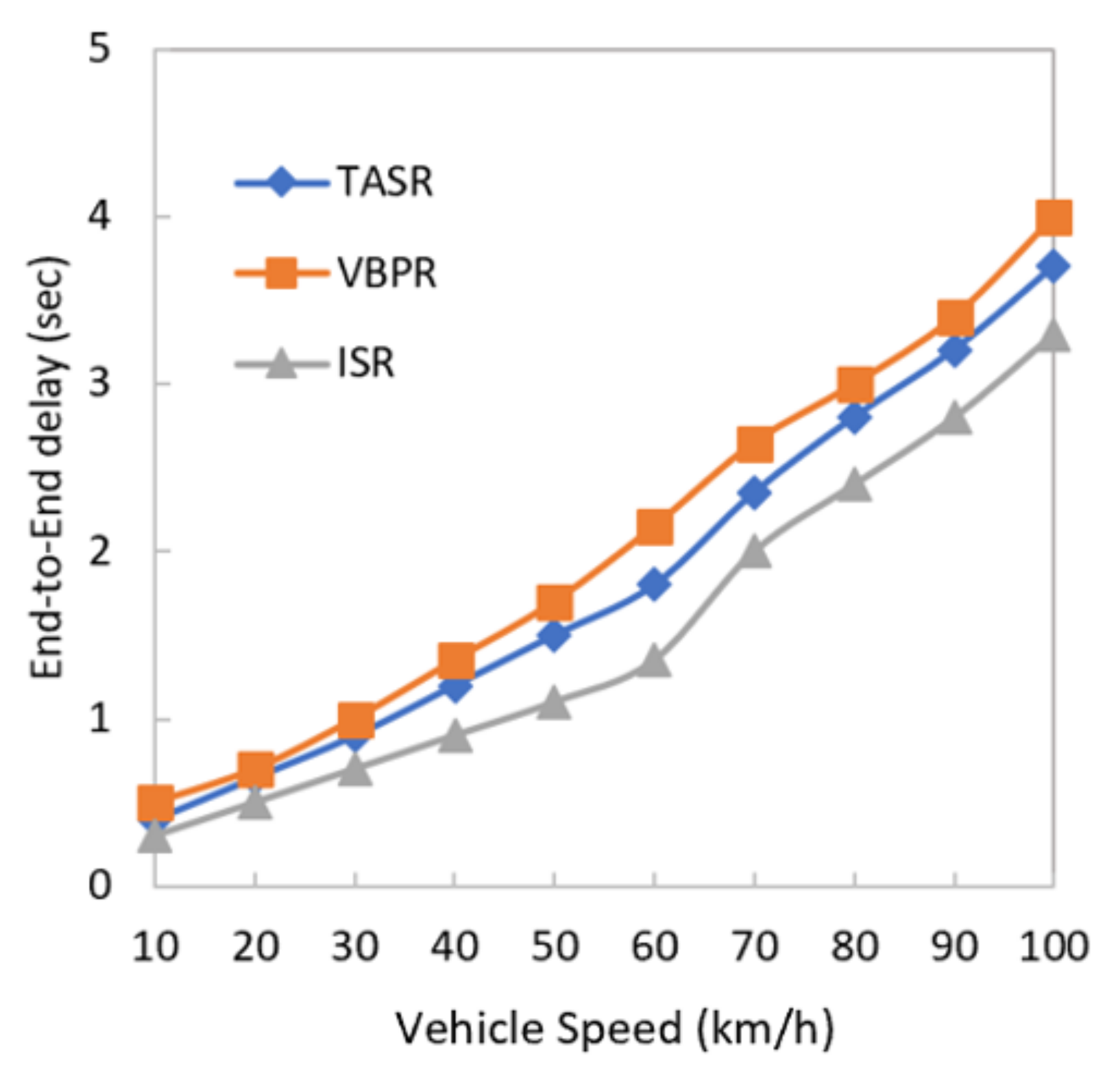
Figure 10 shows the comparison of the average delay results with vehicle speed analysis. The results indicated that the proposed ISR protocol had a lower delay than the TASR and VBRP. Whenever the vehicle speed reached 35 and 40 km/h, the delay was greater due to the high velocity of nodes where the information became outdated and frequent next forwarder selection was needed. Compared to the VBRP, the TASR and ISR had lesser delays. The higher velocity led to more chances for packet dropping. On the other hand, the TASR protocol steeply increased the delay because it initiated the decision based on distance, direction, and vehicle density. although more vehicle nodes centric congestion on road results in better signal strength for vehicular communication. However, it might lead to longer delay in communication due to the higher speed of vehicles and local information processing during forwarding at each node. The proposed protocol addressed this issue by selecting the maximum traffic density segment.
The proposed ISR routing protocol had better results in terms of delay compared to the TASR and VBRP even though the vehicle speed was set at 40–60 km/h. The proposed protocol is the best option for urban areas where vehicle speed lies at a similar normal level. On the contrary, the existing protocols suffered a higher delay when the vehicle speed increased in the network. The TASR clustering protocol had lesser delays than the VBRP because the higher speed of vehicle nodes led to packet dropping and the protocol again checked the neighbor node information to initiate the routing decision. On the other hand, the TASR protocol steeply increased the delay because this protocol initiated the decision based on distance, direction, and vehicle density. although the more vehicle nodes centric congestion on roads results in stronger signal strength for vehicular communication. However, the scenario might lead to longer delay in communication due to the channel congestion for accessing the wireless channel during vehicular communication.
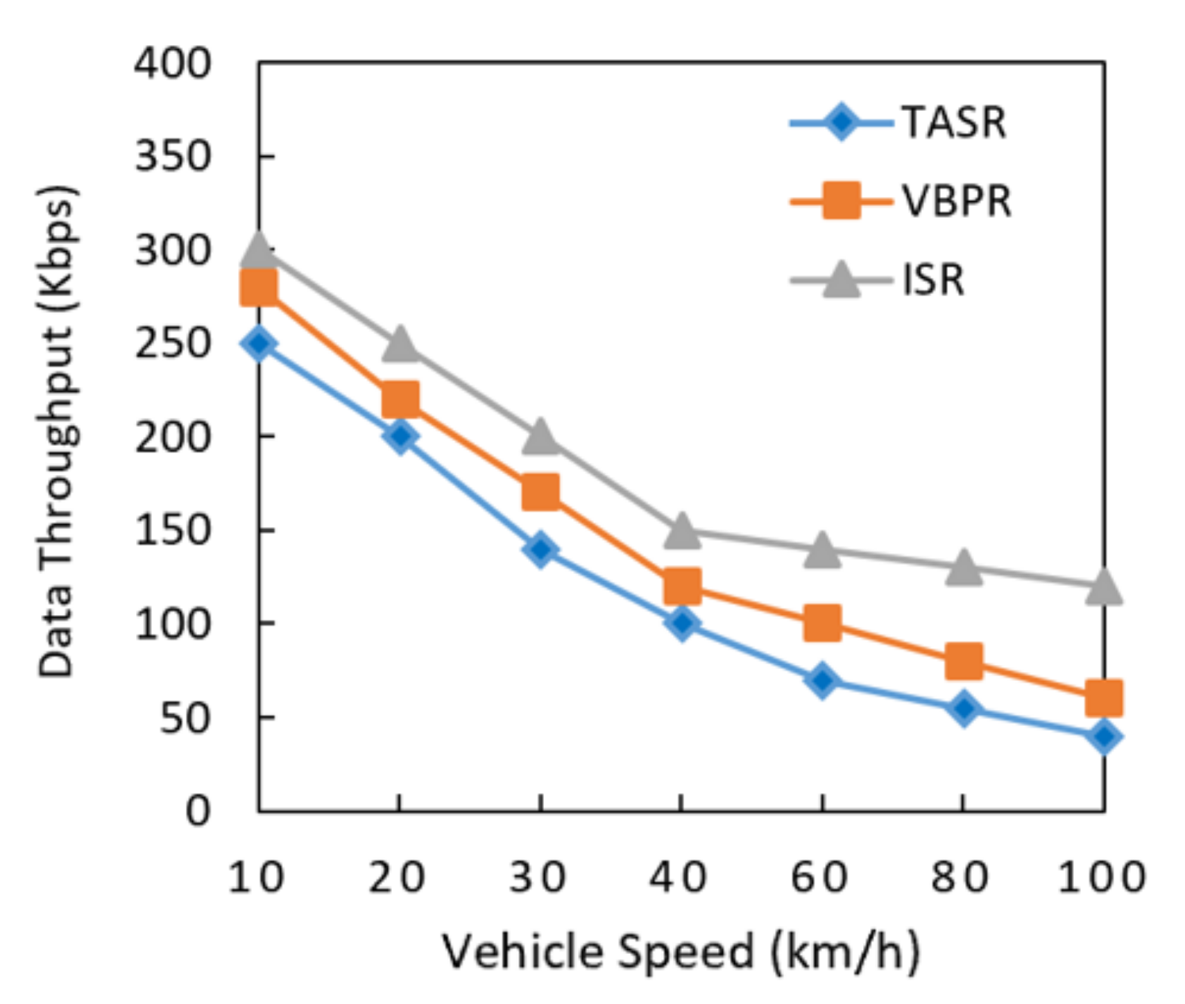
Data throughput was analyzed in the presence of different vehicle velocities, as shown in Figure 11. The data throughput of the proposed ISR protocol consistently decreased due to its routing metric calculations and greater amount of nodes in network. However, the existing protocols had lesser data throughput than the proposed protocol. This result also indicated that the data throughput decreased when the network had a greater data load with different vehicle velocities in the network. The TASR protocol steeply decreased throughput because this protocol initiated the decision based on distance, direction, and signal strength. Although more vehicle nodes centric congestion on roads sometimes show stronger signal strengths for communication. However, longer delay and lesser throughput are some other network challenges due to the different vehicle velocities on roads. The proposed protocol addressed this issue by selecting the maximum traffic density road segments, and it had better data throughput results.
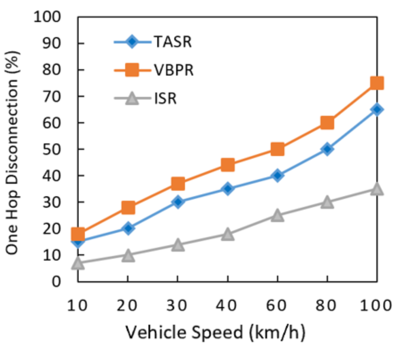
One hop disconnection, as shown in Figure 12, was analyzed in the presence of different vehicle velocities. It can be clearly observed that the one hop link disconnection of ISR was nominal, as compared to other two existing protocols. It was also observed that with different vehicle node speeds, the one hop disconnection increased. However, the one hop disconnection of the proposed ISR protocol consistently increased due to its routing metric calculations and greater amount of nodes in the network. However, the ISR protocol has shown lesser one-hop disconnections than the other two existing protocols. This result also indicated that one hop disconnection increased when the network had a greater data load in different vehicles speeds. The TASR protocol had a steeply increased one hop disconnection because this protocol initiated the decision based on distance, direction, and signal strength. Although the more vehicle nodes centric congested roads have strong signal strengths for communication, however, in this network environment longer delay and more one-hop disconnections are other issues considering different vehicle speeds. The proposed protocol addressed this issue by selecting the maximum traffic density road segments, and it had a lower percentage of one hop disconnections.
It is noteworthy, as shown in Table 4, that the ISR protocol outperformed by 0.68% in terms of the PDR, 5.6% in delay, 16% in throughput, and 18% in one hop disconnections in the presence of different numbers of nodes. On the other hand, in the consideration of higher vehicle speed, the ISR protocol outperformed by 71% in terms of PDR, 5.8 % terms of delay, 38% in data throughput, and 24% in one hop disconnections, as shown in Table 4 and Table 5. We agree that performance of the proposed framework was very close to the considered literature techniques. However, it can be highlighted that the overall performance benefits of the proposed framework are significant and visible for larger network sizes or with higher numbers of nodes and increasing vehicles speeds. Therefore, we believe that these performance improvements will be considerable in realistic traffic environments.
5. Conclusions and Future Work
In this paper, we investigated the existing routing protocol limitations and designed an efficient, stable, and robust routing protocol for VANETs. The existing routing protocols have suffered in terms of dis-connectivity, delay, lower throughput, packet drop, and delivery issues for urban areas due to network dynamics, unpredictable topologies, and the high mobility of nodes. A critical examination of these limitations led to the design of ISR based on traffic density, distance, and the direction of nodes for the next forwarder and route selection. ISR was simulated using a network simulator, and the performance of the protocol was compared with existing routing protocols. The simulation results showed that ISR had a higher data delivery ratio, a lower delay, a higher throughput, and less one-hop disconnections in the scenario of a growing number of vehicular nodes and increasing vehicle speed. The research work was carried out to find the solutions of the problems that were discussed in the literature review. It was found that research regarding beaconless geographical routing protocols still has a long way to go. In the future, we will work towards drone-enabled vehicular ad-hoc networks to enhance the routing and traffic services in real-time traffic environments. How the drone communication framework could benefit on road vehicular traffic information dissemination will be another quest of our future research [28].
Author Contributions
Conceptualization, K.N.Q.; formal analysis, F.U.I.; investigation, F.U.I.; methodology, F.U.I.; resources, F.U.I.; supervision, K.N.Q., O.K.; validation, A.K., J.L.; writing, K.N.Q.; review and editing, O.K., J.L. All authors have read and agreed to the published version of the manuscript.
Funding
This research was funded by Bahria University, Islamabad Campus.
Acknowledgments
The research work is also supported by and Nottingham Trent University, UK.
Conflicts of Interest
The authors declare no conflict of interest.
References
- Fahad, M.; Aadil, F.; Khan, S.; Shah, P.A.; Muhammad, K.; Lloret, J.; Wang, H.; Lee, J.W.; Mehmood, I. Grey wolf optimization based clustering algorithm for vehicular ad-hoc networks. Comput. Electr. Eng. 2018, 70, 853–870. [Google Scholar] [CrossRef]
- Kumar, N.; Rodrigues, J.J.; Lloret, J.; Dua, A. Replication-aware data dissemination for vehicular ad hoc networks using location determination. Mob. Netw. Appl. 2015, 20, 251–267. [Google Scholar] [CrossRef]
- Aliyu, A.; El-Sayed, H.; Abdullah, A.H.; Alam, I.; Li, J.; Prasad, M. Video streaming in urban vehicular environments: Junction-aware multipath approach. Electronics 2019, 8, 1239. [Google Scholar] [CrossRef] [Green Version]
- Aujla, G.S.; Chaudhary, R.; Kumar, N.; Rodrigues, J.J.; Vinel, A. Data offloading in 5g-enabled software-defined vehicular networks: A stackelberg-game-based approach. IEEE Commun. Mag. 2017, 55, 100–108. [Google Scholar] [CrossRef]
- Aljeri, N.; Boukerche, A. A Dynamic MAP Discovery and Selection Scheme for Predictive Hierarchical MIPv6 in Vehicular Networks. IEEE Trans. Veh. Technol. 2019, 69, 793–806. [Google Scholar] [CrossRef]
- Alves Junior, J.; Wille, E.C. Routing in Vehicular Ad Hoc Networks: Main Characteristics and Tendencies. J. Comput. Netw. Commun. 2018, 1302123, 1–10. [Google Scholar] [CrossRef]
- Cao, Y.; Kaiwartya, O.; Aslam, N.; Han, C.; Zhang, X.; Zhuang, Y.; Dianati, M. A trajectory-driven opportunistic routing protocol for VCPS. IEEE Trans. Aerosp. Electron. Syst. 2018, 54, 2628–2642. [Google Scholar] [CrossRef] [Green Version]
- Kaiwartya, O.; Kumar, S. Enhanced Caching for Geocast Routing in Vehicular Ad Hoc Network. In Intelligent Computing, Networking, and Informatics; Mohapatra, D.P., Patnaik, S., Eds.; Advances in Intelligent Systems and Computing; Springer: New Delhi, India, 2014; Volome 243. [Google Scholar]
- Qureshi, K.N.; Idrees, M.M.; Lloret, J.; Bosch, I. Self-Assessment Based Clustering Data Dissemination for Sparse and Dense Traffic Conditions for Internet of Vehicles. IEEE Access 2020, 8, 10363–10372. [Google Scholar] [CrossRef]
- Lai, W.K.; Tai, C.K.; Wu, M.J. CAME, connectionless approach for vehicular ad hoc networks in metropolitan environments. Wirel. Pers. Commun. 2016, 91, 403–418. [Google Scholar] [CrossRef]
- Hassan, A.N.; Abdullah, A.H.; Kaiwartya, O.; Cao, Y.; Sheet, D.K. Multi-metric geographic routing for vehicular ad hoc networks. Wirel. Netw. 2018, 24, 2763–2779. [Google Scholar] [CrossRef]
- Kaiwartya, O.; Kumar, S. Geocasting in vehicular adhoc networks using particle swarm optimization. In Proceedings of the International Conference on Information Systems and Design of Communication Lisbon, Lisboa, Portugal, 16–17 May 2014; pp. 62–66. [Google Scholar]
- Hassan, A.N.; Abdullah, A.H.; Kaiwartya, O.; Sheet, D.K.; Aliyu, A. Geographic forwarding techniques: Limitations and future challenges in IVC. In Proceedings of the 2017 6th ICT International Student Project Conference (ICT-ISPC), Johor, Malaysia, 23–24 May 2017; pp. 1–5. [Google Scholar]
- Kasana, R.; Kumar, S.; Kaiwartya, O.; Yan, W.; Cao, Y.; Abdullah, A.H. Location error resilient geographical routing for vehicular ad-hoc networks. IET Intell. Transp. Syst. 2017, 11, 450–458. [Google Scholar] [CrossRef] [Green Version]
- Qureshi, K.N.; Abdullah, A.H.; Kaiwartya, O.; Ullah, F.; Iqbal, S.; Altameem, A. Weighted link quality and forward progress coupled with modified RTS/CTS for beaconless packet forwarding protocol (B-PFP) in VANETs. Telecommun. Syst. 2016, 1–16. [Google Scholar] [CrossRef]
- Boussoufa-Lahlah, S.; Semchedine, F.; Bouallouche-Medjkoune, L. Geographic routing protocols for Vehicular Ad hoc NETworks (VANETs): A survey. Veh. Commun. 2018, 11, 20–31. [Google Scholar] [CrossRef]
- Jasper, A.; Paulus, R.; Rathore, S. Improvement of LAR1 Routing Protocol. Procedia Comput. Sci. 2015, 57, 77–83. [Google Scholar] [CrossRef] [Green Version]
- Singh, A.; Kaur, N. Enhanced Bandwidth Efficient Cluster Based Multicasting Protocol in VANETs. In Proceedings of the 2nd International Conference on Recent Advances in Engineering & Computational Sciences (RAECS), Chandigarh, India, 21–22 December 2015; pp. 1–6. [Google Scholar]
- Qureshi, K.N.; Abdullah, A.H.; Lloret, J. Road perception based geographical routing protocol for vehicular ad hoc networks. Int. J. Distrib. Sens. Netw. 2016, 12, 2617480. [Google Scholar] [CrossRef] [Green Version]
- Kaur, K.; Kad, S. Enhanced clustering based AODV-R protocol using Ant Colony Optimization in VANETS. In Proceedings of the 2016 IEEE 1st International Conference on Power Electronics, Intelligent Control. and Energy Systems (ICPEICES), Delhi, India, 4 July 2016; pp. 1–5. [Google Scholar]
- Karimi, R.; Shokrollahi, S. PGRP: Predictive geographic routing protocol for VANETs. Comput. Netw 2018, 141, 67–81. [Google Scholar] [CrossRef]
- Zhang, X.; Cao, X.; Yan, L.; Sung, D.K. A Street-Centric Opportunistic Routing Protocol Based on Link Correlation for Urban VANETs. IEEE Trans. Mob. Comput. 2016, 15, 1586–1599. [Google Scholar] [CrossRef]
- Dharani Kumari, N.V.; Shylaja, B.S. AMGRP: AHP-based Multimetric Geographical Routing Protocol for Urban environment of VANETs. J. King Saud Univ. Comput. Inf. Sci. 2019, 31, 72–81. [Google Scholar] [CrossRef]
- Khan, S.; Alam, M.; Fränzle, M.; Müllner, N.; Chen, Y. A Traffic Aware Segment-based Routing protocol for VANETs in urban scenarios. Comput. Electr. Eng. 2018, 68, 447–462. [Google Scholar] [CrossRef]
- Ji, X.; Yu, H.; Fan, G.; Fu, W. A Reliable and Efficient Routing Protocol Based on Virtual Backbone in Vehicular Ad Hoc Networks. IEICE Trans. Commun. 2018, E102.B, 298–305. [Google Scholar] [CrossRef]
- Kumar, N.; Misra, S.; Rodrigues, J.J.; Obaidat, M.S. Coalition games for spatio-temporal big data in Internet of Vehicles environment: A comparative analysis. IEEE Internet Things J. 2015, 2, 310–320. [Google Scholar] [CrossRef]
- Kumar, N.; Kumar, M.; Patel, R.B. Capacity and interference aware link scheduling with channel assignment in wireless mesh networks. J. Netw. Comput. Appl. 2011, 34, 30–38. [Google Scholar] [CrossRef]
- Lin, C.; He, D.; Kumar, N.; Choo, K.K.R.; Vinel, A.; Huang, X. Security and privacy for the internet of drones: Challenges and solutions. IEEE Commun. Mag. 2018, 56, 64–69. [Google Scholar] [CrossRef]
Figure 1.
Trajectory and segment formation scenario for the improved road segment-based geographical routing (ISR) protocol.
Figure 1.
Trajectory and segment formation scenario for the improved road segment-based geographical routing (ISR) protocol.

Figure 2.
Flowchart of head node selection.

Figure 3.
Flowchart of information dissemination-centric routing process.

Figure 4.
Fragmented city map of Chicago city.

Figure 5.
Packet delivery ratio with increasing number of vehicular nodes in the network.

Figure 6.
Comparison of end-to-end delay with increasing number of vehicular nodes.

Figure 7.
Comparison of data throughput with increasing number of vehicular nodes.

Figure 8.
Comparison of one-hop link disconnection with increasing number of nodes.

Figure 9.
Comparison of packet delivery ratio with increasing vehicle speed.

Figure 10.
Comparison of end-to-end delay with increasing vehicle speed.

Figure 11.
Comparison of data throughput with increasing vehicle speed.

Figure 12.
Comparison of one-hop link disconnection with increasing vehicle speed.


Table 1.
Parameters for geographical routing protocols. PGRP: perception-based geographical routing protocol; AODV-R: ad hoc demand distance vector reliability; AMGR: analytical hierarchical process (AHP)-based multi-metric geographical routing; TASR: traffic-aware segment-based routing; and VBRP: virtual backbone routing protocol.
| S/N | Protocol Name | Year | Direction | Position | Link Quality | Velocity | Distance | Road Topology | Traffic Density |
|---|---|---|---|---|---|---|---|---|---|
| 1 | MLAR1 [17] | 2015 | × | × | × | × | × | × | |
| 2 | EBECM [18] | 2015 | × | × | × | × | |||
| 3 | PGRP [19] | 2016 | × | × | × | × | × | ||
| 4 | AODV-R [20] | 2016 | × | × | × | × | × | ||
| 5 | PGR [21] | 2016 | × | × | × | × | |||
| 6 | SRPE [22] | 2016 | × | × | × | × | |||
| 7 | AMGR [23] | 2017 | × | × | × | × | |||
| 9 | TASR [24] | 2018 | × | × | × | × | × | ||
| 10 | VBRP [25] | 2018 | × | × | × | × |
Table 2.
Notations with description.
| Notations | Description |
|---|---|
| s, d | IDs of the source nodes and destination nodes |
| Snext | Next Segment |
| HNi | Head Nodes for segment i |
| NSHi | Next segment Head Node where i = 1, 2, 3, …, n |
| Ss | Segment where source s is located |
| Sd | Segment where destination d is located |
| RD | Route Discovery packet |
| ni | Intermediate node |
Table 3.
Major simulation setup parameters. CBR: constant bit rate; SUMO-MOVE: simulation for urban mobility-mobility model generator for VANETs.
Table 3.
Major simulation setup parameters. CBR: constant bit rate; SUMO-MOVE: simulation for urban mobility-mobility model generator for VANETs.
| Parameter | Value |
|---|---|
| Network Simulator | NS-2.34 |
| Simulation Area | 2 km × 2 km |
| Traffic type | CBR |
| Simulation Time | 500 s |
| MAC protocol | IEEE 802.11p |
| No of Vehicle Nodes | 100–350 |
| Packet Size | 512 bytes |
| Transmission range | 300 m |
| Vehicle speed | 10–100 km/h |
| Mobility Model | SUMO-MOVE |
Table 4.
Analysis of the packet delivery ratio (PDR), delay, throughput, and one hop disconnection.
| PDR | End-to-End Delay | Data Throughput | One Hop Disconnection | |||||||||
|---|---|---|---|---|---|---|---|---|---|---|---|---|
| No Nodes | ISR | VBRP | TASR | ISR | VBRP | TASR | ISR | VBRP | TASR | ISR | VBRP | TASR |
| 0.63 | 0.5 | 0.53 | 0.1 | 0.4 | 0.5 | 350 | 335 | 330 | 5 | 8 | 8 | |
| 0.64 | 0.52 | 0.54 | 0.2 | 0.5 | 0.7 | 320 | 310 | 300 | 8 | 18 | 15 | |
| 0.65 | 0.56 | 0.55 | 0.5 | 0.6 | 1 | 300 | 280 | 270 | 12 | 27 | 25 | |
| 0.65 | 0.60 | 0.6 | 0.6 | 0.9 | 1.3 | 280 | 260 | 250 | 18 | 34 | 30 | |
| 0.66 | 0.62 | 0.62 | 0.8 | 1 | 1.5 | 240 | 220 | 210 | 22 | 40 | 35 | |
| 0.69 | 0.65 | 0.66 | 1 | 1.8 | 1.7 | 200 | 180 | 170 | 25 | 50 | 45 | |
| 0.72 | 0.70 | 0.64 | 1.5 | 2.6 | 2 | 160 | 120 | 100 | 30 | 70 | 60 | |
| 0.81 | 0.73 | 0.66 | 1.7 | 3 | 2.5 | 140 | 119 | 90 | 31 | 65 | 65 | |
| 0.86 | 0.75 | 0.69 | 2 | 3.2 | 2.9 | 120 | 117 | 80 | 32 | 60 | 70 | |
| Vehicle Velocity | 0.95 | 0.9 | 0.92 | 0.2 | 0.5 | 0.4 | 300 | 280 | 250 | 7 | 18 | 15 |
| 0.94 | 0.88 | 0.90 | 0.4 | 0.6 | 0.5 | 250 | 220 | 200 | 10 | 28 | 20 | |
| 0.91 | 0.85 | 0.88 | 0.6 | 1 | 1.2 | 200 | 170 | 140 | 14 | 37 | 30 | |
| 0.88 | 0.8 | 0.85 | 0.9 | 1.3 | 2.2 | 150 | 120 | 100 | 18 | 44 | 35 | |
| 0.85 | 0.77 | 0.80 | 1 | 1.8 | 2.5 | 140 | 100 | 70 | 25 | 50 | 40 | |
| 0.77 | 0.70 | 0.75 | 1.2 | 2.2 | 3 | 130 | 80 | 55 | 30 | 60 | 50 | |
| 0.72 | 0.65 | 0.70 | 1.8 | 2.5 | 3.3 | 120 | 60 | 40 | 35 | 75 | 65 | |
| 0.68 | 0.60 | 0.65 | 2.2 | 3.1 | 3.5 | 110 | 50 | 35 | 33 | 70 | 70 | |
| 0.66 | 0.50 | 0.55 | 2.9 | 4 | 3.7 | 100 | 40 | 30 | 30 | 65 | 75 | |
Table 5.
Performance of ISR against competitive protocols with increasing ↑ or decreasing ↓ trend.
| Protocols | Performance of ISR against Benchmark Protocols | |||
|---|---|---|---|---|
| ISR | PDR | End-to-End Delay | Throughput | One Hop Disconnection |
| With number of nodes | 0.68 % ↑ | 5.6%↓ | 16%↑ | 18%↓ |
| With Vehicle Speed | 71%↑ | 5.8%↓ | 38%↑ | 24%↓ |
© 2020 by the authors. Licensee MDPI, Basel, Switzerland. This article is an open access article distributed under the terms and conditions of the Creative Commons Attribution (CC BY) license (http://creativecommons.org/licenses/by/4.0/).
Share and Cite
MDPI and ACS Style
Qureshi, K.N.; Islam, F.U.; Kaiwartya, O.; Kumar, A.; Lloret, J. Improved Road Segment-Based Geographical Routing Protocol for Vehicular Ad-hoc Networks. Electronics 2020, 9, 1248. https://doi.org/10.3390/electronics9081248
AMA Style
Qureshi KN, Islam FU, Kaiwartya O, Kumar A, Lloret J. Improved Road Segment-Based Geographical Routing Protocol for Vehicular Ad-hoc Networks. Electronics. 2020; 9(8):1248. https://doi.org/10.3390/electronics9081248
Chicago/Turabian StyleQureshi, Kashif Naseer, Farooq Ul Islam, Omprakash Kaiwartya, Arvind Kumar, and Jaime Lloret. 2020. "Improved Road Segment-Based Geographical Routing Protocol for Vehicular Ad-hoc Networks" Electronics 9, no. 8: 1248. https://doi.org/10.3390/electronics9081248
Note that from the first issue of 2016, this journal uses article numbers instead of page numbers. See further details here.