Review

A Survey on Reconfigurable Microstrip Filter–Antenna Integration: Recent Developments and Challenges

by
Yuxiang Tu
1,
Yasir I. A. Al-Yasir
1,*,
Naser Ojaroudi Parchin
1,
Ahmed M. Abdulkhaleq
1,2 and
Raed A. Abd-Alhameed
1,3
1
Biomedical and Electronics Engineering, Faculty of Engineering and Informatics, University of Bradford, Bradford BD7 1DP, UK
2
SARAS Technology Limited, Leeds LS12 4NQ, UK
3
Department of Communication and Informatics Engineering, Basra University College of Science and Technology, Basra 61004, Iraq
*
Author to whom correspondence should be addressed.
Electronics 2020, 9(8), 1249; https://doi.org/10.3390/electronics9081249
Submission received: 15 June 2020 / Revised: 21 July 2020 / Accepted: 29 July 2020 / Published: 4 August 2020
(This article belongs to the Special Issue Recent Advances in Antenna Design for 5G Heterogeneous Networks)

Abstract

:
Reconfigurable and tunable radio frequency (RF) and microwave (MW) components have become exciting topics for many researchers and design engineers in recent years. Reconfigurable microstrip filter–antenna combinations have been studied in the literature to handle multifunctional tasks for wireless communication systems. Using such devices can reduce the need for many RF components and minimize the cost of the whole wireless system, since the changes in the performance of these applications are achieved using electronic tuning techniques. However, with the rapid development of current fourth-generation (4G) and fifth-generation (5G) applications, compact and reconfigurable structures with a wide tuning range are in high demand. However, meeting these requirements comes with some challenges, namely the increased design complexity and system size. Accordingly, this paper aims to discuss these challenges and review the recent developments in the design techniques used for reconfigurable filters and antennas, as well as their integration. Various designs for different applications are studied and investigated in terms of their geometrical structures and operational performance. This paper begins with an introduction to microstrip filters, antennas, and filtering antennas (filtennas). Then, performance comparisons between the key and essential structures for these aspects are presented and discussed. Furthermore, a comparison between several RF reconfiguration techniques, current challenges, and future developments is presented and discussed in this review. Among several reconfigurable structures, the most efficient designs with the best attractive features are addressed and highlighted in this paper to improve the performance of RF and MW front end systems.

1. Introduction

The increasing demand for compact, simple, and efficient transceivers continues to impact the development of microwave (MW) and radio frequency (RF) applications [1,2,3,4,5]. Some of the essential elements in such devices are the planar antennas and filters [6,7,8,9], which significantly affect the whole performance of the wireless communication systems. Generally, RF interference is a big issue in the current and future wireless systems, such as the green RF front ends and wideband applications [10,11]. Microstrip bandpass filters (BPFs) are commonly used in several applications, mainly in RF and MW wireless communications, due to their effective role in suppressing interference and noise signals [12,13,14]. Recently, the office of communications (Ofcom) has identified a low bandwidth at 700 MHz, mid bandwidth (3.4–3.8 GHz), and an upper millimeter-wave bandwidth (24.25–27.5 GHz) for possible use with fifth-generation (5G) systems [15]. However, microstrip BPFs are utilized to attenuate the harmonic signals in fourth-generation (4G) and 5G applications [16,17,18,19,20]. For microstrip BPFs, the number of poles and zeros, input and output external quality factors, coupling coefficients, and the configuration of the resonators are important parameters that define the filter performance [21]. Most microstrip filter miniaturization approaches aim to analyze, control, or optimize these parameters [22]. Additionally, several design techniques have been introduced in the literature, such as stepped-impedance resonator (SIR), combline, open-ring, coupled-line, and stub impedance filters [23,24,25,26,27].
On the other hand, reconfigurability can also be utilized using RF electronic components, such as varactors and PIN diodes, which allow for the current distribution on the patches to be modified and then for the reflection coefficient and radiation patter characteristics to be adapted. Micro-electro-mechanical switches (MEMS) can also be considered, however these involve additional costs and extra circuits. In recent years, several reconfigurable microstrip BPFs have been introduced [28,29,30,31,32,33,34,35,36]. However, with the rapid development of current 4G and 5G applications, compact, efficient, and reconfigurable planar filters with a wide tuning range will be urgently needed [37].
In addition to reconfigurable microstrip filters, frequency-reconfigurable microstrip antennas have been investigated and developed for many years to provide important features to enhance the innovation and development of RF systems [38,39,40,41]. Another important factor to be considered by antenna designers and researchers these days, especially when designing antennas for mobile devices, is the geometrical size and design complexity of the RF elements. Therefore, antenna miniaturization techniques are continuously under review and study by many researchers and engineers. However, there are always new developments and updates in the literature related to these aspects. Due to the high demand for very small structures, the construction of more compact components is required, while the gain and radiation pattern properties should be maintained at the same time and for the same configuration [38]. Compact frequency-reconfigurable microstrip antennas have been introduced for several applications, such as mobile communication devices. Furthermore, these antennas are also needed for other applications, such as global systems for mobile communication (GSM), digital communication systems (DCS), personal communication systems (PCS), universal mobile telecommunication systems (UMTS), Bluetooth, wireless local area networks (LAN), and long-term evolution (LTE) [42,43,44,45,46,47,48,49,50,51,52].
In recent years, the microstrip filter–antenna integration designs have become some of the most desired structures because of their low profile, compact size, light weight, and ease of fabrication [53,54,55,56,57,58,59,60,61,62,63,64,65,66,67,68,69,70,71]. Microstrip filtering antennas are also beneficial because they can be printed directly onto the dielectric substrate materials [53]. Filtering antenna designs have many applications, mostly in modern wireless communication systems, where filtering and efficient radiation pattern responses can be obtained simultaneously [55]. Furthermore, reconfigurable microstrip filtering antennas have attracted increasing interest nowadays as they can deliver more efficient and multiple functionalities [72,73,74,75,76,77,78,79,80,81,82,83,84,85,86]. These designs do not implement microstrip antennas and filters separately, rather the filter is loaded onto the radiating patch instead, resulting in more compact structures and improving the entire performance of the RF and MW systems.
Few review papers discuss the reconfigurable filtering antenna designs that have been presented in the literature [87,88,89]. In [87,88], the papers focus on passive filtering antenna configurations with ultra-wideband characteristics. These papers do not present an extensive up-to-date review of the recent technologies utilized to implement the RF components (filters, antennas, and filtennas). In [89], a review of various integrated reconfigurable filter and antenna combinations was presented in 2015. Many design techniques have been investigated in recent years, achieving structures with compact sizes and simple configurations, which need further study.
Unlike other review papers, up-to-date reconfigurable microstrip filters and antennas and their integration are investigated in this paper by focusing on the latest development and design challenges for these components. According to the literature review carried out in this paper, performance comparisons between the key and essential reconfigurable structures are also presented and discussed. We point out the most efficient designs with the most attractive features for researchers and engineers for reconfigurable microstrip filters, antennas, and filtering antennas (filtennas). Additionally, Figure 1 shows a graphical summary of the reviewed design techniques in this paper. This manuscript is organized as follows. Section 2 discusses the latest updates in the reconfigurable microstrip filter design. Section 3 presents and reviews some efficient frequency-reconfigurable microstrip antennas. Section 4 surveys filter–antenna integration, as well as reconfigurable filtering antennas. All these sections are followed by performance comparisons to summarize the main characteristics and advantages for each structure. Section 5 provides a comparison between several RF reconfiguration switches. Section 6 presents the main challenges and recommendation for future research work. Finally, Section 6 summarizes the conclusions of our review.

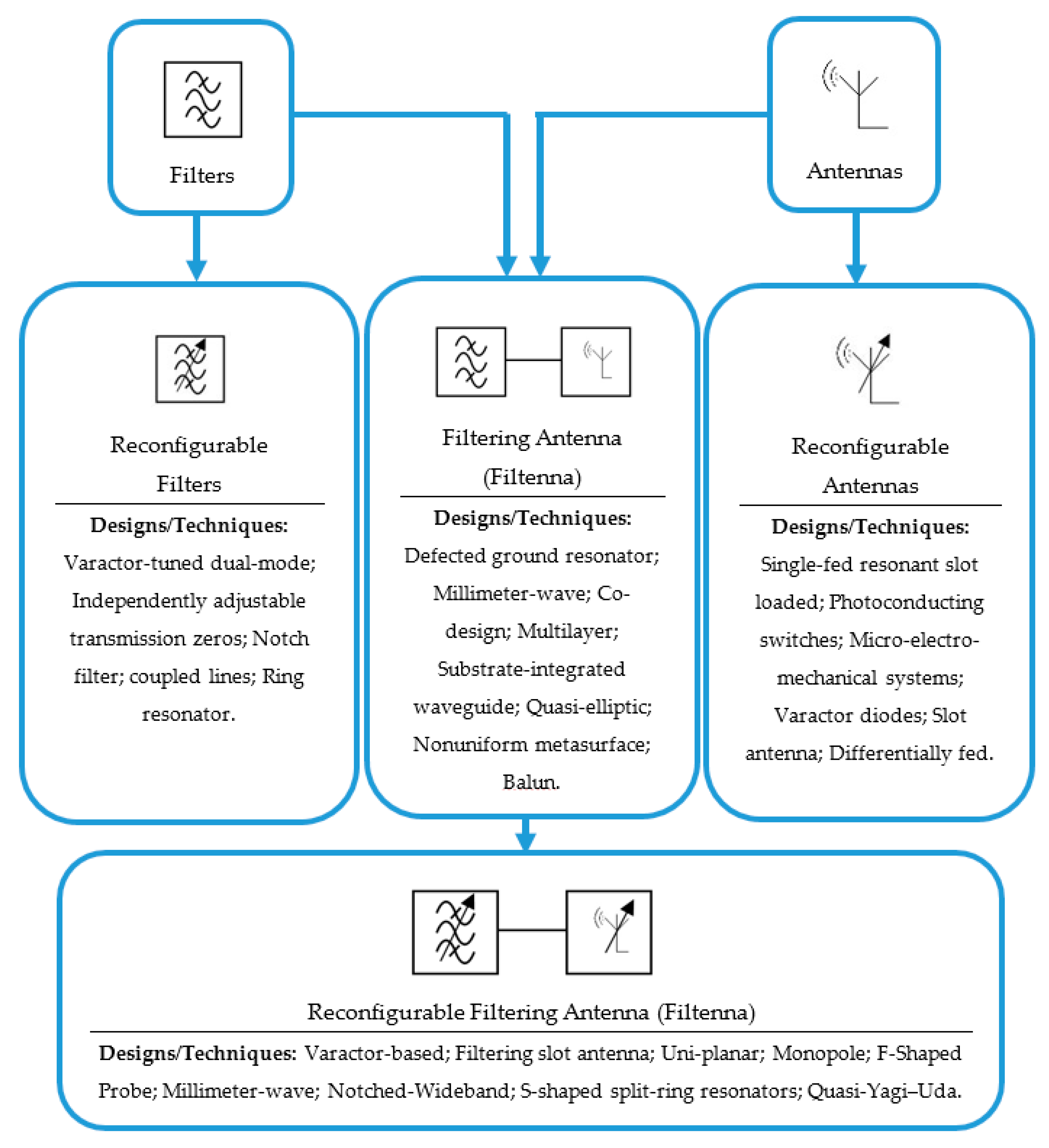
2. Reconfigurable Microstrip Filters

In recent years, several reconfigurable BPFs have been introduced [28,29,30,31,32,33,34,35,36,37]. A reconfigurable microstrip BPF using a varactor diode was designed and analyzed to achieve a constant impedance bandwidth in [29]. Reconfigurability is obtained by tuning the resonance frequencies for both the odd and even modes, where there is no mutual coupling between these two modes. Figure 2 shows the proposed tunable BPF with the obtained performance. The practical BPF performance depicts a good roll-off skirt on the low edge of the transmission band, with an insertion loss of less than 2.2 dB and a return loss of more than 10 dB. A 2.2–22.0 V reverse bias voltage is applied across the varactor diode to achieve a tuning rate of 40% for the 0.60–1.0 GHz range, with 91 MHz impedance bandwidth for all configurations.
In [30], a reconfigurable microstrip BPF utilizes two varactors to tune two finite transmission zeros (TZs). The center frequency and the bandwidth are controlled to cover a wide range of about 600 MHz (1.4 GHz to 2.0 GHz) by altering the reverse bias voltage across the varactors (as seen in Figure 3). The measurement results show that the filter has an insertion loss of less than 4 dB, a return loss of more than 18 dB, and a fractional bandwidth of about 10%. A stopband rejection level of more than 25 dB is obtained by using the two transmission zeros. A 0.21–30.02 V bias voltage is applied across the diodes to tune the resonance frequency. In [31], a compact tunable planar BPF with a constant fractional bandwidth is introduced. By increasing the reverse bias voltage across the switches, the center frequency of the filter is tuned from 3.4 GHz to 3.8 GHz, with a fractional bandwidth of about 11%. The presented tunable filter has the advantages of having a compact size and simple structure, using only one varactor diode switch.
Ebrahimi et al. [32] proposed a notch dual-mode tunable bandstop planar filter using two varactor diodes. The proposed filter is implemented by loading inductive and capacitive coupling into the input and output transmission lines of the microstrip filter. The inductors were designed by using thin inductive strips. As illustrated in Figure 4, the second-order filter has a compact size of 0.13 λg × 0.17 λg and offers a continuous tuning range for the resonance frequency that ranges from 0.8 GHz to 1.1 GHz, with a stopband fractional bandwidth of about 17%. The measurement results show that the filter has 0.9 dB stopband return loss and 0.6 dB passband insertion loss over the entire tuning range. Apart from the other designs, the inductive coupling is achieved using an inductor in the bottom layer of the patch filter. This configuration avoids the need for a more complicated three-layered structure, provides more degrees of freedom in controlling the coupling coefficient factors, and maintains the top layer configuration, resulting in a more compact design.
Moreover, Chen et al. [33] introduced a 2-pole fully tunable planar filter with a small structure, continuous frequency tuning range, and constant impedance bandwidth. Two varactors are utilized to tune the resonance frequency between the high and low resonating modes. The tunable filter has a simple configuration that consists of a pair of reversed biased varactor diodes. Each resonator contains two transmission lines, which are connected together via a varactor diode. A 0.4–18 V bias voltage is applied to provide 0.3–2.4 pF capacitance. The tuning range for the resonance frequency was from 1.2 GHz to 1.9 GHz, with an operational impedance bandwidth of about 39 MHz. The proposed filter offers a compact size of 0.06 λg × 0.27 λg, continuous tunability, simple structure, and a wide-tuned spectrum, which make the designed BPF suitable for recent and future wireless communications. The proposed tunable filter with the achieved insertion and return losses is shown in Figure 5.
In [36], a very compact microstrip reconfigurable filter for fourth-generation (4G) and sub-6 GHz fifth-generation (5G) systems using a new hybrid co-simulation method is presented. The basic microstrip design uses three coupled line resonators with λ/4 open-circuit stubs. The coupling coefficients between the adjacent and non-adjacent resonators are used to tune the filter at the required center frequency to cover the frequency range of 2.5 GHz to 3.8 GHz. Figure 6 shows the simulated insertion and return losses of the proposed reconfigurable filter.
However, with the rapid development of current 4G and 5G applications, compact and reconfigurable planar filters with a wide tuning range are needed. To this end, several tunable filters have offered some attractive features that are essential for current and future wireless communications. Table 1 shows the comparative performance of the reviewed reconfigurable microstrip BPFs. It is clear that the proposed filter in [36] has a wider tuning range, wider impedance bandwidth, smaller insertion losses, and smaller size compared to the designs presented in [29,30,32,33,34,35]. The tunable filters presented in [29,33] have an impedance bandwidth of only 40 MHz. Additionally, the tunable filter proposed in [35,36] only use two varactor diode switches and a simple basing circuit to achieve the tunable frequency and efficient characteristics. As a result, the filter presented in [36] has very good performance in terms of the S-parameter group delay and the phase of S21, along with other attractive features, such its compact size, relatively few tuning diodes, and simple structure; thus, it is a good option for many 5G systems.

3. Frequency-Reconfigurable Microstrip Antennas

This section focuses on the frequency-reconfigurable microstrip antennas. It introduces reconfigurable antennas with multislots distributed in the patch and ground in order to cover wireless local area network (WLAN) and worldwide interoperability for microwave access (WiMax) applications. Positive-intrinsic-negative (PIN) diode switches are used to change the effective electrical length of the antenna to cover the most important frequency ranges between 2 GHz to 6 GHz. Peroulis et al. demonstrated a tunable antenna using four PIN diode switches that change the effective length and S-shaped slot to operate in one of four selectable frequency bands ranges from 530 MHz to 890 MHz. Reconfiguration over such a wide frequency band is often accompanied by changes to the input impedance. However, the analyses of the antenna found the best position for the switches and adjusted the slot geometry such that the four frequency bands were obtained through the switching process, without a need to update the matching network or feed point position [42].
Panagamuwa et al. designed and proposed a balanced dipole antenna using a high-resistivity silicon. This design was equipped with two silicon photoconducting switches. Light from infrared laser diodes guided with fiber-optic cables was used to control the switches. When both switches are closed the antenna operates at a lower frequency of 2.16 GHz, while when both switches are open the antenna operates at 3.15 GHz. The researchers also noticed that the antenna gain changes with different optical power levels used to activate the switches [43], which is a disadvantage of this configuration.
Yang et al. proposed a U-slot frequency-reconfigurable microstrip antenna with a 50 Ω transmission line feed. By loading the slot to the radiating layer, flat and linear input impedance is achieved. Controlling the input impedance affects the operating frequency of the antenna. It has been shown that a trimmer can also adjust the input impedance of the microstrip antenna, such that the frequency ratio between the highest and lowest frequency is about 1.32 [45]. The presented reconfigurable antenna delivers a tuning range from 2.6 GHz to 3.35 GHz. On the other hand, Valkonen et al. presented a frequency-reconfigurable mobile terminal microstrip antenna using radio-frequency micro-electro-mechanical system (RF-MEMS) switches. The reconfigurability is obtained using a capacitive coupling element (CCE) to switch between two separate matching lines and then to adjust the state of the RF-MEMS switches [46]. The antenna is tunable between two configurations at 0.92 GHz and 1.8 GHz center frequencies. The design is printed on a PCB with a size of 24 × 20 × 3 mm3.
Moreover, Yu et al. introduced a very compact frequency-reconfigurable microstrip antenna with a very wide tuning range. Three varactor switches were used to provide tunable impedance. Using a new feeding technique, the obtained tunable frequency of the prototype design ranges from 458 MHz to 895 MHz, while the tuning bandwidth improvement was analyzed and discussed using the equivalent circuit parameters [47]. Figure 7 illustrates the prototype of the designed frequency tunable antenna with the achieved S-parameter performance.
Majid et al. introduced a compact, reconfigurable, frequency-agile, narrowband patch slot antenna. Six different center frequencies tunable from 2.1 GHz to 4.8 GHz were obtained in this design using five RF-PIN diode switches. To obtain the reconfigurability property, all the switches are placed in one slot, while the DC biasing circuit is built in the ground plane. The transmission line feeding circuit and the slot are bent to reduce about 35% of the original size of the structure, meaning a compact size is achieved [48]. In [49], Majid et al. also proposed a frequency-reconfigurable microstrip patch slot antenna using five RF-PIN diodes for cognitive wireless radio communications. Nine different operating frequencies covering the bandwidth from 2 GHz to 3.7 GHz are observed. To achieve the tunability property, the RF switches are also placed in the slot of the ground layer. Figure 8 shows a prototype of the designed antenna with the measured s-parameters.
Recently, the new differential-fed technology was applied to design a frequency-reconfigurable microstrip antenna for sub-6 GHz 5G and WLAN wireless communications [50]. The antenna was designed based on pairs of vertical transmission lines to form two dipoles. Four RF-PIN diode switches are used to tune the antenna between 3.5 and 5.5 GHz. As seen in Figure 9, the proposed antenna offers impedance bandwidths of 2.9–4.2 GHz (fractional bandwidth of about 34%) and 5.0–6.2 GHz (fractional bandwidth of about 20%) for the two configurations for 5G and WLAN applications. The radiation pattern results are maintained for both configuration states. Table 2 compares the performance of this recently proposed technique with other studies from the literature. It should be noted that this technique offers excellent performance for the frequency-reconfigurable antenna designs, and thus is a good candidate for current and future wireless applications.
It is shown that the designs presented in [45,46,47,48,49] provide variable radiation pattern characteristics for each state or band. This issue is one of the main challenges in the design of frequency-reconfigurable antennas, which has not been tackled yet for these structures. The structure presented in [50] not only offers a wide tuning range, but also keeps a constant radiation pattern performance over the tuned frequencies from 2.9 GHz to 6.2 GHz. The design presented in [49] has a smaller size than the antenna proposed in [50], despite this design using five PIN diodes. Nevertheless, the deigned antenna provides nine different bands with only five configurations, which makes the structure suitable for a wide range of wireless applications.

4. Microstrip Filter–Antenna (Filtenna) Integration

Recently many microstrip filter–antenna designs using different types of substrate materials have been proposed [53,54,55,56,57,58,59,60,61,62,63,64,65,66,67,68,69,70,71]. In [56], a co-design of a filter–antenna using a multilayered substrate is introduced for future wireless applications. The design consists of three-pole open-loop ring transmission lines and a T-shaped microstrip antenna. The multilayer technology is utilized to achieve a compact size structure. A Rogers RT5880 substrate with a relative dielectric constant of 2.1 and a thickness of 0.5 mm is used in this structure. The filter–antenna design operates at 2.6 GHz, with a fractional bandwidth of around 2.8% and a measured gain of 2.1 dB. While the main advantage of this structure is the compact size, it has a complex structure due to the use of a multilayer substrate configuration. The design presented in [57] also used the same design procedures and achieved similar performance, having a circular polarization characteristic. However, the filter–antenna design can involve different design techniques based on substrate-integrated waveguide (SIW) technology.
In [58], a dipole microstrip filter–antenna with quasi-elliptic gain performance using parasitic resonators is presented. The parasitic elements were designed based on the stepped-impedance resonators and utilized to generate two transmission zeros in the in-band transmission, as well as two radiation nulls in the out-of-band bandwidth. The design was fabricated using an F4B-2 substrate with a dielectric constant of 2.4 and a thickness of 1.1 mm. The design also has an air layer located between the radiator and the ground layers, with a height of 9 mm. The deigned filter–antenna works at 1.85 GHz and has a fractional bandwidth of 4.2%. The design offers not only good radiation in the passband region but it also efficiently attenuates the noise signals in the stopband spectrum. Moreover, a wideband balun filter–antenna design with a high roll-off skirt factor is presented in [61]. The design is composed of a fourth-order quasi-Yagi radiator cascaded with a multilayer balun microstrip filter. The balun filter is formed by five stepped impedance resonators, which improves the rejection ratio of the passband. The designed filter–antenna operates at 2.5 GHz with a fractional bandwidth of 22.9% and generates two transmission zeros at both edges of the passband. The design has achieved 5.4 dBi realized gain, with a high roll-off rejection level. Although the design has shown some advantages, such as the wide bandwidth and high suppression level, it also requires the use of multilayer substrate technology.
Recently, a very compact wideband microstrip filter antenna design with high gain and high selectivity was proposed in [71]. The design consists of a rectangular microstrip, four parasitic lines, two strip lines, and three shorting vias. The design is printed on an 80 × 80 mm2 F-4B substrate with a dielectric constant of 2.6, loss tangent of 0.003, and a height of 4 mm. The center frequency of the design is 2.4 GHz, with an impedance bandwidth range of 2.19 GHz to 2.68 GHz (fractional bandwidth of 20.1%). The filter antenna has a realized gain of 9.5 dBi and flat radiation efficiency of more than 90%. Figure 10 shows the simulated and measured results with a prototype of the fabricated filtering antenna.
However, design complexity and system size are other challenges facing designers of filtering antenna structures. As explained in the literature, many design approaches have been carried out to offer a simple structure and compact size, which can be easily integrated with other RF front end systems. The multilayer structures presented in [56,58,59,62] have not managed these requirements. Moreover, substrate integrated waveguide (SIW) technology and the balun configuration were other notable attempts, as presented in [57] and [61], respectively. To summarize these approaches, Table 3 shows the performance comparison between the surveyed microstrip filter–antenna designs from the literature, which have similar performance. It should be noted that the filter–antenna design proposed in [71] has a compact size with a simple structure and offers higher gain, higher selectivity, a wider fractional bandwidth, and good reflection coefficient characteristics. In summary, without a need for extra filtering circuits, the design presented in [71] offers a new solution for current and future filtering antenna designs.
Additionally, many reconfigurable microstrip filter–antenna structures have been presented and discussed [72,73,74,75,76,77,78,79,80,81,82,83,84,85,86]. In [79], a multiband tunable filter cascaded with a monopole antenna for cognitive radio communications is presented. The reconfigurable design covers four useful applications, including 1.9 GHz (GSM), 2.5 GHz (Bluetooth), 3.6 GHz (WiMAX), and 5.3 GHz (WLAN). Additionally, the deigned multiband filter–antenna provides a gain range from 1.2 dBi to 3.5 dBi in the four operating bands, with small variations of about 0.5 dBi between the adjacent bands, delivering a radiation efficiency above 60%. Table 4 compares some of the similar reconfigurable filtering antenna designs in the literature with the design presented in [79]. However, it is shown that the reconfigurable filtering antenna presented in [79] has a smaller size and wide tuning range, covering four discrete configurations for four important wireless applications.
A filter–antenna design with a reconfigurable frequency and bandwidth using an F-shaped feeding network is presented in [77]. The new feeding technique generates a multipath coupling scheme and provides the cross-coupling required to improve the out-of-band characteristics. Additionally, two varactor diodes are used and designed within the feeding network. The achieved performance shows that the proposed reconfigurable filter–antenna design has tunable frequency ranges from 2 GHz to 2.52 GHz, a fractional bandwidth that is tunable from 2.2% to 21.3%, a measured maximum gain of about 7.6 dBi, and a measured peak total efficiency of 85%. Figure 11 shows a photograph of the implemented reconfigurable filtering antenna design with simulated and measured reflection coefficients and boresight gain. Table 5 presents the performance comparisons between some recently published reconfigurable filtering antenna designs.
It should be noted that considering both filter–antenna integration and reconfigurability properties at the same time will lead to some more advantages. However, this will also pose some challenges for both the biasing circuit and the structure configuration. In [48], two PIN diodes and four varactors are utilized in the basing circuit. Despite this configuration adding more complexity to the structure, it also results in a compact size and good performance in terms of the tuning range and the realized gain. It is also shown that wideband and tunable bandpass performance can be achieved by using the filter antenna integration design presented in [86]. This configuration has a high degree of freedom in terms of controlling the S-parameter characteristics and the radiation pattern behavior using a compact size structure. Thus, this makes the designed reconfigurable filter antenna a good candidate for current and future wireless applications.

5. Comparison between Switching Techniques

The common types of reconfiguration techniques that can be utilized to implement reconfigurable structures are illustrated in Table 6 [90,91,92,93,94,95,96,97,98,99]. Structures based on RF-MEMS [91], PIN diodes [92], and varactors [93] that redirect their surface currents are called “electrically reconfigurable.” RF structures that use photoconductive configuration switch components are called “optically reconfigurable” [95]. Electronically reconfigurable or tunable elements are the best option when size and efficiency are required. However, the power handling capability and the lifetimes of these reconfiguration techniques cause some essential issues. PIN diodes operate in two configurations. The “on” state is where the diode is forward biased and the “off” state is where the diode is not biased or reverse-biased, while RF-MEMS uses mechanical movement to obtain a short circuit or an open circuit in the surface current path of RF elements. Unlike PIN diodes and RF MEMS, varactors can provide a continuous tuning range, with typical capacitance values range from tens to hundreds of picofarads. Moreover, unlike electrical reconfiguration, the photoconductive technique does not require the use of bias circuits and can be loaded in the RF PCB board without adding a complex design to modify the radiating elements. Additionally, the activation–deactivation mechanism for the switch does not create harmonic issues or intermodulation distortion. Conversely, in contrast with active switches, the optical switches are less common because of lossy characteristics and the need for complex activation approaches [99]. A description of the operation of the switches and comparisons between them are summarized in Table 6.

6. Current Challenges and Future Developments

Over the last few years, RF designers, researchers, and engineers have made a huge effort to explore reconfigurable filters and antennas and their integration as alternatives to the existing approaches and topologies, along with developing high-RF front end performance. Compared to the classical and passive filters and antennas, some essential challenges accompany the integrated and reconfigurable filters and antennas, which are efficient, compact, and multifunctional. Although recent researches show that microstrip planar configurations are capable of reducing the structure size, having the ability to produce a wider and flexible tuning range with low power and low loss is currently an important issue. As can be observed from the previous sections of this review, filter–antenna integration with reconfigurable characteristics requires a complex configuration, which can be considered as a common challenge for all reconfigurable transceivers. To overcome this challenge, some reconfigurable or tunable planar filters employing dual-mode ring resonators were introduced in [29,32,35]. Furthermore, the reconfigurable filter introduced in [36] has excellent performance in terms of the S-parameter group delay and S21 phase. Other features were also observed for this design, such as having a compact size, limited number of tuning diodes, and a simple structure.
Additionally, the realization of reconfiguration approaches in RF and MW components improves the multifunctional performance of the entire system. In the literature, several studies have stated the importance of reconfiguration techniques. For instance, an E-shaped microstrip wideband antenna with polarization diversity was presented in [100] to work in the frequency range of 2.3 GHz to 2.6 GHz. In a similar way, radiation pattern reconfigurable wideband microstrip antennas are also introduced in [101,102] to operate in the spectrum ranges of 2.3 GHz to 2.55 GHz and 1.6 GHz to 4 GHz, respectively. As shown in these papers, the integration of slots, lumped elements, and surface mount components in the radiating patch penetrates the radiation pattern performance. To overcome these problems, several papers in the literature utilize the feed line of the antenna to achieve filtering performance with reconfigurable characteristics. Some of the recent research studies in the literature that apply this technique to obtain filtering performance include [61,62,63,64]. Additionally, a filter–antenna design with a reconfigurable frequency and bandwidth using an F-shaped feeding network was presented in [103]. This technique generates a multipath coupling scheme and provides the cross-coupling required to improve the out-of-band characteristics.
Additionally, wideband filtering antenna designs are essential components of future wireless applications used to tackle high-speed and high data rate transmissions. For these designs, it is noticed that the size, insertion loss, and differential-mode bandwidth should also be taken into consideration and carefully investigated by the designers. Most of the introduced wideband and ultra-wideband filtering antenna configurations are designed based on a single-layer substrate. Therefore, it should be pointed out that using liquid crystal resonators and low-temperature co-fired ceramics can enhance the out-of-band rejection, thus improving and enhancing the performance of the wideband communication systems [104,105,106].
Reconfigurable filtering antennas based on substrate-integrated waveguide (SIW) technology can also be used for mmWave and 5G wireless communications to provide lower losses, higher quality factors, and more power handling capability when compared with the other surveyed approaches [107]. Additionally, using these techniques offers some advantages, such as enhancing the bandwidth and reducing the losses and sizes of the configurations. According to what is shown in this review, the design technique proposed in [86] can also overcome the challenges facing these technologies by using only one single-layer, half-mode, substrate-integrated waveguide resonator loaded with four slot lines. Furthermore, and with as any RF or microwave element, reconfigurable filters and antennas and systems combining both of these can also be designed, analyzed, and optimized using artificial intelligence, neural networks, and bio-inspired optimization algorithms [108,109,110,111]. These approaches can be utilized for future reconfigurable structures, since these designs require more analysis and parameter studies than classical and passive configuration. Therefore, using these approaches in the future could lead to overcoming several issues and challenges by processing many variables at one time. It is anticipated that new design techniques with high efficiency and fully reconfigurable characteristics will be seen shortly.

7. Conclusions

With the rapid development of 4G and 5G wireless communications in recent years, compact and reconfigurable or tunable structures with a wide tuning range have attracted more interest. Reconfigurable microstrip filters, antennas, and filter–antenna integration designs have been surveyed and discussed in this paper by focusing on the recent developments and challenges facing the researchers and engineers when dealing with these structures. It has been shown that integrating reconfigurable filters with the antennas can provide excellent interference suppression and maintain the fundamental radiation properties for the antennas. Performance comparisons between the main important reconfigurable designs have also been presented and discussed. The designs with the best performance were addressed and highlighted for possible future development and further studies to serve RF/MW front end systems. As seen in this paper, the reconfigurable filter proposed in [36] has a wider tuning range and a wider impedance bandwidth, smaller insertion losses, and a smaller size compared to the designs presented in [29,30,32,33,34,35]. As a reconfigurable antenna, the design presented in [49] has a smaller size than the antenna proposed in [50], despite this design using five PIN diodes. Nevertheless, the deigned antenna provides nine different bands with only five configurations, which makes the structure suitable for a wide range of wireless applications. It is also noted that wideband and tunable bandpass performance can be achieved by using the filter antenna integration design presented in [86]. The RF switches have also been discussed, summarized and compared. Finally, the paper has presented the current challenges and future developments for the three RF reconfigurable components, namely filters, antennas, and filtennas.

Author Contributions

Writing—original draft preparation, Y.T., Y.I.A.A.-Y., N.O.P., A.M.A., and R.A.A.-A.; writing—review and editing, Y.T., Y.I.A.A.-Y., and R.A.A.-A.; investigation, Y.T., Y.I.A.A.-Y., N.O.P., A.M.A., and R.A.A.-A.; resources, Y.I.A.A.-Y. and R.A.A.-A. For other cases, all authors have participated. All authors have read and agreed to the published version of the manuscript.

Funding

This project has received funding from the European Union’s Horizon 2020 research and innovation program under grant agreement H2020-MSCA-ITN-2016 SECRET-722424.

Acknowledgments

The authors wish to express their thanks to the support provided by the innovation program under grant agreement H2020-MSCA-ITN-2016 SECRET-722424.

Conflicts of Interest

The authors declare no conflict of interest.

References

  1. Hussaini, A.; Abdulraheem, Y.I.; Voudouris, K.N.; Mohammed, B.A.; Abd-Alhameed, R.A.; Mohammed, H.J.; Elfergani, I.; Abdullah, A.S.; Makris, D.; Rodriguez, J.; et al. Green Flexible RF for 5G. In Fundamentals of 5G Mobile Networks, 1st ed.; Rodriguez, J., Ed.; John Wiley and Sons: Hoboken, NJ, USA, 2015. [Google Scholar]
  2. Al-Yasir, Y.I.A.; Tu, Y.; Bakr, M.S.; Parchin, N.O.; Asharaa, A.S.; Mshwat, W.A.; Abd-Alhameed, R.A.; Noras, J.M. Design of multi-standard single/tri/quint-wideband asymmetric stepped-impedance resonator filters with adjustable TZs. IET Microw. Antennas Propag. 2019, 13, 1637–1645. [Google Scholar] [CrossRef] [Green Version]
  3. Liu, H.; Ren, B.P.; Li, S.; Guan, X.H.; Wen, P.; Peng, X.X.Y. High-Temperature Superconducting Bandpass Filter Using Asymmetric Stepped-Impedance Resonators with Wide-Stopband Performance. IEEE Trans. Appl. Supercond. 2015, 25, 1–6. [Google Scholar]
  4. Al-Yasir, Y.I.A.; Tu, Y.; Parchin, N.O.; Abdulkhaleq, A.; Kosha, J.; Ullah, A.; Abd-Alhameed, R.; Noras, J. New Multi-Standard Dual-Wideband and Quad-Wideband Asymmetric Step Impedance Resonator Filters with Wide Stop Band Restriction. Int. J. RF Microw. Comput. Aided Eng. 2019, 29, 1–17. [Google Scholar] [CrossRef]
  5. Tu, Y.; Guo, X.R.; Wang, C.H.; Jin, J. An improved 860–960 MHz fully integrated CMOS power amplifier designation for UHF RFID transmitter. Int. J. Electron. Commun. 2013, 67, 574–577. [Google Scholar] [CrossRef]
  6. Ghouz, H.H.M.; Sree, M.F.A.; Ibrahim, M.A. Novel Wideband Microstrip Monopole Antenna Designs for WiFi/LTE/WiMax Devices. IEEE Access 2020, 8, 9532–9539. [Google Scholar] [CrossRef]
  7. Lu, J.; Zhang, H.C.; He, P.H.; Zhang, L.P.; Cui, T.J. Design of Miniaturized Antenna Using Corrugated Microstrip. IEEE Trans. Antennas Propag. 2020, 68, 1918–1924. [Google Scholar] [CrossRef]
  8. Ogurtsov, S.; Koziel, S. A Conformal Circularly Polarized Series-Fed Microstrip Antenna Array Design. IEEE Trans. Antennas Propag. 2020, 68, 873–881. [Google Scholar] [CrossRef]
  9. Al-Yasir, Y.I.A.; Alkhafaji, M.K.; Alhamadani, H.A.; Ojaroudi Parchin, N.; Elfergani, I.; Saleh, A.L.; Rodriguez, J.; Abd-Alhameed, R.A. A New and Compact Wide-Band Microstrip Filter-Antenna Design for 2.4 GHz ISM Band and 4G Applications. Electronics 2020, 9, 1084. [Google Scholar] [CrossRef]
  10. Hilt, A. Availability and Fade Margin Calculations for 5G Microwave and Millimeter-Wave Anyhaul Links. Appl. Sci. 2019, 9, 5240. [Google Scholar] [CrossRef] [Green Version]
  11. Moghaddasi, J.; Wu, K. Multifunctional Transceiver for Future Radar Sensing and Radio Communicating Data-Fusion Platform. IEEE Access 2016, 4, 818–838. [Google Scholar] [CrossRef]
  12. Hong, J.-S.; Lancaster, M.J. Microstrip Filters for RF/Microwave Applications; John Wiley and Sons: Hoboken, NJ, USA, 2004; Volume 167. [Google Scholar]
  13. Richard, J.C.; Chandra, M.K.; Raafat, R.M. Microwave Filters for Communication Systems Fundamentals, Design, and Applications; John Wiley and Sons: Hoboken, NJ, USA, 2017. [Google Scholar]
  14. Ian, H. Theory and Design of Microwave Filters; IET Electromagnetic Waves Series 48; IET: London, UK, 2006. [Google Scholar]
  15. Statement: Improving Consumer Access to Mobile Services at 3.6 GHz to 3.8 GHz. Available online: https://www.ofcom.org.uk/consultations-and-statements/category-1/future-use-at-3.6-3.8-ghz (accessed on 21 October 2018).
  16. Al-Yasir, Y.I.A.; Ojaroudi Parchin, N.; Abdulkhaleq, A.M.; Bakr, M.S.; Abd-Alhameed, R.A. A Survey of Differential-Fed Microstrip Bandpass Filters: Recent Techniques and Challenges. Sensors 2020, 20, 2356. [Google Scholar] [CrossRef] [PubMed] [Green Version]
  17. Hou, Z.; Liu, C.; Zhang, B.; Song, R.; Wu, Z.; Zhang, J.; He, D. Dual-/Tri-Wideband Bandpass Filter with High Selectivity and Adjustable Passband for 5G Mid-Band Mobile Communications. Electronics 2020, 9, 205. [Google Scholar] [CrossRef] [Green Version]
  18. Guan, Y.; Wu, Y.; Tentzeris, M.M. A Bidirectional Absorptive Common-Mode Filter Based on Interdigitated Microstrip Coupled Lines for 5G “Green” Communications. IEEE Access 2020, 8, 20759–20769. [Google Scholar] [CrossRef]
  19. Al-Yasir, Y.I.A.; Parchin, N.O.; Abdulkhaleq, A.; Hameed, K.; Al-Sadoon, M.; Abd-Alhameed, R. Design, Simulation and Implementation of Very Compact Dual-band Microstrip Bandpass Filter for 4G and 5G Applications. In Proceedings of the 16th International Conference on Synthesis, Modeling, Analysis and Simulation Methods and Applications to Circuit Design (SMACD), Lausanne, Switzerland, 15–18 July 2019; pp. 41–44. [Google Scholar]
  20. Al-Yasir, Y.I.A.; Parchin, N.O.; Alabdallah, A.; Abdulkhaleq, A.M.; Sajedin, M.; Elfergani, I.T.E.; Abd-Alhameed, R.A. Design, Simulation and Implementation of Very Compact Open-loop Trisection BPF for 5G Communications. In Proceedings of the 2019 IEEE 2nd 5G World Forum (5GWF), Dresden, Germany, 30 September–2 October 2019; pp. 189–193. [Google Scholar]
  21. David, M.P. Microwave Engineering; John Wiley and Sons: Hoboken, NJ, USA, 2012. [Google Scholar]
  22. Hotopan, R.; Cos, M.; Las-Heras, F. Reduced size C-band bandpass filter with 2nd harmonic suppression. In Proceedings of the 8th European Conference on Antennas and Propagation (EuCAP), The Hague, The Netherlands, 6–11 April 2014; pp. 971–974. [Google Scholar]
  23. Ghatak, R.; Sarkar, P.; Mishra, R.K.; Poddar, D.R. A Compact UWB Bandpass Filter with Embedded SIR as Band Notch Structure. IEEE Microw. Wirel. Compon. Lett. 2011, 21, 261–263. [Google Scholar] [CrossRef]
  24. Liu, H.; Liu, T.; Zhang, Q.; Ren, B.; Wen, P. Compact Balanced Bandpass Filter Design Using Asymmetric SIR Pairs and Spoof Surface Plasmon Polariton Feeding Structure. IEEE Microw. Wirel. Compon. Lett. 2018, 28, 987–989. [Google Scholar] [CrossRef]
  25. Yuceer, M. A Reconfigurable Microwave Combline Filter. IEEE Trans. Circuits Syst. II Express Briefs 2016, 63, 84–88. [Google Scholar] [CrossRef]
  26. Cho, Y.; Baek, H.; Lee, H.; Yun, S. A Dual-Band Combline Bandpass Filter Loaded by Lumped Series Resonators. IEEE Microw. Wirel. Compon. Lett. 2009, 19, 626–628. [Google Scholar] [CrossRef]
  27. Velez, P.; Naqui, J.; Fernandez-Prieto, A.; Duran-Sindreu, M.; Bonache, J.; Martel, J.; Medina, F.; Martin, F. Differential Bandpass Filter With Common-Mode Suppression Based on Open Split Ring Resonators and Open Complementary Split Ring Resonators. IEEE Microw. Wirel. Compon. Lett. 2013, 23, 22–24. [Google Scholar] [CrossRef]
  28. Al-Yasir, Y.I.A.; Parchin, N.O.; Abdulkhaleq, A.; Abd-Alhameed, R.; Noras, J. Recent Progress in the Design of 4G/5G Reconfigurable Filters. Electronics 2019, 8, 1–17. [Google Scholar] [CrossRef] [Green Version]
  29. Tang, W.; Hong, J. Varactor-Tuned Dual-Mode Bandpass Filters. IEEE Trans. Microw. Theory Tech. 2010, 58, 2213–2219. [Google Scholar] [CrossRef]
  30. Long, J.; Li Cui, C.; Huangfu, J.; Ran, L. A Tunable Microstrip Bandpass Filter with Two Independently Adjustable Transmission Zeros. IEEE Microw. Wirel. Compon. Lett. 2011, 21, 74–76. [Google Scholar] [CrossRef]
  31. Al-Yasir, Y.I.A.; Parchin, N.O.; Alabdallah, A.; Abdulkhaleq, A.M.; Abd-Alhameed, R.A.; Noras, J.M. Design of Bandpass Tunable Filter for Green Flexible RF for 5G. In Proceedings of the 2019 IEEE 2nd 5G World Forum (5GWF), Dresden, Germany, 30 September–2 October 2019. [Google Scholar]
  32. Ebrahimi, A.; Baum, T.; Scott, J.; Ghorbani, K. Continuously Tunable Dual-Mode Bandstop Filter. IEEE Microw. Wirel. Compon. Lett. 2018, 28, 419–421. [Google Scholar] [CrossRef] [Green Version]
  33. Chen, C.; Wang, G.; Li, J. Microstrip Switchable and Fully Tunable Bandpass Filter with Continuous Frequency Tuning Range. IEEE Microw. Wirel. Compon. Lett. 2018, 28, 500–502. [Google Scholar] [CrossRef]
  34. Chen, F.; Li, R.; Chen, J. Tunable Dual-Band Bandpass-to-Bandstop Filter Using p-i-n Diodes and Varactors. IEEE Access 2018, 6, 46058–46065. [Google Scholar] [CrossRef]
  35. Lu, D.; Tang, X.; Barker, N.; Feng, Y. Single-Band and Switchable Dual-/Single-Band Tunable BPFs With Predefined Tuning Range, Bandwidth, and Selectivity. IEEE Microw. Wirel. Compon. Lett. 2018, 66, 1215–1227. [Google Scholar] [CrossRef]
  36. Al-Yasir, Y.; Parchin, N.O.; Rachman, Z.-A.S.A.; Ullah, A.; Abd-Alhameed, R. Compact tunable microstrip filter with wide-stopband restriction and wide tuning range for 4G and 5G applications. In Proceedings of the IET’s Antennas and Propagation Conference, Birmingham, UK, 11–12 November 2019; pp. 1–6. [Google Scholar]
  37. Iqbal, A.; Tiang, J.J.; Lee, C.K.; Mallat, N.K.; Wong, S.W. Dual-Band Half Mode Substrate Integrated Waveguide Filter With Independently Tunable Bands. IEEE Trans. Circuits Syst. II Express Briefs 2020, 67, 285–289. [Google Scholar] [CrossRef]
  38. Bernhard, J. Reconfigurable Antennas; Morgan and Claypool: San Rafael, CA, USA, 2007. [Google Scholar]
  39. Abdulraheem, Y.I.; Abdullah, A.; Mohammed, H.; Abd-Alhameed, R.; Noras, J. Design of Frequency-reconfigurable Multiband Compact Antenna using two PIN diodes for WLAN/WiMAX Applications. IET Microw. Antennas Propag. 2017, 11, 1098–1105. [Google Scholar] [CrossRef] [Green Version]
  40. Al-Yasir, Y.; Abdullah, A.; Ojaroudi Parchin, N.; Abd-Alhameed, R.; Noras, J. A New Polarization-Reconfigurable Antenna for 5G Applications. Electronics 2018, 7, 293. [Google Scholar] [CrossRef] [Green Version]
  41. Al-Yasir, Y.I.A.; Abdullah, A.; Mohammed, H.; Mohammed, B.; Abd-Alhameed, R. Design of Radiation Pattern-Reconfigurable 60-GHz Antenna for 5G Applications. J. Telecommun. 2014, 27, 1–6. [Google Scholar]
  42. Peroulis, D.; Sarabandi, K.; Katehi, L.P.B. Design of reconfigurable slot antennas. IEEE Trans. Antennas Propag. 2005, 53, 645–654. [Google Scholar] [CrossRef] [Green Version]
  43. Panagamuwa, C.J.; Chauraya, A.; Vardaxoglou, J.C. Frequency and beam reconfigurable antenna using photoconducting switches. IEEE Trans. Antennas Propag. 2006, 54, 449–454. [Google Scholar] [CrossRef] [Green Version]
  44. Yasir, I.A.A.; Hasanain, A.H.A.; Baha, A.S.; Parchin, N.O.; Ahmed, M.A.; Abdulkareem, S.A.; Raed, A.A. New Radiation Pattern-Reconfigurable 60-GHz Antenna for 5G Communications. Available online: https://www.intechopen.com/online-first/new-radiation-pattern-reconfigurable-60-ghz-antenna-for-5g-communications (accessed on 26 September 2019).
  45. Yang, S.-L.S.; Kishkand, A.A.; Lee, K.-F. Frequency Reconfigurable U-Slot Microstrip Patch Antenna. IEEE Antennas Wirel. Propag. Lett. 2008, 7, 127–129. [Google Scholar] [CrossRef]
  46. Valkonen, R.; Luxey, C.; Holopainen, J.; Icheln, C. Frequency-reconfigurable mobile terminal antenna with MEMS switches. In Proceedings of the Fourth European Conference on Antennas and Propagation, Barcelona, Spain, 12–16 April 2010; pp. 1–5. [Google Scholar]
  47. Yu, Y.; Xiong, J.; Li, H.; He, S. An Electrically Small Frequency Reconfigurable Antenna with a Wide Tuning Range. IEEE Antennas Wirel. Propag. Lett. 2011, 10, 103–106. [Google Scholar]
  48. Majid, H.A.; Rahim, M.K.A.; Hamid, M.R.; Ismail, M.F. A Compact Frequency-Reconfigurable Narrowband Microstrip Slot Antenna. IEEE Antennas Wirel. Propag. Lett. 2012, 11, 616–619. [Google Scholar] [CrossRef]
  49. Majid, H.A.; Rahim, M.K.A.; Hamid, M.R.; Murad, N.A.; Ismail, M.F. Frequency-Reconfigurable Microstrip Patch-Slot Antenna. IEEE Antennas Wirel. Propag. Lett. 2013, 12, 218–220. [Google Scholar] [CrossRef]
  50. Jin, G.; Deng, C.; Xu, Y.; Yang, J.; Liao, S. Differential Frequency-Reconfigurable Antenna Based on Dipoles for Sub-6 GHz 5G and WLAN Applications. IEEE Antennas Wirel. Propag. Lett. 2020, 19, 472–476. [Google Scholar] [CrossRef]
  51. Al-Yasir, Y.I.A.; Parchin, N.O.; Elfergani, I.; Abd-Alhameed, R.A.; Noras, J.M.; Rodriguez, J.; Al-jzari, A.; Hammed, W.I. A New Polarization-Reconfigurable Antenna for 5G Wireless Communications. In Broadband Communications, Networks, and Systems. BROADNETS 2018. Lecture Notes of the Institute for Computer Sciences, Social Informatics and Telecommunications Engineering; Sucasas, V., Mantas, G., Althunibat, S., Eds.; Springer: Cham, Germany, 2019; Volume 263. [Google Scholar]
  52. Al-Yasir, Y.I.A.A.; JaroudiParchin, N.O.; Alabdullah, A.; Mshwat, W.; Ullah, A.; Abd-Alhameed, R. New Pattern Reconfigurable Circular Disk Antenna Using Two PIN Diodes for WiMax/WiFi (IEEE 802.11 a) Applications. In Proceedings of the 2019 16th International Conference on Synthesis, Modeling, Analysis and Simulation Methods and Applications to Circuit Design (SMACD), Lausanne, Switzerland, 15–18 July 2019; pp. 53–56. [Google Scholar]
  53. Khan, A.; Nema, R. Analysis of five different dielectric substrates on microstrip patch antenna. Int. J. Comput. Appl. 2012, 55, 44–47. [Google Scholar] [CrossRef]
  54. Chuang, C.-T.; Chung, S.-J. A new compact filtering antenna using defected ground resonator. In 2010 Asia-Pacific Microwave Conference (APMC); IEEE: Piscataway Township, NJ, USA, 2010; pp. 1003–1006. [Google Scholar]
  55. Coonrod, J. Choosing Circuit Materials for Millimeter-Wave Applications. High Freq. Electron. 2013, 1, 22–30. [Google Scholar]
  56. Cui, J.; Zhang, A.; Yan, S. Co-design of a filtering antenna based on multilayer structure. Int. J. RF Microw. Comput. Aided Eng. 2020, 30, e22096. [Google Scholar] [CrossRef]
  57. Hua, C.; Liu, M.; Lu, Y. Planar integrated substrate integrated waveguide circularly polarized filtering antenna. Int. J. RF Microw. Comput. Aided Eng 2019, 29, e21517. [Google Scholar] [CrossRef]
  58. Niu, B.-J.; Tan, J.-H. Dipole filtering antenna with quasi-elliptic peak gain response using parasitic elements. Microw. Opt. Technol. Lett. 2019, 61, 1612–1616. [Google Scholar] [CrossRef]
  59. Park, J.; Jeong, M.; Hussain, N.; Rhee, S.; Park, S.; Kim, N. A low-profile high-gain filtering antenna for fifth generation systems based on nonuniform metasurface. Microw. Opt. Technol. Lett. 2019, 61, 2513–2519. [Google Scholar] [CrossRef]
  60. Al-Yasir, Y.I.A.; Parchin, N.O.; Abd-Alhameed, R.A. A Differential-Fed Dual-Polarized High-Gain Filtering Antenna Based on SIW Technology for 5G Applications. In Proceedings of the 14th European Conference on Antennas and Propagation (EuCAP), Copenhagen, Denmark, 15–20 March 2020; pp. 1–5. [Google Scholar]
  61. Song, L.; Wu, B.; Xu, M.; Su, T.; Lin, L. Wideband balun filtering quasi-Yagi antenna with high selectivity. Microw. Opt. Technol. Lett. 2019, 61, 2336–2341. [Google Scholar] [CrossRef]
  62. Wu, W.; Fan, R.; Wang, J.; Zhang, Q. A broadband low profile microstrip filter-antenna with an omni-directional pattern. In Proceedings of the 2014 3rd Asia-Pacific Conference on Antennas and Propagation, Harbin, China, 26–29 July 2014; pp. 580–582. [Google Scholar]
  63. Lin, C.; Chung, S. A Compact Filtering Microstrip Antenna with Quasi-Elliptic Broadside Antenna Gain Response. IEEE Antennas Wirel. Propag. Lett. 2011, 10, 381–384. [Google Scholar]
  64. Wu, W.; Ma, B.; Wang, J.; Wang, C. Design of a microstrip antenna with filtering characteristics for wireless communication systems. In Proceedings of the 2017 Sixth Asia-Pacific Conference on Antennas and Propagation (APCAP), Xi’an, China, 16–19 October 2017; pp. 1–3. [Google Scholar]
  65. Al-Yasir, Y.I.A.; Parchin, N.O.; Abd-Alhameed, R.A. New High-Gain Differential-Fed Dual-Polarized Filtering Microstrip Antenna for 5G Applications. In Proceedings of the 14th European Conference on Antennas and Propagation (EuCAP), Copenhagen, Denmark, 15–20 March 2020; pp. 1–5. [Google Scholar]
  66. Wu, W.; Yin, Y.; Zuo, S.; Zhang, Z.; Xie, J. A New Compact Filter-Antenna for Modern Wireless Communication Systems. IEEE Antennas Wirel. Propag. Lett. 2011, 10, 1131–1134. [Google Scholar]
  67. Ohira, M.; Ma, Z. An efficient design method of microstrip filtering antenna suitable for circuit synthesis theory of microwave band-pass filters. In Proceedings of the 2015 International Symposium on Antennas and Propagation (ISAP), Hobart, Australia, 9–12 November 2015; pp. 1–4. [Google Scholar]
  68. Al-Yasir, Y.I.A.; Alhamadani, H.A.; Kadhim, A.S.; Ojaroudi Parchin, N.; Saleh, A.L.; Elfergani, I.T.E.; Rodriguez, J.; Abd-Alhameed, R.A. Design of a Wide-Band Microstrip Filtering Antenna with Modified Shaped Slots and SIR Structure. Inventions 2020, 5, 11. [Google Scholar] [CrossRef] [Green Version]
  69. Abdel-Jabbar, H.; Kadhim, A.S.; Saleh, A.L.; Al-Yasir, Y.I.A.; Parchin, N.O.; Abd-Alhameed, R.A. Design and optimization of microstrip filtering antenna with modified shaped slots and SIR filter to improve the impedance bandwidth. TELKOMNIKA 2020, 18, 515–545. [Google Scholar] [CrossRef]
  70. Mohammed, K.A.; Alhamadani, A.; Al-Yasir, Y.I.A.; Saleh, A.L.; Parchin, N.O.; Abd-Alhameed, R. Study on the effect of the substrate material type and thickness on the performance of the filtering antenna design. TELKOMNIKA 2020, 18, 72–79. [Google Scholar]
  71. Yang, D.; Zhai, H.; Guo, C.; Li, H. A Compact Single-Layer Wideband Microstrip Antenna with Filtering Performance. IEEE Antennas Wirel. Propag. Lett. 2020, 19, 801–805. [Google Scholar] [CrossRef]
  72. Tawk, Y.; Costantine, J.; Christodoulou, C.G. A varactor-based reconfigurable filtenna, IEEE Antennas Wirel. Propag. Lett. 2012, 11, 716–719. [Google Scholar]
  73. Soltanpour, M.; Fakharian, M.M. Compact filtering slot antenna with frequency agility for Wi-Fi/LTE mobile applications. Electron. Lett. 2016, 52, 491–492. [Google Scholar] [CrossRef]
  74. Augustin, G.; Chacko, B.P.; Denidni, T.A. Electronically reconfigurable uni-planar antenna for cognitive radio applications. Microw. Antennas Propag. 2014, 8, 367–376. [Google Scholar] [CrossRef]
  75. Deng, J.; Hou, S.; Zhao, L.; Guo, L. Wideband-to-narrowband tunable monopole antenna with integrated band-pass filters for UWB/WLAN applications. IEEE Antennas Wirel. Propag. Lett. 2017, 16, 2734–2737. [Google Scholar] [CrossRef]
  76. Kingsly, S.; Thangarasu, D.; Alsath, M.G.N.; Thipparaju, R.R.; Palaniswamy, S.K.; Sambandam, P. Multiband Reconfigurable Filtering Monopole Antenna for Cognitive Radio Applications. IEEE Antennas Wirel. Propag. Lett. 2018, 17, 1416–1420. [Google Scholar] [CrossRef]
  77. Hu, P.F.; Pan, Y.M.; Zhang, X.Y.; Hu, B. A Filtering Patch Antenna with Reconfigurable Frequency and Bandwidth Using F-Shaped Probe. IEEE Trans. Antennas Propag. 2019, 67, 121–130. [Google Scholar] [CrossRef]
  78. Rodrigues, L.; Varum, T.; Matos, J.N. The Application of Reconfigurable Filtennas in Mobile Satellite Terminals. IEEE Access 2020, 8, 77179–77187. [Google Scholar] [CrossRef]
  79. Mahmoud, K.R.; Montaser, A.M. Design of Compact mm-wave Tunable Filtenna Using Capacitor Loaded Trapezoid Slots in Ground Plane for 5G Router Applications. IEEE Access 2020, 8, 27715–27723. [Google Scholar] [CrossRef]
  80. Bi, X.; Zhang, X.; Wong, S.; Guo, S.; Yuan, T. Design of Notched-Wideband Bandpass Filters with Reconfigurable Bandwidth Based on Terminated Cross-Shaped Resonators. IEEE Access 2020, 8, 37416–37427. [Google Scholar] [CrossRef]
  81. Qin, P.-Y.; Wei, F.; Guo, Y.J. A wideband-to-narrowband tunable antenna using a reconfigurable filter. IEEE Trans. Antennas Propag. 2015, 63, 2282–2285. [Google Scholar] [CrossRef]
  82. Tang, M.-C.; Wen, Z.; Wang, H.; Li, M.; Ziolkowski, R.W. Compact, frequency-reconfigurable filtenna with sharply defined wideband and continuously tunable narrowband states. IEEE Trans. Antennas Propag. 2017, 65, 5026–5034. [Google Scholar] [CrossRef] [Green Version]
  83. Horestani, A.K.; Shaterian, Z.; Naqui, J.; Martín, F.; Fumeaux, C. Reconfigurable and tunable S-shaped split-ring resonators and application in band-notched UWB antennas. IEEE Trans. Antennas Propag. 2016, 64, 3766–3776. [Google Scholar] [CrossRef]
  84. Malakooti, S.-A.; Mousavi, S.M.H.; Fumeaux, C. Tunable bandpassto-bandstop quasi-Yagi–Uda antenna with sum and difference radiation patterns. IEEE Trans. Antennas Propag. 2019, 67, 2260–2271. [Google Scholar] [CrossRef]
  85. Yang, X.; Lin, H.; Gu, H.; Ge, L.; Zeng, X. Broadband pattern diversity patch antenna with switchable feeding network. IEEE Access 2018, 6, 69612–69619. [Google Scholar] [CrossRef]
  86. Yassin, M.E.; Mohamed, H.A.; Abdallah, E.A.F.; El-Hennawy, H.S. Circularly Polarized Wideband-to-Narrowband Switchable Antenna. IEEE Access 2019, 7, 36010–36018. [Google Scholar] [CrossRef]
  87. Alhegazi, A.; Zakaria, Z.; Shairi, N.; Salleh, A.; Qasem, S. Review of Recent Developments in Filtering-Antennas. Int. J. Commun. Antenna Propag. (IRECAP) 2016, 6, 125–131. [Google Scholar] [CrossRef]
  88. Ahmed, S.; Geok, T.; Alias, M.; Kamaruddin, M. A Survey on Recent Developments in Filtering Antenna Technology. Int. J. Commun. Antenna Propag. (IRECAP) 2018, 8, 374–384. [Google Scholar] [CrossRef]
  89. Sam, W.Y.; Zakaria, Z. A Review on Reconfigurable Integrated Filter and Antenna. Prog. Electromagn. Res. B 2015, 63, 263–273. [Google Scholar] [CrossRef] [Green Version]
  90. Rohde, U.L.; Newkirk, D.P. RF/Microwave Circuit Design for Wireless Applications; Wiley: New York, NY, USA, 2000. [Google Scholar]
  91. Cetiner, B.A.; Crusats, G.R.; Jofre, L.; Biyikli, N. RF MEMS integrated frequency reconfigurable annular slot antenna. IEEE Trans. Antennas Propag. 2010, 58, 626–632. [Google Scholar] [CrossRef]
  92. Chen, R.-H.; Row, J.-S. Sing-fed microstrip patch antenna with switchable polarization. IEEE Trans. Antennas Propag. 2008, 56, 922–926. [Google Scholar] [CrossRef]
  93. Behdad, N.; Sarabandi, K. A varactor-tuned dual-band slot antenna. IEEE Trans. Antennas Propag. 2006, 54, 401–408. [Google Scholar] [CrossRef] [Green Version]
  94. Al-Yasir, Y.; Abd-Alhameed, R.A.; Noras, J.M.; Abdulkhaleq, A.M.; Ojaroudi, N. Design of Very Compact Combline Band-Pass Filter for 5G Applications. In Proceedings of the Loughborough Antennas & Propagation Conference (LAPC), Loughborough, UK, 12–13 November 2018; pp. 1–4. [Google Scholar]
  95. Zhao, D.; Lan, L.; Han, Y.; Liang, F.; Zhang, Q.; Wang, B.Z. Optically controlled reconfigurable band-notched UWB antenna for cognitive radio applications. IEEE Photon. Technol. Lett. 2014, 26, 2173–2176. [Google Scholar] [CrossRef]
  96. Parchin, N.O.; Al-Yasir, Y.I.A.; Abd-Alhameed, R.A. Microwave/RF Components for 5G Front-End Systems; AVID SCIENCE: Telangana, India, 2020. [Google Scholar]
  97. Chen, Z.; Wong, H.; Kelly, J. A polarization-reconfigurable glass dielectric resonator antenna using liquid metal. IEEE Trans. Antennas Propag. 2019, 67, 3427–3432. [Google Scholar] [CrossRef]
  98. Al-Yasir, Y.I.A.; Tu, Y.; Parchin, N.O.; Elfergani, I.; Abd-Alhameed, R.; Rodriguez, J.; Noras, J. Mixed-coupling multi-function quint-wideband asymmetric stepped impedance resonator filter. Microw. Opt. Tech. Lett. 2019, 61, 1181–1184. [Google Scholar] [CrossRef]
  99. Zheng, S.H.; Liu, X.; Tentzeris, M.M. Optically controlled reconfigurable band-notched UWB antenna for cognitive radio systems. Electron. Lett. 2014, 50, 1502–1504. [Google Scholar] [CrossRef] [Green Version]
  100. Ullah, U.; Koziel, S.; Mabrouk, I.B. Rapid Redesign and Bandwidth/Size Tradeoffs for Compact Wideband Circular Polarization Antennas Using Inverse Surrogates and Fast EM-Based Parameter Tuning. IEEE Trans. Antennas Propag. 2020, 68, 81–89. [Google Scholar] [CrossRef]
  101. Row, J.; Kuo, L. Pattern-Reconfigurable Array Based on a Circularly Polarized Antenna with Broadband Operation and High Front-to-Back Ratio. IEEE Trans. Antennas Propag. 2020, 68, 4109–4113. [Google Scholar] [CrossRef]
  102. Wu, Z.; Tang, M.; Li, M.; Ziolkowski, R.W. Ultralow-Profile, Electrically Small, Pattern-Reconfigurable Metamaterial-Inspired Huygens Dipole Antenna. IEEE Trans. Antennas Propag. 2020, 68, 1238–1248. [Google Scholar] [CrossRef]
  103. Li, Y.; Zhao, Z.; Tang, Z.; Yin, Y. Differentially Fed, Dual-Band Dual-Polarized Filtering Antenna with High Selectivity for 5G Sub-6 GHz Base Station Applications. IEEE Trans. Antennas Propag. 2020, 68, 3231–3236. [Google Scholar] [CrossRef]
  104. Hao, Z.; Hong, J. Quasi-Elliptic UWB Bandpass Filter Using Multilayer Liquid Crystal Polymer Technology. IEEE Microw. Wirel. Compon. Lett. 2010, 20, 202–204. [Google Scholar] [CrossRef]
  105. Zhou, P.; Li, B.; Lu, H.; Shi, Y.; Tang, W. Novel Ultrawideband and Multimode LTCC Common-Mode Filter Based on the Dual Vertical Coupling Paths. IEEE Trans. Compon. Packag. Manuf. Technol. 2019, 9, 1345–1353. [Google Scholar] [CrossRef]
  106. Shen, G.; Che, W. Compact Ku-band LTCC bandpass filter using folded dual-composite right- and left-handed resonators. Electron. Lett. 2020, 56, 17–19. [Google Scholar] [CrossRef]
  107. Shen, Z.; Xu, K.; Shi, J. Compact single-layer bandwidth-enhanced balanced bandpass filter using half-mode substrate-integrated waveguide. Electron. Lett. 2019, 55, 697–699. [Google Scholar] [CrossRef]
  108. Sans, M.; Selga, J.; Vélez, P.; Bonache, J.; Martín, F.; Rodríguez, A.; Boria, V.E. Optimized wideband differential-mode bandpass filters with broad stopband and common-mode suppression based on multi-section stepped impedance resonators and interdigital capacitors. In Proceedings of the IEEE MTT-S International Conference on Numerical Electromagnetic and Multiphysics Modeling and Optimization for RF, Microwave, and Terahertz Applications (NEMO), Seville, Spain, 17–19 May 2017; pp. 10–12. [Google Scholar]
  109. Jamshidi, M.; Lalbakhsh, A.; Lotfi, S.; Siahkamari, H.; Mohamadzade, B.; Jalilian, J. A neuro-based approach to designing a Wilkinson power divider. Int. J. RF Microw. Comput. Aided Eng. 2020, 30, 1–10. [Google Scholar] [CrossRef]
  110. Mohammed, H.J.; Abdulsalam, F.; Abdulla, A.S.; Ali, R.S.; Abd-Alhameed, R.A.; Noras, J.M.; Abdulraheem, Y.I.; Ali, A.; Rodriguez, J.; Abdalla, A.M. Evaluation of genetic algorithms, particle swarm optimisation, and firefly algorithms in antenna design. In Proceedings of the 13th International Conference on Synthesis, Modeling, Analysis and Simulation Methods and Applications to Circuit Design (SMACD), Lisbon, Portugal, 27–30 June 2016; pp. 1–4. [Google Scholar]
  111. Mohammed, H.J.; Abdullah, A.S.; Ali, R.S.; Abd-Alhameed, R.A.; Abdulraheem, Y.I.; Noras, J.M. Design of a uniplanar printed triple band-rejected ultra-wideband antenna using particle swarm optimisation and the firefly algorithm. IET Microw. Antennas Propag. 2016, 10, 31–37. [Google Scholar] [CrossRef] [Green Version]
Figure 1. Graphical summary of the surveyed designs [28,29,30,31,32,33,34,35,36,37,38,39,40,41,42,43,44,45,46,47,48,49,50,51,52,53,54,55,56,57,58,59,60,61,62,63,64,65,66,67,68,69,70,71,72,73,74,75,76,77,78,79,80,81,82,83,84,85,86].
Electronics 09 01249 g001
Figure 2. The reconfigurable filter reproduced from [29]. 2020, IEEE: (a) prototype structure; (b) S-parameter performance.
Electronics 09 01249 g002
Figure 3. The reconfigurable filter reproduced from [30]. 2020, IEEE: (a) prototype structure; (b) S-parameter performance.
Electronics 09 01249 g003
Figure 4. The reconfigurable filter reproduced from [32]. 2020, IEEE: (a) prototype structure; (b) S-parameter performance.
Electronics 09 01249 g004
Figure 5. S-parameter performance of the reconfigurable filter reproduced from [33]. 2020, IEEE with a photograph of the fabricated prototype.
Electronics 09 01249 g005
Figure 6. S-parameter performance of the reconfigurable filter reproduced from [36]. 2020, IEEE with a photograph of the prototype.
Electronics 09 01249 g006
Figure 7. The reconfigurable antenna prototype and performance reproduced from [47]. 2020, IEEE.
Electronics 09 01249 g007
Figure 8. The reconfigurable antenna reproduced from [48]. 2020, IEEE: (a) prototype structure; (b) measured S-parameter results.
Electronics 09 01249 g008
Figure 9. The reconfigurable antenna with the vector network analyzer (VNA) reproduced from [50]. 2020, IEEE: (a) prototype structure; (b) S-parameter performance for the two states.
Electronics 09 01249 g009
Figure 10. The filtering antenna design reproduced from [71]. 2020, IEEE: (a) S-parameter and gain; (b) efficiency and a photograph of the fabricated prototype.
Electronics 09 01249 g010
Figure 11. The reconfigurable filtering antenna reproduced from [77]. 2020, IEEE: (a) prototype structure; (b) S-parameter performance; (c) boresight gain performance.
Electronics 09 01249 g011
Table 1. Performance comparison between the surveyed reconfigurable filters.
Ref.YearTopologyTuning Range (GHz)BW (MHz)No. of SwitchesIL * (dB)Filter Size (mm3)Challenges/
Limitations
[29]2010Dual-Mode0.6–1.085–9532.230 × 23 × 1.27Low tuning range
[30]2011Coupled lines1.5–2.01104436 × 30 × 0.80High loss
[32]2018Dual-Mode0.66–0.9910840.7572 × 70 × 1.6Low tuning range
[33]2018Ring-resonator1.1–2.1407652 × 12 × 1.6Number of switches
[34]2018Dual-Mode1.7–2.9407436 × 35 × 0.8Number of switches
[35]2018Multimode0.76–275–15021.2100 × 8 × 0.50Size
[36]2019Coupled lines2.5–3.895–11520.813 × 8 × 0.80Constant bandwidth
* IL: Insertion loss.
Table 2. Performance comparison between the surveyed reconfigurable antennas.
Ref.YearTopologyAntenna Size(mm3)Tuning Range (GHz)Type of Switches/DC Bias (V)No. of SwitchesNo. of Achieved BandsConstant Radiation Patterns (Challenges/
Limitations)
[45]2008U-Slot150 × 150 × 1.62.6–3.35Varactor (10.8–1.5)16No
[46]2010Inverted F40 × 98 × 50.920–1.8RF-MEMS (0.5–0.9)12No
[47]2011Capacitive loaded loop200 × 200 × 0.50.45–0.89Varactor (0.6–1.2)35No
[48]2012Patch slot50 × 46 × 1.62.2–4.75PIN Diode (0.9)56No
[49]2013Patch slot50 × 50 × 3.041.98–3.59PIN Diode (1.2)59No
[50]2020Differentially fed50 × 50 × 0.812.9–6.2PIN Diode (0.8)42Yes
Table 3. Comparison between the presented filter–antenna designs.
Ref.YearTopologyf0 (GHz)FBW (%)Size
0 × λ0)
RL (dB)Gain (dBi)Extra Structure (Challenges/Limitations)
[56]2020Coupled lines2.62.60.31 × 0.27> 132.2Multilayer
[57]2019SIW11.6542 × 1.1> 145.6SIW
[58]2019Quasi-elliptic1.855.40.74 × 0.74> 126.2Multilayer
[59]2019Patch slot3.6150.92 × 0.86> 1410Metasurface
[61]2016Quasi-Yagi2.522.81.7 × 1.3> 205balun
[62]2014Ring slot2.5150.76 × 0.76> 152Multilayer
[63]2011Quasi-elliptic520.90 × 0.90> 154None
[64]2017Open-loop2.456.40.72 × 0.70> 156None
[66]2011Coupled lines2.516.30.70 × 0.70> 202.4None
[67]2015Ring slot2.580.75 × 0.75> 144.5None
[71]2020Coupled lines2.420.10.60 × 0.60> 169.5None
FBW: Fractional bandwidth; RL: Return loss; SIW: substrate integrated waveguide.
Table 4. Comparison between some reconfigurable filter–antenna designs.
Ref.YearTopologySwitches Number/TypeSize (mm)Frequency Range (GHz)Gain (dBi)Advantages/Challenges/
Limitations
[72]2012Hexagonal slot1/Varactor30 × 596.2–6.55.7–6.7Band-limited control
[73]2016E-shaped patch2/PIN diodes36 × 142.1, 2.4-Dual-band only
[74]2014Slot resonator2/PIN diodes103 × 1201.6–62.3Large size
[75]2017Open-loop resonator5/PIN diodes40 × 452.2–112.1–2.3Needs more diodes
[77]20194 Distinct resonators4/PIN diodes30 × 601.8–5.21.1–3.4Compact, discrete tuning
Table 5. Performance comparisons between reconfigurable filter–antenna designs.
Ref.YearTopologySize
λ0
Number of SwitchesFrequency Range (GHz)Gain (dBi)Pattern Reconfiguration (Challenges/
Limitations)
Advantages
[81]2015Ring slot0.7 × 0.3 × 0.11 PIN Diodes + 2 varactors3.7–4.73NoWideband, tunable bandpass
[82]2017Coupled lines0.4 × 0.2 × 0.012 PIN diodes3–4.53.6NoWideband, tunable bandpass
[83]2016S-shaped split-ring0.4 × 0.3 × 0.0022 PIN diodes3.1–3.81–2NoTunable bandpass, tunable bandstop
[84]2019Quasi-Yagi–Uda0.7 × 0.7 × 0.0082 PIN Diodes + 4 varactors3.4–5.45–9NoTunable bandpass, tunable bandstop
[85]2018Coupled lines1.2 × 1.2 × 0.174 PIN diodes1.7–3.78–10YesWideband
[86]2019Coupled lines1.2 × 1.6 × 0.0074 PIN diodes2.5–6.54.8YesWideband, tunable bandpass, tunable bandstop
Table 6. Comparison between switching techniques [90,91,92,93,94,95,96,97,98,99].
PropertiesPIN DiodeVaractorRF MEMSPhotoconductive
Speed (µsec)1–100 × 10−60.11–2003–9
Quality factor50–8525–5586–165-
Voltage (V)3–50.1–1520–1001.8–1.9
Current (mA)3–201–2500–87
Power (mW)5–10010–2000.05-0.10–50
Temperature sensitivityMediumHighLowLow
CostLowLowMediumHigh
Loss at 1 GHz (dB)0.3–1.20.5–30.05–0.20.5–1.5
Fabrication complexityCommercially availableCommercially availableLow fabrication complexityComplex

