Nanoscale Mapping of Heterogeneous Strain and Defects in Individual Magnetic Nanocrystals
by
 and
and
Xiaowen Shi
1,2, 
Ross Harder
3,
Zhen Liu
4,
Oleg Shpyrko
5,
Eric Fullerton
6,
Boris Kiefer
1 and
Edwin Fohtung
2,* 1
Department of Physics, New Mexico State University, Las Cruces, NM 88003, USA
2
Department of Materials Science and Engineering, Rensselaer Polytechnic Institute, Troy, NY 12180, USA
3
Advanced Photon Source, Argonne, IL 60439, USA
4
Department of Materials Science, TU Darmstadt, Otto-Berndt-Str. 3, 64287 Darmstadt, Germany
5
Department of Physics, University of California-San Diego, La Jolla, CA 92093, USA
6
Center for Magnetic Recording Research, University of California-San Diego, La Jolla, CA 92093, USA
*
Author to whom correspondence should be addressed.
Crystals 2020, 10(8), 658; https://doi.org/10.3390/cryst10080658
Submission received: 30 June 2020
/
Revised: 28 July 2020
/
Accepted: 29 July 2020
/
Published: 31 July 2020
(This article belongs to the Special Issue Coherent X-ray Scattering)
Abstract
:We map the three-dimensional strain heterogeneity within a single core-shell Ni nanoparticle using Bragg coherent diffractive imaging. We report the direct observation of both uniform displacements and strain within the crystalline core Ni region. We identify non-uniform displacements and dislocation morphologies across the core–shell interface, and within the outer shell at the nanoscale. By tracking individual dislocation lines in the outer shell region, and comparing the relative orientation between the Burgers vector and dislocation lines, we identify full and partial dislocations. The full dislocations are consistent with elasticity theory in the vicinity of a dislocation while the partial dislocations deviate from this theory. We utilize atomistic computations and Landau–Lifshitz–Gilbert simulation and density functional theory to confirm the equilibrium shape of the particle and the nature of the (111) displacement field obtained from Bragg coherent diffraction imaging (BCDI) experiments. This displacement field distribution within the core-region of the Ni nanoparticle provides a uniform distribution of magnetization in the core region. We observe that the absence of dislocations within the core-regions correlates with a uniform distribution of magnetization projections. Our findings suggest that the imaging of defects using BCDI could be of significant importance for giant magnetoresistance devices, like hard disk-drive read heads, where the presence of dislocations can affect magnetic domain wall pinning and coercivity.
1. Introduction
Due to their diverse range of applications—from data storage, energy harvesting and conversion to nano-mechanical devices—nanostructures are of enormous interest to academia and industry [1,2,3,4,5,6,7,8]. At the nanoscale, confinement effects, size variations, strain, defects and shape morphology have been recently shown to play a crucial role in mechanical and magnetic device applications [9,10,11,12,13]. For metallic and magnetic materials such as nickel nanoparticles, extended line defects such as edge and screw dislocations provide an important and universal catalyst-free growth mechanism of quasi one-dimensional nanostructures [14]. In FePt nanostructures, thermally activated spin current assisted de-pinning of magnetic domain walls has been controlled with the aid of defects [15].
The synthesis of nanoscale pure metallic materials is difficult as it is often accompanied by a spontaneous oxidation of the surface. This tendency for surface oxidation however results in the formation of core–shell heterogeneous nanoparticle structures with interesting proximity effects resulting from the structural modification and competition of different magnetic orderings at the interface. As a result of the inherent difficulties encountered at the nanoscale, experimental characterization of these materials and identification of strain and dislocations across buried interfaces in nanostructures is possible but often problematic.
In materials physics, a dislocation is considered as a linear crystallographic defect or irregularity within a crystal structure which contains an abrupt change in the arrangement of atoms from their ideal equilibrium positions (strain). The movement of dislocations allows atoms to slide each other at low stress levels. In polycrystalline materials, dislocation glide can be hindered by grain boundaries, precipitates and other dislocations. These dislocations are currently modeled with continuum mechanics methods, which do not explicitly account for the discrete nature of the material and are even not applicable in the core region of the dislocation (traditionally regions of highest distortions) that leads to singularities in the amplitudes or divergences in the phases of a scattered complex x-ray wave field. Moreover, this core region has abrupt and large displacement gradients in the nanostructures. Therefore, experimental probes capable of mapping the strain and stress field in the vicinity of dislocations are required in order to study such defects.
Understanding and studying defects and dislocations across buried interfaces or in individual nanostructures is challenging. Traditional characterization techniques such as laboratory X-ray diffraction (XRD) [16,17], electron microscopy: (SEM [17], EF-TEM [18], HR-TEM [16,17,19]) of Ni/NiO with the core/shell morphology have retrieved information about structure of the core and shell incorporating twinned nature [18] and the texturing and dislocation activity of Ni nanoparticles (NPs) [20].
Techniques such as X-ray topography [21] and electron microscopy [22] are able to probe the properties and dynamics of dislocations. Recently, combined studies involving high-resolution transmission electron microscopy (HR-TEM) and theoretical calculations showed that the core of a Ni/NiO nanoparticle can inherently possess a regular multi-twinned icosahedral structure that is composed with single-crystal tetrahedra with (111) faces (depending on the cooling rate in the synthesis process). As a result, the shell with crystal NiO islands with direct or twinned stacking [18] and dislocations are generated. However, to further understand the underlying structure–property relationships in such complicated nanostructures, the need for a volumetric and non-destructive probe capable of isolating an individual nanocrystal is warranted. This probe should be able to isolate and distinguish between defect types, and map displacement and strain field in the vicinity of such defects with nanoscale precision.
Here, we exploit the sensitivity of Bragg coherent X-ray diffraction imaging (BCDI) to map the three-dimensional (3D) displacement field, displacement gradients (strain) and edge dislocations in the core, shell and the core/shell interface of an individual Ni nanoparticle (NP). BCDI techniques are emerging at third and fourth-generation light sources [23] as a state of the art non-destructive tool for 3D imaging of strain inhomogeneity [24,25,26,27,28,29] and dynamics [30,31] within and in the vicinity of a nanocrystal. Recent advances in instrumentation [32,33] and phasing algorithms [34,35,36,37] used in BCDI have seen a wide range of application in imaging ferroelectric polarization [38], ferroelastic domains [39], magnetostrictive strain [40], defects [41,42] and other functional material properties [43,44,45,46,47,48] in individual nanostructures. For a review of Bragg coherent diffractive imaging of strain and a general overview of coherent diffractive imaging please see Refs. [49,50] respectively. For more studies of dislocations using BCDI in a wide variety of material systems, see Refs. [51,52,53,54,55,56].
The ability to probe the long-range strain state using BCDI enables atomic sensitivity to defects/dislocations within the specimen under study. The nickel NPs used in this experiment were grown by thermal chemical vapor deposition [57,58]. BCDI is a powerful characterization technique that allows for the imaging of internal strains, commonly related to spatial gradients of displacement fields, within small crystals [27,59]. BCDI allows us to image not only the overall shape of the nanostructure in 3D, but also the projection of the crystal lattice displacement field onto the onto the momentum transfer vector of the measured Bragg spot. Upon an inversion (traditionally using phase retrieval algorithms) [34,35,36,37] of the Bragg coherent x-ray diffraction pattern, the resulting real-space image of the object will be complex valued , where the amplitude represents the density of the object and the phase, is the projection of the atomic displacement vector field relative to atomic positions in an ideal perfectly periodic lattice onto the reciprocal lattice vector for the measured Bragg reflection ().
2. Discussion and Conclusions
In a crystal, initial slip takes place on a particular slip plane in a particular slip direction. Slip traditionally occurs when the resolved shear stress becomes equal to the critical shear stress, , a parameter that depends upon the mesostructure and the mechanical properties of the sample. BCDI is used to characterize the mesostructure of our Ni sample from coherent X-ray diffraction (CXD) measurements. Initially, we utilized scanning electron microscopy, SEM, shown in Figure 1a to identify peculiar and different types of Ni nanocrystals such as nanowires [24,40] and nanoparticles [60]. The Ni nanocrystals were grown using Thermal Chemical Deposition (CVD) [57,60] on a Si/SiO2 substrate. For the CXD experiments, we used a confocal microscope to isolate a truncated octahedral shaped nanoparticle (identified by the black arrow in Figure 1a).
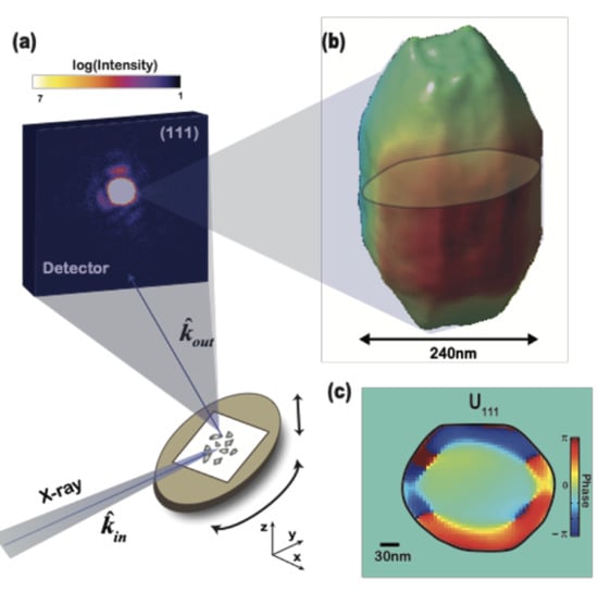
Figure 1 shows the experimental setup used to collect CXD patterns from the truncated octahedral shaped Ni nanoparticle. The asymmetrical nature of the CXD pattern namely: a lack of inversion symmetry and a broadened peak is indicative of strain inhomogeneity within the nanoparticle. This usually manifests itself as a non-zero imaginary component of the effective Bragg electron density. Iterative phase retrieval algorithms [34] were utilized to invert the CXD data to obtain the resulting complex Bragg electronic density images. The atomic displacement field scales linearly with the reconstructed phase of the complex Bragg electron density while the isosurface of the amplitude can be used to display the nanoparticle shape.
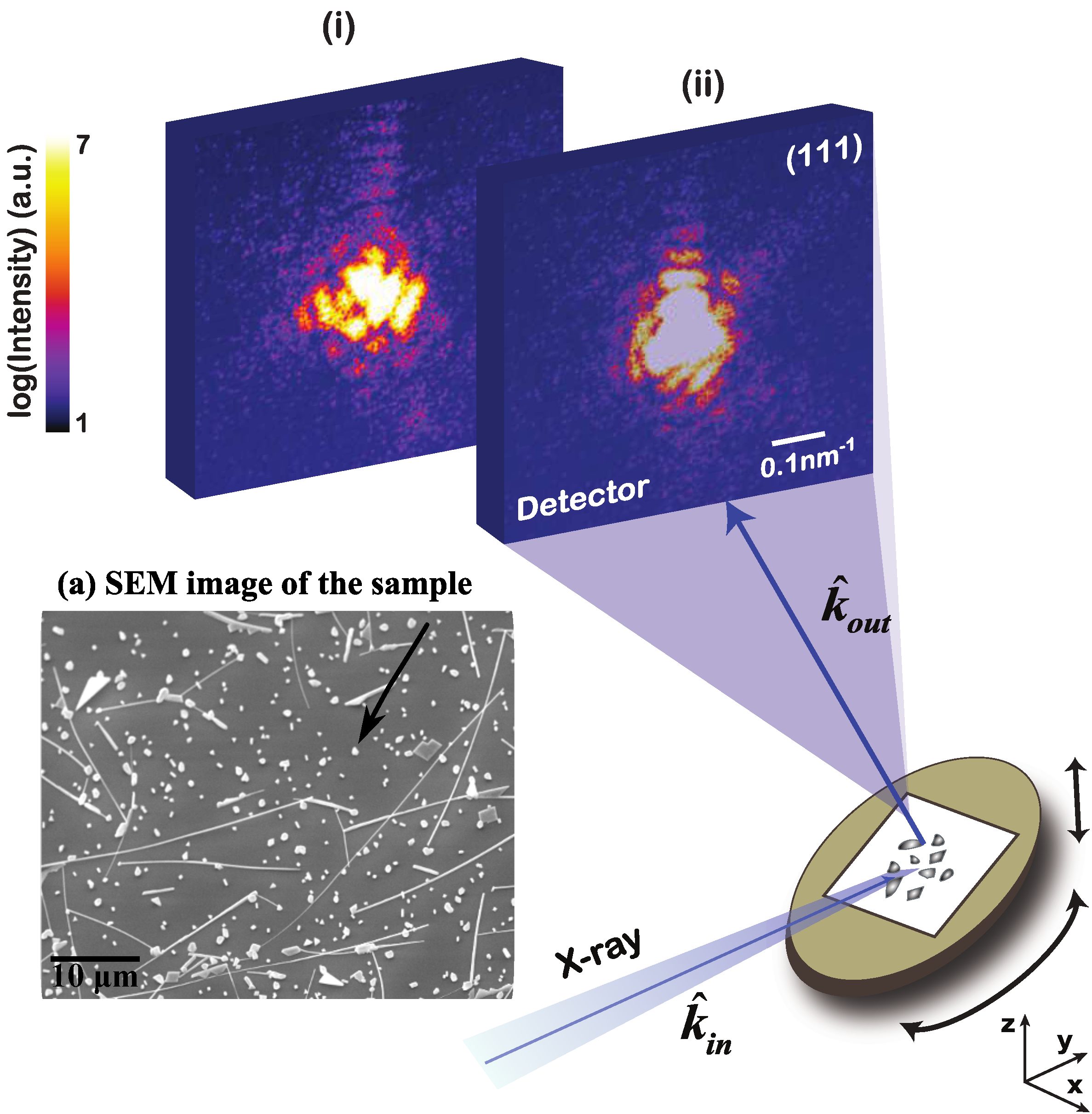
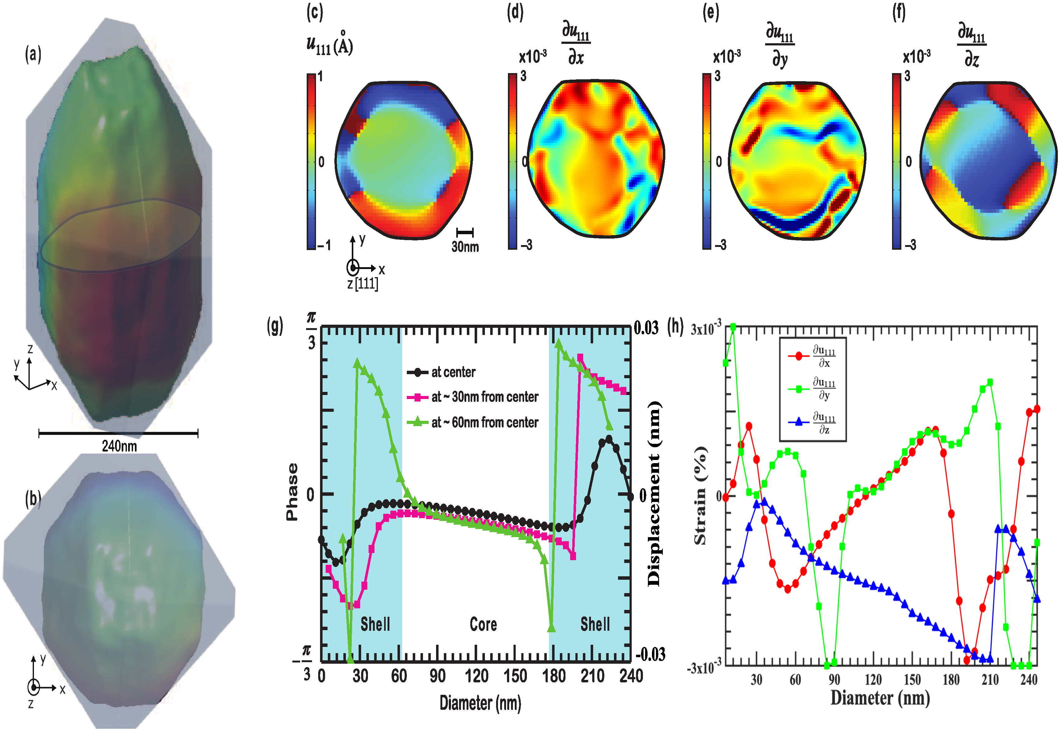
Figure 2a,b show the side and top view of the 3D isosurface of the reconstructed amplitude of the complex density depicting the shape morphology of a truncated octahedra confirmed by SEM. The support used for the reconstruction is depicted as transparent box. The reconstructed NP has a diameter of 240 nm, consistent with SEM measurements. The real-space phase , used to color the density isosurface shown in Figure 2a,b, indicates the presence of some residual strains. The magnitude of the phase within the nanoparticle varies between , corresponding to the displacement of which is approximately a third of the lattice spacing of Ni [61].
A slice cut through the reconstructed 3D displacement field of the NP shows a “core and shell” region (see Figure 2c). The core region is about 120 nm wide and has no visible dislocation features. The core region has a predominant compressive displacement field. We observe an average of compressive displacement of 0.01 nm in the core along the (111) direction. This value represents less than a 10% deviation from equilibrium Ni lattice implying the core is pure single crystal. We observe dislocations (quantifiable as phase jumps) in the shell region and at the boundary between the core and shell. According to the theory of dislocations [62], the propagations of stresses, strains and displacement fields near a dislocation source can be used to identify the dislocation type. To determine the stresses and strains associated with a given dislocation, an equation that describes how the dislocation displaces the lattice is needed. In Figure 2d–f, strong strain inhomogeneity is found within the core of the NP in the x- and y-direction while the z-direction has a predominant compressive strain distribution. These features are attributes of edge dislocations. Generally, edge dislocations create more complicated lattice distortions than screw dislocations. However, a more rigorous study of the individual dislocation types is required which is not within the scope of this work. Earlier studies [41,53] have demonstrated how CXD from samples with dislocations can be quantitatively analyzed and used to distinguish between dislocation types. Using analytical methods similar to [41,53], we identify edge dislocations along the core–shell interface and a mixture of partial and full dislocation networks within the shell boundary.
Since dislocations are responsible for slip in crystalline solids [62,63]. The nature of these dislocations are provided by the action of Frank–Reed sources [62,64] on the slip plane. The number of defect pinning points associated with the Frank–Reed source depends on the critical resolved stress. The closer the defect pinning points/sites, the higher the critical shear stress is expected. Below, we have estimated and tabulated critical shear stress () values for dislocations (or pinning sites) observed in Figure 2c.
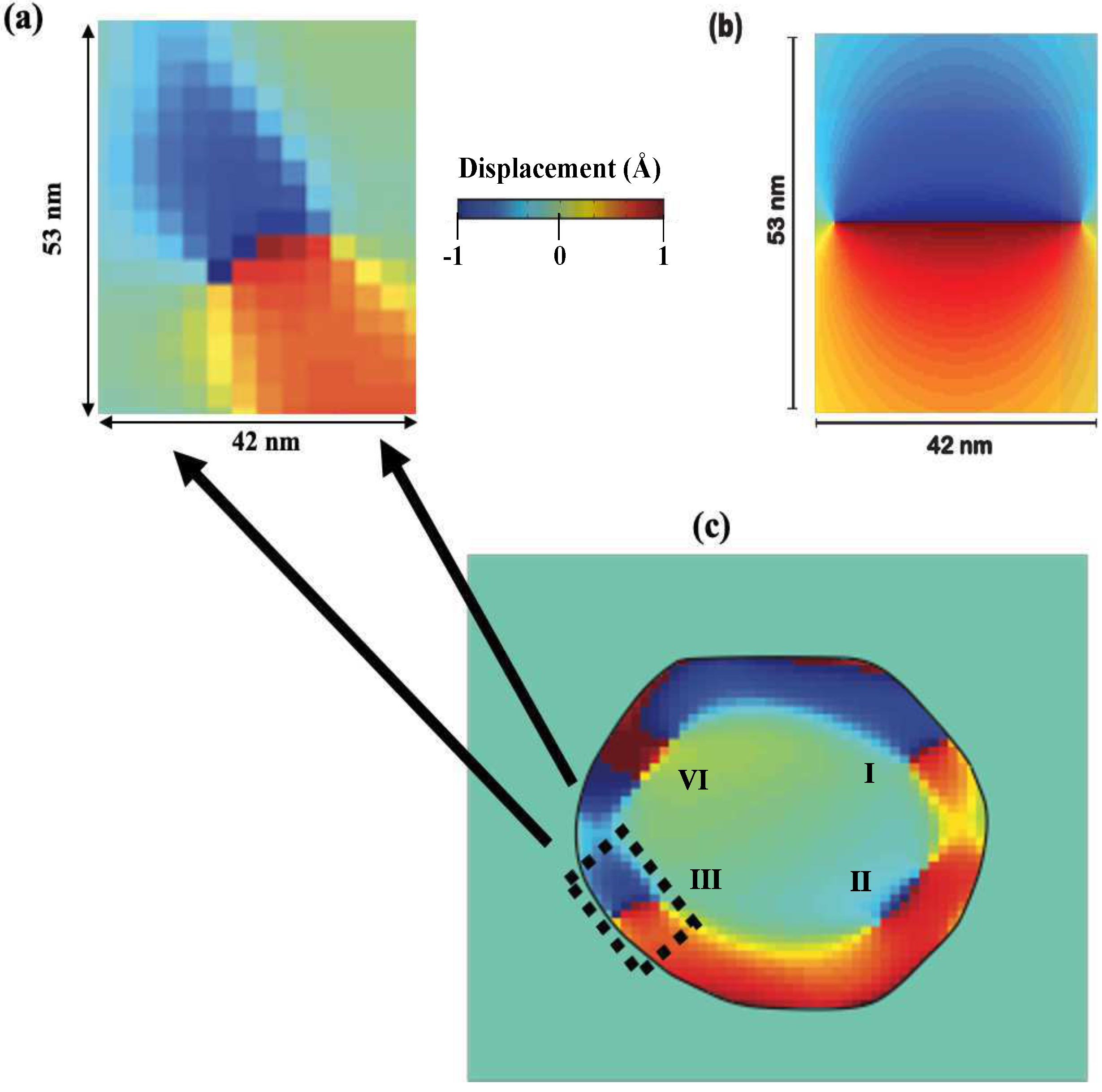
We utilize the theory of dislocations [62,64] to compare an individual dislocation obtained from BCDI (see Figure 3a) with theory (see Figure 3b), with the overall region of the reconstructed core–shell structure shown ( see Figure 3c).The observed symmetrical (and inverse radial distant from dislocation line) decay of the displacement field is consistent with the theory of elasticity. Ideally, a Frank–Reed source will cause dislocation multiplication and slip when the stress field is greater than , where D is the distance between the pinning points of the source, G is the shear modulus of the sample and is the Burgers vector of the dislocation.
Typically, in bulk [62] structures, . This provides critical stress values of the order . The calculated critical stress values for the observed dislocations in our Ni nanoparticle are summarized in Table 1. Here, we observe that the critical stress values in NPs are larger than the bulk values reported in [62]. It is thus feasible that mechanical properties and ultimately magnetic functionality of core shell systems can be altered by the presence of dislocations, the dislocation type, the behavior of the elastic displacements field near dislocations and dislocation densities. However, more rigorous study should be carried out to understand the significance of each of the parameters above and their effect on magnetic functionality such as coercivity. To understand the role played by the presence of dislocations on the equilibrium structure of the core Ni region, we utilized density functional Theory (DFT) computations within the framework of 3D periodic structure using the Vienna Ab initio Simulation Package (VASP). [65,66], and and atomistic simulations using the software package Large-scale Atomic/Molecular Massively Parallel Simulator (LAMMPS) [67]. We determined the equilibrium volume of the Ni nanoparticle by allowing the bulk lattice to change isotropically. This led to the observations of residual stress values that are less than 0.06 GPa. Further relaxation of fcc-Ni to its equilibrium structure gives an equilibrium lattice parameter that corresponds to previous experiments and theory [68,69]. In this study, the predicted strain and energy needed for changing the magnetic moments in fcc-Ni corresponds to similar strain values and displacement fields observed near the dislocations sources in Figure 3a.
The spatial resolution of our BCDI experiments is 30 nm as shown by the phase retrieval transfer function (PRTF) in Figure 4. This is a typical value for the BCDI data acquired in 34-ID-C beamline at Advanced Photon Source (APS). The PRTF allows us to analyze correlations in reconstructed phases over a number of converged solutions. The less correlated the phases are, the lower is the value of PRTF. In the analysis, the PRTF is weighted for a given spatial frequency, with conventional threshold being set at of PRTF for the frequencies that are reconstructed with reproducible phases.
To understand the correlation between structure (atomic displacement field) and functional property (magnetism), we utilize Landau-Lifshitz-Gilbert (LLG) theory [70,71,72] to model the distribution of magnetization in a core-shaped Ni nanoparticle. The distribution the of magnetization and atomic displacement field along the (111) direction in a 120 nm wide Ni nanoparticle is shown in Figure 5a,b respectively. Here we observe that the distribution of the displacement field flows with the distribution of magnetization. However, in this model, we have taken only the core of the Ni nanoparticle into consideration.
From experimental BCDI results, we have observed the presence of dislocations within the shell, and along the boundary between the core and the shell. We have also observed that such dislocation sources can strongly influence the the lattice distortions and displacement field. We propose future studies in which Ni (core) and NiO (shell) nanocrystals will be grown via controlled methods [73]. The lattice mismatch and post growth annealing conditions shall be used to control misfit dislocations between the core and the shell region. Since NiO is anti-ferromagnetic and Ni is ferromagnetic, We shall investigate dislocation pinning of magnetic domains, exchanged bias coupling and the role of core size and shell thickness using theoretical models and advanced synchrotron characterization techniques.
Numerous experimental studies [74,75] using electron microscopy have demonstrated that magnetic domain walls can be pinned by dislocations.The pinning was observed to be preferentially along the length of the dislocations, rather than being penetrated by them. Most of these studies have demonstrated that domain walls are more strongly pinned at networks of dislocations than at single dislocations. In addition, the domain walls pinned by larger dislocation sources have higher microcoercivities than those pinned at shorter dislocations. This implies the ability of dislocations to not only alter the coercivity of the magnetic system but also modify functionality such as exchanged bias. To further understand the influence of dislocations, and their associated stress field on exchanged bias, Ni-NiO core shell nanocrystals could serve as an ideal template for future studies. Using controlled growth techniques, suitable nanocrystals can be isolated for both BCDI studies and device applications. Since it is anticipated that dislocation types, the dislocation network, dislocation location, nanocrystal size, shape and faceting and interfacial mismatch-strain will play an ultimate role in the functionality of core–shell Ni-NiO systems advances in BCDI is highly relevant. Our future studies will thus involve complementary growth, volumetric characterization using BCDI and theoretical validation of interactions of dislocations in n ferromagnetic (FM) core and an antiferromagnetic (AFM) shell structure such as Ni-NiO.
Our results open up new avenues for the imaging and mapping of deformation and elastic properties in buried magnetic interfaces to help unlock the potential for a synthesis-characterization feedback loop. Future works should focus on understanding how various structural defects in the nanoparticle may influence the magnetic domain structures and the heterogeneities of magnetization.
3. Materials and Methods
3.1. Sample Growth
Ni nanostructures were grown on an amorphous SiO templated Si (100) substrates via a one-step catalyst-free thermal chemical vapor deposition method. A powdered NiCl. 6HO precursor was first dried at 200 C in a nickel boat in a quartz tube along with 5 Si (100) substrates lined up next to the boat. The temperature of the system was then raised to 650 C, and the growth was allowed to occur for 30 min. Argon flow was maintained throughout the process. Afterwards, the entire system was cooled to room temperature while maintaining the Ar flow in the closed system. Scanning electron microscopy (JEOL JSM-6332- Field Emission Scanning Electron Microscope) revealed well defined nickel nano-objects.
3.2. CXD Experiments and BCDI Data Reconstructions
Coherent X-rays of keV with 1 eV bandwidth, resulting in a longitudinal coherence length of about 0.7 m from the 34-ID-C beamline of the Advanced Photon Source (APS) were focused onto the sample using Kirkpatrick–Baez (KB) mirrors that achieved a focus around about 2 m × 2 m. The diffraction patterns in the vicinity of the (111) Bragg reflections were measured using a direct-detection charge-coupled device (CCD) (Roper/PI direct detection CCD) with 20.5 m pixels located on the detector arm, 1.05 m away from the sample. 3D CXD pattern was then acquired as a -scan, rotating in 81 steps of 0.006 degrees about a vertical axis. The CXD patterns were inverted to images with a 3D Fourier transform and coordinate transformation, following support-based phasing using a version of Fienup’s hybrid input-output algorithm. The iterative reconstructions were performed with 30 iteration of error reduction (ER), 300 iterations of hybrid input-output (HIO) followed by 30 iterations of ER with a random amplitude and a flat phase for the initial starting guesses.
To ensure and confirm the reproducibility and uniqueness of the reconstructed complex Bragg electronic density, we performed a series of phase retrieval procedures with different random input phases for the measured scattered radiation. We define a measure for the error in the BCDI reconstruction in the following form:
where is the magnitude of the reconstructed amplitude and is the experimental intensity in the reciprocal space. An estimate of the resolution of our BCDI reconstruction is obtained using the phase retrieval transfer function (PRTF) [76,77]. The spatial resolution of the reconstructed results is estimated to be around 30 nm as given by the PRTF shown in Figure 4.
3.3. Classical Potential Simulations
In order to confirm the equilibrium shape of the nanoparticle, we utilize atomistic MEAM [78] and EAM [79] calculations. All computations were performed with the software package Large-scale Atomic/Molecular Massively Parallel Simulator (LAMMPS) [67]. We constructed a 9 shell Mackay cluster [80,81,82] containing 2057 atoms. The cluster was placed in a periodic box and surrounded by vacuum that was sufficiently large to eliminate interactions between modeled cluster and its periodic images. Subsequently the ground state structure of the cluster was determined by relaxing the cluster using a conjugate gradient algorithm as implemented in LAMMPS. density-functional-theory (DFT) computations within the framework of 3D periodic structure computations using VASP [65,66]. Interactions between nuclei and electrons were described within the all-electron like the projector augmented-wave (PAW)-formalism [68,83]. The valence electron configuration was . Electronic exchange and correlation effects were treated within the Generalized-Gradient-Approximation (GGA) as parameterized by Perdew–Burke–Ernzerhof. All computations were performed for the conventional unit cell fcc-Ni containing four Ni atoms using a plane-wave energy-cutoff of 500 eV and a -centered 16 × 16 × 16 k-point gird. The Fermi-level was slightly smeared using a Fermi–Dirac distribution function with a width of 0.026 eV. These computational settings lead to total energies that are converged to better than 1 meV/atom. The equilibrium volume was determined by allowing the lattice to change isotropically. Residual stresses are less than 0.06 GPa. Structural relaxation of fcc-Ni to its equilibrium structure gives an equilibrium lattice parameter that corresponds to previous experiments and theory [68,69]. The predicted strain and energy needed for changing the magnetic moments in fcc-Ni corresponds to those obtained experimentally.
3.4. Landau–Lifshitz–Gilbert (LLG) Simulation
The free energy of the nickel particle is F is described as , where is the exchange, denotes the anisotropy energy, is the dipole–dipole interaction energy and is the elastic energy. The exchange energy density in micromagnetism is written as , where A is the exchange coefficient, and (i = 1, 2, 3) are components of the unit magnetization vector. The anisotropy energy density of a cubic magnetic crystal is given by , where and are anisotropy constants. The dipole–dipole energy is given by Where is the permeability of the vacuum, is the demagnetization field and is the saturation magnetization. The elastic energy is written as , where is the elastic constant, is the elastic strain and is the spontaneous strain which is given by .
The temporal evolution of the magnetization is described by the Landau–Lifshitz–Gilbert (LLG) equation . Here, , is the gyromagnetic ratio, is the damping constant and is the effective magnetic field . For the nickel particle, the parameters we use in the simulation are × Jm, × Jm, , , A/m. The elastic constants are N/m, N/m and N/m.
Author Contributions
E.F. (Edwin Fohtung), R.H., E.F. (Eric Fullerton) and O.S. planned and organized the experiments. E.F. (Edwin Fohtung) and R.H. performed the experiments. The data was analyzed by E.F. (Edwin Fohtung) and X.S. The Ni nanowires were manufactured and synthesized by E.F. (Eric Fullerton). DFT computations were performed by B.K. Landau–Lifshitz–Gilbert (LLG) simulations were performed by Z.L., E.F. (Edwin Fohtung), X.S., E.F. (Eric Fullerton) and O.S. wrote the manuscript, with input from all co-authors. Correspondence and requests for materials should be addressed to E.F. (Edwin Fohtung). All authors have read and agree to the published version of the manuscript.
Funding
This work was supported by the US Department of Defense, Air Force Office of Scientific Research under Award No. FA9550-14-1-0363 (Program Manager: Ali Sayir). This research used resources of the Advanced Photon Source (APS), a U.S. Department of Energy (DOE) Office of Science User Facility operated for the DOE Office of Science by Argonne National Laboratory (ANL) under contract No. DE-AC02-06CH11357.
Acknowledgments
The Bragg coherent Diffraction Experiments were carried out at the Advanced photon source. Raw data was measured at the Advanced Photon Source Sector 34-ID-C and are permanently deposited there. The data supporting the findings of this study are available from the corresponding author upon request. We thank the staff at ANL and the APS for their support. We also acknowledge earlier discussions with Erandi Wijerthna at New Mexico State University.
Conflicts of Interest
The authors declare no financial conflict of interest.
Abbreviations
| BCDI | Bragg coherent X-ray diffractive imaging |
| CXD | Coherent X-ray diffraction |
| SEM | Scanning electron microscopy |
| XRD | X-ray diffraction |
| NP | Nanoparticle |
| EF-TEM | Energy-filtered transmission electron microscopy |
| HR-TEM | High-resolution transmission electron microscopy |
| PRTF | Phase retrieval transfer function |
References
- Golosovsky, I.; Salazar-Alvarez, G.; López-Ortega, A.; González, M.; Sort, J.; Estrader, M.; Surinach, S.; Baró, M.; Nogués, J. Magnetic proximity effect features in antiferromagnetic/ferrimagnetic core-shell nanoparticles. Phys. Rev. Lett. 2009, 102, 247201. [Google Scholar] [CrossRef] [Green Version]
- Zeng, H.; Li, J.; Wang, Z.; Liu, J.; Sun, S. Bimagnetic core/shell FePt/Fe3O4 nanoparticles. Nano Lett. 2004, 4, 187–190. [Google Scholar] [CrossRef]
- Estrader, M.; López-Ortega, A.; Estradé, S.; Golosovsky, I.; Salazar-Alvarez, G.; Vasilakaki, M.; Trohidou, K.; Varela, M.; Stanley, D.; Sinko, M.; et al. Robust antiferromagnetic coupling in hard-soft bi-magnetic core/shell nanoparticles. Nat. Commun. 2013, 4, 2960. [Google Scholar] [CrossRef] [PubMed]
- Dormann, J.; Fiorani, D. Magnetic Properties of Fine Particles; Elsevier: Amsterdam, The Netherlands, 2012. [Google Scholar]
- Winkler, E.; Zysler, R.; Mansilla, M.V.; Fiorani, D. Surface anisotropy effects in NiO nanoparticles. Phys. Rev. B 2005, 72, 132409. [Google Scholar] [CrossRef]
- Leslie-Pelecky, D.; Rieke, R. Magnetic properties of nanostructured materials. Chem. Mater. 1996, 8, 1770–1783. [Google Scholar] [CrossRef]
- Manna, P.; Yusuf, S.; Basu, M.; Pal, T. The magnetic proximity effect in a ferrimagnetic Fe3O4 core/ferrimagnetic γ-Mn2O3 shell nanoparticle system. J. Phys. Condens. Matter 2011, 23, 506004. [Google Scholar] [CrossRef]
- Hu, Y.; Wu, G.Z.; Liu, Y.; Du, A. Field-induced transitions from negative to positive exchange bias in nanoparticles with inverted ferromagnetic-antiferromagnetic core-shell morphology. J. Appl. Phys. 2012, 111, 053904. [Google Scholar] [CrossRef]
- Nogués, J.; Sort, J.; Langlais, V.; Skumryev, V.; Surinach, S.; Munoz, J.; Baró, M. Exchange bias in nanostructures. Phys. Rep. 2005, 422, 65–117. [Google Scholar] [CrossRef]
- Skumryev, V.; Stoyanov, S.; Zhang, Y.; Hadjipanayis, G.; Givord, D.; Nogues, J. Beating the superparamagnetic limit with exchange bias. Nature 2003, 423, 850–853. [Google Scholar] [CrossRef]
- Schuller, I.K.; Kim, S.; Leighton, C. Magnetic superlattices and multilayers. J. Magn. Magn. Mater. 1999, 200, 571–582. [Google Scholar] [CrossRef]
- Nogués, J.; Lederman, D.; Moran, T.; Schuller, I.K. Positive Exchange Bias in Fe F 2-Fe Bilayers. Phys. Rev. Lett. 1996, 76, 4624. [Google Scholar] [CrossRef] [PubMed] [Green Version]
- Moser, A.; Berger, A.; Margulies, D.T.; Fullerton, E.E. Magnetic tuning of biquadratic exchange coupling in magnetic thin films. Phys. Rev. Lett. 2003, 91, 097203. [Google Scholar] [CrossRef] [PubMed]
- Granitzer, P.; Rumpf, K.; Krenn, H. Ferromagnetic nanostructures incorporated in quasi-one-dimensional porous silicon channels suitable for magnetic sensor applications. J. Nanomater. 2006, 2006, 18125. [Google Scholar] [CrossRef] [Green Version]
- Garcia-Sanchez, F.; Szambolics, H.; Mihai, A.; Vila, L.; Marty, A.; Attané, J.P.; Toussaint, J.C.; Buda-Prejbeanu, L. Effect of crystalline defects on domain wall motion under field and current in nanowires with perpendicular magnetization. Phys. Rev. B 2010, 81, 134408. [Google Scholar] [CrossRef]
- Singh, M.K.; Agarwal, A.; Swarnkar, R.K.; Gopal, R.; Kotnala, R. Magnetic Properties of Ni/NiO Core–Shell Nanoparticles Synthesized by Nanosecond Laser Irradiance of Water Suspended Ni Particles. Sci. Adv. Mater. 2012, 4, 532–536. [Google Scholar] [CrossRef]
- Jayakumar, O.; Tyagi, A. Synthesis and characterisation of dispersible Ni@ NiO core shell magnetic nanoparticles by polyol method. Int. J. Nanotechnol. 2010, 7, 852–860. [Google Scholar] [CrossRef]
- D’Addato, S.; Grillo, V.; Altieri, S.; Frabboni, S.; Valeri, S. Assembly and structure of Ni/NiO core-shell nanoparticles. Appl. Surf. Sci. 2012, 260, 13–16. [Google Scholar] [CrossRef]
- Yuan, C.; Zhang, Q.; Luo, X.; Zhang, Z. Formation and strain distribution of Ni/NiO core/shell magnetic nanoparticles fabricated by pulsed laser deposition. Sci. China Phys. Mechan. Astron. 2011, 54, 1254–1257. [Google Scholar] [CrossRef]
- Chen, B.; Lutker, K.; Raju, S.V.; Yan, J.; Kanitpanyacharoen, W.; Lei, J.; Yang, S.; Wenk, H.R.; Mao, H.K.; Williams, Q. Texture of nanocrystalline nickel: Probing the lower size limit of dislocation activity. Science 2012, 338, 1448–1451. [Google Scholar] [CrossRef]
- Patel, J.; Authier, A. X- ray topography of defects produced after heat treatment of dislocation- free silicon containing oxygen. J. Appl. Phys. 1975, 46, 118–125. [Google Scholar] [CrossRef]
- Hÿtch, M.J.; Putaux, J.L.; Pénisson, J.M. Measurement of the displacement field of dislocations to 0.03 Å by electron microscopy. Nature 2003, 423, 270–273. [Google Scholar] [CrossRef] [PubMed]
- Bilderback, D.H.; Elleaume, P.; Weckert, E. Review of third and next generation synchrotron light sources. J. Phys. B At. Mol. Opt. Phys. 2005, 38, S773. [Google Scholar] [CrossRef]
- Fohtung, E.; Kim, J.W.; Chan, K.T.; Harder, R.; Fullerton, E.E.; Shpyrko, O.G. Probing the three-dimensional strain inhomogeneity and equilibrium elastic properties of single crystal Ni nanowires. Appl. Phys. Lett. 2012, 101, 033107. [Google Scholar] [CrossRef] [Green Version]
- Watari, M.; McKendry, R.A.; Vögtli, M.; Aeppli, G.; Soh, Y.A.; Shi, X.; Xiong, G.; Huang, X.; Harder, R.; Robinson, I.K. Differential stress induced by thiol adsorption on facetted nanocrystals. Nat. Mater. 2011, 10, 862–866. [Google Scholar] [CrossRef] [Green Version]
- Harder, R.; Liang, M.; Sun, Y.; Xia, Y.; Robinson, I. Imaging of complex density in silver nanocubes by coherent x-ray diffraction. New J. Phys. 2010, 12, 035019. [Google Scholar] [CrossRef]
- Robinson, I.; Harder, R. Coherent X-ray diffraction imaging of strain at the nanoscale. Nat. Mater. 2009, 8, 291–298. [Google Scholar] [CrossRef]
- Minkevich, A.; Fohtung, E.; Slobodskyy, T.; Riotte, M.; Grigoriev, D.; Schmidbauer, M.; Irvine, A.; Novák, V.; Holỳ, V.; Baumbach, T. Selective coherent x-ray diffractive imaging of displacement fields in (Ga, Mn) As/GaAs periodic wires. Phys. Rev. B 2011, 84, 054113. [Google Scholar] [CrossRef] [Green Version]
- Harder, R.; Robinson, I.K. Coherent X-Ray Diffraction Imaging of Morphology and Strain in Nanomaterials. JOM 2013, 65, 1202–1207. [Google Scholar] [CrossRef] [Green Version]
- Clark, J.; Beitra, L.; Xiong, G.; Higginbotham, A.; Fritz, D.; Lemke, H.; Zhu, D.; Chollet, M.; Williams, G.; Messerschmidt, M.; et al. Ultrafast Three-Dimensional Imaging of Lattice Dynamics in Individual Gold Nanocrystals. Science 2013, 341, 56–59. [Google Scholar] [CrossRef] [Green Version]
- Chapman, H.N.; Barty, A.; Bogan, M.J.; Boutet, S.; Frank, M.; Hau-Riege, S.P.; Marchesini, S.; Woods, B.W.; Bajt, S.; Benner, W.H.; et al. Femtosecond diffractive imaging with a soft-X-ray free-electron laser. Nat. Phys. 2006, 2, 839–843. [Google Scholar] [CrossRef] [Green Version]
- Pateras, A.; Harder, R.; Cha, W.; Gigax, J.G.; Baldwin, J.K.; Tischler, J.; Xu, R.; Liu, W.; Erdmann, M.J.; Kalt, R.; et al. Combining Laue diffraction with Bragg coherent diffraction imaging at 34-ID-C. arXiv 2020, arXiv:2002.11859. [Google Scholar]
- Li, L.; Xie, Y.; Maxey, E.; Harder, R. Methods for operando coherent X-ray diffraction of battery materials at the Advanced Photon Source. J. Synchrotron Radiat. 2019, 26, 220–229. [Google Scholar] [CrossRef] [PubMed]
- Fienup, J.R. Phase retrieval algorithms: A comparison. Appl. Opt. 1982, 21, 2758–2769. [Google Scholar] [CrossRef] [PubMed] [Green Version]
- Fienup, J.R. Phase retrieval algorithms: A personal tour. Appl. Opt. 2013, 52, 45–56. [Google Scholar] [CrossRef] [PubMed] [Green Version]
- Guo, C.; Liu, S.; Sheridan, J.T. Iterative phase retrieval algorithms. I: Optimization. Appl. Opt. 2015, 54, 4698–4708. [Google Scholar] [CrossRef] [Green Version]
- Minkevich, A.; Baumbach, T.; Gailhanou, M.; Thomas, O. Applicability of an iterative inversion algorithm to the diffraction patterns from inhomogeneously strained crystals. Phys. Rev. B 2008, 78, 174110. [Google Scholar] [CrossRef]
- Karpov, D.; Liu, Z.; dos Santos Rolo, T.; Harder, R.; Balachandran, P.; Xue, D.; Lookman, T.; Fohtung, E. Three-dimensional imaging of vortex structure in a ferroelectric nanoparticle driven by an electric field. Nat. Commun. 2017, 8, 1–8. [Google Scholar] [CrossRef]
- Liu, Z.; Schold, E.; Karpov, D.; Harder, R.; Lookman, T.; Fohtung, E. Needle-Like Ferroelastic Domains in Individual Ferroelectric Nanoparticles. Adv. Electron. Mater. 2020, 6, 1901300. [Google Scholar] [CrossRef]
- Pateras, A.; Harder, R.; Manna, S.; Kiefer, B.; Sandberg, R.L.; Trugman, S.; Kim, J.W.; de la Venta, J.; Fullerton, E.E.; Shpyrko, O.G.; et al. Room temperature giant magnetostriction in single-crystal nickel nanowires. NPG Asia Mater. 2019, 11, 1–7. [Google Scholar] [CrossRef]
- Ulvestad, A.; Nashed, Y.; Beutier, G.; Verdier, M.; Hruszkewycz, S.; Dupraz, M. Identifying defects with guided algorithms in bragg coherent diffractive imaging. Sci. Rep. 2017, 7, 1–9. [Google Scholar] [CrossRef] [Green Version]
- Karpov, D.; Liu, Z.; Kumar, A.; Kiefer, B.; Harder, R.; Lookman, T.; Fohtung, E. Nanoscale topological defects and improper ferroelectric domains in multiferroic barium hexaferrite nanocrystals. Phys. Rev. B 2019, 100, 054432. [Google Scholar] [CrossRef] [Green Version]
- Kawaguchi, T.; Keller, T.F.; Runge, H.; Gelisio, L.; Seitz, C.; Kim, Y.Y.; Maxey, E.R.; Cha, W.; Ulvestad, A.; Hruszkewycz, S.O.; et al. Gas-Induced Segregation in Pt-Rh Alloy Nanoparticles Observed by In Situ Bragg Coherent Diffraction Imaging. Phys. Rev. Lett. 2019, 123, 246001. [Google Scholar] [CrossRef]
- Robinson, I.; Assefa, T.A.; Cao, Y.; Gu, G.; Harder, R.; Maxey, E.; Dean, M.P. Domain texture of the orthorhombic phase of La2−xBaxCuO4. J. Supercond. Nov. Magn. 2020, 33, 99–106. [Google Scholar] [CrossRef] [Green Version]
- Ulvestad, A.; Cherukara, M.; Harder, R.; Cha, W.; Robinson, I.; Soog, S.; Nelson, S.; Zhu, D.; Stephenson, G.; Heinonen, O.; et al. Bragg coherent diffractive imaging of zinc oxide acoustic phonons at picosecond timescales. Sci. Rep. 2017, 7, 1–8. [Google Scholar] [CrossRef] [PubMed] [Green Version]
- Hofmann, F.; Tarleton, E.; Harder, R.J.; Phillips, N.W.; Ma, P.W.; Clark, J.N.; Robinson, I.K.; Abbey, B.; Liu, W.; Beck, C.E. 3D lattice distortions and defect structures in ion-implanted nano-crystals. Sci. Rep. 2017, 7, 45993. [Google Scholar] [CrossRef] [PubMed] [Green Version]
- Phillips, N.; Yu, H.; Das, S.; Yang, D.; Mizohata, K.; Liu, W.; Xu, R.; Harder, R.; Hofmann, F. Nanoscale Lattice Strains in Self-ion-implanted Tungsten. Acta Mater. 2020, 195, 219–228. [Google Scholar] [CrossRef]
- Singer, A.; Zhang, M.; Hy, S.; Cela, D.; Fang, C.; Wynn, T.; Qiu, B.; Xia, Y.; Liu, Z.; Ulvestad, A.; et al. Nucleation of dislocations and their dynamics in layered oxide cathode materials during battery charging. Nat. Energy 2018, 3, 641–647. [Google Scholar] [CrossRef]
- Karpov, D.; Fohtung, E. Bragg coherent diffractive imaging of strain at the nanoscale. J. Appl. Phys. 2019, 125, 121101. [Google Scholar] [CrossRef] [Green Version]
- Quiney, H.; Williams, G.; Fohtung, E. Editorial for special issue on coherent diffractive imaging. J. Opt. 2017, 20, 010201. [Google Scholar] [CrossRef] [Green Version]
- Yau, A.; Cha, W.; Kanan, M.W.; Stephenson, G.B.; Ulvestad, A. Bragg coherent diffractive imaging of single-grain defect dynamics in polycrystalline films. Science 2017, 356, 739–742. [Google Scholar] [CrossRef] [Green Version]
- Newton, M.C.; Shi, X.; Wagner, U.; Rau, C. Coherent diffraction imaging of a progressively deformed nanocrystal. Phys. Rev. Mater. 2019, 3, 043803. [Google Scholar] [CrossRef] [Green Version]
- Ulvestad, A.; Singer, A.; Clark, J.N.; Cho, H.M.; Kim, J.W.; Harder, R.; Maser, J.; Meng, Y.S.; Shpyrko, O.G. Topological defect dynamics in operando battery nanoparticles. Science 2015, 356, 1344–1347. [Google Scholar] [CrossRef] [PubMed] [Green Version]
- Xiong, G.; Moutanabbir, O.; Reiche, M.; Harder, R.; Robinson, I. Coherent X-ray Diffraction Imaging and Characterization of Strain in Silicon-on-Insulator Nanostructures. Adv. Mater. 2014, 26, 7747–7763. [Google Scholar] [CrossRef] [Green Version]
- Cherukara, M.J.; Pokharel, R.; O’Leary, T.S.; Baldwin, J.K.; Maxey, E.; Cha, W.; Maser, J.; Harder, R.J.; Fensin, S.J.; Sandberg, R.L. Three-dimensional X-ray diffraction imaging of dislocations in polycrystalline metals under tensile loading. Nat. Commun. 2018, 9, 1–6. [Google Scholar] [CrossRef] [PubMed]
- Hofmann, F.; Phillips, N.W.; Das, S.; Karamched, P.; Hughes, G.M.; Douglas, J.O.; Cha, W.; Liu, W. Nanoscale imaging of the full strain tensor of specific dislocations extracted from a bulk sample. Phys. Rev. Mater. 2020, 4, 013801. [Google Scholar] [CrossRef] [Green Version]
- Chan, K.T.; Kan, J.J.; Doran, C.; Ouyang, L.; Smith, D.J.; Fullerton, E.E. Oriented growth of single-crystal Ni nanowires onto amorphous SiO2. Nano Lett. 2010, 10, 5070–5075. [Google Scholar] [CrossRef]
- Chan, K.T.; Kan, J.J.; Doran, C.; Ouyang, L.; Smith, D.J.; Fullerton, E.E. Controlled growth behavior of chemical vapor deposited Ni nanostructures. Philos. Mag. 2012, 92, 2173–2186. [Google Scholar] [CrossRef]
- Pfeifer, M.; Williams, G.; Vartanyants, I.; Harder, R.; Robinson, I. Three-dimensional mapping of a deformation field inside a nanocrystal. Nature 2006, 442, 63–66. [Google Scholar] [CrossRef]
- Manna, S.; Kim, J.W.; Lubarda, M.V.; Wingert, J.; Harder, R.; Spada, F.; Lomakin, V.; Shpyrko, O.; Fullerton, E.E. Characterization of strain and its effects on ferromagnetic nickel nanocubes. AIP Adv. 2017, 7, 125025. [Google Scholar] [CrossRef] [Green Version]
- Miao, J.; Sayre, D.; Chapman, H. Phase retrieval from the magnitude of the Fourier transforms of nonperiodic objects. JOSA A 1998, 15, 1662–1669. [Google Scholar] [CrossRef]
- Callister, W.D.; Rethwisch, D.G. Materials Science and Engineering; John Wiley & Sons: New York, NY, USA, 2011; Volume 5. [Google Scholar]
- Landau, L.; Lifshitz, E.; Sykes, J.; Reid, W.; Dill, E. Theory of Elasticity: Volume 7 of Course of Theoretical Physics. Phys. Today 1960, 13, 44. [Google Scholar] [CrossRef]
- Frank, F.; Read, W., Jr. Multiplication processes for slow moving dislocations. Phys. Rev. 1950, 79, 722. [Google Scholar] [CrossRef]
- Kresse, G.; Hafner, J. Ab initio molecular dynamics for open-shell transition metals. Phys. Rev. B 1993, 48, 13115. [Google Scholar] [CrossRef]
- Kresse, G.; Furthmüller, J. Efficient iterative schemes for ab initio total-energy calculations using a plane-wave basis set. Phys. Rev. B 1996, 54, 11169. [Google Scholar] [CrossRef]
- Prieve, D.C.; Russel, W.B. Simplified predictions of Hamaker constants from Lifshitz theory. J. Colloid Interface Sci. 1988, 125, 1–13. [Google Scholar] [CrossRef]
- Kresse, G.; Joubert, D. From ultrasoft pseudopotentials to the projector augmented-wave method. Phys. Rev. B 1999, 59, 1758. [Google Scholar] [CrossRef]
- Wyckoff, R.W.G. Crystal Structures; Interscience Publishers: New York, NY, USA, 1963; Volume 1. [Google Scholar]
- Skrotskii, G.V. The landau-lifshitz equation revisited. Uspekhi Fiz. Nauk 1984, 144, 681. [Google Scholar] [CrossRef]
- Lakshmanan, M. The fascinating world of the Landau–Lifshitz–Gilbert equation: An overview. Philos. Trans. R. Soc. A Math. Phys. Eng. Sci. 2011, 369, 1280–1300. [Google Scholar] [CrossRef] [PubMed]
- Aharoni, A. Introduction to the Theory of Ferromagnetism; Clarendon Press: Oxford, UK, 2000; Volume 109. [Google Scholar]
- D’Addato, S.; Spadaro, M.C.; Luches, P.; Grillo, V.; Frabboni, S.; Valeri, S.; Ferretti, A.; Capetti, E.; Ponti, A. Controlled growth of Ni/NiO core–shell nanoparticles: Structure, morphology and tuning of magnetic properties. Appl. Surf. Sci. 2014, 306, 2–6. [Google Scholar] [CrossRef]
- Lindquist, A.; Feinberg, J.M.; Harrison, R.; Loudon, J.; Newell, A. Domain wall pinning and dislocations: Investigating magnetite deformed under conditions analogous to nature using transmission electron microscopy. J. Geophys. Res. Solid Earth 2015, 120, 1415–1430. [Google Scholar] [CrossRef] [Green Version]
- Fidler, J.; Kirchmayer, H.; Skalicky, P. Pinning of magnetic domain walls at dislocations and precipitates in Co5Sm crystals. Philos. Mag. B 1981, 43, 765–780. [Google Scholar] [CrossRef]
- Chapman, H.N.; Barty, A.; Marchesini, S.; Noy, A.; Hau-Riege, S.P.; Cui, C.; Howells, M.R.; Rosen, R.; He, H.; Spence, J.C.; et al. High-resolution ab initio three-dimensional x-ray diffraction microscopy. JOSA A 2006, 23, 1179–1200. [Google Scholar] [CrossRef] [PubMed]
- Marchesini, S.; Chapman, H.; Barty, A.; Cui, C.; Howells, M.; Spence, J.; Weierstall, U.; Minor, A. Phase aberrations in diffraction microscopy. arXiv 2005, arXiv:0510033. [Google Scholar]
- Baskes, M. Probing the structure of iron at extreme conditions by X-ray absorption near-edge structure calculations. Phys. Rev. B 1992, 46, 2727–2742. [Google Scholar] [CrossRef]
- Zhou, X.; Johnson, R.; Wadley, H. Misfit-energy-increasing dislocations in vapor-deposited CoFe/NiFe multilayers. Phys. Rev. B 2004, 69, 144113. [Google Scholar] [CrossRef] [Green Version]
- Mackay, A.L. A dense non-crystallographic packing of equal spheres. Acta Crystallogr. 1962, 15, 916–918. [Google Scholar] [CrossRef]
- Baletto, F.; Ferrando, R.; Fortunelli, A.; Montalenti, F.; Mottet, C. Crossover among structural motifs in transition and noble-metal clusters. J. Chem. Phys. 2002, 116, 3856. [Google Scholar] [CrossRef]
- Cleveland, C.; Landman, U.; Schaaff, T.; Sha, M. gullin, PW Stephens and RL Whetten. Phys. Rev. Lett. 1997, 79, 1873–1876. [Google Scholar] [CrossRef]
- Blöchl, P.E. Projector augmented-wave method. Phys. Rev. B 1994, 50, 17953. [Google Scholar] [CrossRef] [Green Version]
Figure 1.
Schematic of the experimental set-up and sample. (a) Scanning electron microscopy (SEM) image showing a single isolated Ni nanoparticle (identified by the arrow) in an ensemble of Ni nano-objects. A monochromatic X-ray beam of wave vector focused by Kirkpatrick–Baez (KB) mirrors (not shown is sketch impinges on the sample. By rotating the sample through the Bragg condition in increments of about 0.006 degrees, coherent X-ray diffraction (CXD) patterns in the vicinity of the (111) reciprocal lattice point are recorded with a two-dimensional pixelated detector. Two typical diffraction patterns (out of the hundreds of patterns collected) are shown here in (i,ii)).

Figure 2.
Reconstructed projections of the displacement and strain. (a,b) 3D isosurface projections of the displacement field and shape morphology of the nanoparticle. (c–f) 2D projections that are extracted from the central slices of the reconstructions, showing strain inhomogeneity of the core and heterogeneity within the shell of the nanoparticle. The strain in (c–f) with non-uniform structure without symmetry within the core; while the strain within the shell is diverse when comparing the components in the three orthogonal directions as shown in (d–h). Line plots showing smooth variation and inhomogeneous strain within the core layer of the nanoparticle (Ni) and large phase jumps in the NiO shell region depicting the presence of singularities such as defects and dislocations. In (g), the phase is plotted from the central slices of the 3D reconstructed particle, 30 nm and 60 nm away from the central slices of the 3D particle, respectively. In (h), the plot was extracted from the one end of the particle to the other end of the particle, that is, from the shell–core–shell for the entire particle for the central slice linecut.

Figure 3.
Edge dislocation result and simulation. (a) Reconstructed stress field in the vicinity of an edge dislocation within the nanoparticle shell region (magnified 3X) is compared with simulated stress (b) Stress due to an edge dislocation. (c) The overall region of the reconstructed core–shell structure.

Figure 4.
Resolution estimation by phase retrieval transfer function (PRTF). The phase retrieval transfer function is a tool that provides an accurate resolution measure. It takes a value of 1 where the iterative algorithm produced perfect convergence consistently, and a value near 0 where the algorithm continually failed to converge. Dashed line on the graph shows 50% cutoff frequency which is used to estimate the threshold of resolution reliability, which for our Bragg coherent diffraction imaging (BCDI) experiment is approximately 30 nm in Figure 2 and Figure 3.

Figure 5.
(a) The simulated distribution of magnetization within a single Ni nanoparticle. The arrows represent the distribution of the magnetization, and the color denotes the magnitude of the component . (b) The distribution of the displacement along (001) axis.
Figure 5.
(a) The simulated distribution of magnetization within a single Ni nanoparticle. The arrows represent the distribution of the magnetization, and the color denotes the magnitude of the component . (b) The distribution of the displacement along (001) axis.


Table 1.
The calculated values for each dislocation.
| Dislocation | Dislocation | Source Size | Critical Shear | Stacking Fault | |
|---|---|---|---|---|---|
| ( 0.22 nm) | Type | Stress | Energy | ||
| (i) | 28b | full | 43 nm | = 12.32 GPa | - |
| (ii) | 28b | full | 43 nm | = 12.32 GPa | - |
| (iii) | 27b | full | 42 nm | = 12.16 GPa | - |
| (iv) | 19b | partial | 30 nm | = 11.98 GPa | 1421 mJ/m |
© 2020 by the authors. Licensee MDPI, Basel, Switzerland. This article is an open access article distributed under the terms and conditions of the Creative Commons Attribution (CC BY) license (http://creativecommons.org/licenses/by/4.0/).
Share and Cite
MDPI and ACS Style
Shi, X.; Harder, R.; Liu, Z.; Shpyrko, O.; Fullerton, E.; Kiefer, B.; Fohtung, E. Nanoscale Mapping of Heterogeneous Strain and Defects in Individual Magnetic Nanocrystals. Crystals 2020, 10, 658. https://doi.org/10.3390/cryst10080658
AMA Style
Shi X, Harder R, Liu Z, Shpyrko O, Fullerton E, Kiefer B, Fohtung E. Nanoscale Mapping of Heterogeneous Strain and Defects in Individual Magnetic Nanocrystals. Crystals. 2020; 10(8):658. https://doi.org/10.3390/cryst10080658
Chicago/Turabian StyleShi, Xiaowen, Ross Harder, Zhen Liu, Oleg Shpyrko, Eric Fullerton, Boris Kiefer, and Edwin Fohtung. 2020. "Nanoscale Mapping of Heterogeneous Strain and Defects in Individual Magnetic Nanocrystals" Crystals 10, no. 8: 658. https://doi.org/10.3390/cryst10080658
Note that from the first issue of 2016, this journal uses article numbers instead of page numbers. See further details here.