Article

Single-Shot Measurement of Post-Pulse-Generated Pre-Pulse in High-Power Laser Systems

1
Kansai Photon Science Institute (KPSI), National Institutes for Quantum and Radiological Science and Technology, 8-1-7 Umemidai, Kizugawa, Kyoto 610-0215, Japan
2
Helmholtz-Zentrum Dresden-Rossendorf (HZDR), Bautzner Landstr. 400, 01328 Dresden, Germany
*
Author to whom correspondence should be addressed.
Crystals 2020, 10(8), 657; https://doi.org/10.3390/cryst10080657
Submission received: 2 July 2020 / Revised: 27 July 2020 / Accepted: 30 July 2020 / Published: 31 July 2020
(This article belongs to the Special Issue Development of High Intensity Crystal Laser and Its Applications)

Abstract

:
In this study, a detailed investigation of the dynamics of the generation of pre-pulse by post-pulses is presented, using single-shot self-referenced spectral interferometry (SRSI). The capability of SRSI in terms of the single-shot measurement of the temporal contrast of high-power laser systems has been experimentally demonstrated. The results confirm that the energy levels of the pre-pulses increase proportional to the square of the B-integral parametrizing the nonlinearity of the amplifier chain.

1. Introduction

With the development of chirped pulse amplification (CPA) technology [1], short-pulse lasers with a power level of several tens of terawatts are relatively easy to obtain in small-scale laboratories. In recent years, laser facilities with a power greater than the order of a few PW and focused intensity of >1023 W/cm2 have been constructed globally, thereby attaining new levels of intensity in laser physics [2,3]. However, the key problem during experiments with such lasers is pre-pulses, which interact with the target prior to the main pulse interaction [4,5,6]. This pre-pulse intensity increases as the intensity of the focused laser pulse increases. The pre-pulses create ionization, form a pre-plasma, and trigger the shock traveling through the target. This results in the alteration of conditions surrounding the target.
The cause of a pre-pulse generation is complicated because it depends on the amplification method of the laser system and the performance of its components, such as the optical elements, and their quality. This may be due to amplified spontaneous emission (ASE) [7], higher-order dispersion [8], clipping of the spectrum, or scattering from the diffraction gratings [9]. In recent years, investigations regarding the formation mechanisms of various types of pre-pulse have been actively conducted. In this context, the generation of a pre-pulse from a post-pulse of the main pulse has attracted significant attention [10]. The primary origin of a pre-pulse is derived from the change in spectrum and phase caused by the nonlinear response of the refractive index. Multiple satellite pulses have been measured after compressing the double pulse in the CPA system [11,12].
In a CPA system, the laser pulse undergoes self-phase modulation (SPM) owing to the intensity dependence of the refractive index (optical Kerr effect). The nonlinear effects can be evaluated using the B-integral [13]. SPM causes a degradation of the pulse shape with an increase in the B-integral [13]. SPM also occurs when multiple pulses overlap (e.g., when a main pulse and a post-pulse occur simultaneously). Typically, when a laser pulse passes through an optical element, the multiple reflections of the pulse inside the element cause post-pulses to trail the main pulse. If the main pulse is sufficiently stretched, the main and post pulses will interfere. When a pulse with a modulated intensity is amplified and propagated through transmission media, such as amplifier crystals or windows, the phase of the main pulse is modulated because of the modulated intensity and SPM [10,14]. Satellite pulses arise in both post- and pre-pulses owing to the symmetry of the Fourier transform as the modulated main pulse is compressed. This effect is strongly influenced by the accumulated B-integral and post-pulse intensities [10,11,12,13,14,15]. It was recently reported that the pre-pulse intensity increases with an increase in the B-integral of the main pulse [16,17,18]. Furthermore, this phenomenon is complicated owing to the impact of the initial phase and the spectrum of the pulse, delay between pulses, and chirp condition [14,19,20].
It is essential to measure the temporal contrast of the laser pulse to identify and reduce the generation of such pre-pulses. The contrast is generally evaluated as the ratio of the peak intensity of the pre-pulse to that of the main pulse. A third-order cross-correlator (TOCC) is often used to measure the temporal contrast [21]. Although this method provides a measurement with a high dynamic range, it is time-consuming owing to the delay-scanning. In recent years, frequency-domain interferometry technology [22] has been expanded into a new instrument called self-referenced spectral interferometry with extended time excursion (SRSI-ETE) for single-shot measurements supporting a relatively high dynamic range and wide temporal window [23]. A 2D spectrometer is employed for SRSI-ETE to improve the dynamic range and temporal window. In SRSI, the available temporal window measured with a one-dimensional spectrometer is limited owing to the symmetry law in the Fourier domain [23]. Conversely, in SRSI-ETE a 2D Fourier transform of the interference image can extend the wide temporal window. In addition, the Fourier transform in the spatial domain enables signal noise reduction and increases the dynamic range. Another advantage of this method is that the waveforms of the main pulse, pre-pulse, and post-pulse can be measured in a single shot [24]. This allows for a simultaneous comparison of the shapes and energies of different pulses that might vary for each shot, which, in principle, is impossible to measure using a scanning-type method. The main characteristics of this measurement method are a single-shot operation, temporal window of ±10 ps, temporal resolution of ≈20 fs, and maximum dynamic range of approximately 10−8.
In this study, we examine the measurements of a post-pulse-induced pre-pulse generation using SRSI-ETE. By employing the advantages of SRSI-ETE, we evaluate the pre- and post-pulse energies and intensities for each shot. We then investigate the changes in the energies contained in each pre- and post-pulse, based on the B-integral of the main pulse, by changing the intensity of the main pulse.

2. Materials and Methods

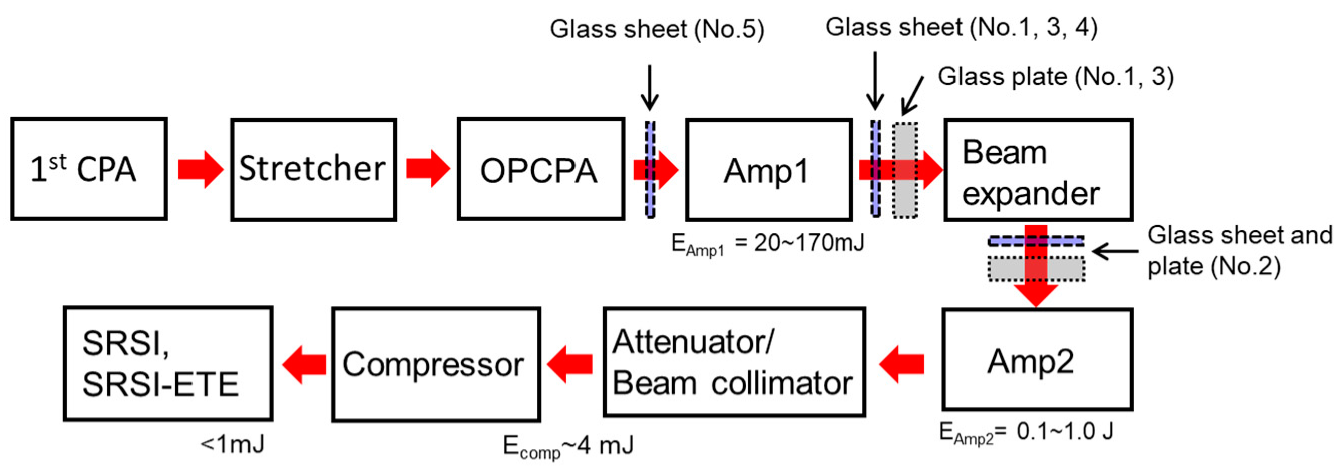
2.1. Laser System Layout and Experimental Condition

The experiment is performed using the J-KAREN-P laser system [25]. The layout of the laser system used in the experiment is presented in Figure 1. After the first CPA, the beam is amplified to ≈1.5 mJ by an optical parametric chirped-pulse amplifier after passing through a saturable absorber, stretcher and an acousto-optic programmable dispersive filter. The duration of the stretched pulse is 0.5 ns. The laser energy can be amplified to 1.0 J by Amp1 and Amp2. After the amplification, the laser energy is attenuated to 1.5 mJ. The beam size is reduced to a diameter of 5 mm and then compressed in the temporal domain by a compressor in air. The spectral bandwidth is 45 nm at full width at half maximum (FWHM) when operating at a central wavelength of 810 nm. The pulse width is measured using SRSI (Fastlite, WIZZLER). The pulse width is 48 ± 3 fs with FWHM. The error component is displayed as a standard deviation of 30 shots. In addition, the spectral and pulse widths are checked for each experimental condition. A glass sheet with a thickness of 0.15 ± 0.02 mm is installed almost perpendicular to the laser axis for generating the post-pulse. The locations where we insert the glass sheet differ according to the experimental conditions and are represented in Table 1. Note that a “glass sheet” is employed to generate the post-pulse, and “glass plates” are used to increase the B-integral value (see Figure 1).

2.2. Methods for Measurement of Temporal Contrast

The layout of the SRSI-ETE used in the experiment is the same as that applied in [23,24]. The laser energy of <1 mJ (beam diameter of 5 mm) is divided into a ratio of 1:9 by a beam splitter. The laser is led to the light path of the replica light (to be measured) and the light path for a cross-polarized wave (XPW) generation [26]. The pulse passes through a polarizer and is focused on a BaF2 crystal having a thickness of 1 mm by a spherical mirror. This generates the XPW, after which only the XPW is extracted by another polarizer. The replica pulse has an optical delay and is injected into a two-dimensional spectrometer (Princeton, Iso-Plane 320) along with the XPW light. Interference spectral images are obtained with a 16-bit CCD camera (Princeton, PIXIS). The temporal contrast can be obtained by taking the Fourier transform of the spectral interference into two dimensions [23]. The dynamic range used in this experiment is 106–107, which confirms that the measured time contrast is in good agreement with TOCC (Amplitude technology, SEQUOIA).

2.3. Method of Calculating the B-Integral

The B-integral of the main pulse is based on the length of all transmission media between the post-pulse-generating glass sheet and grating compressor. The laser intensity is calculated to a certain extent from the measurements of the beam diameter and energy. The stretched laser is assumed to have a top-hat configuration in both the time and spatial domains. In addition, the pulse duration is assumed to be 0.5 ns. Previous studies showed that the intensity and energy of a post-pulse-induced pre-pulse are proportional to the square of the accumulated B-integral of the main pulse [10,11,14]. To measure the relationship, two methods are used to increase the B-integral of the main pulse. One of these increases the B-integral of the main pulse by adding glass plates to the beamline while the other increases the energy of the pump laser to increase the energy of the main pulse.
In the former method, 1–7 glass plates are added to increase the medium length. The thickness of one piece is 6.35 mm, and it is composed of synthetic quartz. Both sides of the glass plate are coated with an anti-reflection coating (reflectivity of 1%) for the regions of the spectrum falling between 600 and 900 nm. The maximum reflection loss with seven pieces is ≈ 13%. The laser energy is adjusted to 14 and 23 mJ. The group velocity dispersion (GVD) increases, and the pulse width becomes longer owing to the inclusion of the transmission medium. Therefore, the spacing of the diffraction grating was adjusted to compensate for these effects.
The latter method increases the energy of the pump laser. The energy of the main pulse in Amp1 is varied from 6.6 to 56 mJ. Under another experimental condition, the energy is varied from 64 to 640 mJ by varying the energy of the Amp2 pump laser and measuring any significant changes. The experimental conditions and B-integral are detailed in Table 1.

2.4. Pre-Pulse Intensity Generated by the Post-Pulse

The energy of the pre-pulse generated by the post-pulse is represented by equation [9]:
Epre/E0 = a × B2 ×(Epost_0/E0 ),
where Epre, E0, and Epost_0 are the energies of the pre-pulse, main pulse, and post-pulse of multiple reflections with a glass sheet, respectively. In addition, B is the B-integral of the main pulse, and the value of “a” is approximately 0.2–0.6, although it depends on the shape of the pulse, as described in [10,15].
In contrast, if the pre- and post-pulses from the intensity modulation are generated symmetrically to the main pulse [14], the energy of the post-pulse after the compression is obtained as follows:
Epost = Epost_0 + Epre.
Here, Epost_0/E0 is expressed as E post_0/E0 = 1.14 × 10⁻³ in our estimation based on the Fresnel reflection. The increases in post- and pre-pulse owing to nonlinear effects are similar to the amplification process by four-wave mixing [27]. In the above case, it was assumed that the post- (Epost) and pre-pulse (Epre) are signal (seed) and idler pulse, respectively. The increases can be understood as follows. Each pulse is amplified by 1 + aB2, aB2 (energy ratio with E post_0) results from the effect of the SPM [27].

3. Results

First, the results of the pre-pulse generation caused by the post-pulse are illustrated in Figure 2. The figure displays the temporal contrast measured using SRSI-ETE. The vertical axis represents the normalized value at the maximum intensity and the horizontal axis indicates that the time of the peak intensity is zero. The gray and black lines in Figure 2 denote the time contrast results without and with the glass sheet, respectively, just before applying SRSI-ETE. The solid arrow represents a post-pulse (I of ≈ 1.3 × 10³) at +1.47 ps. The red line in Figure 2 denotes the case wherein a glass sheet is inserted before Amp1. Finally, the dotted arrow indicates a new pre-pulse generated at −1.47 ps.
Next, we describe the results of changing the B-integral with the addition of the glass plate. Figure 3a,b depicts the temporal contrast of the post- and pre-pulse, respectively. The intensity of the pre-pulse increases with an increase in the number of glass plates. In contrast, the post-pulse intensity does not increase compared to the pre-pulse intensity. Figure 3c illustrates the number of glass plates and the normalized energy of the pre- and post-pulses. The data points represent the average of 30 shots, and the error bars indicate the standard deviation. The data for the pre-pulse indicate that the intensities with seven glasses plates are higher than those without glass plates. The triangles in Figure 3c present the results when the glass sheet and glass plate are placed after the beam expander just before Amp2. In addition, the diameter of the beam increases from 4 to 13 mm. The energies of the pre-pulse do not increase even under the additional glass plates owing to a small change in the B-integral (see Table 1). Figure 4 exhibits the results at the main pulse energy of 23 mJ. In Figure 4c, the relationship between the normalized energy and the B-integral is illustrated. It is seen that the pre-pulse intensity increases with an increase in the B-integral.
We subsequently measured the change in the pre-pulse intensity for an increase in the laser energy output. A glass sheet was placed after Amp1 to generate a post-pulse, and the energy of the main pulse was varied from 6.6 to 56 mJ. Figure 5 indicates the temporal contrast of the post- and pre-pulses. As the energy of the main pulse increases, the intensity of the pre-pulse also increases. Furthermore, the result of the energy increase from 64 to 640 mJ with Amp2, as shown in Figure 6. As the energy of the pre-pulse is higher than that of the post-pulse, it is evident that the energy of the post-pulse increases with the pre-pulse.

4. Discussion

The thickness of the glass sheet is 0.15 ± 0.02 mm, and the refractive index n is 1.466 at a wavelength of 800 nm. The present delay of the post-pulse concerning the main pulse can be expressed by t = 2nd/c, where c denotes the speed of light and d represents the medium thickness. The delay is found to be t = 1.467 ± 0.196 ps. The experimental results in Figure 3a,b, Figure 4a,b, Figure 5a,b indicate that the post- and pre-pulse delay range from 1.46 to 1.48 ps and −1.44 to −1.48 ps, respectively, which exhibits good agreement with the estimates. The results show that pre- and post-pulses are generated symmetrically to the main pulse.
As indicated by the results in Figure 2, a new pre-pulse is generated by placing a glass sheet upstream from Amp1 for the post-pulse generation. The pre-pulse intensity is increased by an increase in the B-integral owing to an increase in the number of glass plates or, independently, the pulse energy, as shown in Figure 3, Figure 4, Figure 5 and Figure 6. From these two points, the measured pre-pulse at −1.47 ps is identified as a trend that is generated by the nonlinear effects of the main and post pulses in a CPA [10].
To clarify the trend in the energy increase of the pre-pulse for the experimental B-integral, the solid lines in Figure 4c, Figure 5c and Figure 6 denote an approximate curve based on the least-squares method of Equation (1), which is assumed to be Epost_0/E0 = 1.14 × 10⁻³. These results clearly indicate that the pre-pulse energy shown in Equation (1) is proportional to B2. In addition, the values of a in Equation (1) obtained from this approximation are 50, 26, and 3.5. The values of the fitting parameter “a” in each experimental condition (Nos. 4–6) are segregated by order-of-magnitude. Moreover, a difference of approximately 10- to 100-times the results of the previous studies is noted [10,15], the causes of which are not well understood but may be attributed to changes in the post-pulse intensity, differences in energy, or the uniformity of the spatial and temporal distributions [10]. For large and complex laser systems, such as the J-KAREN-P, it is difficult to accurately measure the total B-integral value. However, as shown in Figure 4c, Figure 5c and Figure 6, the increase in the B-integral with increasing glass plate and energy is found to be correct; therefore, the pre-pulse energy is proportional to B2.
As shown in Figure 3c, Figure 4c, Figure 5c and Figure 6, the normalized energy of the post-pulse is lower than 1.14 × 10⁻³ that was estimated from the Fresnel reflection. A potential explanation is that the surface roughness and flatness are of low quality because the parallel glass sheet is a cover glass for the microscope.
As indicated in Figure 6, the intensity of the post-pulse also tends to increase as the B-integral increases. Equation (2) of the post-pulse is denoted as a dashed line in Figure 6. On comparing the experimental results with the equation, the increasing trend of the post-pulse energy displays good agreement. When the post-pulse energy increases to above 5–6 × 10⁻⁴, the energy of the post-pulse increases with the pre-pulse, which suggests that the post-pulse and pre-pulse occur symmetrically with regard to the main pulse. When the B-integral is small, it is difficult to measure the post-pulse because it is lower than the intensity of the post-pulse owing to multiple reflections from the glass sheet. However, as the post-pulse of the nonlinear effects gets close to the reflected post-pulse, its intensity increases, similar to the pre-pulse. The increases in the post-pulse in our results are consistent with those reported in previous studies [14].

5. Conclusions

A post-pulse-induced pre-pulse generation was observed using the SRSI-ETE. The variation of each pulse was evaluated using SRSI-ETE based on the energy of each pulse per shot. The results indicate that the pre-pulse energy increases with the integrated B-integral, on increasing the laser energy and adding the transmission media. The experimental data clearly show that the pre-pulse energy increases in proportion to the square of the B-integral. The intensity of the post-pulse also increases, similar to the pre-pulse. These results exhibit good agreement with the equations presented in previous studies and are caused by a self-phase modulation owing to the optical Kerr effect. Such pre-pulses can adversely affect experiments. In recent years, many PW class lasers are in operation, and 10-PW laser systems [2,3] will be operational in a few years. Based on current achievements regarding the system, it has become essential to suppress the B-integral and the post-pulse generated in physics experiments that require a high temporal contrast.

Author Contributions

Conceptualization, A.K., M.N. and H.K.; methodology, A.K., M.N., H.K., S.B., T.Z., T.P.; software, S.B., T.Z., T.P.; validation, A.K., M.N., H.K.; formal analysis, A.K.; investigation, A.K., M.N., H.K., S.B., T.Z., T.P. and K.Z.; writing—original draft preparation, A.K.; writing—review and editing, M.N., H.K., M.K.; visualization, A.K.; supervision, M.K.; project administration, U.S. and K.K.; funding acquisition, K.K. All authors have read and agreed to the published version of the manuscript.

Funding

This research was funded by JST-Mirai Program Grant Number JPMJMI17A1, Japan, and QST President’s Strategic Grant (QST International Research Initiative (AAA98) and Creative Research (ABACS)).

Acknowledgments

The authors acknowledge the contributions by the Kansai Photon Science Institute staff at the National Institutes for Quantum and Radiological Science. We would like to thank Editage (www.editage.com) for English language editing.

Conflicts of Interest

The authors declare no conflict of interest.

References

  1. Strickland, D.; Mourou, G. Compression of amplified chirped optical pulses. Opt. Commun. 1985, 56, 219–221. [Google Scholar] [CrossRef]
  2. Extreme Light Infrastructure. Available online: https://eli-laser.eu/ (accessed on 1 June 2020).
  3. Danson, C.; Hillier, D.; Hopps, N.; Neely, D. Petawatt class lasers worldwide. High Power Laser Sci. Eng. 2015, 3, 3. [Google Scholar] [CrossRef]
  4. Kaluza, M.; Schreiber, J.; Santala, M.I.K.; Tsakiris, G.D.; Eidmann, K.; Meyer-Ter-Vehn, J.; Witte, K.J. Influence of the Laser Prepulse on Proton Acceleration in Thin-Foil Experiments. Phys. Rev. Lett. 2004, 93, 045003. [Google Scholar] [CrossRef] [PubMed]
  5. Metzkes-Ng, J.; Kluge, T.; Zeil, K.; Bussmann, M.; Kraft, S.; Cowan, T.E.; Schramm, U. Experimental observation of transverse modulations in laser-driven proton beams. New J. Phys. 2014, 16, 23008. [Google Scholar] [CrossRef] [Green Version]
  6. Mangles, S.P.D.; Thomas, A.; Kaluza, M.C.; Lundh, O.; Lindau, F.; Persson, A.; Najmudin, Z.; Wahlström, C.-G.; Murphy, C.D.; Kamperidis, C.; et al. Effect of laser contrast ratio on electron beam stability in laser wakefield acceleration experiments. Plasma Phys. Control. Fusion 2006, 48, B83–B90. [Google Scholar] [CrossRef]
  7. Ivanov, V.V.; Maksimchuk, A.; Mourou, G. Amplified spontaneous emission in a Ti:sapphire regenerative amplifier. Appl. Opt. 2003, 42, 7231–7234. [Google Scholar] [CrossRef]
  8. Kane, S.; Squier, J. Fourth-order-dispersion limitations of aberration-free chirped-pulse amplification systems. J. Opt. Soc. Am. B 1997, 14, 1237–1244. [Google Scholar] [CrossRef]
  9. Hooker, C.; Tang, Y.; Chekhlov, O.; Collier, J.; Divall, E.; Ertel, K.; Hawkes, S.; Parry, B.; Rajeev, P.P. Improving coherent contrast of petawatt laser pulses. Opt. Express 2011, 19, 2193–2203. [Google Scholar] [CrossRef]
  10. Didenko, N.V.; Konyashchenko, A.V.; Lutsenko, A.; Tenyakov, S.Y. Contrast degradation in a chirped-pulse amplifier due to generation of prepulses by postpulses. Opt. Express 2008, 16, 3178. [Google Scholar] [CrossRef]
  11. Jackson, M.K.; Boyer, G.R.; Paye, J.; Franco, M.A.; Mysyrowicz, A. Temporal diffraction by nonlinear interaction in optical fibers. Opt. Lett. 1992, 17, 1770–1772. [Google Scholar] [CrossRef]
  12. Liu, X.; Wagner, R.; Maksimchuk, A.; Goodman, E.; Workman, J.; Umstadter, D.; Migus, A. Nonlinear temporal diffraction and frequency shifts resulting from pulse shaping in chirped-pulse amplification systems. Opt. Lett. 1995, 20, 1163–1165. [Google Scholar] [CrossRef] [PubMed] [Green Version]
  13. Perry, M.D.; Ditmire, T.; Stuart, B.C. Self-phase modulation in chirped-pulse amplification. Opt. Lett. 1994, 19, 2149–2151. [Google Scholar] [CrossRef] [PubMed]
  14. Schimpf, D.N.; Seise, E.; Limpert, J.; Tünnermann, A. The impact of spectral modulations on the contrast of pulses of nonlinear chirped-pulse amplification systems. Opt. Express 2008, 16, 10664–10674. [Google Scholar] [CrossRef]
  15. Kalashnikov, M.; Andreev, A.; Schönnagel, H. Limits of the temporal contrast for CPA lasers with beams of high aperture. Ultrafast Nonlinear Opt. 2009, 7501, 750104. [Google Scholar] [CrossRef]
  16. Keppler, S.; Hornung, M.; Bödefeld, R.; Kahle, M.; Hein, J.; Kaluza, M.C. All-reflective, highly accurate polarization rotator for high-power short-pulse laser systems. Opt. Express 2012, 20, 20742–20747. [Google Scholar] [CrossRef] [PubMed]
  17. Khodakovskiy, N.; Kalashnikov, M.; Gontier, E.; Falcoz, F.; Paul, P.-M. Degradation of picosecond temporal contrast of Ti:sapphire lasers with coherent pedestals. Opt. Lett. 2016, 41, 4441. [Google Scholar] [CrossRef]
  18. Kiriyama, H.; Miyasaka, Y.; Sagisaka, A.; Ogura, K.; Nishiuchi, M.; Pirozhkov, A.S.; Fukuda, Y.; Kando, M.; Kondo, K. Experimental investigation on the temporal contrast of pre-pulses by post-pulses in a petawatt laser facility. Opt. Lett. 2020, 45, 1100–1103. [Google Scholar] [CrossRef]
  19. Schimpf, D.; Seise, E.; Limpert, J.; Tünnermann, A. Decrease of pulse-contrast in nonlinear chirped-pulse amplification systems due to high-frequency spectral phase ripples. Opt. Express 2008, 16, 8876. [Google Scholar] [CrossRef]
  20. Khodakovskiy, N. Methods of Ultra-Fast Laser Contrast Diagnostics and Optimization. Ph.D. Thesis, Free University of Berlin, Berlin, Germany, 2020. [Google Scholar]
  21. Luan, S.; Hutchinson, M.H.R.; Smith, R.A.; Zhou, F. High dynamic range third-order correlation measurement of picosecond laser pulse shapes. Meas. Sci. Technol. 1993, 4, 1426–1429. [Google Scholar] [CrossRef]
  22. Oksenhendler, T.; Coudreau, S.; Forget, N.; Crozatier, V.; Grabielle, S.; Herzog, R.; Gobert, O.; Kaplan, D. Self-referenced spectral interferometry. Appl. Phys. A 2010, 99, 7–12. [Google Scholar] [CrossRef]
  23. Oksenhendler, T.; Bizouard, P.; Albert, O.; Bock, S.; Schramm, U. High dynamic, high resolution and wide range single shot temporal pulse contrast measurement. Opt. Express 2017, 25, 12588. [Google Scholar] [CrossRef] [PubMed]
  24. Kiriyama, H.; Pirozhkov, A.S.; Nishiuchi, M.; Fukuda, Y.; Ogura, K.; Sagisaka, A.; Miyasaka, Y.; Mori, M.; Sakaki, H.; Dover, N.P.; et al. High-contrast high-intensity repetitive petawatt laser. Opt. Lett. 2018, 43, 2595–2598. [Google Scholar] [CrossRef] [PubMed]
  25. Obst, L.; Metzkes-Ng, J.; Bock, S.; Cochran, G.E.; Cochran, T.E.; Oksenhendler, T.; Poole, P.L.; Prencipe, I.; Rehwald, M.; Rödel, C.; et al. On-shot characterization of single plasma mirror temporal contrast improvement. Plasma Phys. Control. Fusion 2018, 60, 054007. [Google Scholar] [CrossRef] [Green Version]
  26. Jullien, A.; Canova, L.; Albert, O.; Boschetto, D.; Antonucci, L.; Cha, Y.-H.; Rousseau, J.; Chaudet, P.; Cheriaux, G.; Etchepare, J.; et al. Spectral broadening and pulse duration reduction during cross-polarized wave generation: Influence of the quadratic spectral phase. Appl. Phys. A 2007, 87, 595–601. [Google Scholar] [CrossRef]
  27. Heebner, J.E.; Acree, R.L., Jr.; Alessi, D.; Barnes, A.I.; Bowers, M.W.; Browning, D.F.; Budge, T.S.; Burns, S.; Chang, L.S.; Christensen, K.S.; et al. Injection laser system for Advanced Radiographic Capability using chirped pulse amplification on the National Ignition Facility. Appl. Opt. 2019, 58, 8501–8510. [Google Scholar] [CrossRef] [PubMed]
Figure 1. Experimental setup in J-KAREN-P. After the first chirped pulse amplification (CPA) and stretcher, the laser pulse is amplified with the optical parametric chirped-pulse amplifier (OPCPA) and Amp1 and Amp2 of the multi-pass amplifier. A glass sheet (0.15 mm thick) for post-pulse generation is placed between OPCPA and Amp1, or between Amp1 and Amp2. The glass plate (6.35 mm thick) is placed for increasing the B-integral value. The Nos indicate the experimental condition in Table 1. The temporal contrast is measured with self-referenced spectral interferometry (SRSI) and self-referenced spectral interferometry with extended time excursion (SRSI-ETE) after the compressor.
Crystals 10 00657 g001
Figure 2. Measured temporal contrast without a glass sheet (gray line) and with a glass sheet before SRSI-ETE (black line) and before Amp1 (red dashed line). The solid and dotted arrows indicate the post- and pre-pulses with the glass sheet at +1.47 and −1.47 ps.
Crystals 10 00657 g002
Figure 3. (a,b) Temporal contrast for the pre- and post-pulses and (c) normalized energy of pre- and post-pulses with the addition of a glass sheet at a laser energy of 14 mJ. The values in (a,b) indicate the number of glass plates. The experimental conditions are listed as Nos. 1 and 2 in Table 1.
Crystals 10 00657 g003
Figure 4. (a,b) Temporal contrast for the pre- and post-pulses and (c) normalized energy of pre- and post-pulses with the addition of a glass sheet at a laser energy of 23 mJ. The values in (a,b) indicate the number of glass plates. The experimental conditions are listed as No. 3 in Table 1. The solid line indicates the results of the approximate curves with Equation (1). The dashed line indicates the post-pulse energy of Equation (2).
Crystals 10 00657 g004
Figure 5. (a,b) Temporal contrast for the pre- and post-pulses, and (c) normalized energy of pre- and post-pulses when increasing the laser energy of the main pulse from 6.6 to 56 mJ. The experimental condition is shown as No. 4 in Table 1. The solid line indicates the results of the approximate curves with Equation (1). The dashed line indicates the post-pulse energy of Equation (2).
Crystals 10 00657 g005
Figure 6. Normalized pre- and post-pulse energies at the B-integral from 6.6 to 640 mJ of laser energy. The solid line indicates the results of the approximate curves with Equation (1). The dashed line indicates the post-pulse energy of Equation (2). The experimental condition is shown as No. 5 in Table 1.
Crystals 10 00657 g006
Table 1. Experimental conditions when investigating the pre-pulse intensity in response to a variation of the B-integral. In the experiment of Nos. 1–3, the B-integral value is increased by adding the glass plates. The maximum reflection loss with seven pieces is ≈ 13%. In Nos. 4 and 5, the B-integral value is increased by increasing the laser energy. Note that in Nos. 4 and 5, no glass plate is added.
No.Location of Glass SheetLaser Energy after Amp2 (mJ)Pumped AmplifierNumber of Glass PlatesB-Integral (rad)
1After Amp112–14Amp10–73.6–7.6 × 10⁻²
2After beam expander12–14Amp10–72.3–2.4 × 10⁻²
3After Amp120–23Amp10–75.7–12 × 10−2
4After Amp16.6–56Amp1N/A1.6–14 × 10−2
5Before Amp16.4–640Amp1 and 2N/A1.0–8.0 × 10−1

