Article

Facile Synthesis of Ultralight and Porous Melamine-Formaldehyde (MF) Resin-Derived Magnetic Graphite-Like C3N4/Carbon Foam with Electromagnetic Wave Absorption Behavior

1
College of Materials Science and Engineering, Nanjing Forestry University, Nanjing 210037, China
2
Jiangsu Co-Innovation Center of Efficient Processing and Utilization of Forest Resources, Nanjing 210037, China
*
Author to whom correspondence should be addressed.
Crystals 2020, 10(8), 656; https://doi.org/10.3390/cryst10080656
Submission received: 6 July 2020 / Revised: 26 July 2020 / Accepted: 29 July 2020 / Published: 30 July 2020
(This article belongs to the Section Hybrid and Composite Crystalline Materials)

Abstract

:
Society demands effective electromagnetic wave (EMW) absorbers that are lightweight, with a broad absorption band and strong absorption, to solve excessive electromagnetic radiation. Herein, ultralight magnetic graphite-like C3N4/carbon foam (MCMF) was fabricated via impregnating polymerized melamine formaldehyde (MF) foams in Fe3O4 nanoparticle solution, followed by in situ pyrolysis at 1000 °C. MCMF possesses porous architectures consisting of graphitic C3N4/carbon and CFe15.1. The magnetic particles (α-Fe, Fe3O4 and Fe3C) were formed and modified on the internal skeleton surface. The EMW absorption capacity of MCMF is better than the that of carbonized MF foam without Fe3O4 (CMF), possessing excellent absorption behavior, with a minimum RL value of −47.38 dB and a matching thickness as thin as 3.90 mm. The corresponding effective absorbing bandwidth is as broad as 13.32 GHz. Maxwell–Wagner–Sillars (MWS) polarization and the residual loss are proved to be beneficial for such superior absorption behavior. Besides, graphitic C3N4 enriches the interface polarization effect and the electromagnetic matching effect. The microporous structures are beneficial for increasing EMW propagation, resulting in internal multiple reflections and scatterings, which are also beneficial for EMW attenuation.

1. Introduction

Excessive electromagnetic radiation not only harms human health but also affects the natural environment on which human beings depend [1,2]. For example, serious electromagnetic pollution has an impact on plants, resulting in their abnormal growth, gene mutation and even death [3,4]. Besides, electromagnetic radiation can also cause adverse effects on livestock and wildlife. To avoid such a situation, society needs effective electromagnetic wave (EMW) absorbers that are lightweight, with a broad absorption band and strong absorption capacity, which can be applied to reduce the undesirable electromagnetic wave emissions [5,6,7].
Recently, graphitic carbon nitride (g-C3N4) has been widely used in the fields of photocatalysis, gas storage and fuel cells, attributed to its appropriate band gap, unique optical properties, gas adsorption capacity and superior chemical/thermal stability [8,9,10,11]. The high electron-hole rate of g-C3N4 should ensure its corresponding superior electronic properties under the combined action of sp2-hybridized C and N with π-conjugated electronic systems [12,13]. Enhanced electronic properties imply better EMW absorption performance with a thinner matching thickness and stronger absorption capacity [2,14,15]. On the other hand, Fe content results in a higher Snoek’s limit and essential magnetization, ensuring a strong absorption capacity at GHz [16]. Based on this, it is possible for us to use g-C3N4 to fabricate composites with magnetic materials to construct novel excellent EMW absorbers. However, there is little related research.
g-C3N4 prepared by high-temperature roasting possesses a low surface area (~10 m2/g), attributed to graphitic layer agglomeration [17,18]. As far as we know, a high surface area consisting of solid skeletons and air cavities is beneficial for increasing electronic transmission speed and enriching the multiple reflection and absorption paths for EMWs [19,20,21]. The dielectric–magnetic impedance matching can be enhanced by modifying these porous conductive matrices with Fe-containing particles [22,23]. Besides, dispersing smaller and isolated particles with sizes less than their skin depth can suppress the corresponding eddy current phenomenon, resulting in excellent EMW absorption [24]. Considering this, magnetic porous conductive composites have drawn great interest from scientists in the field of EMW absorption, and carbon-based composites account for a large part [25,26,27,28]. Thus, developing facile and effective methods of facially synthesizing porous, magnetic, carbon-based composites with excellent EMW absorption capacities is urgently needed. To date, it has remained a challenge to disperse magnetic nanoparticles in porous g-C3N4/C matrix materials.
Porous materials can normally be divided into two types: aerogels and foams. Among them, melamine formaldehyde (MF) is a suitable precursor because of its ability to be prepared from cheap raw materials and the flexible functional groups in MF molecules [29,30]. Here, porous magnetic MF-derived g-C3N4/g-carbon foam (MCMF) was fabricated via impregnating the prepared MF foams in Fe3O4 nanoparticle solution and the following in situ carbonization process. The magnetic particles of nano-size were observed to be evenly dispersed on the porous framework. MCMF exhibits excellent EMW absorption properties including a strong absorption capacity, low density, broad effective frequency range and relatively thin matching thickness. The corresponding absorption mechanism was also explored.

2. Materials and Methods

2.1. Materials

Melamine (99%) and formaldehyde–water solution (37 wt%) were provided as analytically pure reagents by Kelong Chemical Regents Co., Ltd. (Chengdu, China). Sodium hydroxide (NaOH), formic acid, sodium dodecyl benzenesulfonate (SDBS), triethanolamine and pentane were all purchased from Aldrich (Darmstadt, Germany). Ferric chloride hexahydrate (FeCl3·6H2O), ferrous chloride tetrahydrate (FeSO4·7H2O) and ammonium hydroxide were of analytical grade and purchased from Sigma Aldrich (St. Louis, MO, USA). All aqueous solutions were prepared with deionized water.

2.2. Melamine Formaldehyde (MF) Foam Synthesis

Amounts of 7.56 g of melamine and 14.20 g of formaldehyde solution were added to 20 mL of distilled water and heated at 70 °C for 1 h. Then, the pH value of the mixture was adjusted to 8.5 by dripping triethanolamine into it. After that, the mixture was further heated at 80 °C for another 3 h to obtain the resultant MF resin. The synthesized MF resin was then compounded with SDBS (1%) as an emulsifier and with pentane (3%) as a foaming agent with a high-speed mechanical mixer. Formic acid was also added into the mixture as a curing catalyst, and it was stirred for 1 min. Finally, the obtained viscous mixture was transferred into a foaming mold, followed by curing and foaming in an oven at 80 °C for 15 min, and elastic MF foam was obtained.

2.3. Magnetic g-C3N4/g-Carbon Foam (MCMF) Synthesis

Firstly, the Fe3O4 magnetic nanoparticles were prepared by the coprecipitation method. Briefly, 2.35 g of FeSO4·7H2O and 4.1 g of FeCl3·6H2O were dissolved into 100 mL of deionized water in a flask, followed by 30 min of violent stirring at 80 °C. Then, 25 mL of NH3·H2O (25%, w/w) was quickly added into the mixture, and the mixture was continually stirred for another 1.5 h. All these processes were performed under N2 protection. The products were washed with hot deionized water three times and were re-dispersed in aqueous solution.
After that, the prepared MF foams were impregnated in Fe3O4 solution, followed by repeated pressing to ensure the adequate absorption of the impregnating solutions (Figure 1A). Then, the impregnated specimens were seasoned under a natural state for 1 h, followed by air-drying at 55 °C for another 4 h. Then, magnetic MF foam was obtained and named as MMF. In succession, MFs and MMFs were placed into a tube furnace under N2 flow. After the air was purged and N2 was filled in the furnace for 30 min, the samples were heated to 1000 °C at a heating rate of 5 °C/min and kept for 4 h (Figure 1A). After the pyrolysis process, the samples were cooled to ambient temperature and named as carbonized MF foam without Fe3O4 (CMF) and MCMF, respectively.

2.4. Characterization of Synthesized Samples

The morphology of Fe3O4 nanoparticles was characterized by transmission electron microscopy (TEM, FEI Tecnai G2 20 S-TWIN, OR, USA). The morphologies of the foam samples were observed by scanning electron microscopy (SEM, JSM-7800F, JEOL Ltd., Toyoshima, Tokyo, Japan) after they were sliced in liquid nitrogen to produce cross-sections. The X-ray diffraction (XRD) patterns with a 2θ scanning range of 10–80° were obtained on an X-ray diffractometer (Bruker, Germany) using Cu-Ka radiation (λ = 1.54 Å). The X-ray photoelectron spectroscopy (XPS) spectrum was measured in an AXIS UltraDLD (Shimadzu, Japan) using an Al Ka X-ray source and operation at 150 W. Magnetic measurements were carried out using a Vibrating Sample Magnetometer (VSM) (Lake Shore 7407, East Changing Technologies, Inc., Beijing, China) with a sample mass of 10 mg.
Samples of 15 wt% were mixed with paraffin and pressed into toroidal shapes (Φout: 7.0 mm, Φin: 3.04 mm) using a pre-designed mold for electromagnetic parameter measurement. The relative complex permittivities (ε’, ε’’) and relative complex permeabilities (μ’, μ’’) of the specimens were measured by the coaxial-line method with an Agilent PNA N5224A vector network analyzer in the frequency range of 2–18 GHz. Finally, the electromagnetic-wave-absorbing performance of the specimens could be evaluated by the reflection loss (RL), which can be defined by equations on the basis of transmission line theory [31].

3. Results and Discussion

3.1. Characterization of the Samples

As shown in Figure 1B, the prepared Fe3O4 particles were observed through TEM to possess a size distribution of 12.21 ± 0.07 nm. From Figure 1C, we may see that the MF foam could recover its original shape and size after extrusion, indicating its good elasticity, which ensured its basic morphology after the absorption of the Fe3O4 nanoparticle solution. Figure 1D shows the SEM images of the cross-sectional morphologies of the CMF along with the corresponding C, O, N and Fe elemental EDS mapping images, respectively. It is obvious that the CMF shows a solid 3D-foam architecture consisting of interconnected cells with narrow and smooth ligaments, which mainly consist of C and N elements. However, no Fe signal is observed in Figure 1D. Figure 1E shows a physical photo of MCMF, which was obtained via the pyrolysis of MMF at 1000 °C. It is obvious that the pyrolyzed foam shows a similar shape and dimension to the MF foam, with an ultralight bulk density of only 0.32 g/cm3. Figure 1F shows the SEM micrographs of the cross-sectional morphologies of the MCMF along with the corresponding C, O, N and Fe elemental EDS mapping images, respectively. These are dramatically different from those of the CMF; signals of the Fe element are present and observed to be located at the same points as the localizations of the obtained particles in Figure 1F(2). These particles are observed to be embedded in the ligaments of the matrix, grow along the surface of the skeletons and spread throughout the skeletons.
XRD was introduced to investigate the crystalline structures of the MMF and MCMF as shown in Figure 2. From the XRD curves, we may observe the peaks at 2θ = 29.62°, 34.90°, 42.36°, 56.42° and 62.12°, which represent the (220), (311), (400), (511) and (440) planes of Fe3O4 in a cubic phase (JCPDS 16-629), respectively [32], indicating the adsorption of Fe3O4 nanoparticles inside the MF foams after the impregnation process. After being pyrolyzed, the obtained MCMF displays a distinct XRD curve. Due to the pyrolysis and graphitization of the resin foam during the pyrolysis processes, the combined diffraction peaks of the (002) plane of graphitic C3N4 (JCPDS 87-1526) and the (111) plane of graphite crystalline carbon (JCPDS 75-0444) are observed at 2θ = 26.26° [33]. The presence of Fe3C is proved by the observed peaks at 2θ = 37.62°, 39.72°, 40.54°, 42.84°, 43.70°, 45.82°, 48.54°, 48.98°, 51.76°, 54.34°, 55.90°, 57.88° and 70.66°, corresponding to the (210), (200), (201), (211), (102), (310), (131), (221), (122), (230), (212), (301) and (123) planes (JCPDS 35-0772), respectively [34]. The peaks at 2θ = 44.60° and 64.90° are observed for MCMF, corresponding to the (110) and (200) planes of alpha-Fe (JCPDS 06-0696). These peaks indicate the transformation of the adsorbed Fe3O4 nanoparticles into Fe3C and alpha-Fe during the pyrolysis. The obvious peaks at 2θ = 29.62°, 34.90° and 62.12° indicate that complete phase transformation cannot be achieved in the pyrolysis process and the MCMF still consists of a certain amount of Fe3O4. It is worth noting that the peak corresponding to the (200) plane of CFe15.1 (JCPDS 52.0512) is observed at 2θ = 50.80°, indicating the formation of austenite, which is a kind of solid solution consisting of metallic iron and partially infiltrating carbon.
It is difficult to determine the presence of graphitic C3N4 and graphitic carbon in one composite simply with XRD tests since these two different phases have a diffraction peak in common at 2θ = ~26.00°. The coexistence of g-C3N4 and g-carbon can be proved according to the obtained results from the XPS measurements because the core electron lines of N1s and C1s can be detected and distinguished from each other by XPS. According to the survey XPS curves for CMF and MCMF in Figure 3A, MCMF consists of Fe and O elements while no Fe/O signal is observed for CMF. This is consistent with the XRD results. Figure 3B–D are the high-resolution XPS spectra of C1s, Fe2p and N1s, respectively. As shown in Figure 3B, the C1s spectra of the two samples both have five deconvoluted binding energy peaks at ~284.5, ~285.0, ~286.0, ~288.0 and ~288.5 eV, corresponding to adventitious carbon C=C and C-C bonds, and N-C=N, C-N3 and N-C-O bonds, respectively. Among these bonds, we may find that from CMF to MCMF, the intensity ratio of C=C/C-C increases from 0.53 to 0.68, indicating the enhanced transformation from amorphous C structures to regular graphitic stacks under the catalysis of existent Fe and Fe3O4, which is supposed to be conducive to enhanced conductivity. As shown in Figure 3C, the spectra of the Fe2p of MCMF are deconvoluted into five peaks at ~711.9, ~708.8, ~720.0, ~725.0 and ~711.0 eV, corresponding to the characteristic doublet from Fe 2p3/2 and Fe 2p1/2 core-level electrons of Fe3C, Fe 2p1/2 core-level electrons of α-Fe, and Fe 2p3/2 and Fe 2p1/2 core-level electrons of Fe3O4, respectively [35,36]. Additionally, the N1s spectra of the two samples can be divided into two peaks as shown in Figure 3D. The peaks located at ~398.6 and ~400.2 eV are assigned to the sp2 hybrid N atom in the formation of C-N=C and the N-(C)3 bond in g-C3N4 [37]. By now, we can conclude that the particles observed in Figure 1F should be composites consisting of alpha-Fe, Fe3C or Fe3O4, and the skeletons consist of g-C3N4 and g-carbon. Since magnetic fillers are proved to be incorporated in the composite foam, the magnetic properties of MCMF were investigated by VSM, and corresponding results are shown in Figure 4. It is obvious from Figure 4 that MCMF exhibits a typical hysteresis loop with a saturation magnetization value of 43.00 emu/g, indicating its excellent magnetic properties [38].

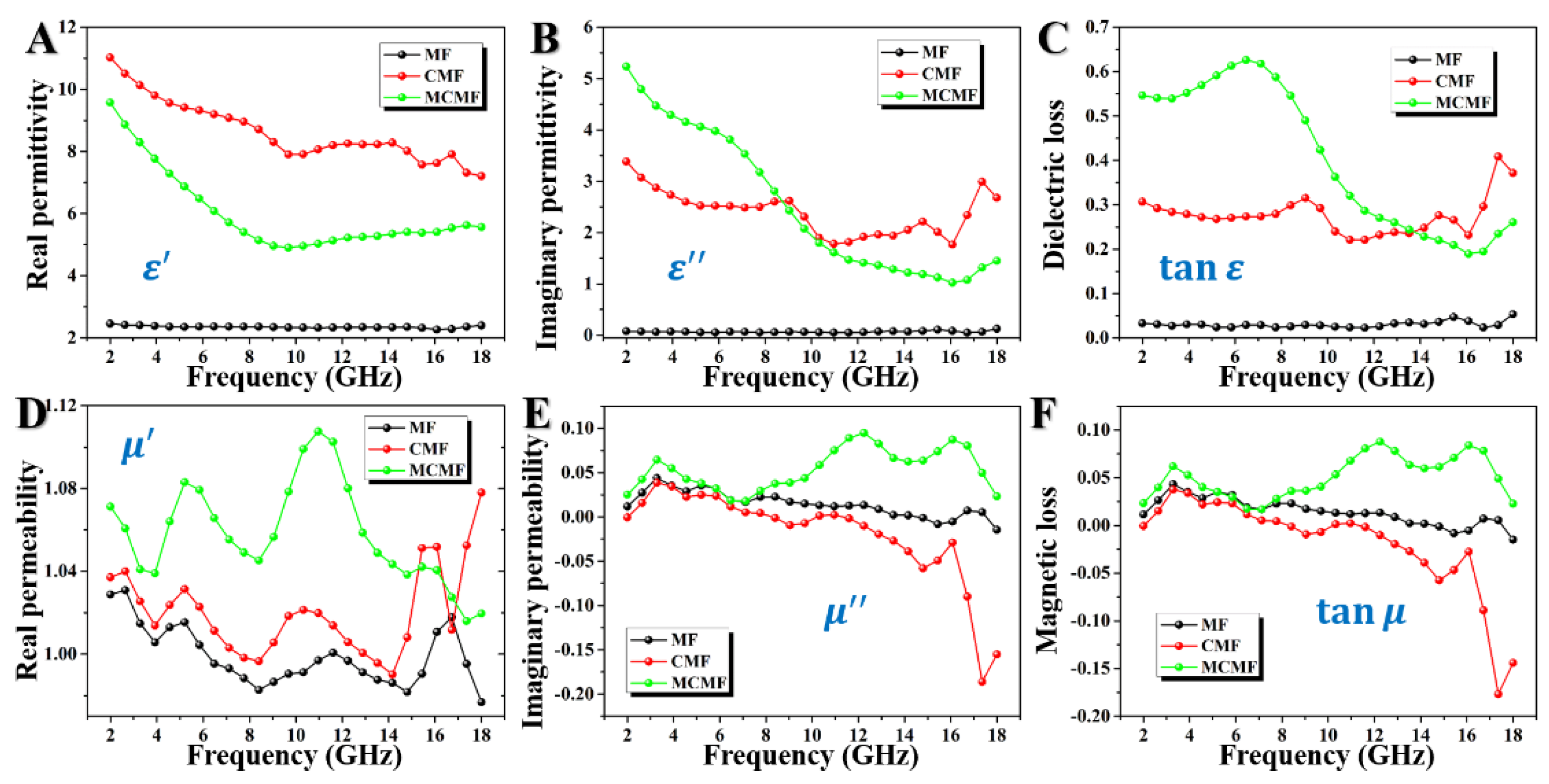
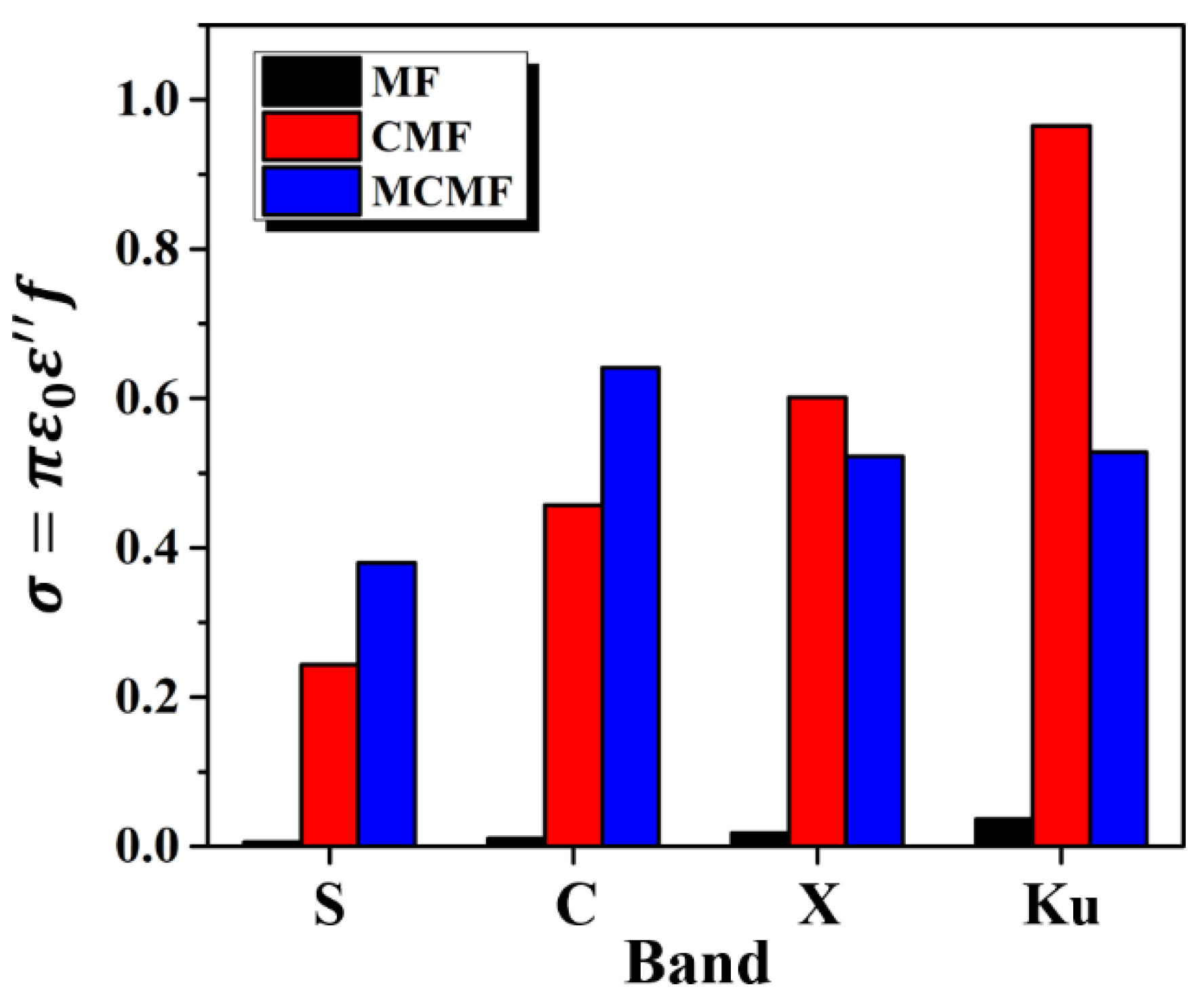
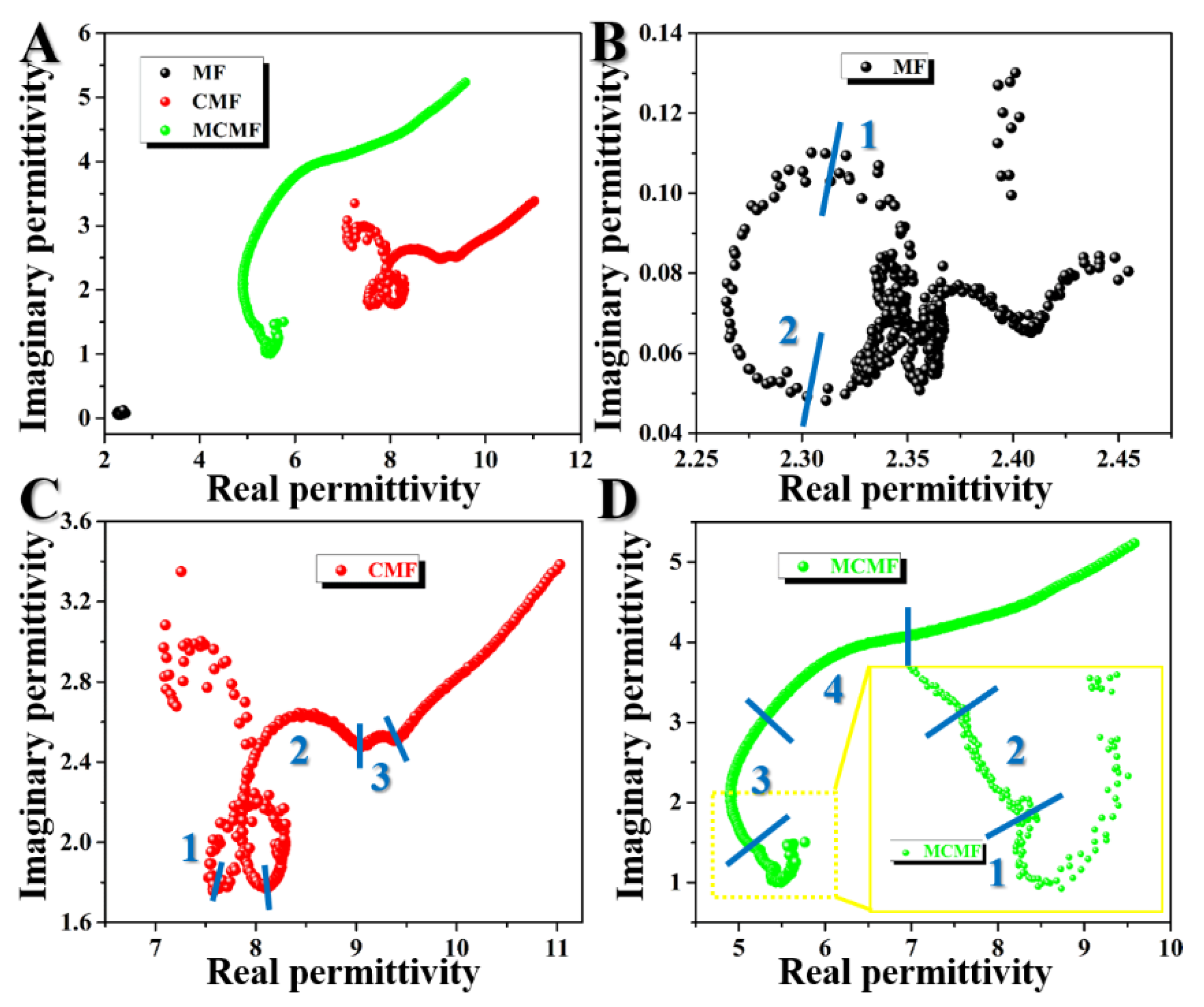
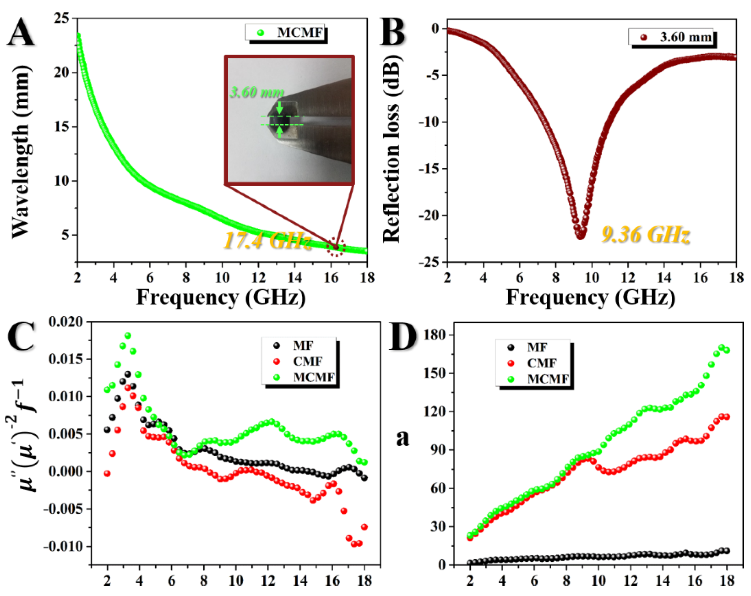
3.2. Electromagnetic Properties of the Samples

According to the following equations on the basis of transmission line theory:
Z i n = Z 0 ( μ r / ε r ) 1 / 2 tan h [ j ( 2 π fd / c ) ( μ r ε r ) 1 / 2 ]
R L = 20 l o g 10 | ( Z i n Z 0 ) / ( Z i n + Z 0 ) |
where Z0 is the characteristic impedance of free space, Zin is the input impedance of the absorber, εr is the relative complex permittivity ( ε r = ε j ε ), μr is the relative complex permeability ( μ r = μ j μ ), f is the frequency of the microwaves, d is the thickness of the specimen and c is the velocity of light, the EMW absorption capacities of the absorbers are related to ε r and μ r . Figure 5A,B show the ε and ε values for MF, CMF and MCMF, representing their electrical storage and loss capabilities, respectively. It is obvious in Figure 5A that among the three samples, MCMF possesses a medium ε value, ranging from 9.58 to 4.91, implying its good polarization degree under the electromagnetic field. Its lower ε value compared to CMF is attributed to the formed Fe3C with lower conductivity. We can also see from Figure 5B that the imaginary permittivity of MCMF is highly dependent on the frequency. When f < 9 GHz, the corresponding ε’’ value is larger than that of CMF, indicating its largest loss capacity for EMW energy due to the internal electric dipole moments’ rearrangement during the propagation of the EMW. However, when f > 9 GHz, the imaginary permittivity of MCMF falls below that of CMF. This is supposed to be attributable to the modification of iron-containing particles inside the g-C3N4/C matrix. Figure 6 displays the electrical conductivities of the absorbers over the frequency range from the S band to Ku band, indicating that inorganic hybridization and N-doping both have great impacts on the electrical conductivity. The dielectric-loss tangent:
tan δ ε = ε ε = σ ω ε 0 ε
is usually used to estimate the dielectric loss property of the absorbers, where δ ε , σ, ω and ε0 are the lag phase of the inductance field D relative to the external electric field, the conductivity, the angular frequency of the absorber and the conductivity constant (8.854 × 10⁻¹² F/m), respectively. As shown in Figure 5C, MCMF possesses the highest tan δ ε value of 0.63 at 6.48 GHz, indicating its corresponding largest capacities for converting the EMW energy to energy of other forms.
The μ value represents the magnetic loss capacity of the absorbers. As shown in Figure 5D, MCMF shows the highest μ of 1.11 at 10.96 GHz among the three absorbers. Meanwhile, MCMF also possesses the highest μ value of 0.10 at 12.24 GHz (Figure 5E), indicating its corresponding largest EMW energy loss due to the internal magnetic dipole moments’ rearrangement under the alternating magnetic field. Based on the electrodynamic theory, fabricating materials with relatively large ε and μ values is an effective way to devise excellent EMW absorbers since the imaginary parts of permittivity and permeability cannot be neglected and, thus, are responsible for the absorption behavior. The variation of the magnetic loss values is determined according to the following equation:
tan δ μ = μ / μ
and is shown in Figure 5F. We can see from Figure 5F that the corresponding variation is in accordance with that of the μ values, and MCMF possesses the largest tangent value of 0.088 at 12.24 GHz. This lower value of magnetic loss tangent than dielectric loss tangent implies the dominant role of the dielectric loss in the EMW energy attenuation.
However, multiple polarization relaxation processes should be considered to occur during the incoming electromagnetic field, due to the co-presence of dielectric phases (α-Fe, austenite, g-C3N4 and g-carbon) and magnetic phases (Fe3O4 and Fe3C). According to the Debye relaxation theory, the corresponding dielectric loss mechanisms can be investigated using the equation below [39]:
( ε ε s + ε 2 ) 2 + ( ε ) 2 = ( ε s ε 2 ) 2
where ε s and ε are the static permittivity and relative permittivity in the higher frequency region, respectively. The plot of ε versus ε is supposed to be a single semicircle termed as the Cole–Cole semicircle, with each semicircle corresponding to a Debye relaxation process. The Cole–Cole curves of MF, CMF and MCMF are shown in Figure 7. It is obvious that MF displays only two Cole–Cole semicircles and CMF displays only three Cole–Cole semicircles while MCMF displays four Cole–Cole semicircles with clear outlines. The observed plots of ε versus ε shift to lower values from CMF to MCMF, implying a reduced contribution of Debye relaxation to dielectric loss. This is also attributed to the formation of Fe3C with lower conductivity in the MCMF after the pyrolysis process. However, compared with for CMF, the semicircle morphologies are not regular for MCMF, which has been proved to possess the largest dielectric loss and magnetic loss capacities (Figure 5C,F). This is attributed to the fact that due to the presence of more conductive α-Fe, g-C3N4 and g-carbon resulting in a decrease in skin depth, a part of the EMW energy converts into microcurrent at the interface between the absorber and air, and thus, fewer interface polarization processes happen. This irregular characterization of semicircle morphology reveals that other polarization processes should act on the EMW absorption behavior. For example, Maxwell–Wagner–Sillars (MWS) polarization is normally supposed as a significant polarization mechanism in multi-component heterogeneous media [40]. Additional charge accumulations should occur at the interfaces of multiple phases under external EM fields in such heterostructures since these phases are different in terms of the ability to hold charges.

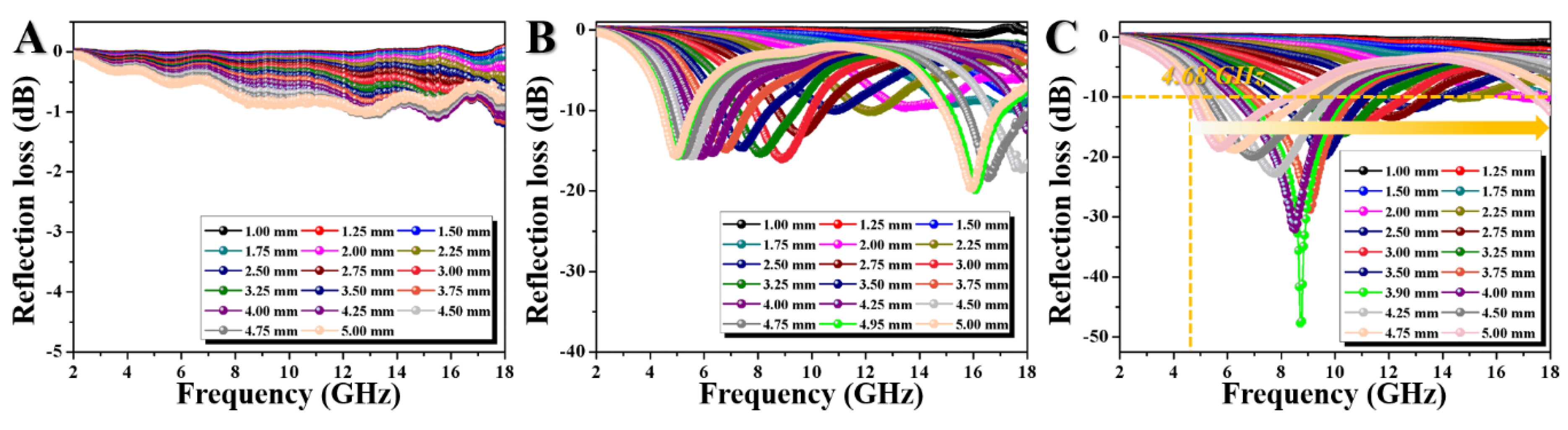
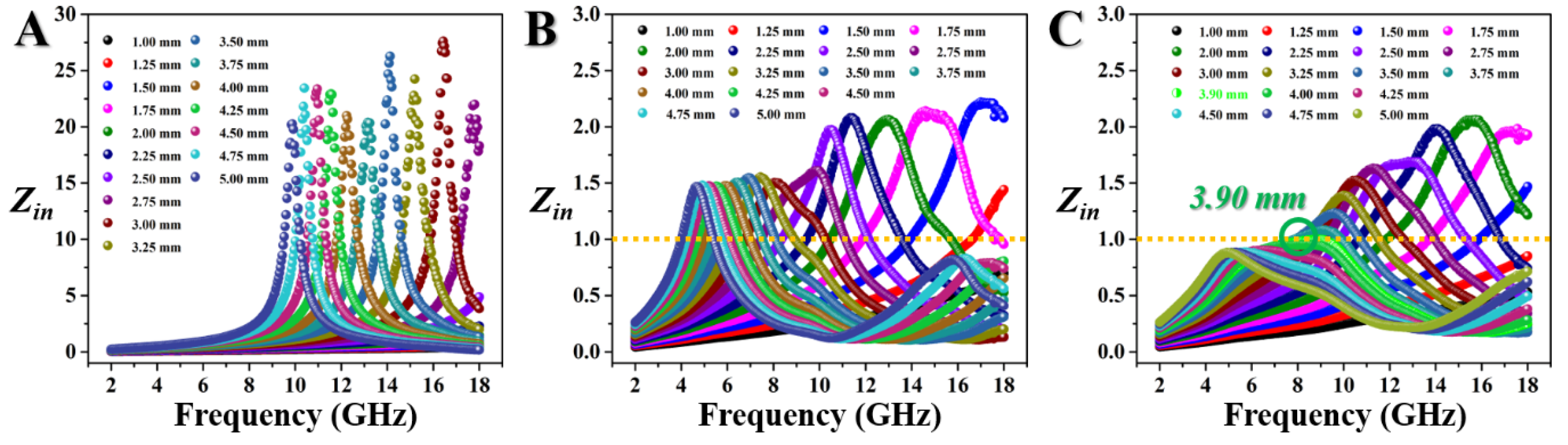
3.3. Electromagnetic Wave Absorption Capacities of the Samples

The curves for the responding EMW loss (RL) values of MF, CMF and MCMF are shown in Figure 8. MF presents no effective absorption performance ( | R L | < 10   dB ), and the minimum RL of CMF is only −19.85 dB at 16.08 GHz with a matching thickness of 4.95 mm, while MCMF displays the most excellent EMW absorption behavior with a minimum RL of −47.69 dB at 8.72 GHz with a matching thickness of 3.90 mm. Besides, the effective absorption frequency bandwidth is as large as 13.32 GHz from 4.68 to 18.00 GHz when adjusting the coating thickness. This excellent EMW absorption capacity is attributed to the superior electromagnetic properties (Figure 5A,B,D,E), electromagnetic matching effect (Figure 5C,F) and interfacial polarization effect (Figure 7).
In spite of the magnetic loss capacity being relatively lower than the dielectric loss capacity, the dielectric–magnetic synergistic effect should be considered for the excellent EMW absorption behavior of MCMF based on the fact that both the obtained dielectric phases and the magnetic phases understandably play non-negligible roles. As we know, hysteresis loss, residual loss and eddy current loss are normally the main loss approaches when magnetic loss processes happen [41]. Among these three effects, hysteresis loss should be considered according to the formation of Fe3O4, which is the typical ferromagnet phase in MCMF. Residual loss, which is supposed to consist of dimension resonance, exchange resonance and nature resonance when the frequency is larger than 2 GHz, is caused by the relaxation behaviors during the magnetization process [42]. If the absorber thickness (d) should be equal to an integral multiple of half wavelength (λ) based on the half wavelength formula as below:
d = n λ / 2   ( n = 1 , 2 , 3 , )
the residual loss mainly comes from dimension resonance. The corresponding wavelength of the EMW penetrating MCMF is determined by the following Equation (7), and shown in Figure 9A:
λ = c / 2 f ε μ
According to Figure 9A, 3.60 mm is the only suitable thickness for the absorber. The corresponding calculated frequency obtained in Figure 9A is 17.4 GHz. This value is far from the practical matching frequency (9.36 GHz) as shown in Figure 9B, indicating that the dimension resonance should also be excluded for the EMW absorption behavior of MCMF.
Additionally, nature resonance is proved to be present according to three observed resonant peaks in the μ curves of MCMF in Figure 5E. Furthermore, exchange resonance should also be considered since it generally occurs at this relatively high frequency from 2 to 18 GHz. The C0 value is calculated according to the following Equation (8) [43]:
C 0 = μ ( μ ) 2 f 1
to evaluate the effect of eddy currents on the magnetic loss. It is well known that if the C0 values remain constant from 2 to 18 GHz, the eddy current loss is the only reason for the magnetic loss. The calculated C0 is shown to vary with the frequency in Figure 9C, indicating the exclusion of the eddy-current-loss effect. Besides, the attenuation constant α is introduced into the attenuation abilities of the three absorbers (MF, CMF and MCMF) according to the following Equation (9):
α = 2 π f c × ( μ ε μ ε ) + ( μ ε μ ε ) 2 + ( μ ε + μ ε ) 2
The calculated α values of the absorbers are shown in Figure 9D, where MCMF shows the largest α value of 170.26 at 17.68 GHz, indicating that its largest attenuation capacity induces the corresponding strongest EMW absorbing performance.
The impedance difference between the air and the absorbers is explored to explain the trends of the α values according to the transmission line theory as in Equation (1). A well-matched impedance for the EMW absorbers is obtained when the Zin value is 1. As a result, no EMW reflection happens at the interfaces between the air and absorber. The calculated Zin values of the MF, CMF and MCMF are shown in Figure 10A–C respectively. Among these three absorbers, MCMF shows the optimal impedance matching with minimum reflection of the incident EMW at the interface between the air and absorber. The Zin value of MCMF with a thickness of 3.90 mm is very close to 1, indicating that the obtained most excellent EMW absorption behavior among the same type of absorbers [44,45,46,47] is attributed to the optimal dielectric–magnetic coupling in MCMF composites [48].

4. Conclusions

Herein, ultralight magnetic graphite-like C3N4/carbon foam (MCMF) with porous architectures was fabricated via impregnating the polymerized MF foams in Fe3O4 nanoparticle solution, followed by in situ pyrolysis at 1000 °C. MCMF was proved to possess a solid 3D-foam architecture consisting of interconnected cells and smooth skeletons, with graphitic C3N4/carbon and CFe15.1.α-Fe, Fe3O4 and Fe3C formed on the skeleton surface. The EMW absorption capacity of MCMF is better than that of the carbonized MF foam without Fe3O4 (CMF), and it exhibits excellent absorption behavior, with a minimum RL value of −47.38 dB, a relatively thin matching thickness of 3.90 mm and the broadest effective absorbing bandwidth of 13.32 GHz. MWS polarization and the residual loss were proved to be beneficial for such superior absorption behavior. Besides, graphitic C3N4 enriches the interface polarization effect and the electromagnetic matching effect. The microporous structures are beneficial for increasing EMW propagation, resulting in internal multiple reflections and scatterings, which are also beneficial for EMW attenuation.

Author Contributions

Y.Z. (Yihan Zhao) performed all the material preparation experiments and wrote the manuscript with the help of Y.Z. (Yao Zhang); R.L. and Z.W. performed the characterization of the materials and analyzed the results. Z.L. and Y.L. conceived and designed the experiment. All the authors contributed to the general discussion. All authors have read and agreed to the published version of the manuscript.

Funding

Financial support from the National Natural Science Foundation of China (No. 61601227, 31570552), China Postdoctoral Science Foundation (2017M621598), Nature Science Foundation of Jiangsu Province (BK20160939), Natural Science Foundation of the Jiangsu Higher Education Institutions of China (16KJB180010), Key University Science Research Project of Jiangsu Province (17KJA220004), Priority Academic Program Development of Jiangsu Higher Education Institutions (PAPD), and Student Practice Innovation and Training Program of Jiangsu Province (201710298017Z).

Conflicts of Interest

The authors declare no conflict of interest.

References

  1. Lv, H.; Yang, Z.; Ong, S.J.H.; Wei, C.; Liao, H.; Xi, S.; Du, Y.; Ji, G.; Xu, Z.J. A flexible microwave shield with tunable frequency-transmission and electromagnetic compatibility. Adv. Funct. Mater. 2019, 29, 1900163. [Google Scholar] [CrossRef]
  2. Wu, G.; Cheng, Y.; Yang, Z.; Jia, Z.; Wu, H.; Yang, L.; Li, H.; Guo, P.; Lv, H. Design of carbon sphere/magnetic quantum dots with tunable phase compositions and boost dielectric loss behavior. Chem. Eng. J. 2018, 333, 519–528. [Google Scholar] [CrossRef]
  3. Okoniewski, M.; Stuchly, M.A. A study of the handset antenna and human body interaction. IEEE Trans. Microw. Theory Tech. 1996, 44, 1855–1864. [Google Scholar] [CrossRef]
  4. Hirata, A.; Matsuyama, S.; Shiozawa, T. Temperature rises in the human eye exposed to EM waves in the frequency range 0.6-6 GHz. IEEE Trans. Electromagn. Compat. 2000, 42, 386–393. [Google Scholar] [CrossRef]
  5. Lou, Z.; Sun, J.; Lu, H.; Cai, J.; Zou, J.; Li, X.; Sun, Z.; He, H. Fabrication of magnetic wood and its magnetic and electromagnetic wave absorption properties. J. For. Eng. 2017, 2, 24–29. [Google Scholar] [CrossRef]
  6. Quan, B.; Gu, W.; Chen, J.; Xu, G.; Ji, G. Integrating carbonyl iron with sponge to enable lightweight and dual-frequency absorption. Nanotechnology 2019, 30, 195703. [Google Scholar] [CrossRef]
  7. Lv, H.; Ji, G.; Liang, X.; Zhang, H.; Du, Y. A novel rod-like MnO2 @Fe loading on graphene giving excellent electromagnetic absorption properties. J. Mater. Chem. C 2015, 3, 5056–5064. [Google Scholar] [CrossRef]
  8. Dong, F.; Zhao, Z.; Sun, Y.; Zhang, Y.; Yan, S.; Wu, Z. An advanced Semimetal–Organic Bi Spheres–g-C3N4 nanohybrid with SPR-Enhanced Visible-Light photocatalytic performance for NO purification. Environ. Sci. Technol. 2015, 49, 12432–12440. [Google Scholar] [CrossRef]
  9. Zheng, Y.; Liu, J.; Liang, J.; Jaroniec, M.; Qiao, S.Z. Graphitic carbon nitride materials: Controllable synthesis and applications in fuel cells and photocatalysis. Energy Environ. Sci. 2012, 5, 6717. [Google Scholar] [CrossRef]
  10. Park, S.S.; Chu, S.-W.; Xue, C.; Zhao, D.; Ha, C.-S. Facile synthesis of mesoporous carbon nitrides using the incipient wetness method and the application as hydrogen adsorbent. J. Mater. Chem. 2011, 21, 10801. [Google Scholar] [CrossRef]
  11. Li, Q.; Yang, J.; Feng, D.; Wu, Z.; Wu, Q.; Park, S.S.; Ha, C.-S.; Zhao, D. Facile synthesis of porous carbon nitride spheres with hierarchical three-dimensional mesostructures for CO2 capture. Nano Res. 2010, 3, 632–642. [Google Scholar] [CrossRef] [Green Version]
  12. Rashid, J.; Parveen, N.; Iqbal, A.; Awan, S.U.; Iqbal, N.; Talib, S.H.; Hussain, N.; Akram, B.; Ulhaq, A.; Ahmed, B.; et al. Facile synthesis of g-C3N4(0.94)/CeO2(0.05)/Fe3O4(0.01) nanosheets for DFT supported visible photocatalysis of 2-Chlorophenol. Sci. Rep. 2019, 9, 10202. [Google Scholar] [CrossRef] [PubMed] [Green Version]
  13. Zheng, Y.; Jiao, Y.; Chen, J.; Liu, J.; Liang, J.; Du, A.; Zhang, W.; Zhu, Z.; Smith, S.C.; Jaroniec, M.; et al. Nanoporous Graphitic-C3N4@Carbon Metal-Free Electrocatalysts for Highly Efficient Oxygen Reduction. J. Am. Chem. Soc. 2011, 133, 20116–20119. [Google Scholar] [CrossRef] [PubMed]
  14. Quan, B.; Liang, X.; Xu, G.; Cheng, Y.; Zhang, Y.; Liu, W.; Ji, G.; Du, Y. A permittivity regulating strategy to achieve high-performance electromagnetic wave absorbers with compatibility of impedance matching and energy conservation. New J. Chem. 2017, 41, 1259–1266. [Google Scholar] [CrossRef]
  15. Lv, H.; Ji, G.; Liu, W.; Zhang, H.; Du, Y. Achieving hierarchical hollow carbon@Fe@Fe3O4 nanospheres with superior microwave absorption properties and lightweight features. J. Mater. Chem. C 2015, 3, 10232–10241. [Google Scholar] [CrossRef]
  16. Bregar, V.B. Advantages of ferromagnetic nanoparticle composites in microwave absorbers. IEEE Trans. Magn. 2004, 40, 1679–1684. [Google Scholar] [CrossRef]
  17. Liu, J.; Liu, Y.; Liu, N.; Han, Y.; Zhang, X.; Huang, H.; Lifshitz, Y.; Lee, S.-T.; Zhong, J.; Kang, Z. Metal-free efficient photocatalyst for stable visible water splitting via a two-electron pathway. Science 2015, 347, 970–974. [Google Scholar] [CrossRef]
  18. Wang, Y.; Wang, X.; Antonietti, M. Polymeric Graphitic Carbon Nitride as a Heterogeneous Organocatalyst: From Photochemistry to Multipurpose Catalysis to Sustainable Chemistry. Angew. Chem. Int. Ed. 2012, 51, 68–89. [Google Scholar] [CrossRef]
  19. Chen, Y.-J.; Xiao, G.; Wang, T.-S.; Ouyang, Q.-Y.; Qi, L.-H.; Ma, Y.; Gao, P.; Zhu, C.-L.; Cao, M.-S.; Jin, H.-B. Porous Fe3O4/Carbon Core/Shell Nanorods: Synthesis and electromagnetic properties. J. Phys. Chem. C 2011, 115, 13603–13608. [Google Scholar] [CrossRef]
  20. Lou, Z.; Li, Y.; Han, H.; Ma, H.; Wang, L.; Cai, J.; Yang, L.; Yuan, C.; Zou, J. Synthesis of porous 3D Fe/C composites from waste wood with tunable and excellent electromagnetic wave absorption performance. ACS Sustain. Chem. Eng. 2018, 6, 15598–15607. [Google Scholar] [CrossRef]
  21. Lou, Z.; Yuan, C.; Zhang, Y.; Li, Y.; Cai, J.; Yang, L.; Wang, W.; Han, H.; Zou, J. Synthesis of porous carbon matrix with inlaid Fe3C/Fe3O4 micro-particles as an effective electromagnetic wave absorber from natural wood shavings. J. Alloys Compd. 2019, 775, 800–809. [Google Scholar] [CrossRef]
  22. Liu, Q.; Liu, X.; Feng, H.; Shui, H.; Yu, R. Metal organic framework-derived Fe/carbon porous composite with low Fe content for lightweight and highly efficient electromagnetic wave absorber. Chem. Eng. J. 2017, 314, 320–327. [Google Scholar] [CrossRef]
  23. Li, Y.; Mao, Z.; Liu, R.; Zhao, X.; Zhang, Y.; Qin, G.; Zhang, X. Ultralight Fe@C Nanocapsules/Sponge composite with reversibly tunable microwave absorption performances. Nanotechnology 2017, 28, 325702. [Google Scholar] [CrossRef] [PubMed]
  24. Zhang, X.-J.; Wang, G.-S.; Cao, W.-Q.; Wei, Y.-Z.; Liang, J.-F.; Guo, L.; Cao, M.-S. Enhanced Microwave absorption property of reduced graphene oxide (RGO)-MnFe2O4 nanocomposites and polyvinylidene fluoride. ACS Appl. Mater. Interfaces 2014, 6, 7471–7478. [Google Scholar] [CrossRef] [PubMed]
  25. Yan, L.; Wang, J.; Han, X.; Ren, Y.; Liu, Q.; Li, F. Enhanced microwave absorption of Fe nanoflakes after coating with SiO2 nanoshell. Nanotechnology 2010, 21, 095708. [Google Scholar] [CrossRef]
  26. Qiao, M.; Lei, X.; Ma, Y.; Tian, L.; Wang, W.; Su, K.; Zhang, Q. Facile synthesis and enhanced electromagnetic microwave absorption performance for porous core-shell Fe3O4@MnO2 composite microspheres with lightweight feature. J. Alloys Compd. 2017, 693, 432–439. [Google Scholar] [CrossRef]
  27. Sun, D.; Zou, Q.; Wang, Y.; Wang, Y.; Jiang, W.; Li, F. Controllable synthesis of porous Fe3O4@ZnO sphere decorated graphene for extraordinary electromagnetic wave absorption. Nanoscale 2014, 6, 6557–6562. [Google Scholar] [CrossRef]
  28. Qiang, R.; Du, Y.; Zhao, H.; Wang, Y.; Tian, C.; Li, Z.; Han, X.; Xu, P. Metal organic framework-derived Fe/C nanocubes toward efficient microwave absorption. J. Mater. Chem. A 2015, 3, 13426–13434. [Google Scholar] [CrossRef]
  29. Halvarsson, S.; Edlund, H.; Norgren, M. Properties of medium-density fibreboard (MDF) based on wheat straw and melamine modified urea formaldehyde (UMF) resin. Ind. Crops Prod. 2008, 28, 37–46. [Google Scholar] [CrossRef]
  30. Ma, Y.; Zhang, W.; Wang, C.; Xu, Y.; Li, S.; Chu, F. Preparation and characterization of melamine modified urea-formaldehyde foam. IPP 2013, 28, 188–198. [Google Scholar] [CrossRef]
  31. Lv, H.; Zhang, H.; Zhao, J.; Ji, G.; Du, Y. Achieving excellent bandwidth absorption by a mirror growth process of magnetic porous polyhedron structures. Nano Res. 2016, 9, 1813–1822. [Google Scholar] [CrossRef]
  32. Pei, W.; Shang, W.; Liang, C.; Jiang, X.; Huang, C.; Yong, Q. Using lignin as the precursor to synthesize Fe3O4@lignin composite for preparing electromagnetic wave absorbing lignin-phenol-formaldehyde adhesive. Ind. Crop Prod. 2020, 154, 112638. [Google Scholar] [CrossRef]
  33. Yan, S.C.; Li, Z.S.; Zou, Z.G. Photodegradation Performance of g-C3N4 Fabricated by Directly Heating Melamine. Langmuir 2009, 25, 10397–10401. [Google Scholar] [CrossRef] [PubMed]
  34. Lou, Z.C.; Wang, W.K.; Yuan, C.L.; Zhang, Y.; Li, Y.J.; Yang, L.T. Fabrication of Fe/C composites as effective electromagnetic wave absorber by carbonization of pre-magnetized natural wood fibers. J. Bioresour. Bioprod. 2019, 4, 43–50. [Google Scholar]
  35. Liu, B.; Yao, H.; Daniels, R.A.; Song, W.; Zheng, H.; Jin, L.; Suib, S.L.; He, J. A facile synthesis of Fe3C@mesoporous carbon nitride nanospheres with superior electrocatalytic activity. Nanoscale 2016, 8, 5441–5445. [Google Scholar] [CrossRef]
  36. Guo, Q.; Teng, X.; Rahman, S.; Yang, H. Patterned Langmuir−Blodgett Films of Monodisperse Nanoparticles of Iron Oxide Using Soft Lithography. J. Am. Chem. Soc. 2003, 125, 630–631. [Google Scholar] [CrossRef]
  37. Tan, L.; Xu, J.; Zhang, X.; Hang, Z.; Jia, Y.; Wang, S. Synthesis of g-C3N4/CeO2 nanocomposites with improved catalytic activity on the thermal decomposition of ammonium perchlorate. Appl. Surf. Sci. 2015, 356, 447–453. [Google Scholar] [CrossRef]
  38. Xue, B.; Fang, L.Y.; Liang, C.; Li, X.; Lai, C.H.; Yong, Q.; Huang, C.X. Preparation of lignin/Fe3O4 based magnetic material and their performance in adsorption of dyes. J. For. Eng. 2019, 4, 85–92. [Google Scholar] [CrossRef]
  39. Dong, X.L.; Zhang, X.F.; Huang, H.; Zuo, F. Enhanced microwave absorption in Ni/polyaniline nanocomposites by dual dielectric relaxations. Appl. Phys. Lett. 2008, 92, 013127. [Google Scholar] [CrossRef]
  40. Quan, B.; Liang, X.; Ji, G.; Cheng, Y.; Liu, W.; Ma, J.; Zhang, Y.; Li, D.; Xu, G. Dielectric polarization in electromagnetic wave absorption: Review and perspective. J. Alloys Compd. 2017, 728, 1065–1075. [Google Scholar] [CrossRef]
  41. Quan, B.; Liang, X.; Ji, G.; Zhang, Y.; Xu, G.; Du, Y. Cross-Linking-Derived Synthesis of Porous CoxNiy/C Nanocomposites for Excellent Electromagnetic Behaviors. ACS Appl. Mater. Interfaces 2017, 9, 38814–38823. [Google Scholar] [CrossRef] [PubMed]
  42. Lou, Z.; Han, H.; Yang, L.; Zhou, M.; Cai, J.; Zou, J.; Sun, Z. Preparation of multi-layer magnetic board, and its electromagnetic wave shielding properties. J. For. Eng. 2018, 3, 25–31. [Google Scholar] [CrossRef]
  43. Mattsson, M.S.; Niklasson, G.A.; Forsgren, K.; Hårsta, A. A frequency response and transient current study of β-Ta2O5: Methods of estimating the dielectric constant, direct current conductivity, and ion mobility. J. Appl. Phys. 1999, 85, 2185–2191. [Google Scholar] [CrossRef]
  44. Wang, X.Y.; Lu, Y.K.; Zhu, T.; Chang, S.C.; Wang, W. CoFe2O4/N-doped reduced graphene oxide aerogels for high-performance microwave absorption. Chem. Eng. J. 2020, 388, 124317. [Google Scholar] [CrossRef]
  45. Zhang, C.W.; Peng, Y.; Song, Y.; Li, J.J.; Yin, F.X.; Yuan, Y. Periodic three-dimensional nitrogen-doped mesoporous carbon spheres embedded with co/co3o4 nanoparticles toward microwave absorption. ACS Appl. Mater. Interfaces 2020, 12, 24102–24111. [Google Scholar] [CrossRef] [PubMed]
  46. Zhao, Z.H.; Kou, K.C.; Wu, H.J. 2-Methylimidazole-mediated hierarchical Co3O4/N-doped carbon/short-carbon-fiber composite as high-performance electromagnetic wave absorber. J. Colloid Interface Sci. 2020, 574, 1–10. [Google Scholar] [CrossRef] [PubMed]
  47. Niu, Y.C.; Li, X.A.; Dong, W.Q.; Zhang, C.; Zhao, K.H.; Wang, F.Y.; Wang, H.Y. Synthesis of N-doped carbon with embedded Fe/Fe3C particles for microwave absorption. J. Mater. Sci. 2020, 55, 11970–11983. [Google Scholar] [CrossRef]
  48. Lou, Z.; Han, H.; Zhou, M.; Han, J.; Cai, J.; Huang, C.; Zou, J.; Zhou, X.; Zhou, H.; Sun, Z. Synthesis of magnetic wood with excellent and tunable electromagnetic wave-absorbing properties by a facile vacuum/pressure impregnation method. ACS Sustain. Chem. Eng. 2018, 6, 1000–1008. [Google Scholar] [CrossRef]
Figure 1. (A) Schematic of magnetic graphite-like C3N4/carbon foam (MCMF) preparation. (B) TEM image of Fe3O4 nanoparticles. (C) Physical images of elasticity test. (D) SEM image of carbonized melamine formaldehyde (MF) foam without Fe3O4 (CMF) along with the C, O, N and Fe elemental EDS mapping images. (E) Practical image of MCMF. (F) SEM images of MCMF along with the corresponding C, O, N and Fe elemental EDS mapping images.
Crystals 10 00656 g001
Figure 2. XRD curves of magnetic MF foam (MMF) (black) and MCMF (green), respectively.
Crystals 10 00656 g002
Figure 3. XPS spectra of CMF and MCMF (A) along with corresponding high-resolution XPS spectra of C1s, Fe2p and N1s (BD), respectively.
Crystals 10 00656 g003
Figure 4. VSM curve of MCMF.
Crystals 10 00656 g004
Figure 5. Dielectric (AC) and magnetic (DF) parameters of MF, CMF and MCMF, respectively.
Crystals 10 00656 g005
Figure 6. Comparison of electrical conductivity of MF, CMF and MCMF.
Crystals 10 00656 g006
Figure 7. (A) Survey of the plots of ε vs. ε for MF, CMF and MCMF. Typical Cole–Cole semicircles of (B) MF, (C) CMF and (D) MCMF.
Crystals 10 00656 g007
Figure 8. The curves for the responding EMW loss (RL) values of (A) MF, (B) CMF and (C) MCMF.
Crystals 10 00656 g008
Figure 9. (A) Frequency dependence of microwave transmission in MCMF. The inset shows a photograph of the thickness for MCMF/paraffin composites using a Vernier caliper. (B) Reflection loss value of MCMF at 3.24 mm. The (C) C0 and (D) α values of the three absorbers.
Crystals 10 00656 g009
Figure 10. The calculated Zin values for (A) MF, (B) CMF and (C) MCMF.
Crystals 10 00656 g010

