An Experimental and Theoretical Study of Wave Damping due to the Elastic Coating of the Sea Surface


1
Department of Marine Environment and Engineering, National Sun Yat-Sen University, Kaoshiung 804, Taiwan
2
Laboratory of shelf and sea coasts, Shirshov Institute of Oceanology, Russian Academy of Sciences, Moscow 117997, Russia
3
Department of Hydraulic and Ocean Engineering, National Cheng Kung University, Tainan 701, Taiwan
*
Author to whom correspondence should be addressed.
J. Mar. Sci. Eng. 2020, 8(8), 571; https://doi.org/10.3390/jmse8080571
Submission received: 15 June 2020
/
Revised: 25 July 2020
/
Accepted: 27 July 2020
/
Published: 29 July 2020
(This article belongs to the Special Issue Waves and Ocean Structures)
Abstract
:Flexible plates or membranes located on the sea surface can be effective for attenuation waves approaching the beach. The most efficient structures should be found through comprehensive research using developed experiments and theory. Our experimental work was focused on the wave propagation and attenuation passing through floating elastic structures. The experiments were conducted at the wave flume of Tainan Hydraulics Laboratory, National Cheng Kung University, Taiwan. The experiment mainly analyzes the reflection coefficient, transmission coefficient and energy loss of the regular wave of intermediate water depth after passing through the elastic structure under different wave steepness and other different wave conditions. Our experiments also explore the comparison of energy dissipation effects and the differences in motion characteristics between different elastic plates and different plate fixing methods. Three elastic materials were tested in the experiments: Latex, cool cotton and polyvinyl chloride (PVC). A model of a thin elastic plate covering the sea surface was used to evaluate the effectiveness of the structure of the wave barrier. The results of experiments carried out in the wave flume were compared with theoretical predictions in a wide range of generated waves.
1. Introduction
Taiwan is densely populated and surrounded by the sea. Not only the continuous development of inland lands, but also the development of areas around the coast is quite frequent. Therefore, how to protect yourself from coastal erosion and other natural disasters has always been the subject of the efforts of scientists and experts in coastal engineering. However, traditional protection methods mainly use rigid structures such as breakwaters, sea embankments and jetty to protect the coast, block water flow, prevent seawater intrusion and land loss.
However, such rigid construction methods can cause problems such as increased reflection and premature erosion or structural damage, and can even cut off sand downstream drift and cause loss on the beach.
Consequently, the use of coastal space and coastal hydrophilicity has also become one of development considerations. Widely proposed new methods and concepts, mainly based on the idea of not harming the beach area. Even in addition to protecting the coast, they can also serve as ecological services to the landscape while relaxing. Therefore, in recent years, flexible construction methods have gradually replaced rigid construction methods and become a tendency to protect the coast. In flexible construction methods, various construction methods have their own characteristics and effects. Among them, the design of highly adaptable floating breakwater is widely used in marine engineering, because various types of breakwaters may have different interactions with waves to achieve the effect of energy dissipation. Therefore, various floating structures are constantly being proposed and discussed.
There are many relevant literatures about different floating structures. Theoretical analysis of the transmission coefficient of incoming waves after passing through a fixed plate and a floating plate is performed in [1]. The main result is that the value of the transmission coefficient is mainly affected by the obtained wavelength. The transition and reflection of waves interacting with floating or submerging objects causing radiation problems in two or three directions of fluctuation was under discussion in [2,3].
A -type floating breakwater was first introduced in [4]. An extremely simple formula is proposed for the transmittance, which depends only on the length of the incoming wave, the geometry of the breakwater, and the depth of the water. The model underestimates the transmission of short waves and overestimates the transmission of long waves, but at the same time, the model was a good starting point for further research and improvement. A number of works are devoted to the further development of a -type floating breakwater—a review and new approaches are presented in [5]. There are still many problems for analysis: Complex hydrodynamics with vortices and turbulence, a variety of mooring systems, scaling issues, etc.
The reflection and transmission of waves by submerged horizontal rigid plate was studied in [6,7]. It was shown, that plate can reflect significant amount of wave energy for specific wavelengths.
The transmittance of water waves passing through a floating plate was experimentally investigated in [8]. The authors concluded that when the length of the floating horizontal plane is several times the length of the incoming wave, the attenuation of the waves is stronger.
Experimental study of the transmission and reflection coefficient of waves of intermediate water depth through a lattice-shaped perforated horizontal plate was presented in [9]. The experimental results suggest that as the length and wavelength ratio of the structure and the steepness of the wave increase, the transmission coefficient decreases. It was also found that when the depth of the structure is increased, the reflection coefficient increases.
The effect of immersed or surface-mounted horizontal flexible membranes on the dynamics of waves was studied by the methods of linear hydro elastic theory in [10]. The numerical results for the reflection and attenuation of the incident waves were reasonably consistent with existing laboratory experiments.
A freely floating porous box was theoretically investigated in [11]. The small drift forces of the porous bodies gave the box an advantage for use as a floating breakwater.
The spar buoy floating breakwater is presented in [12]. An investigation into the wave reflection and transmission properties was carried out with a study on mooring tension induced by the waves.
A hydraulic model was used in [13] to study the transmission coefficient of waves after passing through floating structures with different properties and forms. It was found that the effect of installing a grid under the flat panel was the best, and showed that the steepness of the waves increased, and the transmission coefficient also decreased.
A new structure of a floating breakwater, consisting of several connected perforated diamond-shaped blocks, was proposed in [14]. It is experimentally shown that the proposed wave breaking system can dissipate the energy of the incoming wave more efficiently than already known. Possible mooring forces are discussed.
The interaction between the floating thin elastic plate and water surface waves was investigated in [15]. Authors suggested different oscillation modes of a two-phase structure in dependence of the elasticity properties and geometrical scales of the cover, characteristics of incoming waves and depth of fluid.
In this paper, the performance of an elastic thin plate floating breakwater is experimentally and theoretically examined. Wave transmission and attenuation in dependence of its steepness, elastic properties of the membrane, its length, and water depth are investigated. The theoretical model is constructed in the long wave approximation which is usually applicable in the beach zone of the Ocean for the relatively long and energetic incoming swell. We consider the case of fix edges of the elastic plate boundary conditions as the most effective configuration for transmitted wave suppression [7].
The structure of the article is as follows.
Section 2 describes the experimental setup. We present laboratory equipment and a detailed test configuration. There is a full and detailed description of the laboratory tank, measuring instruments, the characteristics of a set of elastic plates and the organization of the experiment itself.
Section 3 of this article presents experimental results. The reflection, transmittance and energy loss corresponding to different generated wave steepness, the ratios of the wave length and length of the plate are discussed. Corresponding reflections, transmittance and energy loss under different elastic plates are also analyzed.
2. Experimental Setup
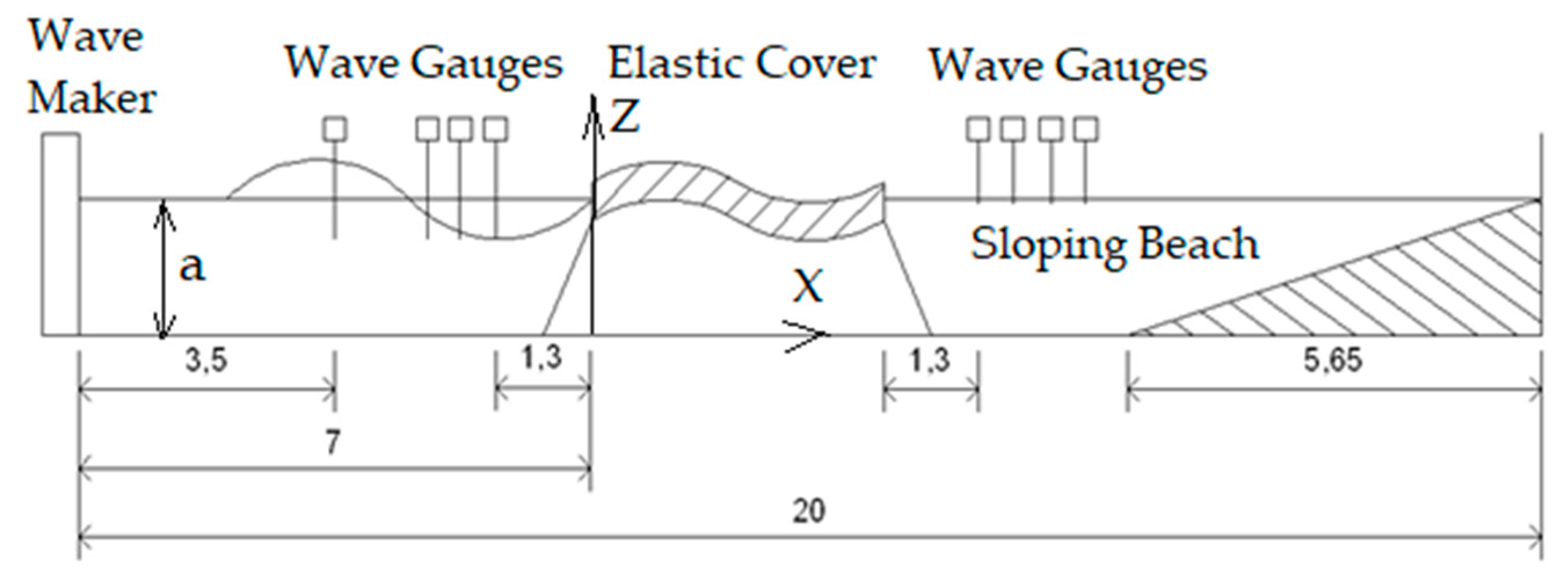
The experiments were carried out in a laboratory wave flume (Figure 1) located in the Tainan Hydraulics Laboratory (THL), National Cheng Kung University (NCKU), Taiwan. The dimensions of the flume are 0.5 m wide, 0.7 m deep and 20 m long.
It is mainly used to measure the attenuation height of the wave in the water tank after passing through the elastic membrane covering the water surface. Therefore, the equipment used is a test tank, wave maker, wave elimination section, elastic plate, CCD camera, wave gauges, power supply and signal amplifier. Both sides of the tank are laid with reinforced transparent glass to observe the movement in the flume. A flat push wave maker is set at the left end of the tank. A schematic representation of the experimental setup is shown in Figure 2. A piston-type wave maker was used, controlled by software developed in the Hydraulic Research Institute. This wave-making system can produce periodic regular waves, irregular waves and solitary waves. The regular wave range created by the experimental wave maker has period 0.65–1.45 s wave height 0–6 cm.
A sloping beach was constructed at the end of the wave flume, which can reduce the wave reflection to 5%. The wave-cutting section was a 1:11.7 acrylic slope, located at the other end of the tank. It is 0.48m high and 5.65m long. The bottom is supported by a steel frame to avoid deformation of the acrylic plate caused by wave water pressure and wave energy.
This experiment uses the capacitive wave gauges developed by the National Cheng Kung University Hydraulic Engineering Institute. The output signal is 0–5 V, the acquisition frequency can reach 50 Hz, and the wave height measurement accuracy is ±0.5 mm.
A total of eight capacitive wave gauges were used in this test. The first wave gauge was placed at a distance of 3.5 m from the wave generator to check the incident wave height. The second, third, and fourth wave gauges are placed at the front of the plate used to measure and analyze the height of incoming and reflected waves. The height of the fifth wave probe is 1.3 m behind the plate, used to measure transmission wave height and attenuation after passing through the cover. The sixth, seventh and eighth wave gauges are in front of the wave-elimination band, and are used to observe the wave height after the transmission wave is stabilized, and the wave reflectivity of the wave-elimination band.
The shooting range of CCD camera is 25 cm × 25 cm. 1.2 m away from the tank. Shooting at 30 frames per second for 30 s. It is used to observe the movement of the plate and fluid.
Anchor has the four points on the front and rear ends of the membrane are provided with 10 kg iron pieces for fixing the components according to different fixing methods.
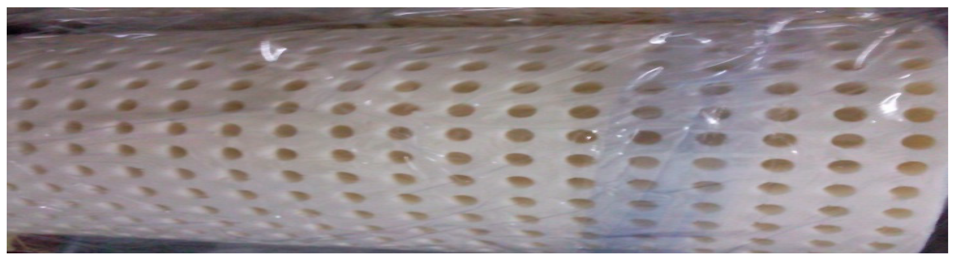
Three different elastic plates where tested. They are the latex membrane with better elasticity (Figure 3), the foam component with the second best elasticity (Figure 4) and a flat rigid plastic component—Figure 5 (Table 1).
In order to compare their efficiencies on attenuating surface waves under different wave and water depth conditions, monochromatic waves were generated in the range: the wave height is 2–6 cm, and the period is 0.65–1.45 s. The test conditions are as follows (see Table 1):
The characteristics of the generated waves with different time periods were determined from the dispersion relation for the intermediate water depth and are presented in Table 2, Table 3 and Table 4.
The test preparation was based on the following plan. The wave maker and signal amplifier was fully warmed up before the experiment to ensure the stability of the wave maker operation, and then the wave making and data collection can be performed according to the test conditions. The wave making time of each set of data is 45 s, the wave gauge records at 60 Hz per second for 60 s and the CCD camera shoots at 30 frames per second for 30 s. The interval of each test group is 10 min to ensure that the disturbance of the previous group of tests tends to be stable. After completing the entire set of tests to be carried out, the fixing method and the elastic plate can be replaced, and the above steps are repeated until all tests are complete.
Several methods of separation for incident and reflected waves exist [16,17,18]. The most common procedure is to install a number of wave gauges at relatively short distances from each other and to make the simultaneous measurements of the waves at all wave gauges. We used three wave gauges and the least squares method for separating incident and reflected waves [17]. The second, third and fourth wave gauges are placed at the front of the plate used to measure and analyze the height of incoming and reflected waves. The wave reflection coefficient and incident amplitude are estimated from wave heights measured at three fixed wave gauges with unequal spacing. The spacings between wave gauges must not be an integer that is a multiple of a half wave length. The optimal spacing between wave gauges is still under discussion [18].
The distance between the wave gauges on both sides of the structure must be at least three times the water depth to reduce the impact of dissipated waves. In this paper, the mature wave height after 15 s is taken as the analysis; and the blank test shows that the reflectivity of the elimination band is less than 0.1.
According to the theory of potential current, without energy loss, the ratio of the sum of the square of the transmitted wave height and the reflected wave height is 1, that is, the square of reflectance plus the square of transmittance:
Then the wave energy loss coefficient can be expressed as:
Then the wave energy loss coefficient can be regarded as the energy coefficient reduced by the action of the elastic plate body.
3. Experimental Results and Discussion
When the membrane is not fixed and the front end is fixed, the movement of the plate’s surge, sway, and heave is more intense than when the two ends are fixed, and the disturbance of the dissipation wave may have a greater impact on the test. Therefore, we were concentrated on the effect of wave steepness on reflection and transmission coefficients, energy loss coefficient and attenuation of the wave height when different elastic plates are used and both ends of the floating cover are fixed.
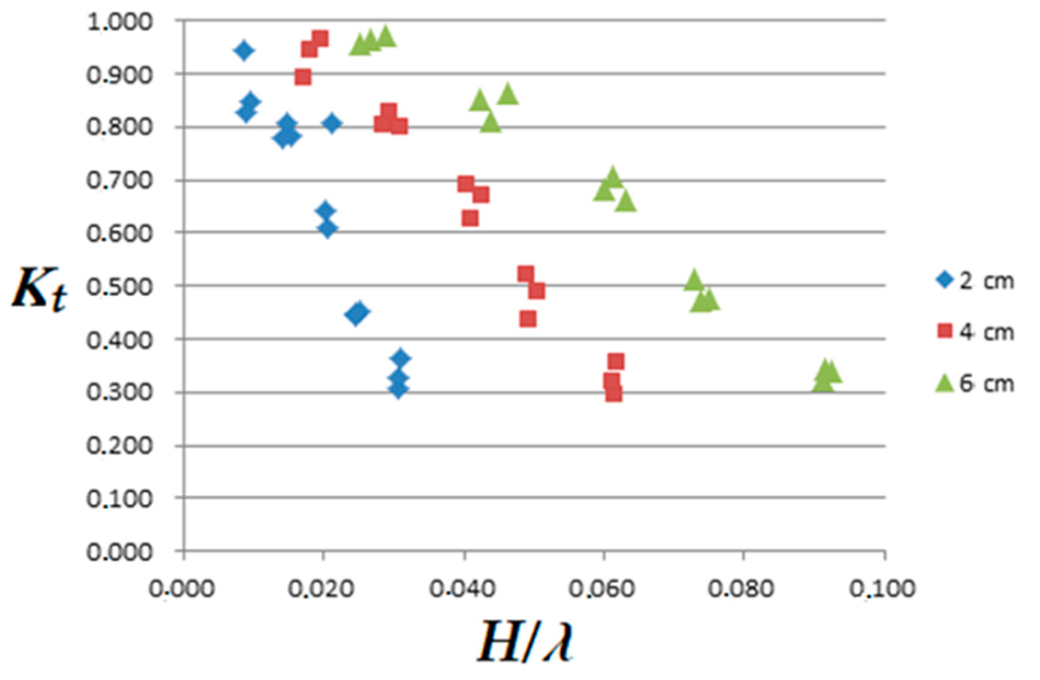
Figure 6 shows the transmission coefficient for latex plate and different steepness of the incoming wave, when the wave height is 2 cm, 4 cm and 6 cm. The graph clearly shows that for any wave height, the greater the steepness of the wave, the lower the transmission coefficient. From this figure, it can be seen that the elastic plate has a certain effect of reducing waves. However, when the wave steepness is very small, the transmission coefficient is close to 1 (that is, the wave is almost completely transmitted). Reflection coefficients of the latex plate are presented in Figure 7.
The graph shows that at different wave heights, the reflection coefficient has 1–2 peaks in the middle. The trend line is closer to the quadratic curve. It is speculated that this phenomenon is related to the period (wavelength) of the wave. That is, under different periods or wavelengths, the wave reflections caused by its components have different characteristics.
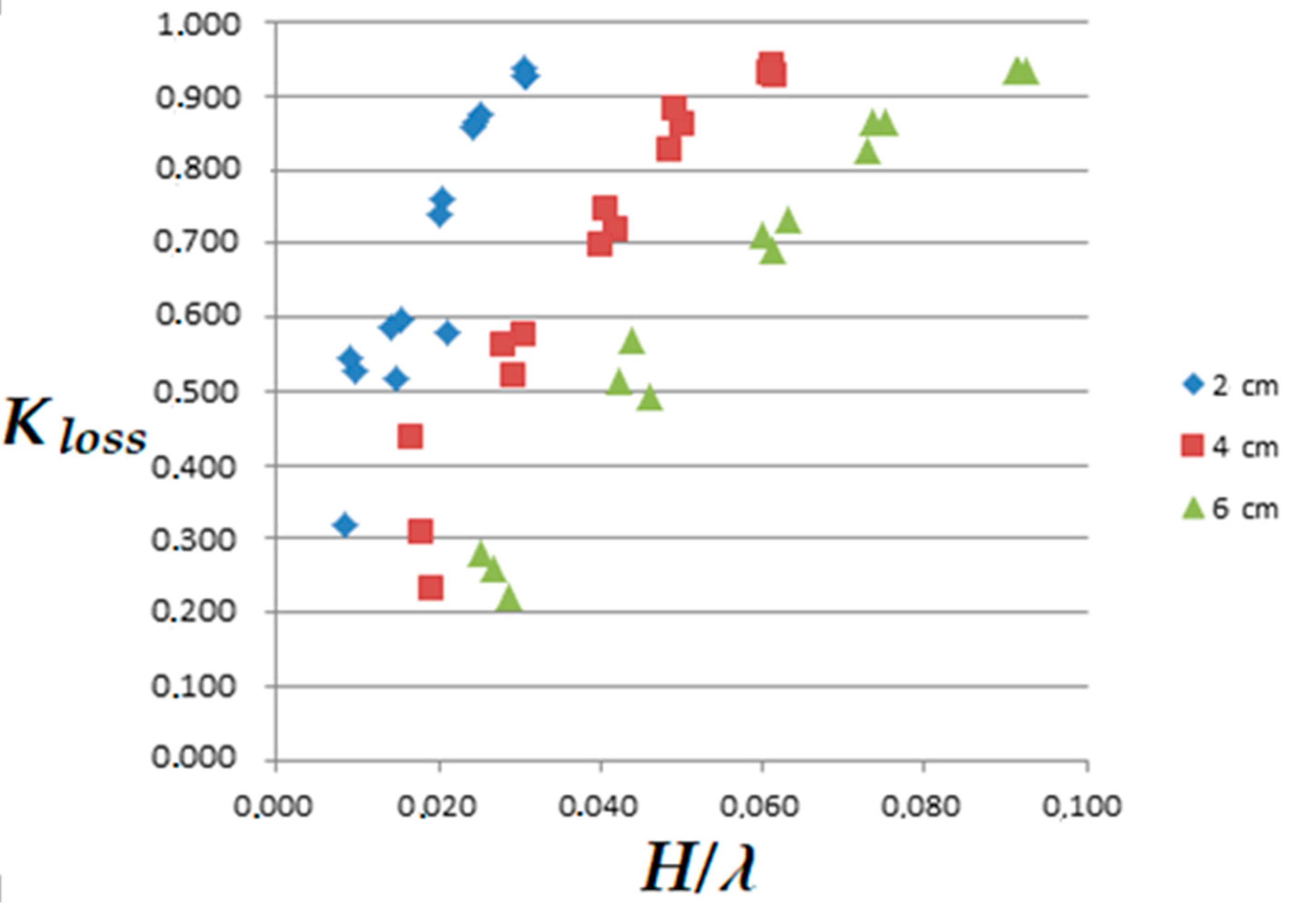
Figure 8 shows the energy loss (energy reduction) coefficients corresponding to different wave steepness when the wave height is 2 cm, 4 cm and 6 cm. First, it can be observed from the figure that when the steepness of the wave is very small (when the wavelength is longer), the trend of loss caused by the steepness change is not obvious. When the loss coefficient is greater than 0.5, the greater the steepness of the wave corresponds to a larger energy loss coefficient. Secondly, from this figure it can also be found that the energy dissipation effect of the elastic plate is significant, and the energy loss coefficient can reach about 0.9.
It can be seen from the above test results that the steepness of the wave has a significant effect on the interaction between the elastic plate and the wave, and it is also seen that the damping effect of the elastic membrane is strong. The period and wavelength should be the main parameters that affect the motion characteristics.
Next, we analyzed the properties of transmission and reflection of waves depending on the depth of water a, which are presented in Figure 9 and Figure 10.
It can be found that at different steepness of the waves, the transmission and reflection coefficients corresponding to different water depths do not differ much. The reason should be that all test conditions relate to the intermediate water depth, and the range of water depth changes has a smaller effect on this component than other parameters.
Figure 11 shows the relationship between the ratio of the plate length and the wavelength of the incident wave (L/λ) and the corresponding transmission coefficient. It can be seen that the greater the ratio (L/λ), the smaller the transmission coefficient, that is, the effect of energy dissipation is stronger.
When the wavelength of the incident wave is greater than the length of the plate, that is, the ratio (L/λ) is less than 1, the transmission coefficient is about 0.9, and the wave elimination effect is not effective.
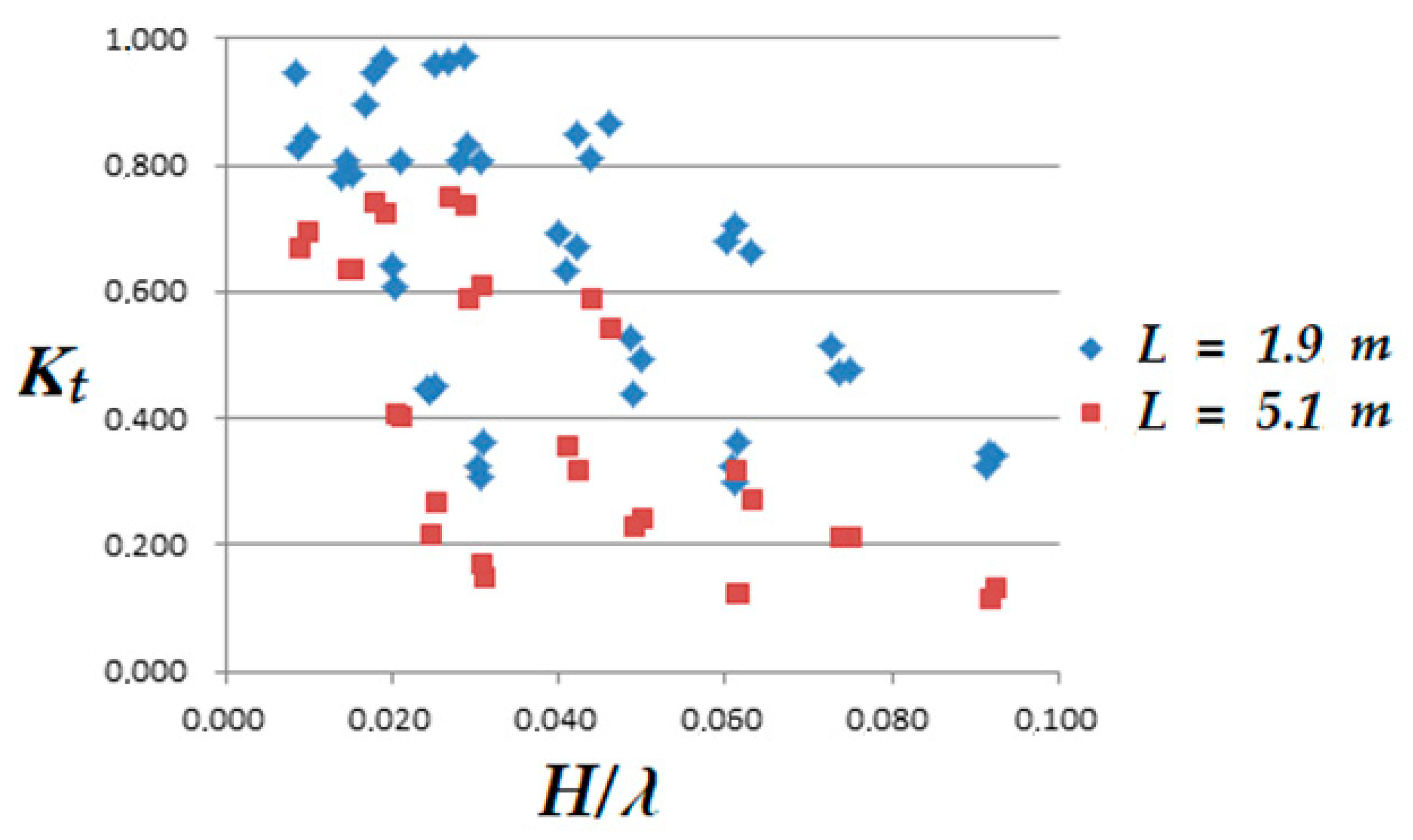
Figure 12 shows the transmittances corresponding to the steepness of the waves at different plate lengths. It can be clearly seen that under each wave condition, the transmission coefficient of the long plate is smaller than that of the short plate.
Different elastic plates may have different oscillation modes and different interactions with waves. Therefore, we analyzed the motion characteristics of regular waves acting on different elastic membrans (latex E = 0.01 gpa, foam E = 0.07 gpa and rigid member E = 3.5 gpa) when both ends are fixed.
Figure 13 shows the relationship between the wave steepness and transmission coefficient of different elastic plates when the wave height is 2, 4 and 6 cm at a fixed water depth 0.3 m. It shows that the transmission coefficient of the rigid plate is slightly lower than that of the other two more soft plates. The transmission coefficient of the foam pate is the largest.
4. Analytical Model
We consider two-dimensional interaction (2D) of a surface-mounted elastic plate of length L and a thickness with a monochromatic incident surface wave of height and wavelength . Orthogonal system of coordinate is chosen with X-axis directed horizontally and Z-axis directed upward (see Figure 2). We assume also an ideal incompressible fluid. Taking in mind that breakwaters should be located in coastal areas and effective ones should have a length comparable to the length of incoming waves, we consider the long wave approximation model: the characteristic wave length and the scale of the wave breaker L are much larger than the water depth a:
That is why we will use the linearized standard shallow water model for the open sea water :
where H = H(X,T) is the sea surface elevation, —depth integrated velocity of fluid, P, are pressure in fluid and atmospheric pressure, respectively, g is the gravity acceleration, —density of fluid.
The dynamics of the elastic membrane on the sea surface (0 < X < L) can be described within the thin elastic plate approximation model [19,20]:
where the terms in the left side of the equation express the external load acting on the surface of the plate in the transverse direction, P is the pressure in fluid on the internal plate surface , constant atmospheric pressure is assumed on the external plate surface ; is these Young modulus, ( = 0.3) is the Poisson coefficient and is the density of the plate material.
The fluid motion under the elastic membrane (0 < X < L) in the long wave approximation can be also described by the shallow water model:
The solutions of the Equations (3)–(5) in the regions X < 0, 0 < X < L, X > L should be connected by the mass and momentum conservation laws at the boundaries:
where superscripts (+) and (−) correspond to the limiting values of functions at the different sides of the boundary cross sections.
Boundary conditions for the elastic membrane oscillations include zero displacements and transverse forces at the edges of plate [19,20]:
We introduce dimensionless variables in the following form:
Then, the equations of the two-phase motion and corresponding boundary conditions (1)–(5) can be written in the dimensionless form
For
For
where
Boundary conditions for fluid (x = 0, x = 1)
Boundary conditions for elastic plate (x = 0, x = 1)
We will investigate solutions for transmitting and scattering by the flexible membrane of the initially monochromatic wave in the open water:
Dispersion relation for the elastic membrane oscillations can be found from the system of Equations (10) and (11):
Different modes of oscillations of the membrane around a constant level have the form:
Solution of Equation (15) defines six own modes of membrane oscillations on the water surface with frequency :
where
Boundary conditions (13) for the plate oscillations define four relationships for six wave amplitudes:
The other four relations for together with amplitudes for reflected and transmitted waves are followed from the boundary conditions (12):
5. Theoretical Results and Discussion
Floating plate wave barriers have been known and analyzed for decades [5]. Their basic properties are also well known: the length of the plate should be at least comparable to the length of the incoming waves in order to have some chance of suppressing their amplitude and, accordingly, be effective. Too long plates, several times longer than typical energy waves coming to the beach, are not practical and are not very suitable for use. The idea of this study is to consider floating elastic plates with lengths of the same order as the incoming waves. The elastic plate interacts with the surrounding water and has its own life—a set of natural modes of oscillation, depending on the bending stiffness, geometric dimensions, mooring, etc. Our modeling analysis of the coupled fluid-elastic plate system gives the dispersion relation (15) of oscillations of the coating plate, which is characterized by pair of dimensionless parameters and . The parameter determines the elasticity property of the plate and also depends on the length of the plate and its thickness. Another parameter defines the relative role of the depth of fluid on oscillation of the plate.
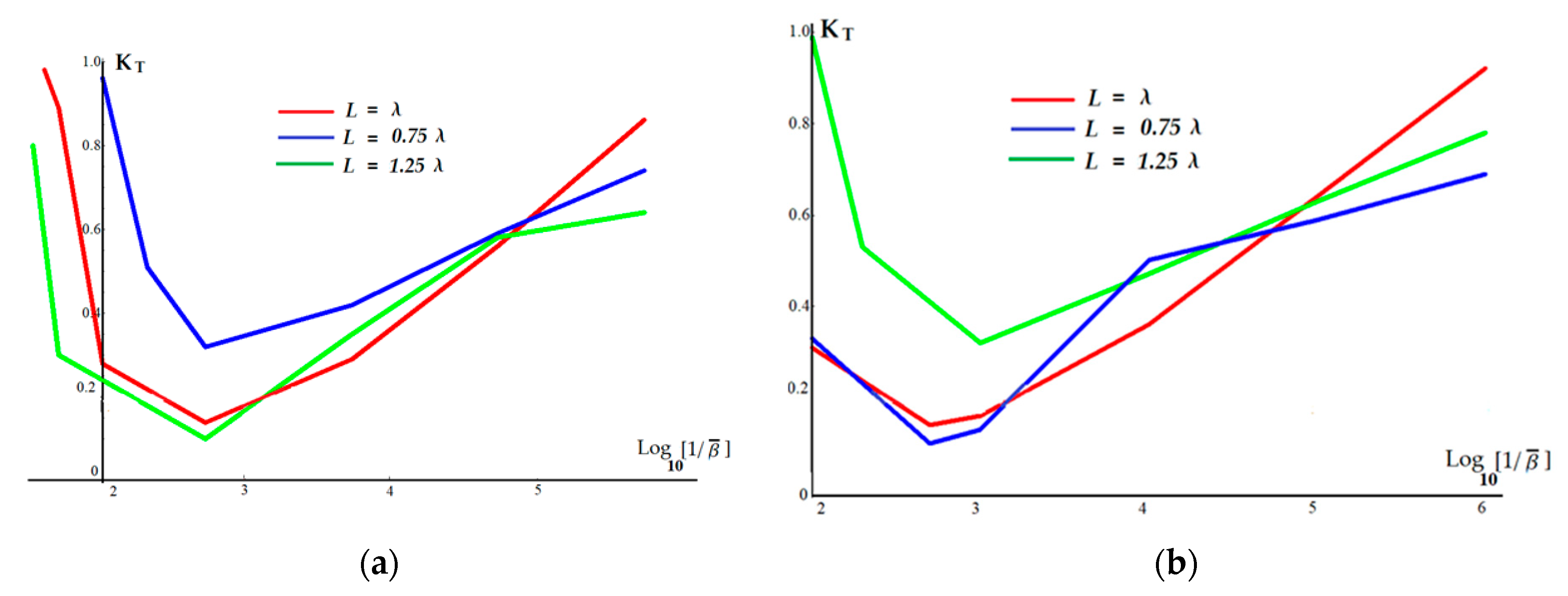
The main problem that we first analyzed was the following: can bending plate stiffness significantly affect the transmission characteristics of waves. We consider the most intriguing case when the length of incoming wave is not far away from length of the plate L = 1.9 m. The results of our numeral simulations are presented in Figure 14a. We fix all other parameters and so only the Young modulus was widely changed.
Results were quite surprising: dependence of wave transmittance is not monotonic—it has the same minimum for all considered range of waves: . Results of simulations for another length of plate L = 5.1 m are presented in Figure 14b. As one can see transmitting coefficient has the same minimum . Our experimental results qualitatively correspond to numerical simulations, but all they are in the region of high transmittance and so, not so interesting. The conclusion we made from our two simulations that probably not just specific elasticity itself provides the essential attenuation of waves, but the specific region of the parameter . Such a hypothesis needs a further research.
The coefficient of transmission is almost independent from the value of parameter which expresses the influence of water depth. This conclusion is confirmed by experiments.
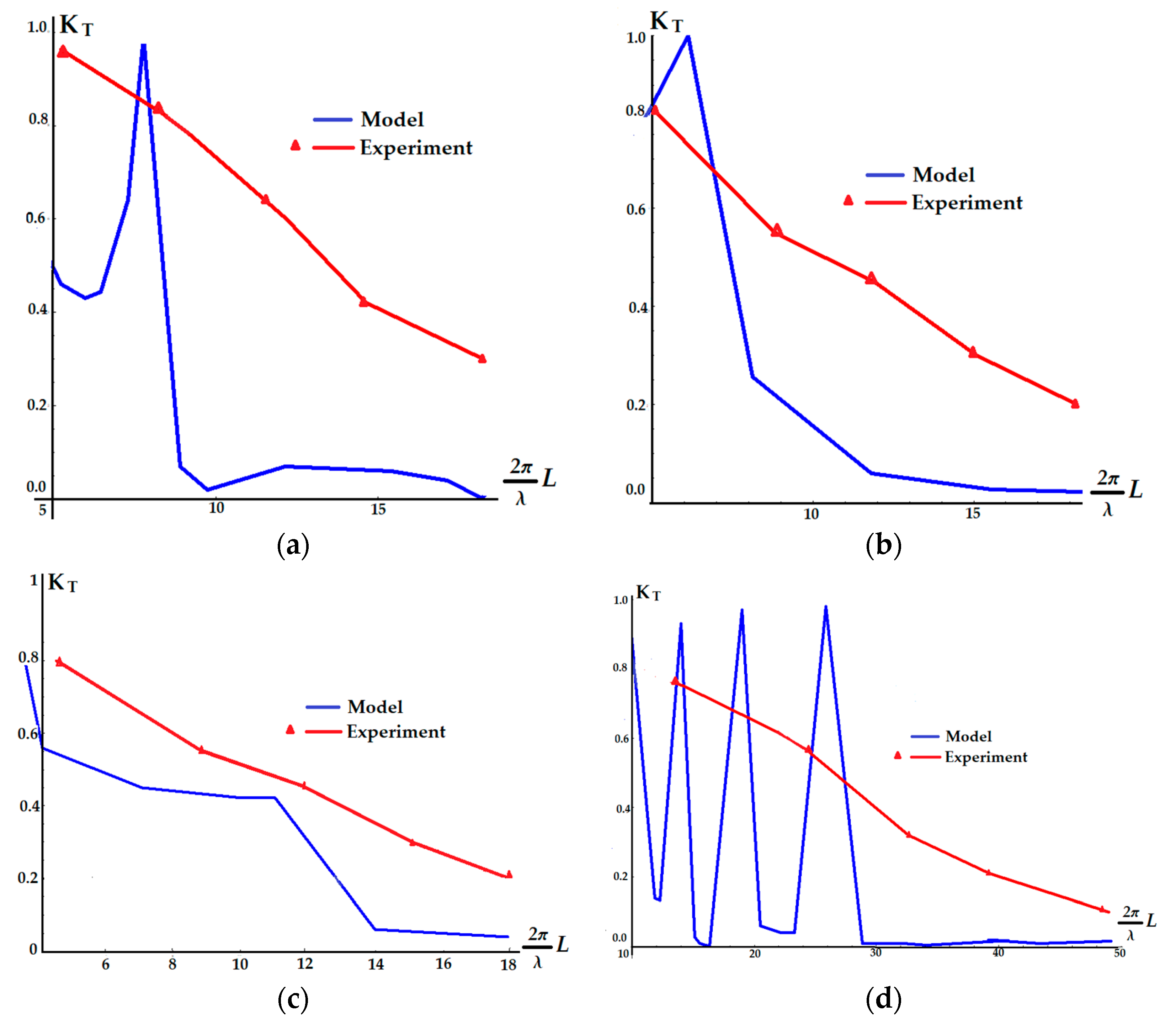
Three elastic materials were tested in the experiments: latex, cool cotton and polyvinyl chloride (PVC) with a very different stiffness and two lengths of plates: 1.9 m and 5.1 m. The results of experiments and numerical calculations of transmission coefficient in dependence of the relative length of incoming waves for all cases are presented in Figure 15a–d. Red lines and triangles (experimental points) correspond to experiments, blue lines—to results of numerical simulations of the model.
One can see in Figure 15a,b,d some spikes where transmittance suddenly jumps to unit-absolute transmittance. This fact has the following physical explanation: elastic plate with fixed edges (zero boundary conditions) has its own system of eigenvalue modes for discrete set of frequencies. If one of these frequencies coincides with the frequency of incoming wave we will have the situation of total transparency and coefficient of transmittance jumps to unit. This fact was fully confirmed by our numerical simulations. This is a local effect just in one point of frequency spectrum and seems to be more formal than practically observable.
As can be seen from the experiments, a very common property of wave propagation is that its amplitude decreases with increasing plate length. Wave attenuation is ineffective for short elastic plates whose length is much less than the length of the incoming wave. Coefficient of wave transmission sharply decreases only when the length of the plate is comparable or more than .
The wave transfer coefficient decreases sharply only when the plate length is comparable or greater than .
6. Conclusions
From the results of the experiments, it is clear that the elastic membrane covering the surface of the water can have a significant effect of suppressing and reducing waves.
The transmission coefficient is mainly related to the steepness of waves, and the reflection is related to the fixing method and the elastic material of the plate.
The steepness of incoming waves has an essential effect on the transmission, reflection and energy loss.
Different water depths have a relatively small effect on the transmission coefficient. (Intermediate water depth)—the greater the relative water depth generates a slightly more energy loss.
Long plates have a large reflection coefficient and a small transmission coefficient. The longer plate gives a less transmission compared to the short plate. The energy absorption of the whole plate is still higher than that of the short plate.
When both ends are fixed, the transmission coefficient is smaller than other methods, and the reflection coefficient is larger.
The reflection coefficient of rigid components is significantly greater than the other two components, while the transmission coefficients are similar. And the characteristics of the reflection coefficient corresponding to the wave steepness of each plate are also different.
The main difference between elastic and rigid components is reflecting in front of the structure. Since the incident wave energy of the rigid plate is converted into reflection, it may cause the structure to be washed in advance.
Various mounting methods: when both ends are fixed, the transmission coefficient is less than other methods, and the reflection coefficient is greater, the influence caused by the cable force or angle can be further explored.
Our theoretical analysis revealed the region of minimum transmission of waves defined by the value of parameter depending from the elasticity, length and other properties of elastic plate. The region of applicability of such a hypothesis needs further experimental and theoretical efforts.
The simulation showed the existence of a discrete set of frequencies of incoming waves with a full transmittance depending on the characteristics of the elastic plate.
Our theoretical estimates are somewhat inconsistent with the experimental results, perhaps for several reasons:
- (1)
- The model is idealized, does not take into account viscosity, nonlinearity, wave overlap, etc.
- (2)
- On the other hand, the experimental conditions are also not fully realized, for example, the conditions of the fixed edges of the plate, overlapping was observed, and drift and rocking, etc.
Nevertheless, on the basis of the conducted studies, it can be argued that a properly designed wave barrier in the form of a horizontal elastic membrane on the water surface can become an effective shore protection structure.
Author Contributions
Conceptualization, I.S., R.-Y.Y., Y.-Y.C.; methodology I.S., R.-Y.Y., Y.-Y.C.; software, I.S., R.-Y.Y.; validation, I.S., R.-Y.Y.; formal analysis, I.S.; investigation, I.S.; resources, R.-Y.Y.; writing—original draft preparation, I.S.; writing—review and editing I.S., R.-Y.Y., Y.-Y.C.; visualization, R.-Y.Y.; supervision, Y.-Y.C.; project administration, Y.-Y.C.; funding acquisition, R.-Y.Y.; All authors have read and agreed the publication of the manuscript.
Funding
The reported study was funding by RFBR and TUBITAK according to the research project 20-55-46005. The study was also funded by the Ministry of Science and Higher Education of the Russian Federation, theme no. 0149-2019-0005.
Acknowledgments
The authors acknowledge the financial support from Ministry of Science and Technology of Taiwan, under Grant Number MOST 106-2221-E-110-036-MY3 for this study.
Conflicts of Interest
The authors declare no conflict of interest. The funders had no role in the design of the study; in the collection, analyses, or interpretation of data; in the writing of the manuscript, or in the decision to publish the results.
References
- John, F. On the Motion of Floating Bodies I. Commun. Pure Appl. Math. 1949, 2, 13–57. [Google Scholar] [CrossRef]
- Black, J.L.; Mei, C.C. Scattering and radiation of surface waves by rectangular obstacles in water of finite depth. J. Fluid Mech. 1969, 38, 499–511. [Google Scholar]
- Black, J.L.; Mei, C.C.; Bray, M.C.G. Radiation and scattering of water waves by rigid bodies. J. Fluid Mech. 1971, 46, 151–164. [Google Scholar] [CrossRef]
- Macagno, E.O. Houle dans un canal presentant un passage en charge. La Houille Blanche 1954, 1, 31–41. [Google Scholar] [CrossRef] [Green Version]
- Ruol, P.; Martinelli, L.; Pezzutto, P. Formula to Predict Transmission for -Type Floating Breakwaters. J. Waterw. Port Coast. Ocean Eng. 2013, 139, 1–8. [Google Scholar] [CrossRef] [Green Version]
- Siew, P.; Hurley, D. Long surface waves incident on a submerged horizontal plate. J. Fluid Mech. 1977, 83, 141–151. [Google Scholar] [CrossRef]
- McIver, M. Diffraction of water waves by a moored horizontal, flat plate. J. Eng. Math. 1985, 19, 297–319. [Google Scholar] [CrossRef]
- Sendil, U.; Graf, W. Transmission of regular waves past floating plates. In Proceedings of the International Conference on Coastal Engineering, Copenhagen, Denmark, 24–28 June 1974; p. 14. [Google Scholar]
- Arunachalam, V.M.; Raman, H. Experimental studies on a perforated horizontal floating plate breakwater. Ocean Eng. 1982, 9, 35–45. [Google Scholar] [CrossRef]
- Cho, I.; Kim, M. Interactions of a horizontal flexible membrane with oblique incident waves. J. Fluid Mech. 1998, 367, 139–161. [Google Scholar] [CrossRef]
- Stiassnie, M.; Drimer, N. On a Freely Floating Porous Box in Shallow Water Waves. Appl. Ocean Res. 2003, 25, 263–268. [Google Scholar] [CrossRef]
- Liang, N.; Huang, J.; Li, C. A study of spar buoy floating breakwater. Ocean Eng. 2004, 31, 43–60. [Google Scholar] [CrossRef]
- Dong, G.H.; Zheng, Y.N.; Li, Y.C.; Teng, B.; Guan, C.T.; Lin, D.F. Experiments on wave transmission coefficients of floating breakwaters. Ocean Eng. 2008, 35, 931–938. [Google Scholar] [CrossRef]
- Wang, H.Y.; Sun, Z.C. Experimental study of a porous floating breakwater. Ocean Eng. 2010, 37, 520–527. [Google Scholar] [CrossRef]
- Shugan, I.V.; Hwung, H.-H.; Yang, R.-Y.; Hsu, W.-Y. Elastic plate as floating wave breaker in a beach zone. Phys. Wavew Phenom. 2012, 20, 199–203. [Google Scholar] [CrossRef]
- Goda, Y.; Suzuki, T. Estimation of incident and reflected waves in random wave experiments. In Proceedings of the 15th Coastal Engineering Conference, Honolulu, HI, USA, 11–17 July 1976; pp. 828–845. [Google Scholar]
- Mansard, E.P.D.; Funke, E.R. The measurement of incident and reflected spectra using a list squares method. In Proceedings of the 17th International Conference on Coastal Engineering, ASCE, New York, NY, USA, 23–28 March 1980; pp. 154–172. [Google Scholar]
- Zelt, J.; Skjelbreia, J. Estimating incident and reflected wave fields using an arbitrary number of wave gauges. In Proceedings of the 23rd ICCE, Venice, Italy, 4–9 October 1992; pp. 777–789. [Google Scholar]
- Marchenko, A.; Semenov, A. Edge waves of shallow liquid under an elastic plate with a crack. Izv. Ross. Akad. Nauk. 1994, 4, 185–189. [Google Scholar]
- Marchenko, A. Resonance interactions of waves in an ice channel. J. Appl. Math Mech. 1997, 61, 931–940. [Google Scholar] [CrossRef]
Figure 1.
Laboratory tank.

Figure 2.
Schematic view of the experimental setup.

Figure 3.
Latex component (Latex): length 1.9 m and 5.1 m; density 147.37 (kg/m3); weight 7 kg, thickness 0.02 m.
Figure 3.
Latex component (Latex): length 1.9 m and 5.1 m; density 147.37 (kg/m3); weight 7 kg, thickness 0.02 m.

Figure 4.
Foam component (Steep cotton): length 1.9 m; density 63.18 (kg/m3); weight 3 kg, thickness 0.02 m.
Figure 4.
Foam component (Steep cotton): length 1.9 m; density 63.18 (kg/m3); weight 3 kg, thickness 0.02 m.

Figure 5.
Rigid member (PVC): length 1.9 m; density 181.05 (kg/m3); weight 8.6 kg, thickness 0.02 m.
Figure 5.
Rigid member (PVC): length 1.9 m; density 181.05 (kg/m3); weight 8.6 kg, thickness 0.02 m.

Figure 6.
The relationship between the steepness of the wave and the transmittance of the latex plate fixed at both edges, water depth a = 0.3 m.
Figure 6.
The relationship between the steepness of the wave and the transmittance of the latex plate fixed at both edges, water depth a = 0.3 m.

Figure 7.
The ratio between the steepness of the incoming wave and the reflection coefficients of the latex plate at a wave height of 2 cm, 4 cm and 6 cm, water depth a = 0.3 m.
Figure 7.
The ratio between the steepness of the incoming wave and the reflection coefficients of the latex plate at a wave height of 2 cm, 4 cm and 6 cm, water depth a = 0.3 m.

Figure 8.
Relationship between wave steepness and energy loss coefficient, water depth a = 0.3 m.

Figure 9.
The relationship between wave steepness and transmission coefficient at different water depths.
Figure 9.
The relationship between wave steepness and transmission coefficient at different water depths.

Figure 10.
The relationship between wave steepness and reflection coefficient at different water depths.
Figure 10.
The relationship between wave steepness and reflection coefficient at different water depths.

Figure 11.
Relationship between wave steepness and transmission coefficient at different plate lengths.
Figure 11.
Relationship between wave steepness and transmission coefficient at different plate lengths.

Figure 12.
Relationship between wave steepness and transmission coefficient at different plate lengths.
Figure 12.
Relationship between wave steepness and transmission coefficient at different plate lengths.

Figure 13.
The relationship between the wave steepness and transmission coefficient of different elastic plates when the wave height is 2, 4 and 6 cm at a fixed water depth 0.3 m.
Figure 13.
The relationship between the wave steepness and transmission coefficient of different elastic plates when the wave height is 2, 4 and 6 cm at a fixed water depth 0.3 m.

Figure 14.
Wave transmission coefficient in dependence of plate elasticity coefficient for different ratios () (a) length of plate L = 1.9 m, (b) length of plate L = 5.1 m. For all cases depth of water a = 0.3 m, thickness of plate = 0.02 m.
Figure 14.
Wave transmission coefficient in dependence of plate elasticity coefficient for different ratios () (a) length of plate L = 1.9 m, (b) length of plate L = 5.1 m. For all cases depth of water a = 0.3 m, thickness of plate = 0.02 m.

Figure 15.
Wave transmission coefficient in dependence of () ratio for different plate materials (a) latex, length of plate L = 1.9 m, . (b) polyvinyl chloride (PVC), length of plate L = 1.9 m, (c) steep cotton, length of plate L = 1.9 m, . (d) latex, length of plate L = 5.1 m. For all cases depth of water a = 0.3 m, thickness of plate = 0.02 m. Red lines and triangles (experimental points) correspond to experiments, blue lines–to results of numerical simulations of the model.

Figure 16.
Wave transmission coefficient in dependence of incoming wave steepness kH/2. Curve (I)—latex, curve (II)—polyvinyl chloride (PVC).
Figure 16.
Wave transmission coefficient in dependence of incoming wave steepness kH/2. Curve (I)—latex, curve (II)—polyvinyl chloride (PVC).


Table 1.
Properties of elastic plates and generated waves.
| Materials | Length L (m) | Density (kg/m3) | Elastic Modulus (GPa) | Depth of Fluid a (m) | Period of Waves (s) | Height of Waves H (cm) |
|---|---|---|---|---|---|---|
| Latex | 1.9 and 5.1 | 147.37 | 0.01 | 0.25 0.3 0.35 | 0.65 0.73 0.81 1 1.45 | 2 4 6 |
| Steep cotton | 1.9 | 63.18 | 0.07 | 0.25 0.3 0.35 | 0.65 0.73 0.81 1 1.45 | 2 4 6 |
| PVC | 1.9 | 181.05 | 3.5 | 0.25 0.3 0.35 | 0.65 0.73 0.81 1 1.45 | 2 4 6 |
Table 2.
Characteristics of generating waves (depth of water a = 0.25 m).
| H (m) | T (s) | (m) | k | ka | ||
|---|---|---|---|---|---|---|
| 0.020 | 0.650 | 0.649 | 0.031 | 9.686 | 2.422 | 0.385 |
| 0.020 | 0.730 | 0.799 | 0.025 | 7.862 | 1.966 | 0.313 |
| 0.020 | 0.810 | 0.951 | 0.021 | 6.608 | 1.652 | 0.263 |
| 0.020 | 1.000 | 1.303 | 0.015 | 4.822 | 1.206 | 0.192 |
| 0.020 | 1.450 | 2.088 | 0.010 | 3.010 | 0.753 | 0.120 |
| 0.040 | 0.650 | 0.649 | 0.062 | 9.686 | 2.422 | 0.385 |
| 0.040 | 0.730 | 0.799 | 0.050 | 7.862 | 1.966 | 0.313 |
| 0.040 | 0.810 | 0.951 | 0.042 | 6.608 | 1.652 | 0.263 |
| 0.040 | 1.000 | 1.303 | 0.031 | 4.822 | 1.206 | 0.192 |
| 0.040 | 1.450 | 2.088 | 0.019 | 3.010 | 0.753 | 0.120 |
| 0.060 | 0.650 | 0.649 | 0.092 | 9.686 | 2.422 | 0.385 |
| 0.060 | 0.730 | 0.799 | 0.075 | 7.862 | 1.966 | 0.313 |
| 0.060 | 0.810 | 0.951 | 0.063 | 6.608 | 1.652 | 0.263 |
| 0.060 | 1.000 | 1.303 | 0.046 | 4.822 | 1.206 | 0.192 |
| 0.060 | 1.450 | 2.088 | 0.029 | 3.010 | 0.753 | 0.120 |
Table 3.
Characteristics of generating waves (depth of water a = 0.3 m).
| H (m) | T (s) | (m) | k | ka | ||
|---|---|---|---|---|---|---|
| 0.020 | 0.650 | 0.655 | 0.031 | 9.595 | 2.879 | 0.458 |
| 0.020 | 0.730 | 0.815 | 0.025 | 7.709 | 2.313 | 0.368 |
| 0.020 | 0.810 | 0.980 | 0.020 | 6.408 | 1.922 | 0.306 |
| 0.020 | 1.000 | 1.372 | 0.015 | 4.580 | 1.374 | 0.219 |
| 0.020 | 1.450 | 2.247 | 0.009 | 2.796 | 0.839 | 0.134 |
| 0.040 | 0.650 | 0.655 | 0.061 | 9.595 | 2.879 | 0.458 |
| 0.040 | 0.730 | 0.815 | 0.049 | 7.709 | 2.313 | 0.368 |
| 0.040 | 0.810 | 0.980 | 0.041 | 6.408 | 1.922 | 0.306 |
| 0.040 | 1.000 | 1.372 | 0.029 | 4.580 | 1.374 | 0.219 |
| 0.040 | 1.450 | 2.247 | 0.018 | 2.796 | 0.839 | 0.134 |
| 0.060 | 0.650 | 0.655 | 0.092 | 9.595 | 2.879 | 0.458 |
| 0.060 | 0.730 | 0.815 | 0.074 | 7.709 | 2.313 | 0.368 |
| 0.060 | 0.810 | 0.980 | 0.061 | 6.408 | 1.922 | 0.306 |
| 0.060 | 1.000 | 1.372 | 0.044 | 4.580 | 1.374 | 0.219 |
| 0.060 | 1.450 | 2.247 | 0.027 | 2.796 | 0. 839 | 0.134 |
Table 4.
Characteristics of generating waves (depth of water a = 0.35 m).
| H (m) | T (s) | (m) | k | ka | ||
|---|---|---|---|---|---|---|
| 0.020 | 0.650 | 0.657 | 0.030 | 9.558 | 3.345 | 0.533 |
| 0.020 | 0.730 | 0.823 | 0.024 | 7.632 | 2.671 | 0.425 |
| 0.020 | 0.810 | 0.999 | 0.020 | 6.292 | 2.202 | 0.350 |
| 0.020 | 1.000 | 1.424 | 0.014 | 4.413 | 1.545 | 0.246 |
| 0.020 | 1.450 | 2.384 | 0.008 | 2.635 | 0.922 | 0.147 |
| 0.040 | 0.650 | 0.657 | 0.061 | 9.558 | 3.345 | 0.533 |
| 0.040 | 0.730 | 0.823 | 0.049 | 7.632 | 2.671 | 0.425 |
| 0.040 | 0.810 | 0.999 | 0.040 | 6.292 | 2.202 | 0.350 |
| 0.040 | 1.000 | 1.424 | 0.028 | 4.413 | 1.545 | 0.246 |
| 0.040 | 1.450 | 2.384 | 0.017 | 2.635 | 0.922 | 0.147 |
| 0.060 | 0.650 | 0.657 | 0.091 | 9.558 | 3.345 | 0.533 |
| 0.060 | 0.730 | 0.823 | 0.073 | 7.632 | 2.671 | 0.425 |
| 0.060 | 0.810 | 0.999 | 0.060 | 6.292 | 2.202 | 0.350 |
| 0.060 | 1.000 | 1.424 | 0.042 | 4.413 | 1.545 | 0.246 |
| 0.060 | 1.450 | 2.384 | 0.025 | 2.635 | 0.922 | 0.147 |
© 2020 by the authors. Licensee MDPI, Basel, Switzerland. This article is an open access article distributed under the terms and conditions of the Creative Commons Attribution (CC BY) license (http://creativecommons.org/licenses/by/4.0/).
Share and Cite
MDPI and ACS Style
Shugan, I.; Yang, R.-Y.; Chen, Y.-Y. An Experimental and Theoretical Study of Wave Damping due to the Elastic Coating of the Sea Surface. J. Mar. Sci. Eng. 2020, 8, 571. https://doi.org/10.3390/jmse8080571
AMA Style
Shugan I, Yang R-Y, Chen Y-Y. An Experimental and Theoretical Study of Wave Damping due to the Elastic Coating of the Sea Surface. Journal of Marine Science and Engineering. 2020; 8(8):571. https://doi.org/10.3390/jmse8080571
Chicago/Turabian StyleShugan, Igor, Ray-Yeng Yang, and Yang-Yih Chen. 2020. "An Experimental and Theoretical Study of Wave Damping due to the Elastic Coating of the Sea Surface" Journal of Marine Science and Engineering 8, no. 8: 571. https://doi.org/10.3390/jmse8080571
Note that from the first issue of 2016, this journal uses article numbers instead of page numbers. See further details here.