Multilayer-Structured Wood Electroless Cu–Ni Composite Coatings for Electromagnetic Interference Shielding


1
College of Material Science and Art Design, Inner Mongolia Agricultural University, Hohhot 010018, China
2
Inner Mongolia Key Laboratory for Sand Shrubs Fibrosis and Energy Development and Utilization, Inner Mongolia Agricultural University, Hohhot 010018, China
*
Authors to whom correspondence should be addressed.
Coatings 2020, 10(8), 740; https://doi.org/10.3390/coatings10080740
Submission received: 6 July 2020
/
Revised: 22 July 2020
/
Accepted: 27 July 2020
/
Published: 29 July 2020
(This article belongs to the Section Surface Characterization, Deposition and Modification)
Abstract
:The lightweight multilayer-structured electromagnetic interference shielding composite coatings with controllable electromagnetic gradient on wood surface were prepared via a simple multiple electroless copper–nickel (Cu–Ni) approach. The surface morphology, conductivity, hydrophobicity property and electromagnetic shielding effectiveness of the composite coatings were investigated. The surface roughness and conductivity of the composite coatings were enhanced with the increase in the number of depositions. The surface morphology demonstrated that the roughness was decreased with the process of multiple electroless. The coatings were compact and homogeneous as the deposition run was three. Here, the Sa (Sa illustrated Surface Roughness) value of coatings was 4.497 μm. The ideal conductivity of composite coatings can be obtained as the number of depositions was four. Electromagnetic shielding effectiveness reached average 90.69 dB in the frequency range from 300 kHz to 2.0 GHz. This study provides a new pathway for fabricating lightweight multilayer-structured electromagnetic interference shielding with controllable electromagnetic gradient and hydrophobic composite coatings-based wood.
1. Introduction
Electromagnetic waves in the GHz range are being widely used in the wireless communication systems, computers, electronic equipment and aircraft fields [1,2]. However, the derived electromagnetic wave pollution and electromagnetic interface problem have seriously restricted their further development [1,2]. Depending on the electromagnetic loss theory, a feasible way to solve such problems is to develop high performance absorption materials [3]. The shielding effectiveness of the electromagnetic shielding materials based on wood due to low cost-effective, lightweight and easy to manufacture, indicating that it had broad prospects. Wood is a kind of natural polymer composite and the chemical components of wood mainly included abundant cellulose, hemicelluloses and lignin [4]. The untreated wood is easy to hydrophilic and moist wood is vulnerable to attack by fungi and termites, resulting in the loss of dimensional stability [4]. A common phenomenon is from wood deformation that arises from moisture loss [5]. Many hydroxyl groups lead to the hydrophilicity of wood. Thus, the water absorption and dimensional stability of wood can be considerably altered via chemical and physical modification, which will be beneficial to the applicability and service life of wood. Moreover, the modified wood via electroless Cu–Ni has ability to shield against electromagnetic radiation or signals. According to the above wood defects, the methods of heat treatment, acetylation and silylation [6], waterproofing agent impregnation [7], nanocrystal coating by hydrothermal process [8,9] and coating coverage were often used to reduce the moisture absorption of wood [10]. Many literatures about modified wood have also been conducted [11,12,13,14]. It is well known that electroless is a method to deposition metals such as Ni and Cu onto an insulating substrate through the catalyzed chemical reduction of solution–phase metal ions at the substrate surface [15]. Ni, Cu, and Ni-based alloy coatings have been deposited onto wood surface to prepare electromagnetic shielding materials [16,17,18,19,20]. The uniform and continuous coatings can exhibit high conductivity and electromagnetic shielding effectiveness. The improving electrical conductivity was an impactful method to obtain ideal electromagnetic shielding efficiency, but the excessive conductivity inevitably promoted strong reflection of electromagnetic waves due to the impedance mismatch [21]. What is noticeable is that single high electrical conductivity or high magnetic permeability will result in poor absorption performance because of the impedance mismatch [22]. Hence, the absorption is a combined result of electrical loss and magnetic loss. In general, the combination of dielectric and magnetic materials is an alternative route. Li et al. have fabricated Fe3O4/CNT composites which exhibited a higher absorption bandwidth between 11 and 18 GHz [23]. Here, an absorption peak was up to −40 dB [23]. Wang et al. have prepared the 0.2-mm-thickness flexible 50Ni–Co–Fe–P/PANI/PI fabric with a superhigh electromagnetic shielding efficiency, favorable electrical conductivity and magnetic properties [21] and an absorption peak was up to ~69.4 dB [21]. Liu et al. have prepared the gradient Fe3O4@rGO/MWCNT/WPU composite with ideal gradient and electrical conductivity, and the electromagnetic shielding effectiveness reached 35.9 dB [24]. However, there have been no reports focusing on this field about the lightweight multilayer electromagnetic interference shielding composite coatings with controllable electromagnetic gradient on wood surface. Wood is natural porous polymer materials and is ideal template to fabricate the lightweight electromagnetic interference shielding materials. The method of multiple electroless Cu and Ni is a simple and easy way to improve the coatings electromagnetic performance and eliminate the lateral advantage of wood. It was necessary to eliminate the lateral advantage of wood to reasonably utilize the composite coatings-based wood.
This article reports a simple multiple electroless Cu–Ni method equipped with the artificially modified coatings technique on pretreated wood samples to improve the conductivity, hydrophobic property and electromagnetic shielding effectiveness of the coatings and decrease the surface roughness of composite coatings. Four Cu/wood, Cu/Ni, Cu/ Cu and Ni/Ni layers with different electrical–magnetic properties can induce multiple reflections at each interface, which promote to the absorption attenuation. Furthermore, highly conductive reflection layer and porous metallization wood promoted the penetrating microwaves reflecting back to absorption layer. The relationship of the electromagnetic shielding effectiveness of Cu and Ni times as a function of the number of deposition steps that were carried out on the samples was also analyzed, and the composite coatings via different deposition steps were characterized via Scanning electron microscopy, Laser copolymerization microscope, Contact angle meter, X-ray photoelectron spectroscopy and Electromagnetic shielding effectiveness test.
2. Materials and Methods
2.1. Reagents and Materials
All reagents were purchased from Tianjin Chemical Reagent Co., Ltd. (Tianjin, China), as shown in Table 1 and Table 2. Nickel sulfate hexahydrate, sodium hypophosphite, trisodium citrate dihydrate, thiourea, ammonium, hydrochloric acid, sodium borohydride and sodium hydroxide: AR, Tianjin, China. copper sulfate pentahydrate, Seignette salt, ethylenediaminetetraacetic acid disodium salt, potassium hexacyanoferrate(II) and formaldehyde: AR, Tianjin, China. The substrate materials were wood and the type of sand paper was #600 and 200.
2.2. Experimental Design
In this study, the electroless Cu–Ni experiment was designed in accordance with Table 3.
2.3. Preparation of Cu–Ni Composite Coatings
In this study, the wood was soaked in water for 120 min and was cut into sizes of 11.0 cm in diameter. Wood was activated by copper sulfate pentahydrate and hydrochloric acid solution. Then, wood was activated by sodium borohydride and sodium hydroxide solution and filtered (Table 2). Lastly, the electroless Cu was conducted with electroless solution (copper sulfate pentahydrate, Seignette salt, ethylenediaminetetraacetic acid disodium salt, potassium hexacyanoferrate(II) and Formaldehyde) for 12 min under pH = 11 at 60 °C (Table 1). Samples were rinsed by distilled water. In addition, the previous processes were repeated once. The fabrication procedures of electroless Ni were described in the Experimental section in detail [5]. Finally, the obtained composite materials were dried for 4 h to measure the other properties.
2.4. Surface Characterization
2.4.1. Laser Copolymerization Microscope
A VK-X150 laser copolymerization microscope (LCM, Keyence, Osaka, Japan) was used.
2.4.2. Scanning Electron Microscopy (SEM)
The coating surface morphology and cross section were obtained using S-3400-N SEM system (Hitachi, Tokyo, Japan).
2.4.3. Electrical Property
The resistance and conductivity were tested on the plated wood surface via a FT-201 (Guangzhou four probe technology Co., Ltd., Guangzhou, China) four point probe resistance meter in the direction of longitudinal and lateral coating, recording for four times of circle and center for one time. The average value was calculated.
2.4.4. Wettability
The wettability of coatings was observed via an YH-12 V (Chengdeyoute Testing Instrument Manufacturing Co. Ltd., Chengde, China) contact angle meter.
2.4.5. X-ray Photoelectron Spectroscopy (XPS) Analysis
The XPS (K-Alpha, Thermo Fisher, Waltham, MA, USA) was conducted with Al Kα source as radiation. The excitation source was monochromatized Al Kα radiation (hν = 1486.68 eV) under 12 kV voltage. The base vacuum degree during operation, spot size and take off angle were less than 3 × 10⁻⁸ Pa, 400 μm and 45°, respectively.
2.4.6. Electromagnetic Shielding Effectiveness
The electromagnetic shielding effectiveness of composite coatings-based wood was measured in the L-band (0.3 × 10³–3.0 × 10³ MHz) using a DR-S01 shielding effectiveness test device (Beijing DR Technology Co., Ltd., Beijing, China) in accordance with the ASTM 4935-2010 (National standard). The thickness of specimens for EMI (Electromagnetic interference) shielding measurement was 1.5 mm. Error value between +0.5 and −0.5 dB and voltage standing wave was less than or equal to1.2. Inserting loss (IL) was less than or equal to 0.5 dB.
3. Results
3.1. Surface Morphology
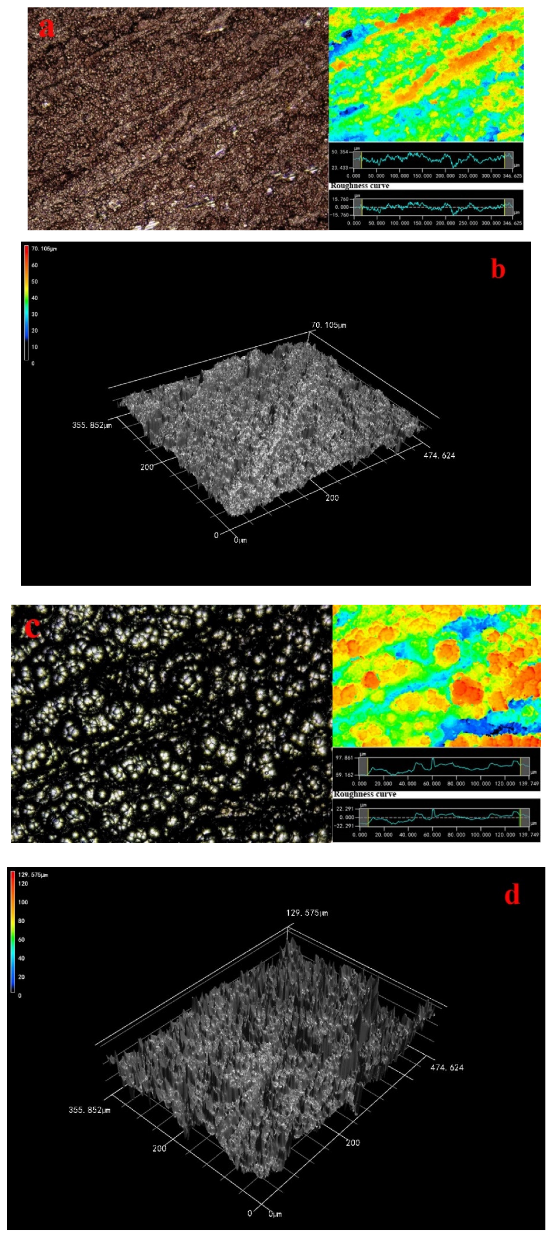
From this fact we can see that many red particles covered the wood surface as shown in Figure 1a. The laser image showed the local red sections appeared, indicating that some ravines had formed on wood surface and the granularity was no larger. Moreover, the roughness curve was smooth. Since this fact can be appreciated we can conclude that 3-D image demonstrated the distribution of many particles on wood surface was a flaky-shaped and the composite coatings on wood surface were even as shown in Figure 1b.
The laser and 3D images showed there were some bright isolated voids on wood surface are as large as 50 μm in Figure 1c,d. The amounts of the ravines had increased, and the homogeneous extent of coatings decreased distinctly as shown in Figure 1c,d. The roughness curve was not smooth, indicating that the Ni particles on Cu coatings surface grew rapidly. Based on previous research, the catalytic activity of substrate surface was critical to the metal ion deposition [5]. The autocatalytic reaction was dependent on the catalytic activity of deposited coatings [25]. The wood surface was conducted two deposition Cu, which undoubtedly promoted the deposition rate of Ni particles.
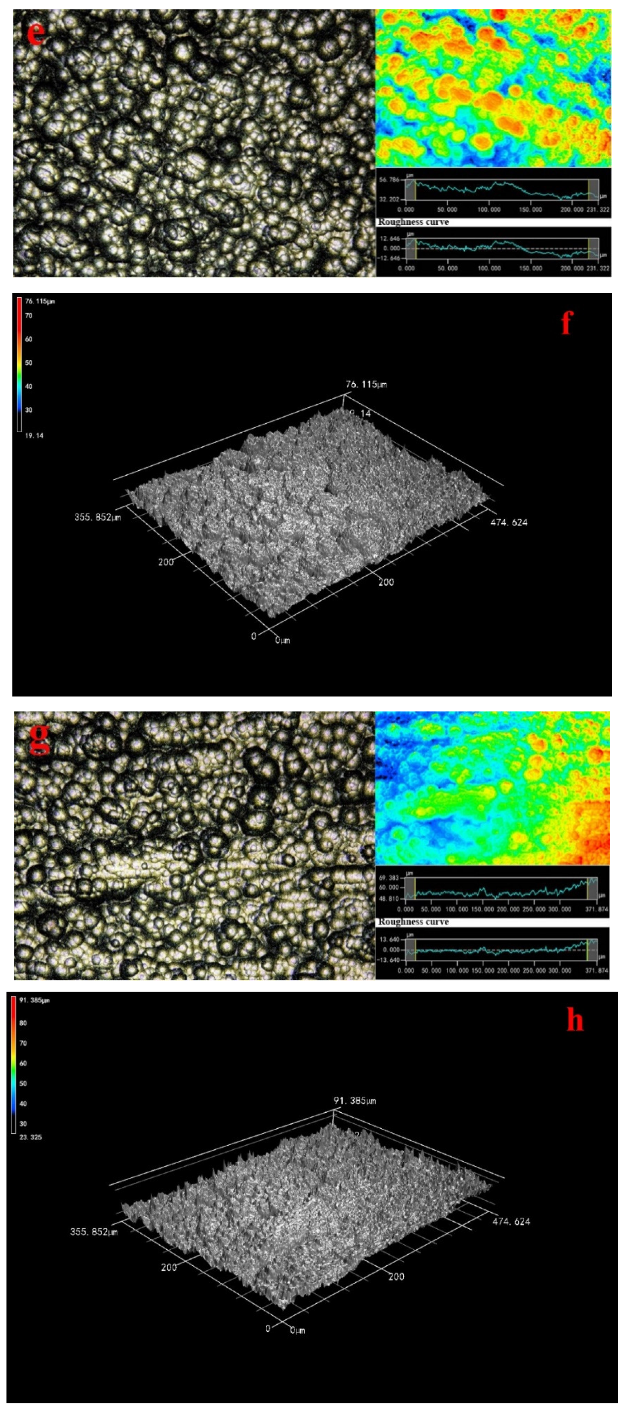
Laser image showed that the morphology of the metal particles was flaky-shaped, which indicated that the growth route of the metal particles made different in Figure 1e in accordance with previous research. The morphology of the metal particles on wood surface was much more homogeneous in 3D image (Figure 1f). The deposition morphology Ni particles was in good condition and the Ni coatings distribution was compact. What is more, the particles were much larger on the wood surface in comparison to Figure 1c. Since this fact can be appreciated we can conclude that the Ni particles on the wood surface were uniform and these agglomerated particles have clearly disappeared in Figure 1a,g,h in comparison to Figure 1c because the Cu coatings were beneficial to form an ideal Ni particles deposition rate [5]. The roughness curve was close to a straight line as shown in Figure 1g. The surface roughness demonstrated that the roughness was decreased with the process of multiple electroless as shown in Table 4 and the surface roughness was improved by 3 times. Here, the ideal Ra (Ra illustrated Line Roughness) and Sa (Sa illustrated Surface Roughness) values of coatings were 4.091 and 4.497 μm, respectively. This study results provided a new pathway for fabricating the homogeneous Cu–Ni composite coatings-based wood. A conclusion can be drawn that the surface roughness was decreased with the process of multiple electroless via characterization of laser image and 3D image.
3.2. Cross-Section Morphology
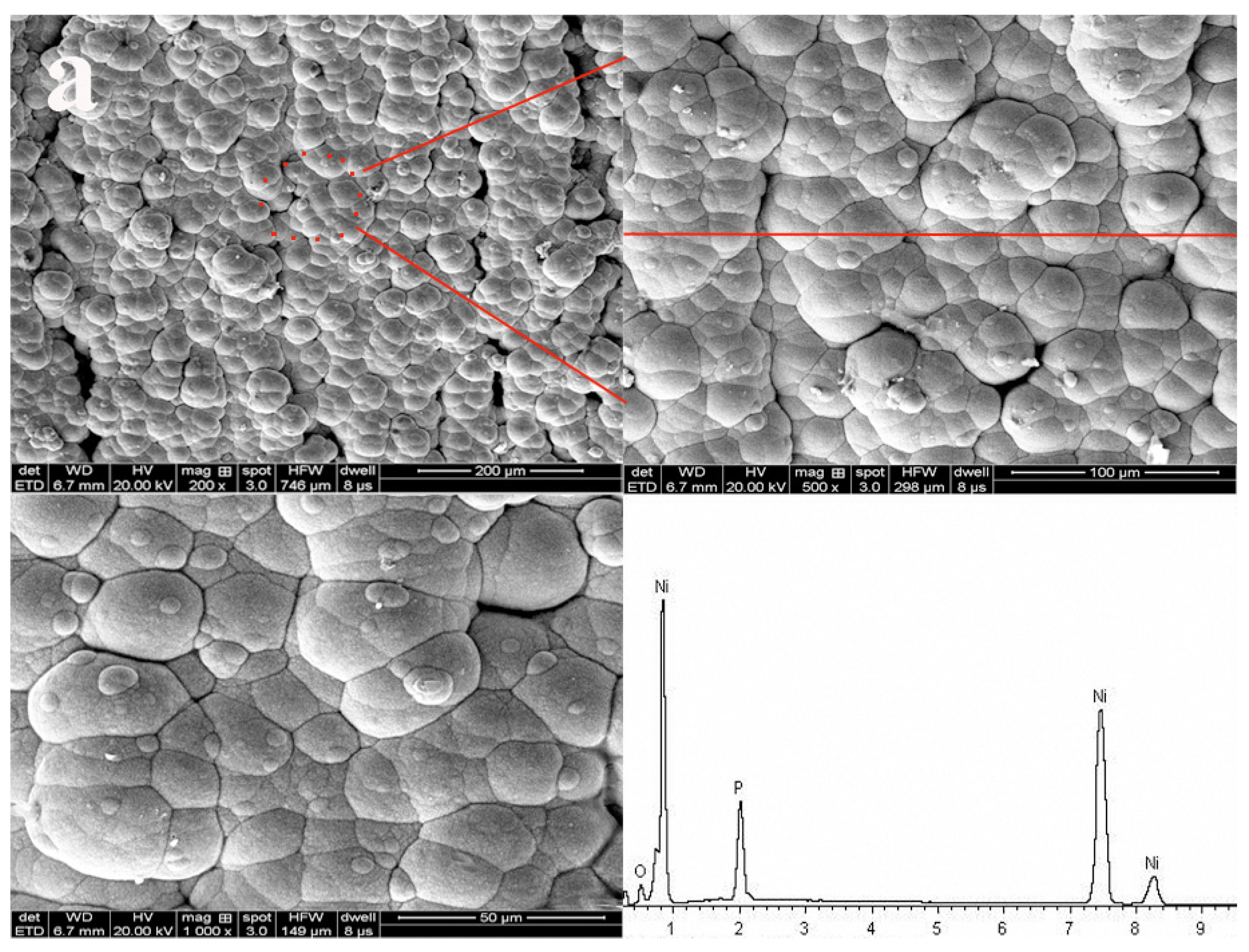
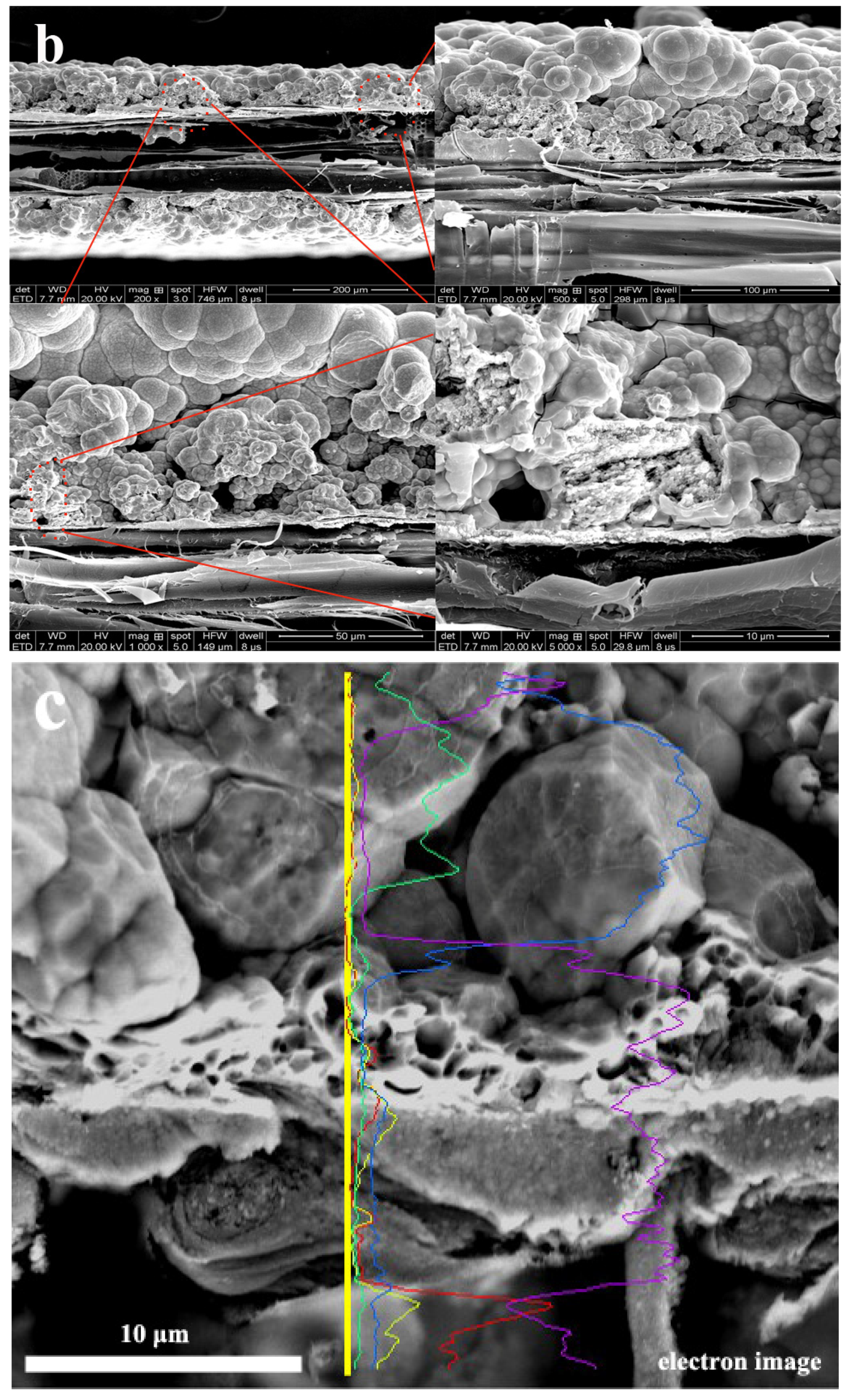
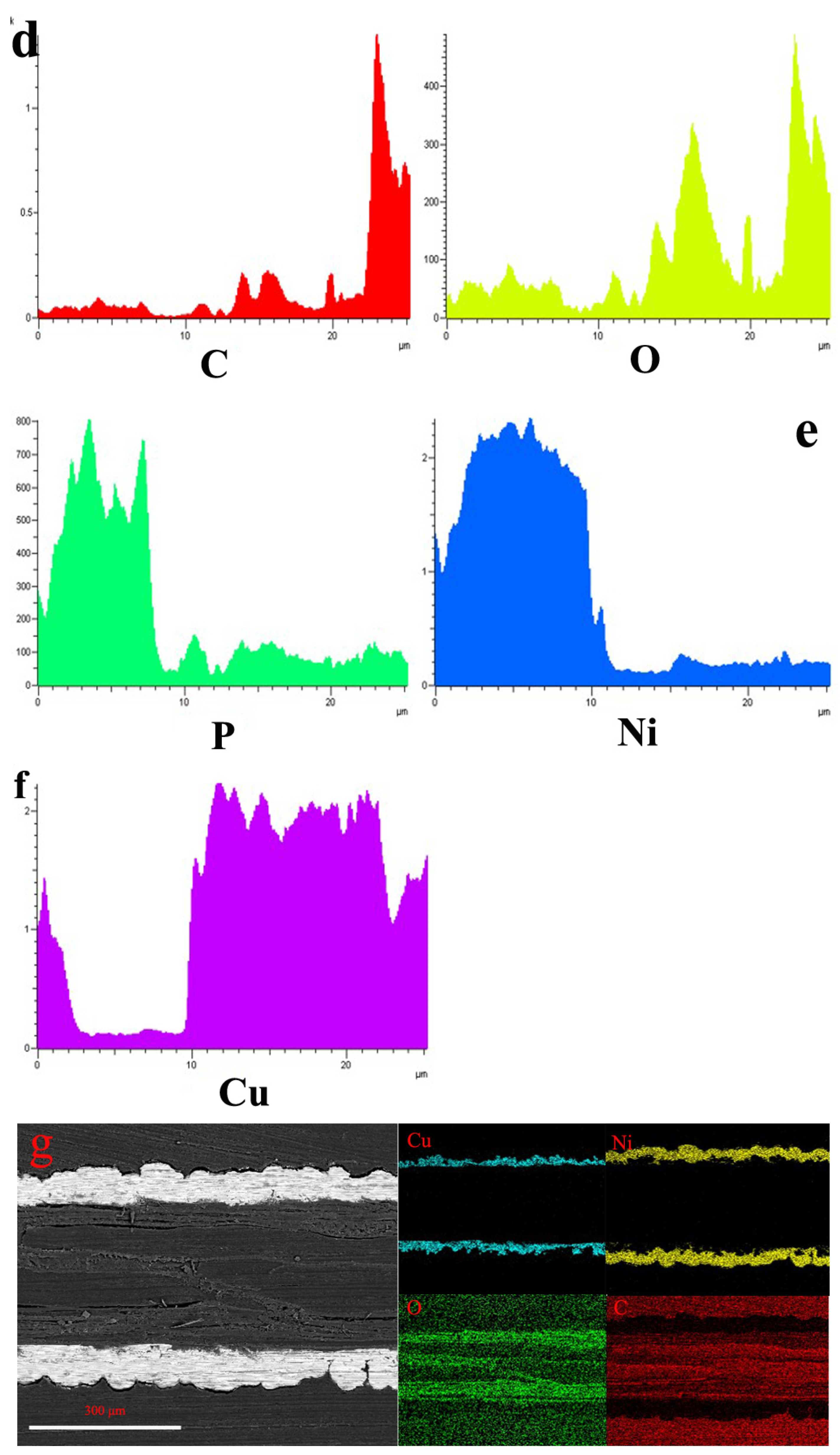
Since this fact can be appreciated we can conclude that metal Cu and Ni particles have penetrated into the interface in Figure 2 and Table 5. The porous wood was covered by metal particles, and the morphology of the metal particles was a flaky-shaped as shown in Figure 2a. It was obvious that the composite coatings are as thick as 200 μm (Figure 2b). The porous texture of wood surface has been filled by Cu and Ni particles, as shown in Figure 2b, indicating that the ideal composite coatings can be obtained. The elements of composites were Ni, Cu, P, C and O elements, respectively, which were mainly located in surface and interface section, which demonstrated the porous structure of the wood was full with fine Cu particles as shown in Figure 2c–g. It was obvious that the wood had a good bond with the metal Cu. According to the cross-section morphology and element composition, it was evidence that the ideal coatings could be fabricated when some specific depositions were conducted as shown in Figure 2.
From this fact we can see that the porous structure of wood was infiltrated with Cu particles and exhibited excellent bonding between substrate and Cu–Ni coatings, indicating that less than four depositions were conducted for that sample as shown in an interface image of Figure 2. The results showed that the ideal interface combination can be obtained with four depositions.
3.3. Electrical Properties
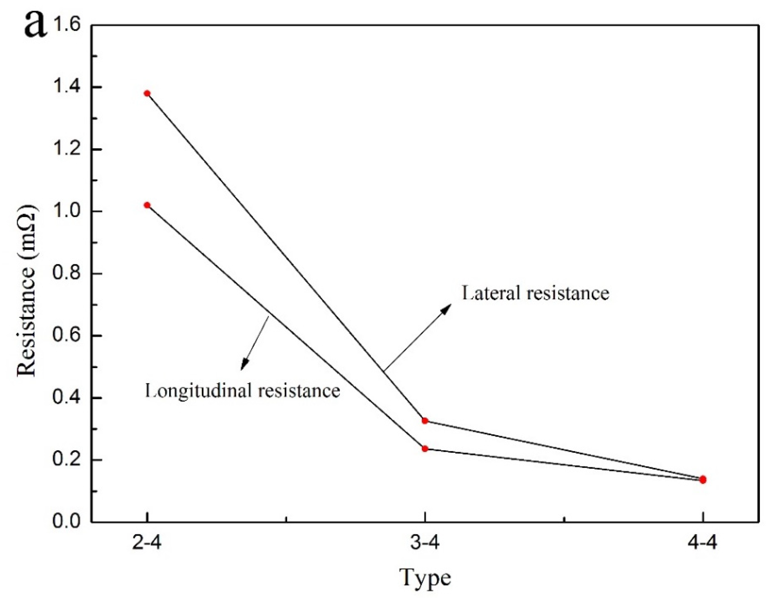
It can be observed that the resistance value was decreased in the number of deposition as shown in Figure 3a. The lateral resistance value was as large as 0.14 mΩ in comparison with longitudinal resistance (Table 6). Figure 3b and Table 7 showed that the conductivity of composite coatings can be up to 8325.2 S/cm as the number of depositions was four.
From this fact we can see that the latter was much larger in comparison with lateral and longitudinal conductivity. Electrical properties can be dramatically enhanced via multiple electroless Cu–Ni, which possessed a significant application value.
It can be observed that the electrical properties of longitudinal composite coatings were ideal because of quite larger cross sectional area in Figure 2. With the process of multiple electroless, the lateral advantage of wood gradually decreased as the coatings became much thicken. In Figure 1b, it can be observed that the distribution of composite coatings was band-shaped in the direction of wood fiber [5]. Some ravines had formed on wood surface, indicating that the cross-sectional area of longitudinal coating on wood surface was larger. Moreover, positive conductivity gradient can be established on wood surface via this method. Therefore, the electrical properties in the direction of longitudinal coatings were ideal in conformity with the experiment results.
3.4. The Hydrophobicity Performance
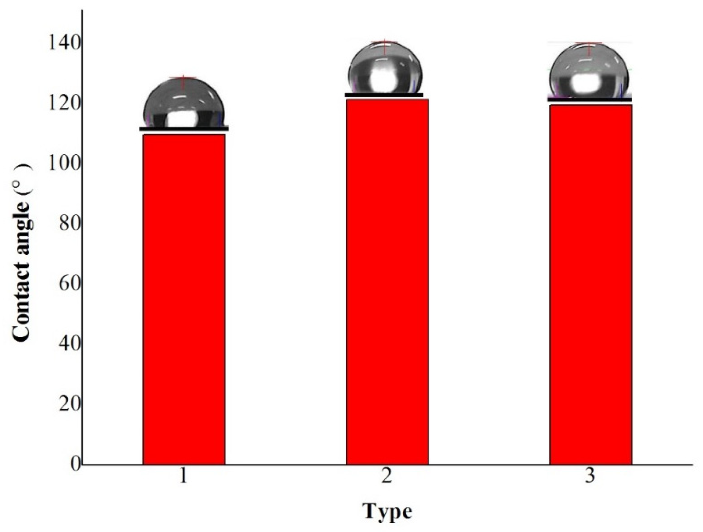
The contact angle of coatings via three depositions was up to 109.59° and it is obvious that the modified wood surface was hydrophobicity as shown Figure 4 and Table 8. The hydrophobicity property was improved with the increase in the deposition number. Figure 4 showed the contact angle of coatings varied in angle between 109.59° and 119.47°. The contact angle increased in the deposition number, which demonstrated that ideal coatings can be obtained. In this case, the hydrophobicity property of wood surface via multiple electroless Cu–Ni can be improved. The uniform degree on wood surface can be enhanced via deposition Cu that was smaller particles and the porous texture of wood surface was filled by Cu particles, which can promote the composite coatings becoming much more homogenous. Moreover, the wood surface was conducted deposition Cu, which promoted the Ni particles deposition rate to promote the hydrophobicity property of wood improved.
3.5. XPS Analysis
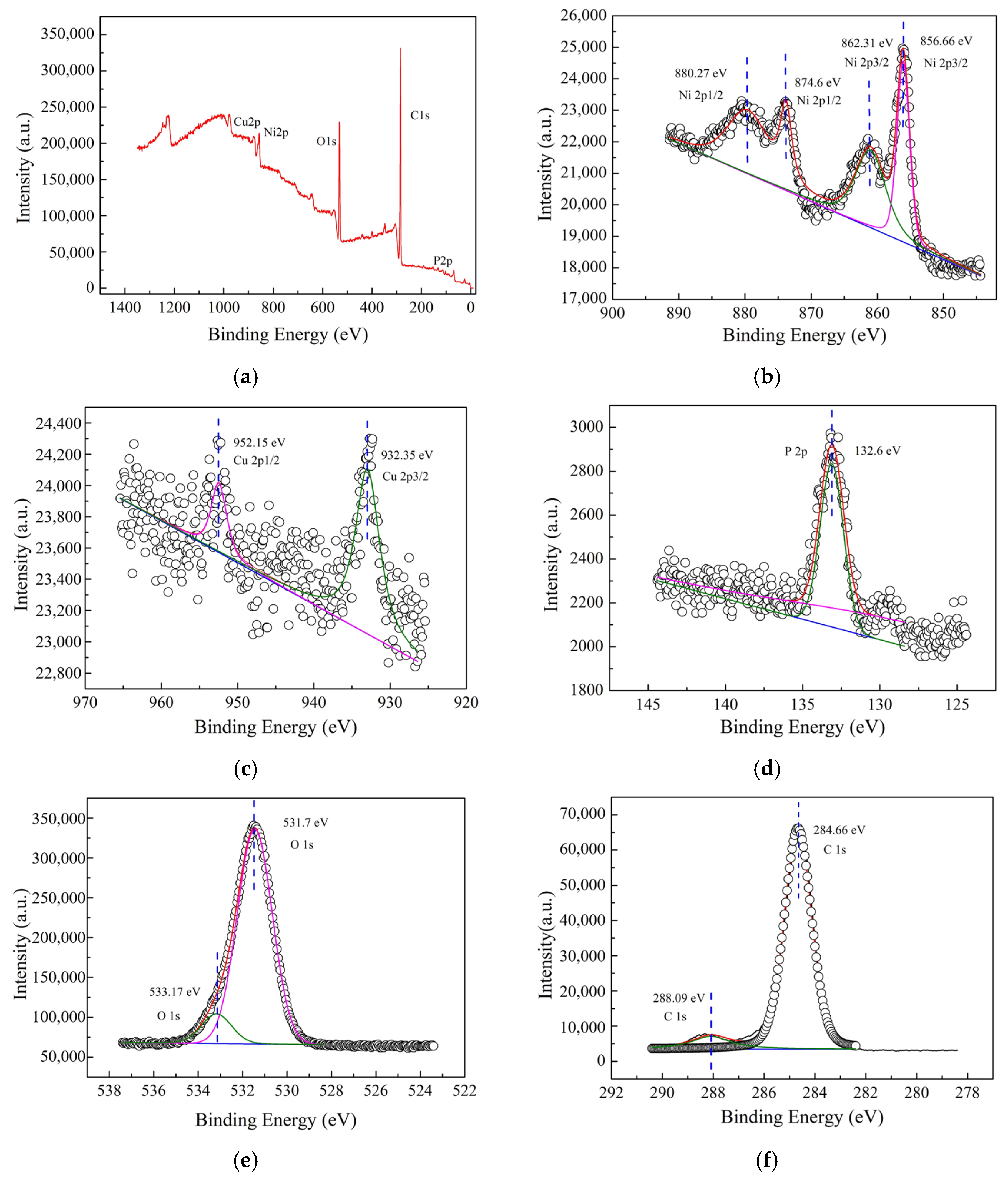
Figure 5 showed the XPS spectrum of composite materials based on wood. XPS analysis of composite materials based on wood was conducted and XPS profiles of Ni 2p, Cu 2p, P 2p, O 1s and C 1s regions were as shown in Figure 5a–f, respectively. Figure 5b presented the Ni 2p spectrum can be deconvoluted into four peaks [26]. The peaks located at 856.66, 862.31, 874.6 and 880.27 eV were characteristic of wood-based composites peak [26]. The peak located at 856.66 eV [27] is assigned to the Ni 2p3/2 state from the Nickelous hydroxide while the peak located at 862.31 eV [27] is assigned to the Ni 2p3/2 state from Ni2+, which demonstrated the coexistence of nickelous hydroxide and Nickel(II) oxide on metallization wood surface. The peaks located at 932.35 eV and 952.15 eV were assigned to the Cu 2p3/2 and Cu 2p1/2 state from the Cu0 as shown in Figure 5c [27]. The peaks located at 132.6 eV [28,29] in Figure 5d correspond to the phosphate (NaH2PO2·H2O) because the composite materials surface can absorb the phosphate. It was obviously seen that the peak at 531.7 eV was from the O 1s spectrum in Figure 5e and it can be assigned to O2− in Nickel(II) oxide [30]. The peaks located at 533.17 eV correspond to the C=O or C–O from wood surface [31]. Figure 5f showed that the peak located at 288.09 eV and 284.66 eV [31] is assigned to the C 1s state from the COOH and C–H, respectively.
The Nickelous hydroxide compound of composite coatings was from the local high value electroless solution. The Ni, O and H elements in the electroless solution can be absorbed and polluted. Moreover, porous structure coatings can absorb some Ni2+ ions and O2. Likewise, the XPS results mentioned above demonstrated the coexistence of Ni and Nickel(II) oxide. The peaks located at 132.6 eV [28,29] in Figure 5d correspond to the phosphate (NaH2PO2·H2O). Some literatures, however, had reported various results. The peaks of Ni 2p on carbon fibers were located at 852.9, 856.0, 870.1 and 874.4 eV [31]. The binding energy of the Ni 2p3/2 peaks was 853.7 eV and 855.2 eV (NiO) [32,33], respectively. There were two chemical states of phosphorus, including elemental phosphorus (P0) and phosphate (P5+) [34]. The elemental phosphorus 2p peaks were present at 130.0 eV (P 2p3/2) and 130.8 eV (P 2p1/2), while the phosphate (PO43−) 2p peak positions were located at 133.6 eV (P 2p3/2) and 134.5 eV (P 2p1/2) [35]. It was obvious that the magnitude of Ni 2p and P 2p shifts caused by the substrate was larger than typical chemical shifts [36,37], indicating that the substrate influence was decisive. Moreover, the results above obtained were different with the literature conclusion mentioned [27,38].
3.6. X-Ray Diffraction (XRD) Analysis
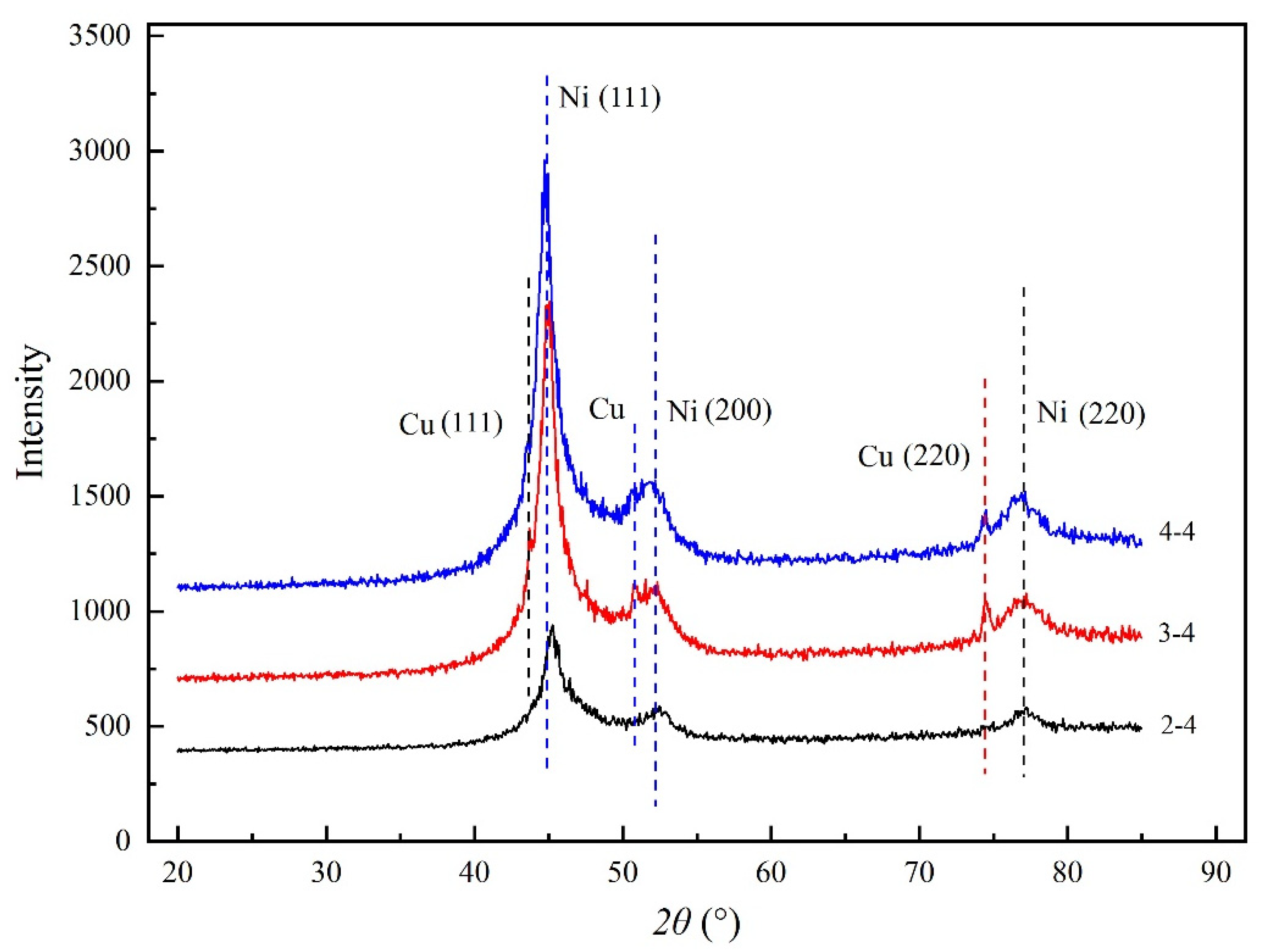
The diffraction peaks at 2θ = 44.5°, 51.84° and 76.37° broadened and strengthened because of Ni (111), Ni (200) and Ni (220) as shown in Figure 6 [5]. The curve labeled 3–4 and 4–4 showed that the diffraction peaks at 2θ = 43°, 50.54° and 74.44° broadened and strengthened because of Cu (111), Cu (200) and Cu (220), which indicated that the Ni and Cu particles had been inset together. A compact wood-based composite coatings can be obtained. The result was accordance with SEM and XPS results. The growth of Ni will improve the growth of Cu crystals, probably because the solid solution was formed between Ni and Cu crystals. It was probably that metal Cu and Ni particles were tightly inset together and a compact composite coatings can be obtained.
The diffraction peaks in the range of 20° to 85° were identified and fitted via the software Jade.5 (version 5.0, Materials Data Inc., Livermore, CA, USA) [5]. The grain size of the Cu–Ni composite coatings can be refined as shown in Table 9. The results demonstrated that the Ni crystallites decreased rapidly and then increased with the increasing in number of deposition steps as shown in Table 9 because the Ni and Cu particles had been inset together.
3.7. Electromagnetic Shielding Effectiveness
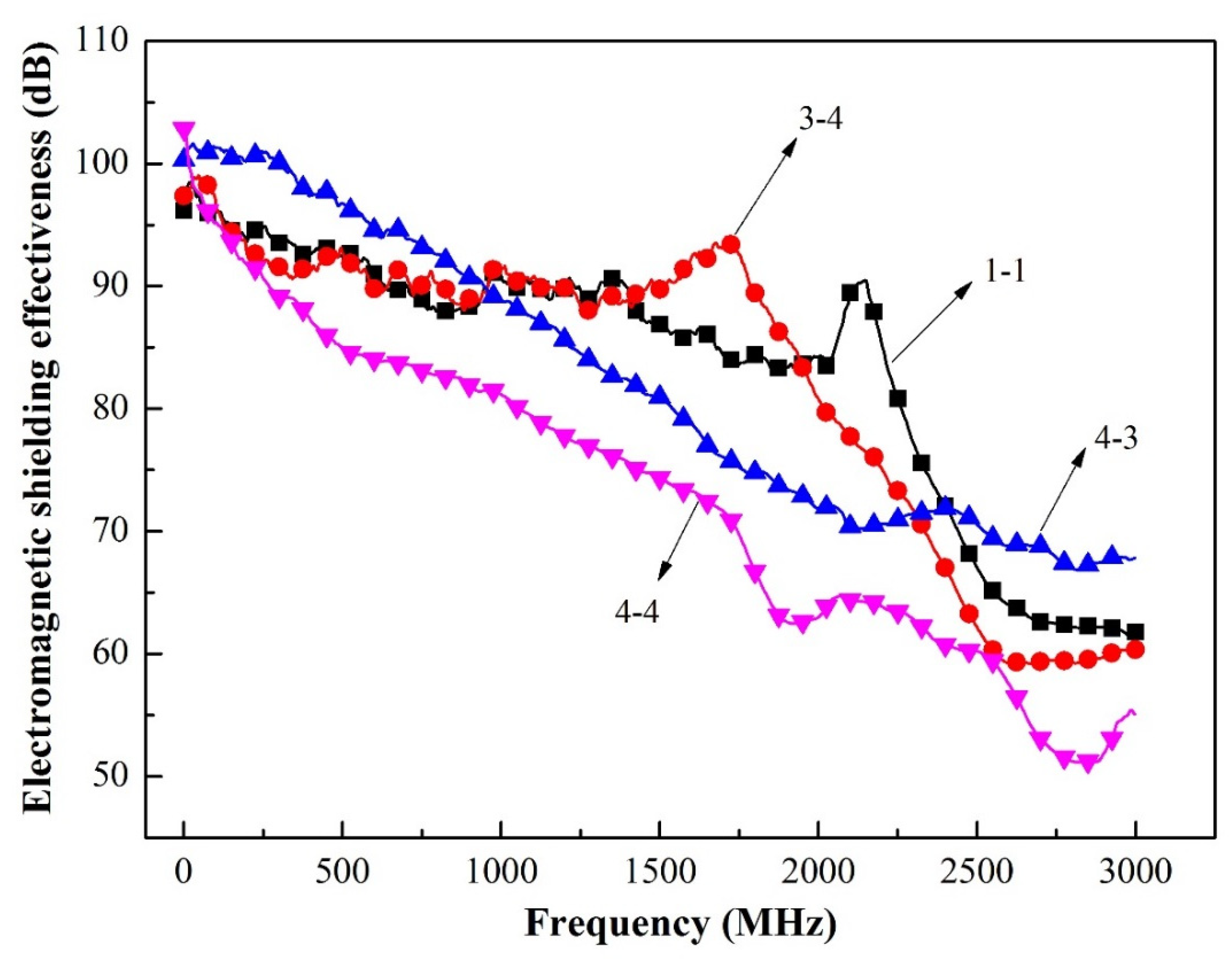
In this section, the electromagnetic shielding effectiveness of composite coatings-based wood was investigated, as shown in Figure 7 and Table 10. The electromagnetic shielding effectiveness of curve labeled 3–4 in the L-band ranging from 300 kHz to 2.0 GHz was relatively stable. The composite coatings via three depositions (curve labeled 3–4) exhibited the optimal shielding performance (average 90.69 dB) in the L-band ranging from 300 kHz to 2.0 GHz while the electromagnetic shielding effectiveness of the composite coatings via four depositions (curve labeled 4–4) was just 80.07 dB. Since this fact can be appreciated we can conclude that the conductive networks and interfacial polarization were considered as the dominant mode during dielectric loss process for microwave absorption materials [24]. Electromagnetic wave shielding in low-frequency was better than high-frequency, and the curve labeled 3–4 exhibited an upward trend ranging from 1.25 GHz to 1.75 GHz, indicating that the high-frequency capability of electromagnetic shielding was greatly enhanced. Thus, the thickness of composite coatings increased in the deposition run, which promoted the ability of electromagnetic wave shielding from high-frequency would be stronger. The composite coatings exhibited the optimal shielding performance (average 90.69 dB) in the L-band ranged from 300 kHz to 2.0 GHz, which demonstrated that the maximum value (electromagnetic shielding effectiveness) was up to 100 dB and the electromagnetic shielding effectiveness was very stable. The electromagnetic shielding effectiveness of the Cu coatings-based wood was only 62 dB ranging from 10 kHz to 1.5 GHz [39,40].
The emerged synergistic effect of Cu and Ni coatings on electromagnetic shielding performance originated from two features of composite coatings-based segregated conductive networks [41,42] and specific interfacial polarization. The ideal conductive networks of composite coatings displayed the superior charge storage capacity, which promoted to absorb more incident electromagnetic microwave energy by the polarization of the electric field [43,44]. At the interface of Cu/wood, Cu/Ni, Cu/Cu and Ni/Ni layers, amounts of free charges can spontaneous accumulated at the heterointerfaces between Cu/wood, Cu/Ni, Cu/Cu and Ni/Ni layers, resulting in macroscopic dipole moments that produced Debye relaxation to attenuate electromagnetic wave [44,45]. Furthermore, conductive loss was undoubtedly another important factor for wave attenuation. The existence of conductive Cu/Ni layer greatly promoted the increase in conductivity. Herein, the conductivity of coatings can be up to 4297.4 S/cm, which could convert electromagnetic energy into heat dissipation [24]. Moreover, the specific morphology of the small sized Cu particles bridged the Ni flakes, leading to the larger polarized interfacial interaction area [46].
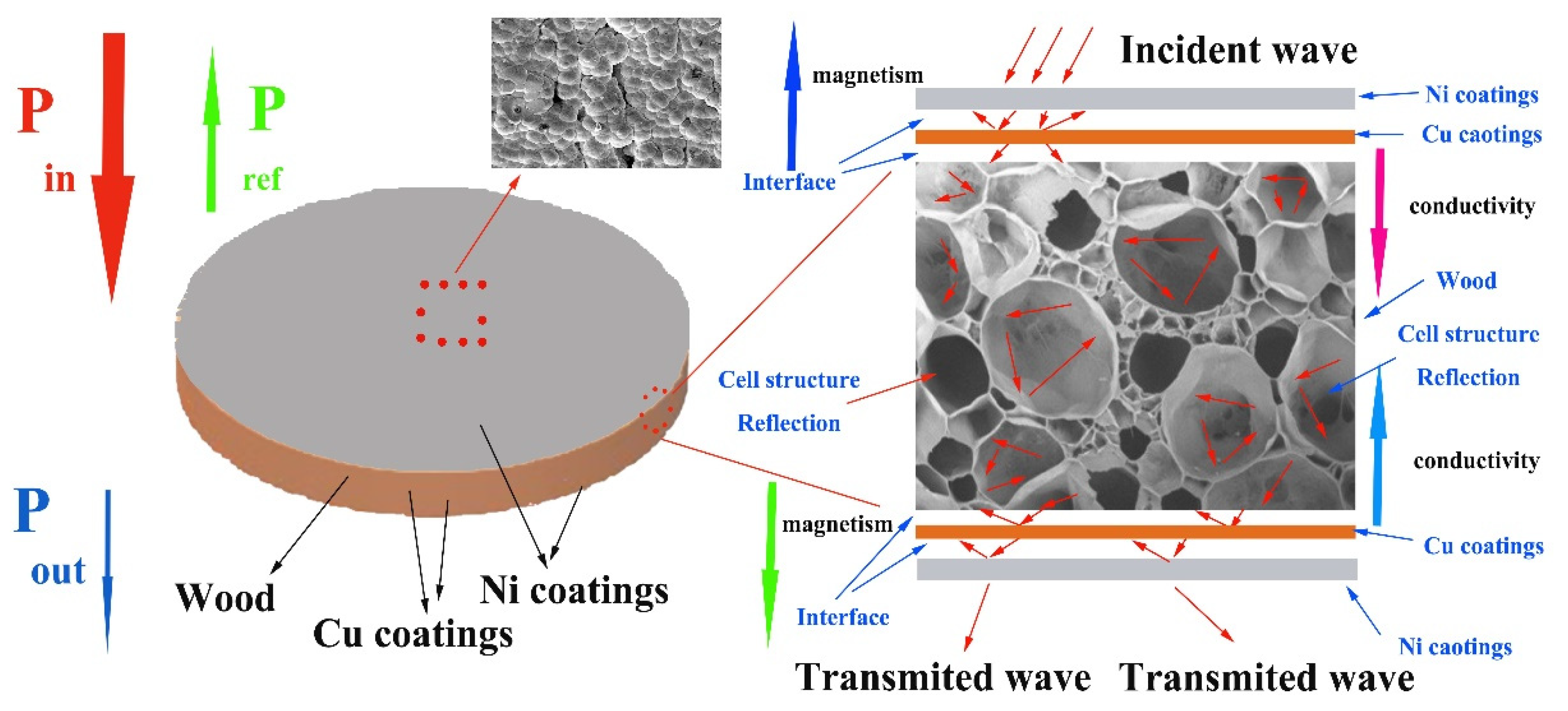
To illustrate this specific shielding route in detail, the electromagnetic shielding mechanism of the multilayer electroless Cu–Ni conductive composite-based wood was demonstrated in Figure 8. The incident electromagnetic waves can easily penetrate into the interior of the composite coatings due to the well impedance matching, and only few of them were reflected on the surface. The absorption layers with positive conductivity gradient and negative magnetism gradient [47] first, provide ideal absorption by strong magnetic hysteresis loss and dielectric loss [47]. Likewise, four Cu/wood, Cu/Ni, Cu/ Cu and Ni/Ni layers with different electrical–magnetic properties can induce multiple reflections at each interface, which promote to the absorption attenuation [24]. Furthermore, highly conductive reflection layer and porous metallization wood promoted the penetrating microwaves reflecting back to absorption layer. The plentiful heterointerfaces between Cu/Ni, Cu/wood and porous metallization wood were produced and thus resulting in polarization relaxation loss to further dissipate electromagnetic waves [24]. Therefore, based on the layered gradient structure design, the multilayer electroless Cu–Ni conductive composite materials-based wood with effective electromagnetic shielding effectiveness exhibited excellent high absorption electromagnetic waves performance.
3.8. Enhanced Mechanism Analysis of Electromagnetic Shielding
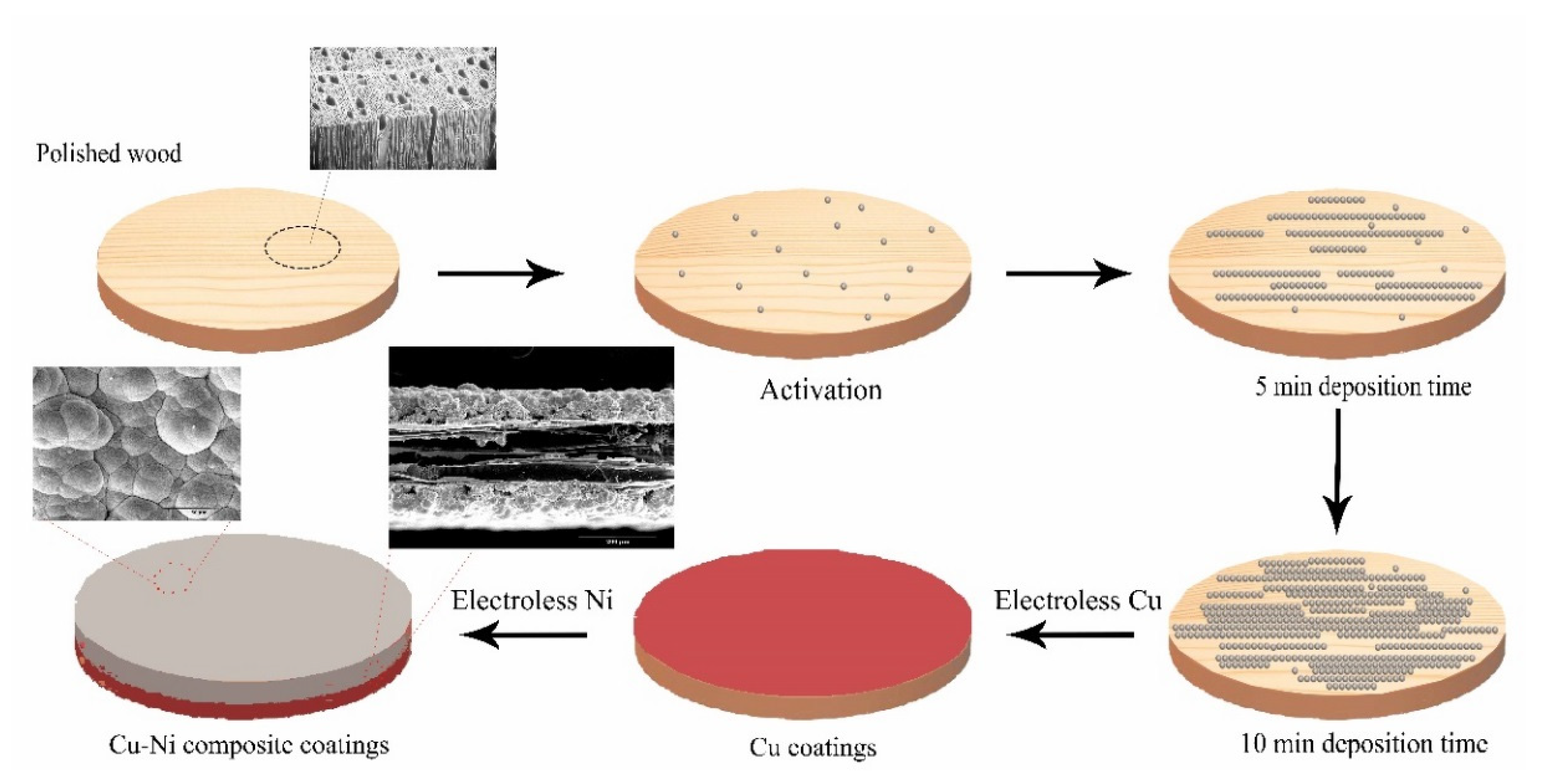
A schematic presentation of the formation of the hydrophobicity and electromagnetic shielding composite coatings-based wood are shown in Figure 9. The growth of wooden cellulose fibers was in the direction of lateral [48]. Some pits which were helpful to deposition coatings can be found on cellulose fibers surface when the wood was activated in solution. The electroless Cu coatings were grown in direction of cellulose fibers. The composite coatings of both sides between wood cellulose fibers were thicker than the middle, which would lead to the cross-sectional area of coatings were larger in the direction of lateral. Figure 1 shows that the morphology of the metal particles was band-shaped. The porous texture of wood surface has been filled by Cu particles due to smaller particles. Moreover, the artificially modified Cu coatings surface via sand paper tended to much better smooth, which was available to deposition Ni. The uniform and compact coatings on wood surface can be obtained with increasing in depositions, indication that the lateral advantage of wood gradually decreased as the coatings became much thicken. Figure 1e,f showed that the morphology of the metal particles was flaky-shaped, which demonstrated that the growth route of the Ni made different. Some ravines formed on wood surface, indicating that the cross-sectional area of longitudinal coating on wood surface was larger. A uniform composite coatings promoted the formation of a good conductive films-based wood, which improved the ability of high-frequency electromagnetic wave shielding [49,50].
In general, the skin depth of the different materials decreased with the increase in conductivity and relative permeability based on Equation (1):
where, δ: skin depth, σ: conductivity (S/cm), f: frequency of electromagnetic wave (Hz), μ0: permeability of vacuum (1.2566 × 10⁻⁶ H/m), μr: relative permeability.
The more obvious the skin effect was, the stronger the material’s ability to absorb and dissipate electromagnetic waves became [50,51]. The skin-depth of Cu and Ni in the frequency of 30 MHz was 12 μm, 2.5 μm, respectively while the frequency was 1.5 GHz, the skin depth was 1.7 μm and 0.36 μm [52,53]. The thickness of composite coatings-based wood was larger than the skin depth, indicating that the induced current was distributed in the surface direction of coatings thickness and electromagnetic wave cannot penetrate. When the thickness was larger than skin depth, the increasing trend of shielding effectiveness tended to be flat with the increase in thickness. Therefore, the electromagnetic shielding effectiveness of the composite coatings cannot increase linearly with the increase in thickness, and the growth trend will inevitably weaken [50].
The good conductive coatings-based wood was obtained via a simple multiple electroless approach, which enhanced the electromagnetic shielding effectiveness [54].
The enhanced the electromagnetic shielding can be explained according to multilayer metal coatings [50]. Figure 10 showed the schematic diagram of double shielding with an interval. According to Equation (2), the electromagnetic shielding effectiveness of double shielding can be illustrated [55]:
where, A representing the total adsorption loss, A = A1 + A2. R representing the total reflect loss.
SSE = A + R + B2
The air was important to the electromagnetic shielding effectiveness of double shielding [50] and the multiple reflecting modified item on inner part of double shielding and double shielding can be simplified in to Equation (3) [50]:
where, β0 is phase constant of electromagnetic wave in air, j is the propagation constant, l is shielding layer spacing (m), N0 is coefficient related to the air wave impedance and impedance of the metal layer.
B2 = 20 × lg|1 − N0e−j·2β0l|
Therefore, the shielding effectiveness of multiple layer materials with interval was generally increased as a whole. Moreover, the shielding effectiveness of multiple composite materials is related to composite materials interval [56]. In general, the shielding effectiveness of double composite materials increased with increase in interval when the electromagnetic wave was low frequency. The electromagnetic wave can penetrate the first layer into the second layer when the interval was less than skin depth. The electromagnetic wave had an obvious attenuation due to multiple reflections occur at intervals between two layers, further indicating that the shielding effectiveness of multiple composite materials was greatly enhanced. A conclusion can be drawn was that the shielding effectiveness of multiple composite materials can be improved via increase in interval in ranging from low frequency.
4. Conclusions
The surface roughness demonstrated that the roughness was decreased with the process of multiple electroless. The coatings were compact and homogeneous as the deposition Cu run was three. Here, the Sa value of composite coatings was 4.497 μm. The longitudinal resistance was as large as 0.134 mΩ and the conductivity of coatings can be up to 8325.2 S/cm as the number of depositions was four. The contact angle of composite coatings-based wood varied in angle between 109.59° and 121.24°. The growth of Ni will improve the growth of Cu crystals, probably because the solid solution was formed between Ni and Cu crystals. The composite coatings-based wood exhibited the optimal electromagnetic shielding performance (average 90.69 dB) in the L-band ranged from 300 kHz to 2.0 GHz. The lightweight multilayer composite coatings with controllable electromagnetic gradient on wood surface can be obtained via a simple multiple electroless Cu–Ni approach.
Author Contributions
Y.P.: conceptualization, methodology, experimentation, validation, data curation, formal analysis, writing—original draft and writing—review and editing. D.Y.: data curation. N.H.: methodology and experimentation. X.Y.: methodology and experimentation. J.H.: conceptualization, methodology, resources, validation, data curation—review and editing and supervision. All authors have read and agreed to the published version of the manuscript.
Funding
This work was supported by Natural Science Foundation of Inner Mongolia Autonomous Region, Grant Number 2019BS03014, The Startup Project of Inner Mongolia Agricultural University High-level Talents Introduction Scientific Research, Grant Number NDYB2016-24, The Colleges and Universities Science Research Project of Inner Mongolia Autonomous Region, Grant Number NJZY18058 and Science and Technology Innovation Leading Project of Inner Mongolia Autonomous Region, Grant Number KCBJ2018013.
Acknowledgments
The authors acknowledge Natural Science Foundation of Inner Mongolia Autonomous Region, The Startup Project of Inner Mongolia Agricultural University High-level Talents Introduction Scientific Research and The Colleges and Universities Science Research Project of Inner Mongolia Autonomous Region (Grant No. 2019BS03014, NDYB2016-24 and NJZY18058).
Conflicts of Interest
The authors declare no conflicts of interest.
References
- Wang, G.Q.; Chen, X.D.; Duan, Y.P.; Liu, S.H. Electromagnetic properties of carbon black and barium titanate composite materials. J. Alloy. Compd. 2008, 454, 340–346. [Google Scholar] [CrossRef]
- Meena, R.S.; Bhattachrya, S.; Chatterjee, R. Development of “tuned microwave absorbers” using U-type hexaferrite. Mater. Des. 2010, 31, 3220–3226. [Google Scholar] [CrossRef]
- Shanenkov, I.; Sivkov, A.; Ivashutenko, A.; Zhuravlev, V.; Guo, Q.; Li, L.P.; Li, G.S.; Wei, G.D.; Han, W. Magnetite hollow microspheres with a broad absorption bandwidth of 11.9 GHz: Toward promising lightweight electromagnetic microwave absorption. Phys. Chem. Chem. Phys. 2017, 19, 19975–19983. [Google Scholar] [CrossRef] [PubMed]
- Fu, Y.C.; Li, G.; Yu, H.P.; Liu, Y.X. Hydrophobic modification of wood via surface-initiated ARGET ATRP of MMA. Appl. Surf. Sci. 2012, 258, 2529–2533. [Google Scholar] [CrossRef]
- Pan, Y.F.; Wang, X.; Huang, J.T. The preparation, characterization, and influence of multiple electroless nickel–phosphorus (Ni-P) composite coatings on poplar veneer. BioResources 2016, 11, 724–735. [Google Scholar] [CrossRef] [Green Version]
- Mohammed-Ziegler, I.; Tánczos, I.; Hórvölgyi, Z.; Agoston, B. Water-repellent acylated and silylated wood samples and their surface analytical characterization. Colloids Surf. A Physicochem. Eng. Asp. 2008, 319, 204–212. [Google Scholar] [CrossRef]
- Mai, C.; Militz, H. Modification of wood with silicon compounds. Treatment systems based on organic silicon compounds-a review. Wood Sci. Technol. 2004, 37, 453–461. [Google Scholar] [CrossRef]
- Li, J.; Yu, H.P.; Sun, Q.F.; Liu, Y.X.; Cui, Y.Z.; Lu, Y. Growth of TiO2 coating on wood surface using controlled hydrothermal method at low temperatures. Appl. Surf. Sci. 2010, 256, 5046–5050. [Google Scholar] [CrossRef]
- Sun, Q.F.; Yu, H.P.; Liu, Y.X.; Li, J.; Lu, Y.; Hunt, J.F. Improvement of water resistance and dimensional stability of wood through titanium dioxide coating. Holzforschung 2010, 64, 757–761. [Google Scholar] [CrossRef]
- Gu, L.B. Current status and application prospects of wood modification. China Wood Ind. 2012, 26, 1–6. [Google Scholar]
- Bakraji, E.H.; Salman, N.; Al-kassiri, H. Gamma-radiation-induced wood-plastic composites from Syrian tree species. Radiat. Phys. Chem. 2001, 61, 137–141. [Google Scholar] [CrossRef]
- Bakraji, E.H.; Salman, N.; Othman, I. Radiation-induced polymerization of acrylamide within Okoume (Aucoumea klaineana Pierre). Radiat. Phys. Chem. 2002, 64, 277–281. [Google Scholar] [CrossRef]
- Bakraji, E.H.; Salman, N. Properties of wood-plastic composites: Effect of inorganic additives. Radiat. Phys. Chem. 2003, 66, 49–53. [Google Scholar] [CrossRef]
- Ebner, M.; Petutschnigg, A.J. Potentials of thermally modified beech (Fagus sylvatica) wood for application in toy construction and design. Mater. Des. 2007, 28, 1753–1759. [Google Scholar] [CrossRef]
- Fujii, S.; Hamasaki, H.; Takeoka, H.; Tsuruoka, T.; Akamatsu, K.; Nakamura, Y. Electroless nickel plating on polymer particles. J. Colloid Interface Sci. 2014, 430, 47–55. [Google Scholar] [CrossRef]
- Li, J.; Wang, L.J.; Liu, H.B. A new process for preparing conducting wood veneers by electroless nickel plating. Surf. Coat. Technol. 2010, 204, 1200–1205. [Google Scholar] [CrossRef]
- Wang, L.J.; Li, J.; Liu, Y.X. Surface characteristics of electroless nickel plated electromagnetic shielding wood veneer. J. For. Res. 2005, 16, 233–236. [Google Scholar]
- Wang, L.J.; Liu, H.B. Electroless nickel plating on chitosan-modified wood veneer. Bioresources 2011, 6, 2035–2044. [Google Scholar] [CrossRef]
- Wang, L.J.; Li, J.; Liu, H.B. A simple process for electroless plating nickel-phosphorus film on wood veneer. Wood Sci. Technol. 2011, 45, 161–167. [Google Scholar] [CrossRef]
- Wang, L.J.; Li, J. Electromagnetic-shielding, wood-based materials created using a novel electroless copper plating process. Bioresources 2013, 8, 3414–3425. [Google Scholar] [CrossRef] [Green Version]
- Mondal, S.; Ghosh, S.; Ganguly, S.; Das, P.; Ravindren, R.; Sit, S.; Chakraborty, G.; Das, N.C. Highly conductive and flexible nano-structured carbon-based polymer nanocomposites with improved electromagnetic-interference-shielding performance. Mater. Res. Express 2017, 4, 105039. [Google Scholar] [CrossRef]
- Wang, Y.; Wang, W.; Ding, X.D.; Yu, D. Multilayer-structured Ni-Co-Fe-P/polyaniline/polyimide composite fabric for robust electromagnetic shielding with low reflection characteristic. Chem. Eng. J. 2020, 380, 108–113. [Google Scholar] [CrossRef]
- Li, N.; Huang, G.W.; Li, Y.Q.; Xiao, H.M.; Feng, Q.P.; Hu, N.; Fu, S.Y. Enhanced microwave absorption performance of coated carbon nanotubes by optimizing the Fe3O4 nanocoating structure. ACS Appl. Mater. Interfaces 2017, 9, 2973–2983. [Google Scholar] [CrossRef] [PubMed]
- Sheng, A.; Ren, W.; Yang, Y.; Yan, D.X.; Duan, H.; Zhao, G.; Liu, Y.; Li, Z.M. Multilayer WPU conductive composites with controllable electro-magnetic gradient for absorption-dominated electromagnetic interference shielding. Compos. Part A 2020, 129, 105692. [Google Scholar] [CrossRef]
- Nagasawa, C.; Kumagai, Y.; Urabe, K.; Shinagawa, S. Electromagnetic shielding particleboard with nickel-plated wood particles. J. Porous Mater. 1999, 6, 247–254. [Google Scholar] [CrossRef]
- He, W.X.; Yu, H.Y.; Zhang, Y.Q.; Li, Z.Q.; Liu, B.; Jiang, M. Preparation and electrochemical properties of Ni(OH)2-carbon nanotube-reduced graphene oxide composites. Acta Mater. Compos. Sinica 2018, 35, 1921–1929. [Google Scholar] [CrossRef]
- Hui, B.; Li, J.; Wang, L.J. Effect of Temperature on Electroless Deposition of Ni-Cu-P Ternary Alloy on Birch Veneer. J. Northeast For. Univ. 2015, 43, 87–95. (In Chinese) [Google Scholar] [CrossRef]
- Moulder, J.F.; Stickle, W.F.; Sobol, P.E. Edited Handbook of X-ray Photoelectron Spectroscopy: Physical Electronics Division; Perkin-Elmer Corporation: Houston, TX, USA, 1992. [Google Scholar]
- Wu, J.; Huang, Q.A.; Zhang, H.; Yan, Z.Q. Electrocatalytic Activity for Hydrogen Evolution Reaction on Electrodeposited Ni-Ce-P Alloy. J. Wuhan Automot. Polytech. Univ. 1999, 21, 29–32. [Google Scholar]
- Li, Q.; Liang, C.L.; Lu, X.F.; Tong, Y.X.; Li, G.R. Ni@NiO core-shell nanoparticle tube arrays with enhanced supercapacitor performance. J. Mater. Chem. A 2015, 3, 6432–6439. [Google Scholar] [CrossRef]
- Hua, Z.S.; Yao, G.C.; Ma, J.; Zhang, Z.G.; Liang, L.S. XPS analysis of nickel layers on carbon fibers. Chin. J. Nonferrous Met. 2011, 21, 165–170. [Google Scholar]
- Lee, J.W.; Ahn, T.; Soundararajan, D.; Koc, J.M.; Kim, J.D. Non-aqueous approach to the preparation of reduced graphene oxide/a-Ni(OH)2 hybrid composites and their high capacitance behavior. Chem. Commun. 2011, 47, 6305–6307. [Google Scholar] [CrossRef] [PubMed]
- Nesbitt, H.W.; Legrand, D.; Bancroft, G.M. Interpretation of Ni2p XPS spectra of Ni conductors and Ni insulators. Phys. Chem. Min. 2000, 27, 357–366. [Google Scholar] [CrossRef]
- Liu, H.; Guo, R.X.; Liu, Y.; Thompson, G.E.; Liu, Z. The effect of processing gas on corrosion performance of electroless Ni–W–P coatings treated by laser. Surface Coat. Technol. 2012, 206, 3350–3359. [Google Scholar] [CrossRef]
- Guo, H.; Liu, X.; Hou, Y.; Xie, Q.; Wang, L.; Geng, H.; Peng, D.L. Magnetically separable and recyclable urchin-like Co-P hollow nanocomposites for catalytic hydrogen generation. J. Power Sources 2014, 260, 100–108. [Google Scholar] [CrossRef]
- Greczynsky, G.; Hultman, L. X-ray photoelectron spectroscopy: Towards reliable binding energy referencing. Prog. Mater. Sci. 2020, 107, 100591. [Google Scholar] [CrossRef]
- Greczynsky, G.; Hultman, L. Compromising science by ignorant instrument calibration-need to revisit half a century of published XPS data. Angew. Chem. 2019, 132, 5034–5038. [Google Scholar] [CrossRef]
- Liu, C.L.; Zhang, G.; Yu, L.; Qu, J.H.; Liu, H.J. Oxygen doping to optimize atomic hydrogen binding energy on NiCoP for highly effcient hydrogen evolution. Small 2018, 14, 1800421. [Google Scholar] [CrossRef]
- Guo, T.C.; Wang, Y.; Huang, J.T. Studies of electroless copper plating on poplar veneer. Bioresources 2016, 11, 6920–6931. [Google Scholar] [CrossRef] [Green Version]
- Wang, L.J.; Li, J.; Liu, Y.X. Study on Preparation of Electromagnetic Shielding Composite by Electroless Copper Plating on Fraxinus Mandshurica Veneer. J. Mater. Eng. 2008, 4, 56–60. [Google Scholar]
- Tao, Y.B.; Li, P.; Shi, S.Q. Effects of carbonization temperature and component ratio on electromagnetic interference shielding effectiveness of woodceramics. Materials 2016, 9, 540. [Google Scholar] [CrossRef]
- Ha, J.H.; Hong, S.K.; Ryu, J.K.; Bae, J.; Park, S.H. Development of multi-functional graphene polymer composites having electromagnetic interference shielding and de-icing properties. Polymers 2019, 11, 2101. [Google Scholar] [CrossRef] [PubMed] [Green Version]
- Yousefi, N.; Sun, X.Y.; Lin, X.Y.; Shen, X.; Jia, J.J.; Zhang, B.; Tang, B.Z.; Chan, M.S.; Kim, J.K. Highly aligned graphene/polymer nanocomposites with excellent dielectric properties for high-performance electromagnetic interference shielding. Adv. Mater. 2014, 26, 5480–5487. [Google Scholar] [CrossRef] [PubMed]
- Liu, Q.H.; Cao, Q.; Bi, H.; Liang, C.Y.; Yuan, K.P.; She, W.; Yang, Y.; Che, R. CoNi@SiO2@TiO2 and CoNi@Air@TiO2 microspheres with strong wideband microwave absorption. Adv. Mater. 2016, 28, 486–490. [Google Scholar] [CrossRef] [PubMed]
- Li, Y.; Liu, X.F.; Nie, X.Y.; Yang, W.W.; Wang, Y.D.; Yu, R.H.; Shui, J. Multifunctional organic-inorganic hybrid aerogel for self-cleaning, heat-insulating, and highly efficient microwave absorbing material. Adv. Func. Mater. 2019, 29, 1807624. [Google Scholar] [CrossRef]
- Cui, C.H.; Yan, D.X.; Pang, H.; Jia, L.C.; Bao, Y.; Jiang, X.; Li, Z.M. Towards Efficient Electromagnetic Interference Shielding Performance for Polyethylene Composites by Structuring Segregated Carbon Black/Graphite Networks. Chin. J. Polym. Sci. 2016, 34, 1490–1499. [Google Scholar] [CrossRef]
- Pan, Y.F. Preparation and Performance of Magnetic Hollow Composite Materials Based Wooden Cellulose Fibers. Ph.D. Thesis, Inner Mongolia Agricultural University, Hohhot, China, 2016. [Google Scholar]
- Liu, Y.X.; Zhao, G.J. Xylology; China Forestry Press: Beijing, China, 2012; pp. 163–164. [Google Scholar]
- Hung, F.S. Material Application of a Transformer Box: A Study on the Electromagnetic Shielding Characteristics of Al–Ta Coating Film with Plasma-Spray Process. Coatings 2019, 9, 495. [Google Scholar] [CrossRef] [Green Version]
- Liang, R.R.; Xiao, H.; Wang, N. Shielding effectiveness of double and multilayer electromagnetic shielding fabric. J. Text. Res. 2017, 38, 51–58. [Google Scholar] [CrossRef]
- Su, Q.C.; Zhao, X.M.; Li, W.B.; Li, J.X. Simulation analysis of woven fabric electromagnetic shielding effectiveness using finite integration technique. J. Text. Res. 2016, 37, 155–160. [Google Scholar] [CrossRef]
- Henn, A.R.; Cribbc, R.M. Modeling the shielding effectiveness of metallized fabrics. In Proceedings of the International Symposium on Proceeding of Electromagnetric Compatibility, Anaheim, CA, USA, 17–21 August 1992; pp. 283–286. [Google Scholar]
- Hu, D.W.; Huang, X.Y.; Li, S.T.; Jiang, P.K. Flexible and durable cellulose/MXene nanocomposite paper for efficient electromagnetic interference shielding. Compos. Sci. Technol. 2020, 188, 107995. [Google Scholar] [CrossRef]
- Vovchenko, L.; Matzui, L.; Oliynyk, V.; Milovanov, Y.; Mamunya, Y.; Volynets, N.; Plyushch, A.; Kuzhir, P. Polyethylene composites with segregated carbon nanotubes network: Low frequency plasmons and high electromagnetic interference shielding efficiency. Materials 2020, 13, 1118. [Google Scholar] [CrossRef] [Green Version]
- Yang, K.J. Electromagnetic Compatibility Principle and Design; Posts and Telecom Press: Beijing, China, 2004; pp. 54–55. [Google Scholar]
- Araki, Y.F. The Shielding Design of Electronic Equipment; National Defence Industry Press: Beijing, China, 1975; pp. 126–136. [Google Scholar]
Figure 1.
Morphology of composite coatings 200× (a) 4-0; (b) 3D image; (c) 2-4; (d) 3D image; (e) 3-4; (f) 3D image; (g) 4-4; (h) 3D image, inset shows a roughness image and surface laser image.
Figure 1.
Morphology of composite coatings 200× (a) 4-0; (b) 3D image; (c) 2-4; (d) 3D image; (e) 3-4; (f) 3D image; (g) 4-4; (h) 3D image, inset shows a roughness image and surface laser image.


Figure 2.
Cross-section morphology (a) surface morphology, inset shows EDS images; (b) interface morphology; (c) interface morphology; (d) C and O elements; (e) P and Ni elements; (f) Cu element; (g) interface morphology and element composition distribution.
Figure 2.
Cross-section morphology (a) surface morphology, inset shows EDS images; (b) interface morphology; (c) interface morphology; (d) C and O elements; (e) P and Ni elements; (f) Cu element; (g) interface morphology and element composition distribution.


Figure 3.
Electrical properties. (a) Resistance; (b) conductivity.


Figure 4.
Contact angle of composite materials with different depositions (1:3–0, 2:3–2, 3:4–2).

Figure 5.
XPS spectra. (a) Survey spectrum; (b) Ni 2p; (c) Cu 2p; (d) P 2p, (e) O 1s, (f) C 1s.

Figure 6.
XRD.

Figure 7.
Electromagnetic shielding curve.

Figure 8.
Process of multilayer coatings electromagnetic wave attenuation.

Figure 9.
Schematic illustration of electroless Cu–Ni process.

Figure 10.
Schematic diagram of double shielding with an interval (E electric field distribution, S electromagnetic wave direction of propagation, H magnetic field distribution, Zr impedance of free space, Zw wave impedance of wood, L0 coatings thickness, L substrate thickness) [46], 1 and 2 composite coatings.


Table 1.
Electroless Cu–Ni solution.
| Solution Component | Content |
|---|---|
| Copper sulfate pentahydrate | 53 g·L−1 |
| Seignette salt | 13 g·L−1 |
| Ethylenediaminetetraacetic acid disodium salt | 27 g·L−1 |
| Potassium hexacyanoferrate(II) | 1.3 g·L−1 |
| Formaldehyde | 70 mL·L−1 |
Table 2.
Activation solution.
| Activation Solution Component | Content |
|---|---|
| Copper sulfate pentahydrate | 15 g·L−1 |
| Hydrochloric acid | 12 mL·L−1 |
| Sodium hydroxide | 15 g·L−1 |
| Sodium borohydride | 12 g·L−1 |
Table 3.
Experimental design.
| Type | One Deposition Ni (1) | Two Depositions Ni (2) | Three Depositions Ni (3) | Four Depositions Ni (4) |
|---|---|---|---|---|
| Two depositions Cu (2) | 2-1 | 2-2 | 2-3 | 2-4 |
| Three depositions Cu (3) | 3-1 | 3-2 | 3-3 | 3-4 |
| Four depositions Cu (4) | 4-1 | 4-2 | 4-3 | 4-4 |
Table 4.
Cu–Ni composite coatings surface roughness.
| Type | 2-4 | 3-4 | 4-4 | 4-0 |
|---|---|---|---|---|
| (μm) | (μm) | (μm) | (μm) | |
| Ra | 6.514 | 4.091 | 3.587 | 5.170 |
| Sa | 16.491 | 4.497 | 5.714 | 6.390 |
Table 5.
Composition of surface coatings characterized by EDS.
| Coatings Type | Elements Composition (wt.%) | |||
|---|---|---|---|---|
| Ni | P | C | O | |
| Cu–Ni | 78.23 | 9.91 | 9.25 | 2.61 |
Table 6.
Relationship between electroless times and composite coatings resistance.
| Type | Lateral Resistance (mΩ) | Longitudinal Resistance (mΩ) |
|---|---|---|
| 2-4 | 1.38 | 1.02 |
| 3-4 | 0.326 | 0.236 |
| 4-4 | 0.14 | 0.134 |
Table 7.
Relationship between electroless times and composite coatings conductivity.
| Type | Lateral Conductivity (S/cm) | Longitudinal Conductivity (S/cm) |
|---|---|---|
| 2-4 | 763.56 | 1050.96 |
| 3-4 | 3736.2 | 4297.4 |
| 4-4 | 7396.2 | 8325.2 |
Table 8.
Relation between the number of deposition and contact angle.
| Type of Deposited Coating | Contact Angle (°) |
|---|---|
| 3-0 | 109.59 |
| 3-2 | 121.24 |
| 4-2 | 119.47 |
Table 9.
Integral breadth values and calculated values of the crystallite size of the (111) nickel peak as a function of the number of depositions.
Table 9.
Integral breadth values and calculated values of the crystallite size of the (111) nickel peak as a function of the number of depositions.
| Number of Depositions | Integral Breadth β (radians) | Calculated Crystallite Size (D) (Å) |
|---|---|---|
| 4-0 | 0.318 | 285 |
| 2-4 | 1.670 | 52 |
| 3-4 | 0.324 | 280 |
| 4-4 | 0.520 | 169 |
Table 10.
Relation between the number of deposition and electromagnetic shielding effectiveness (300 KHz to 2.0 GHz).
Table 10.
Relation between the number of deposition and electromagnetic shielding effectiveness (300 KHz to 2.0 GHz).
| Type of Deposited Coating | Electromagnetic Shielding Effectiveness (dB) |
|---|---|
| 1-1 | 89.59 |
| 3-4 | 90.69 |
| 4-3 | 88.31 |
| 4-4 | 80.07 |
© 2020 by the authors. Licensee MDPI, Basel, Switzerland. This article is an open access article distributed under the terms and conditions of the Creative Commons Attribution (CC BY) license (http://creativecommons.org/licenses/by/4.0/).
Share and Cite
MDPI and ACS Style
Pan, Y.; Yin, D.; Yu, X.; Hao, N.; Huang, J. Multilayer-Structured Wood Electroless Cu–Ni Composite Coatings for Electromagnetic Interference Shielding. Coatings 2020, 10, 740. https://doi.org/10.3390/coatings10080740
AMA Style
Pan Y, Yin D, Yu X, Hao N, Huang J. Multilayer-Structured Wood Electroless Cu–Ni Composite Coatings for Electromagnetic Interference Shielding. Coatings. 2020; 10(8):740. https://doi.org/10.3390/coatings10080740
Chicago/Turabian StylePan, Yanfei, Dingwen Yin, Xiaofang Yu, Nanyi Hao, and Jintian Huang. 2020. "Multilayer-Structured Wood Electroless Cu–Ni Composite Coatings for Electromagnetic Interference Shielding" Coatings 10, no. 8: 740. https://doi.org/10.3390/coatings10080740
Note that from the first issue of 2016, this journal uses article numbers instead of page numbers. See further details here.