Research on Stress Characteristics of Segment Structure during the Construction of the Large-Diameter Shield Tunnel and Cross-Passage


Abstract
:1. Introduction
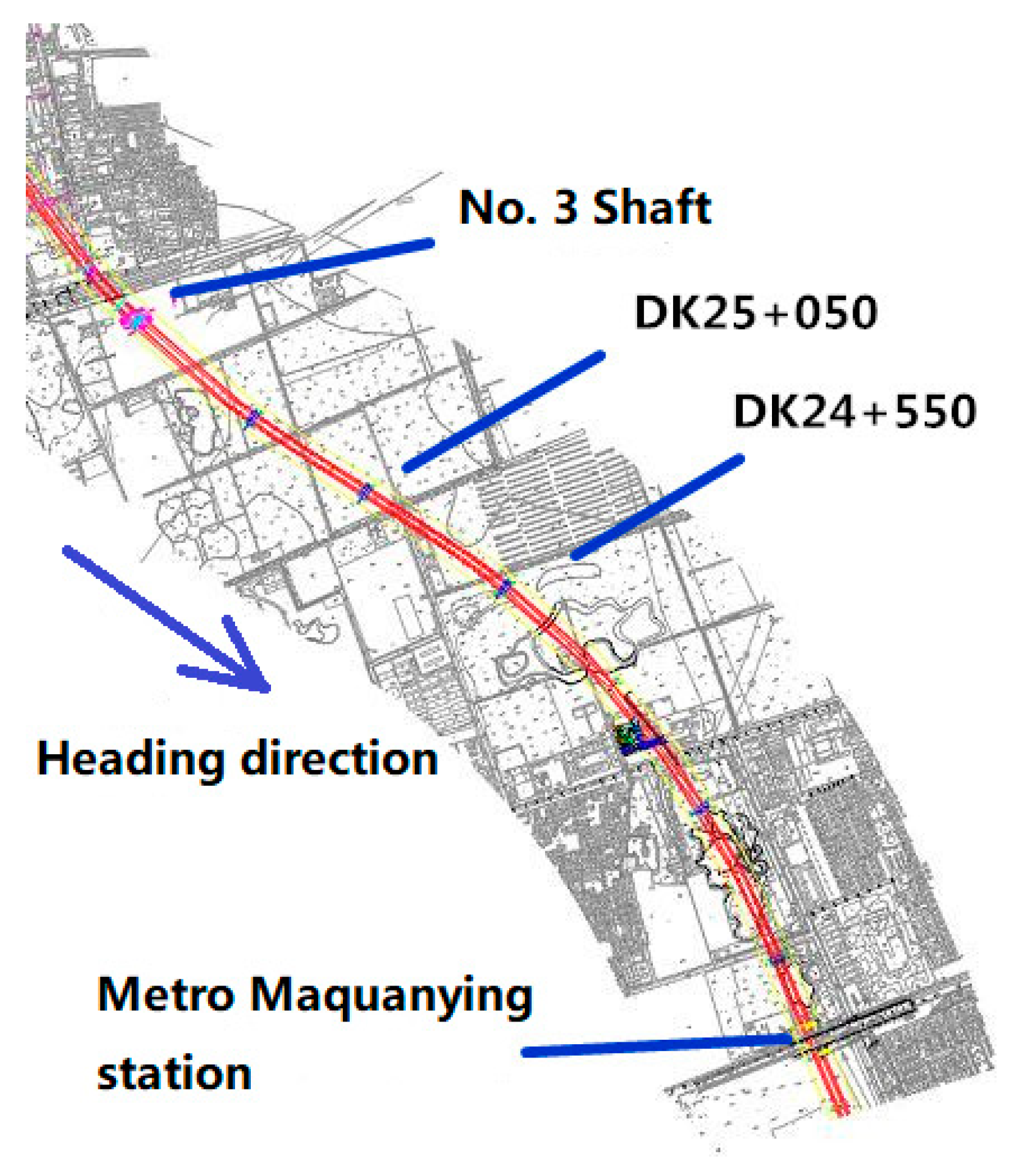
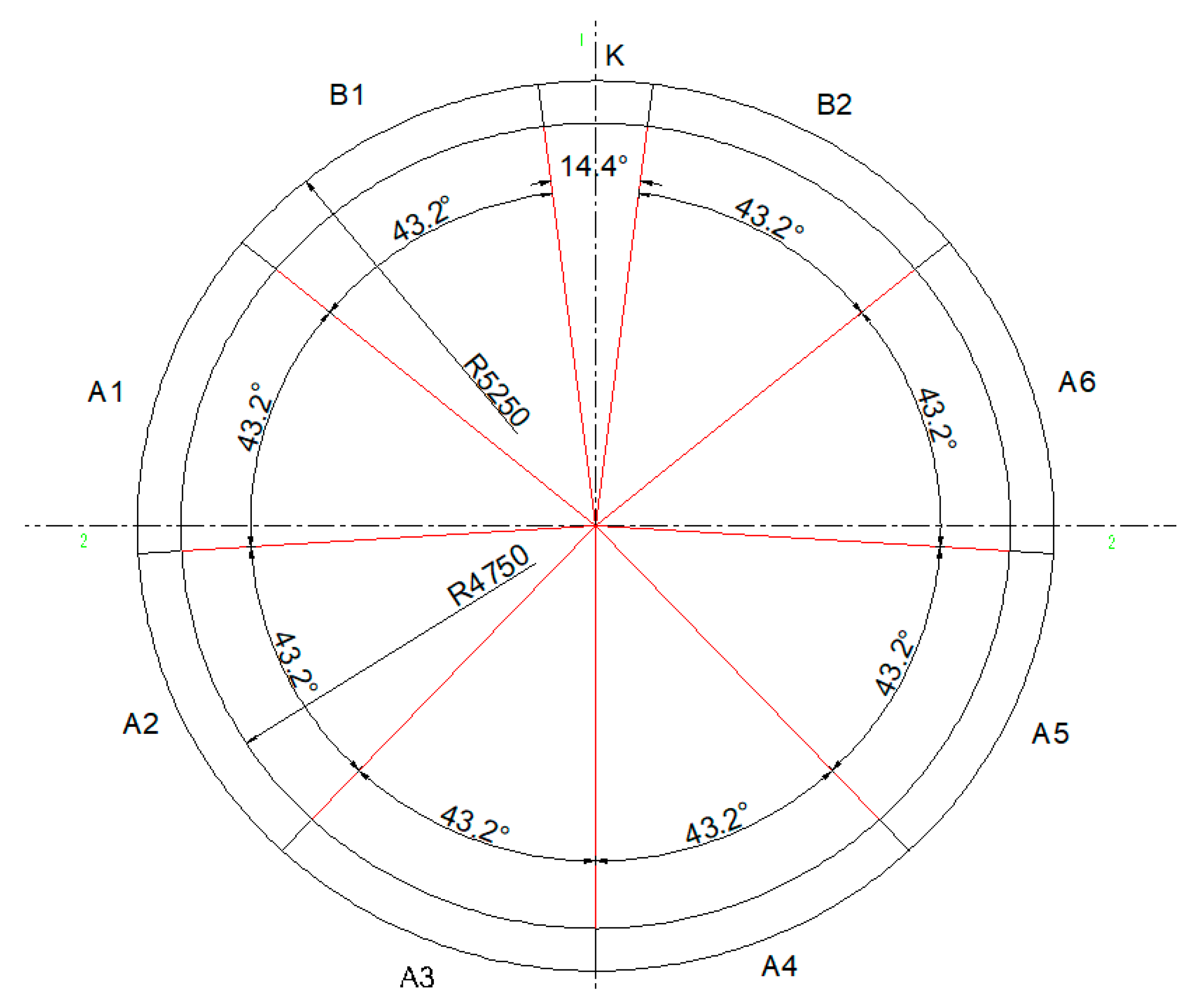
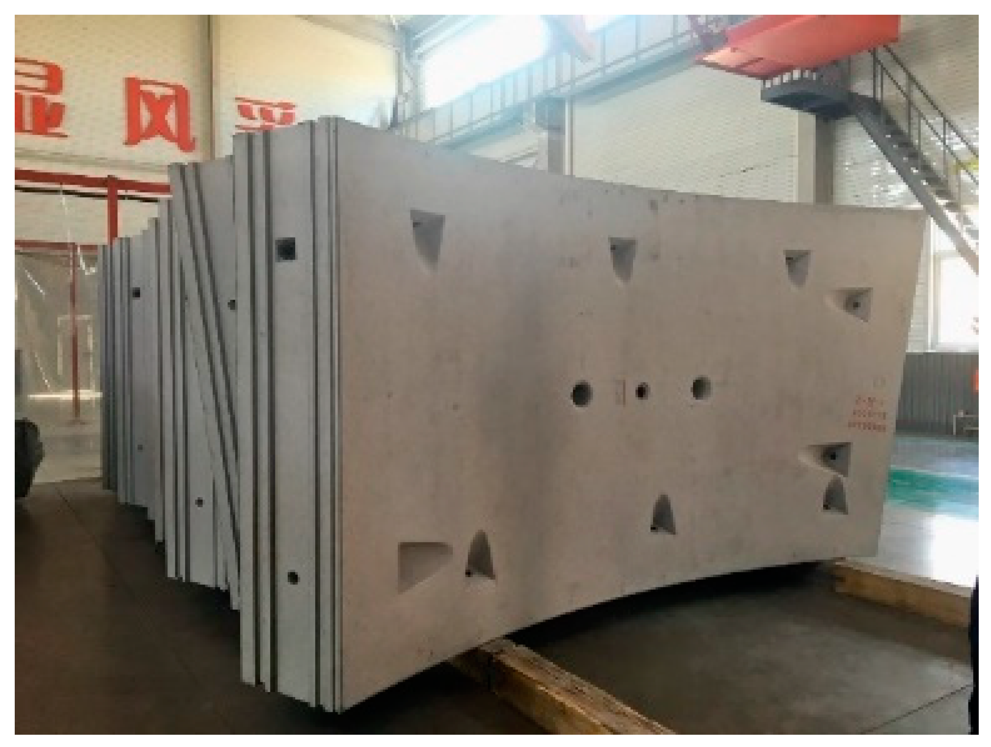
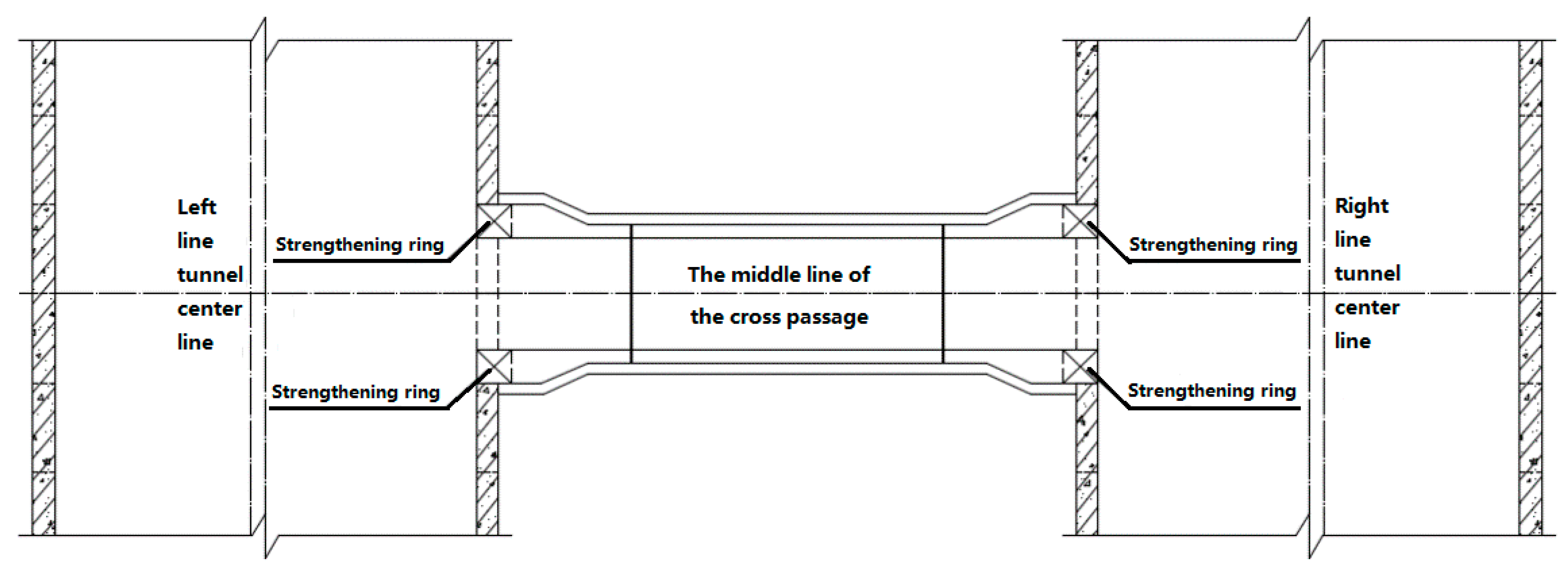
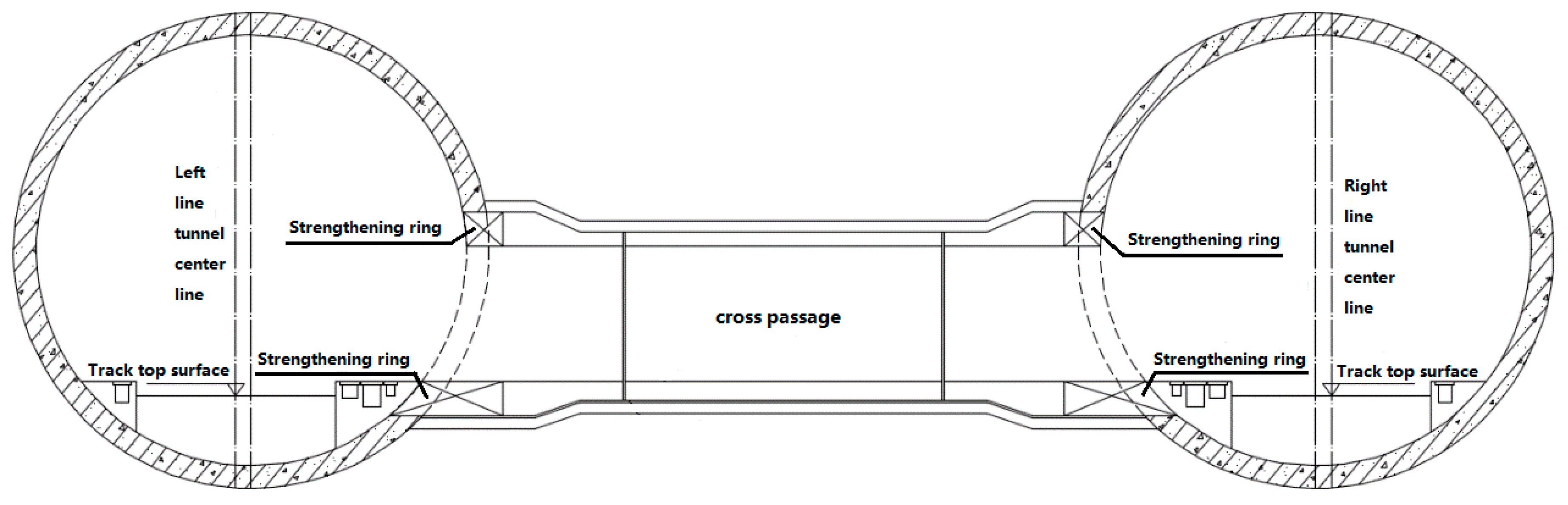
2. Project Overview
3. Numerical Analysis
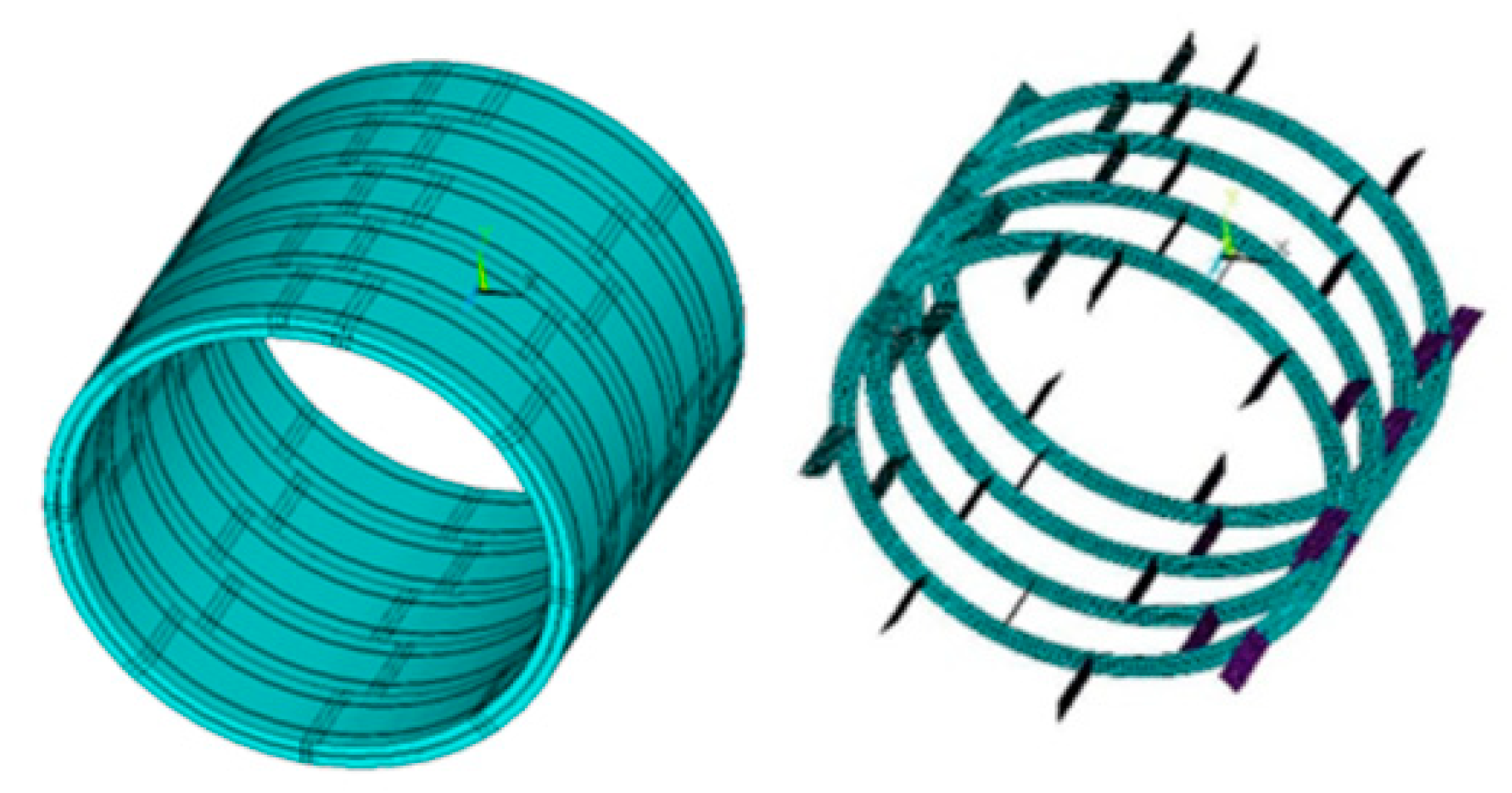
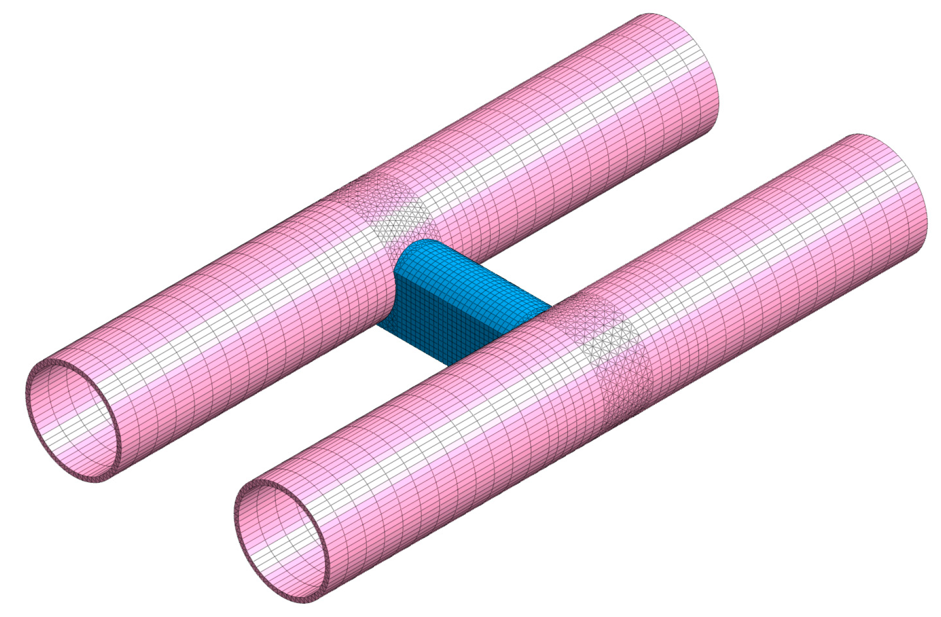
3.1. Numerical Model
3.2. Displacement and Stress Analysis of Segments in Shield Construction Process
3.2.1. Segment Displacement
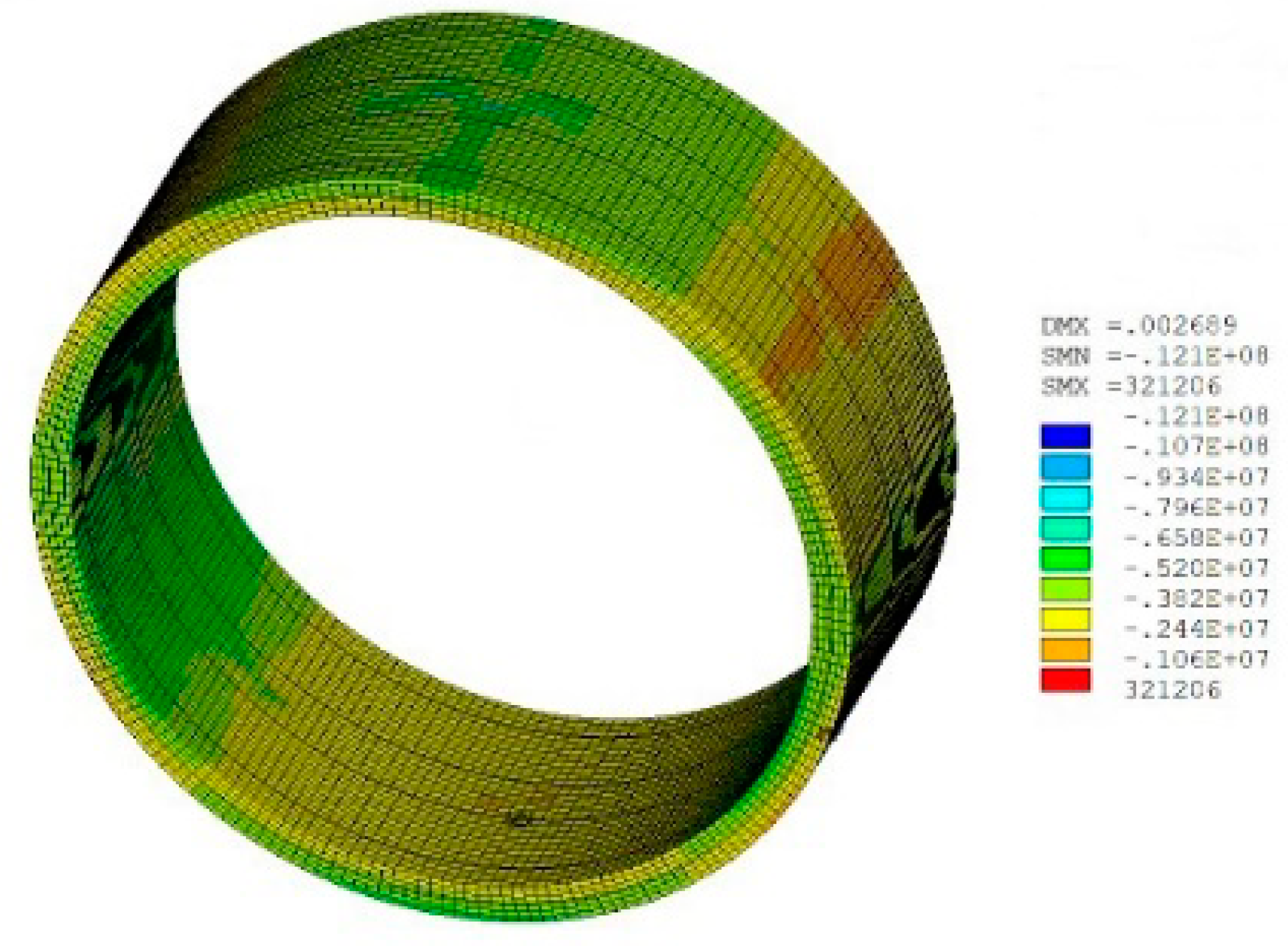
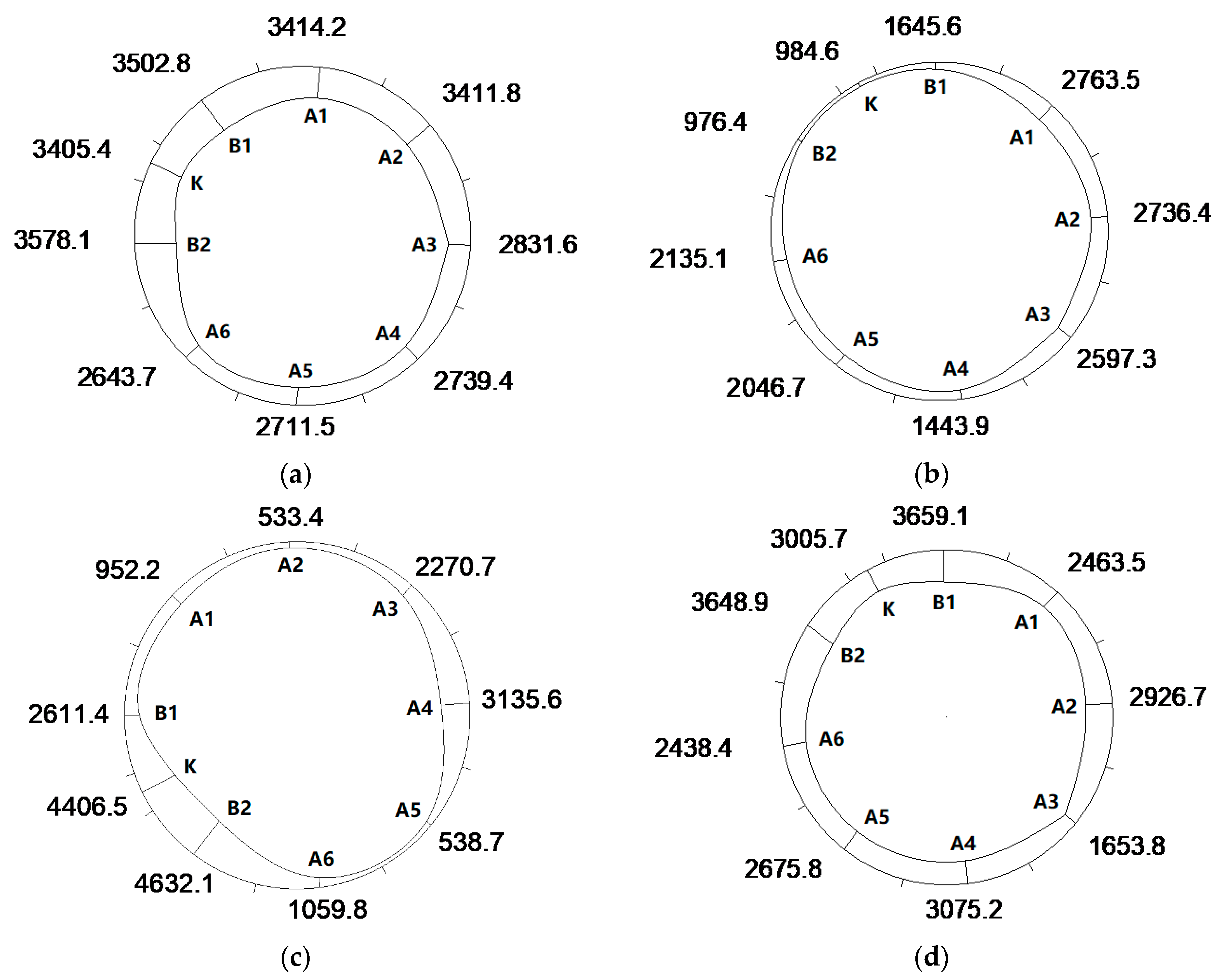
3.2.2. Segment Stress
3.2.3. Segment Internal Force
3.2.4. Bolt Stress
3.3. Displacement and Stress Analysis of Segments in Cross-Passage Construction Process
3.3.1. Segment Displacement
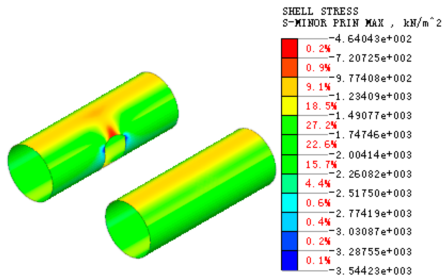
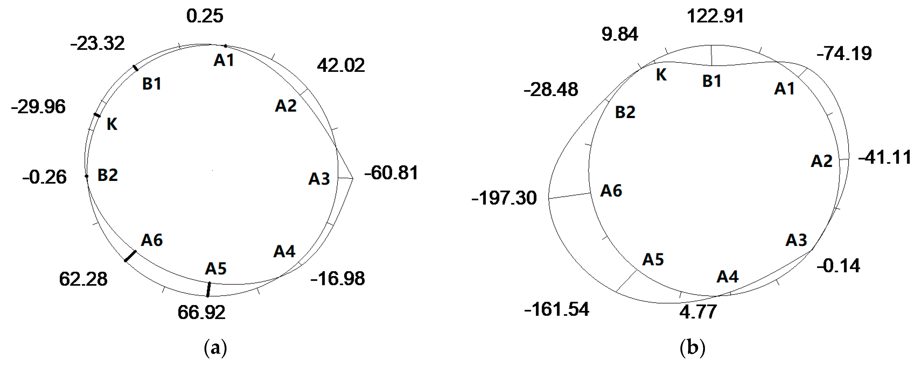
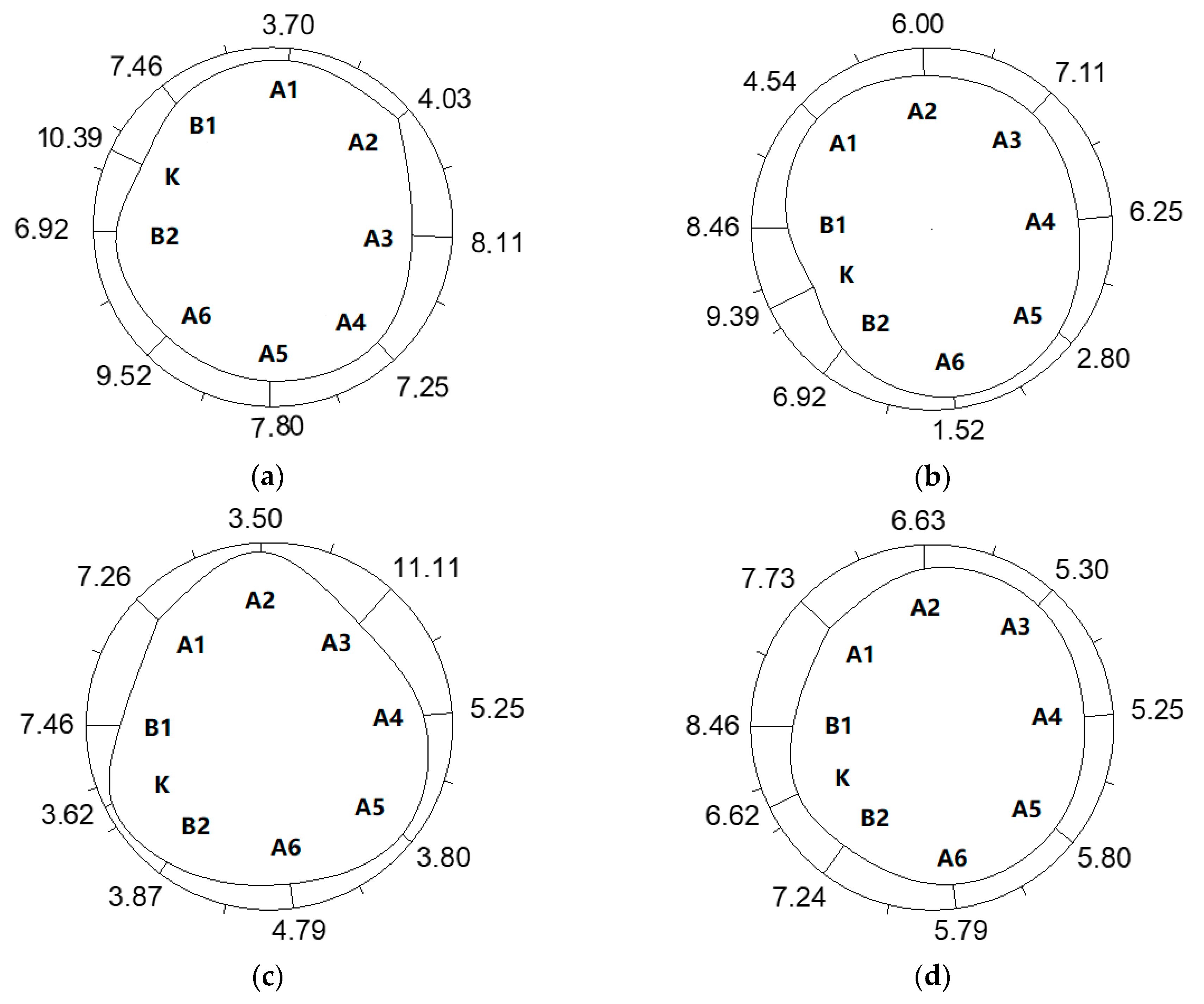
3.3.2. Segment Stress
- Maximum Principal Stress
- Minimum Principal Stress
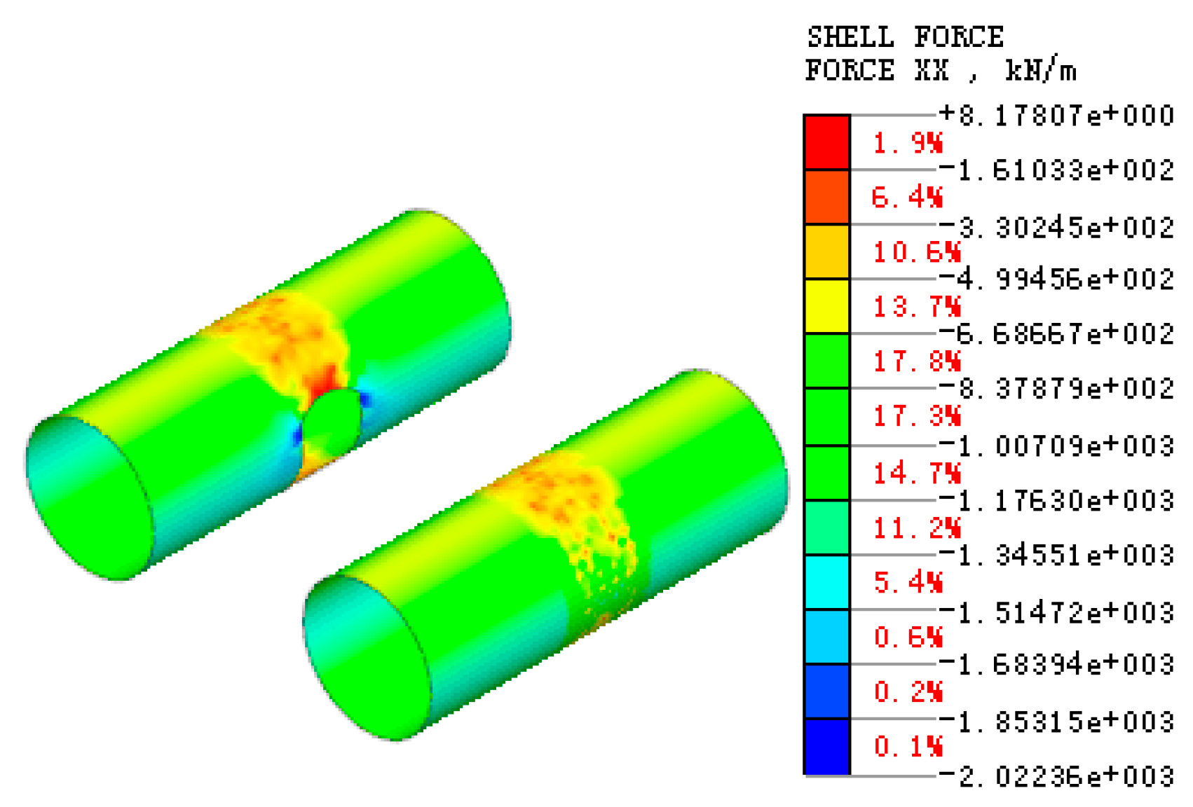
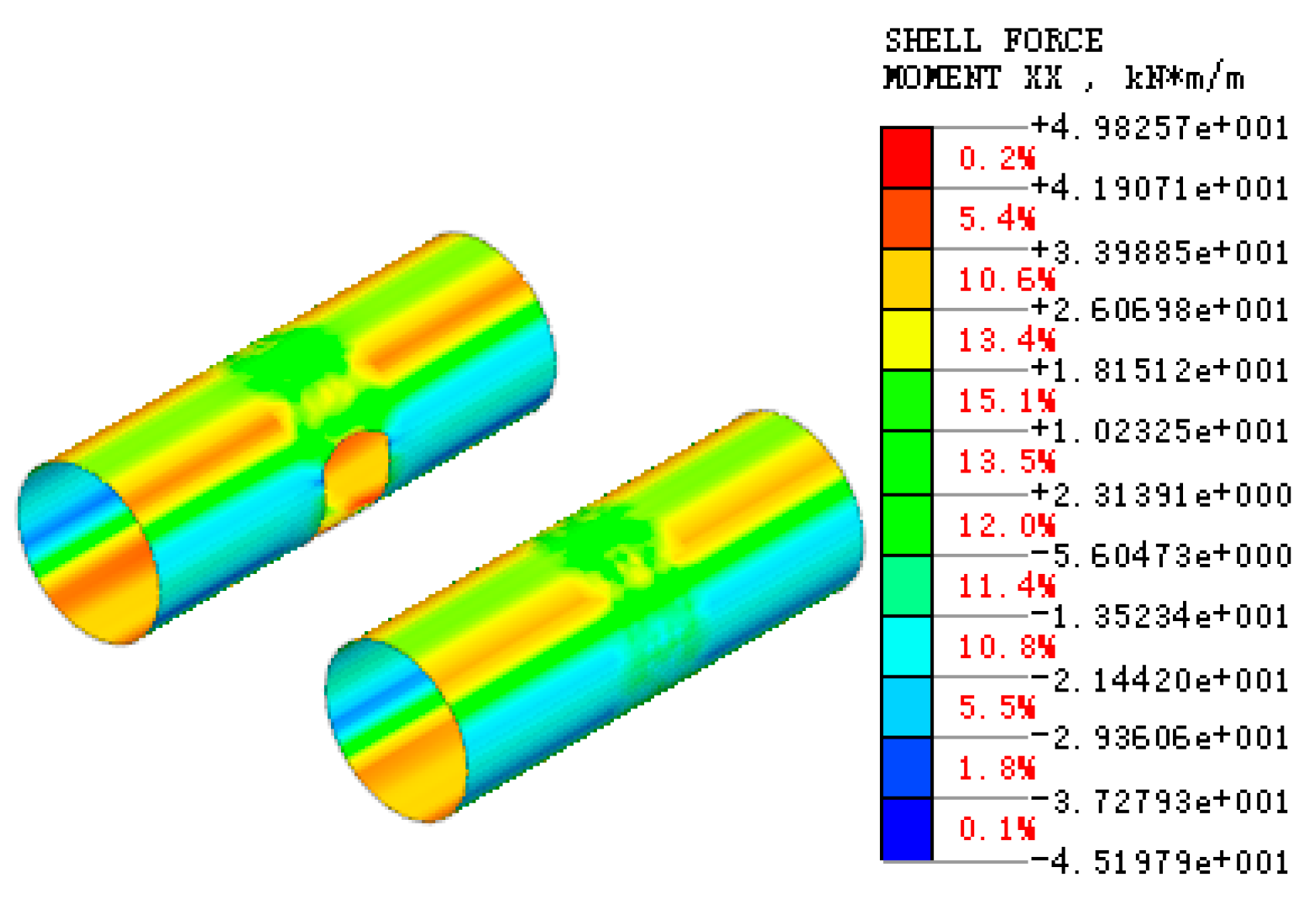
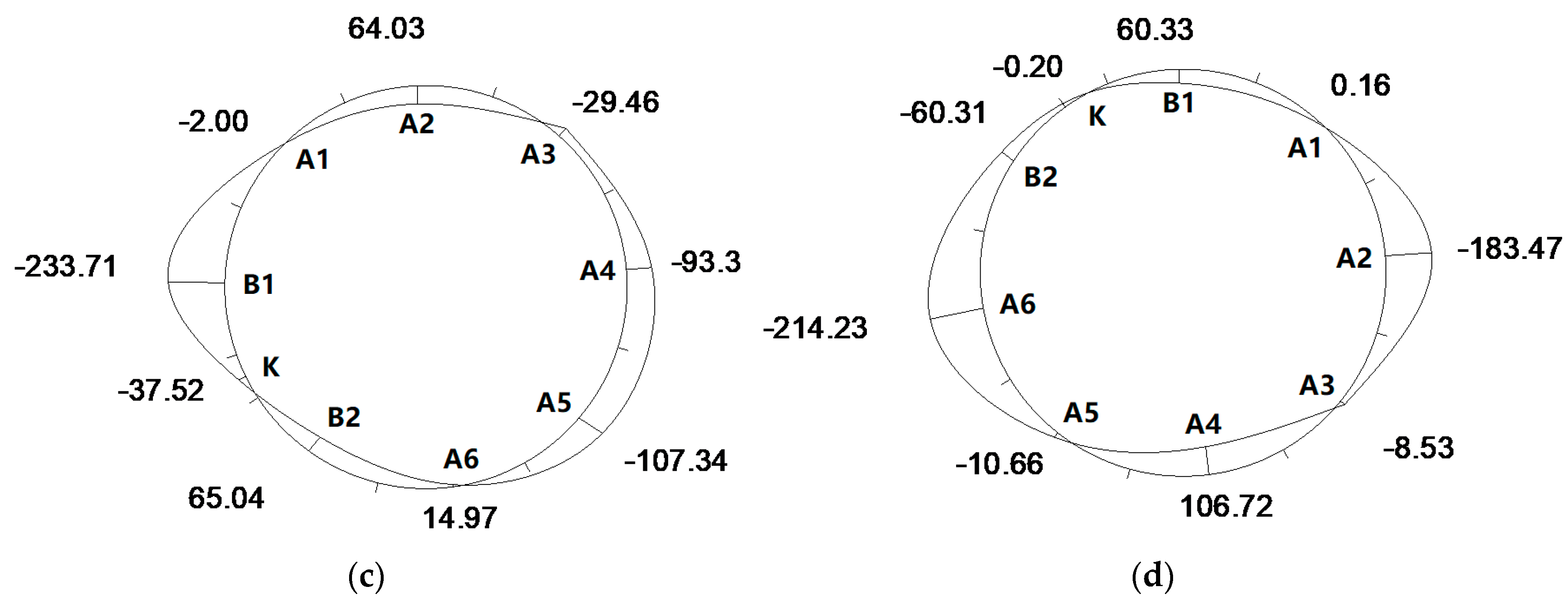
3.3.3. Segment Internal Force
- Axial Force
- Bending Moment
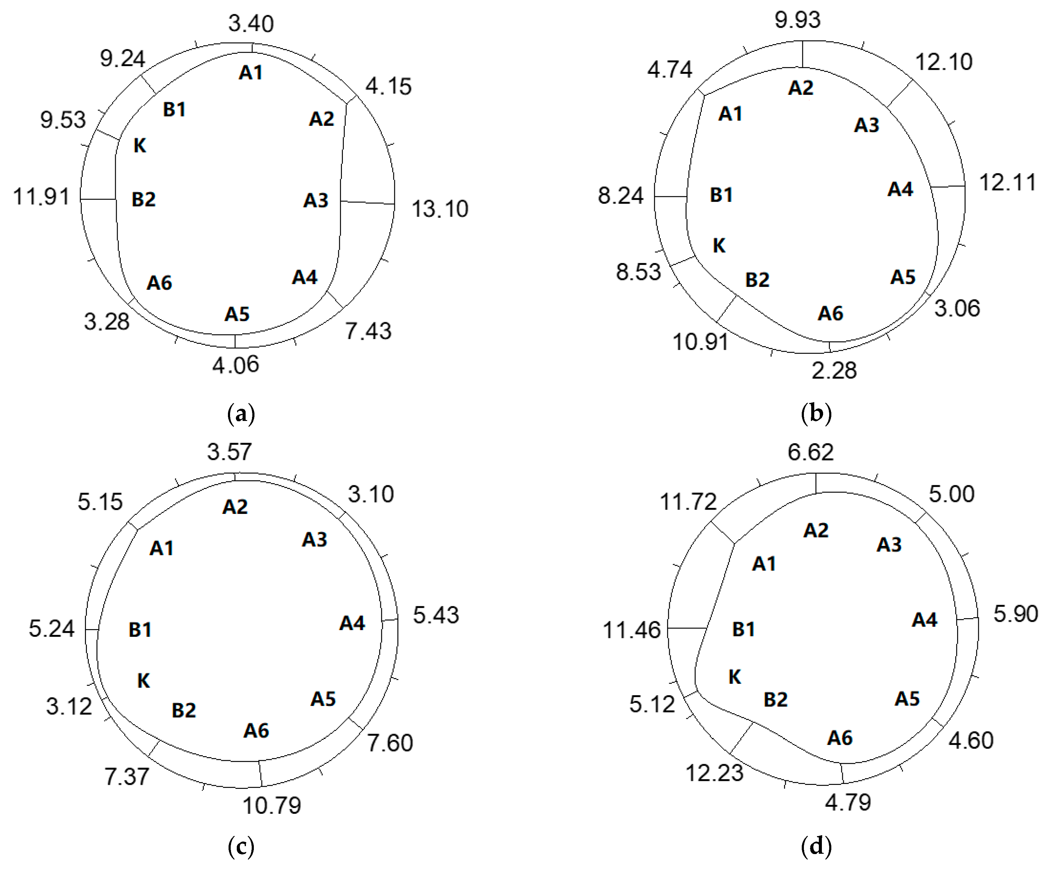
3.3.4. Bolt Stress
4. Field Test of Segment Stress during Shield Construction
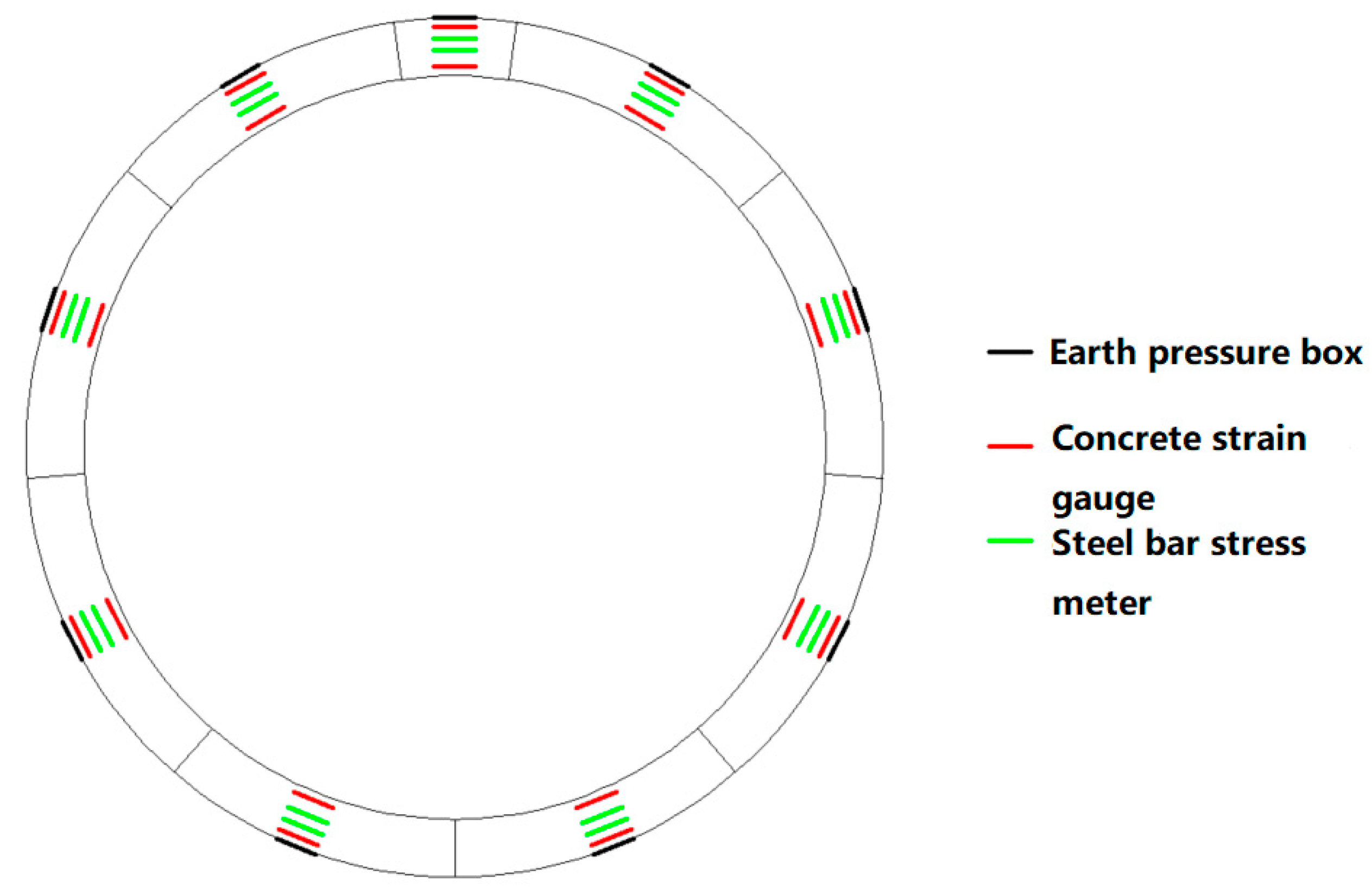
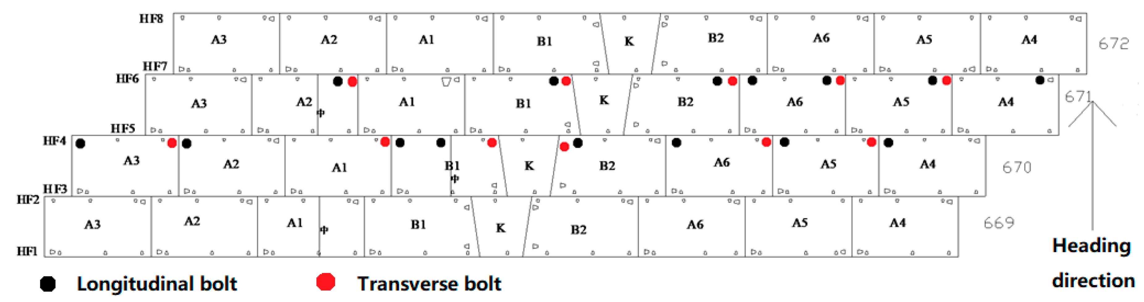
4.1. Scheme of Field Test
4.1.1. Segment Earth Pressure
4.1.2. Segment Internal Force
4.1.3. Internal Force of Bolts
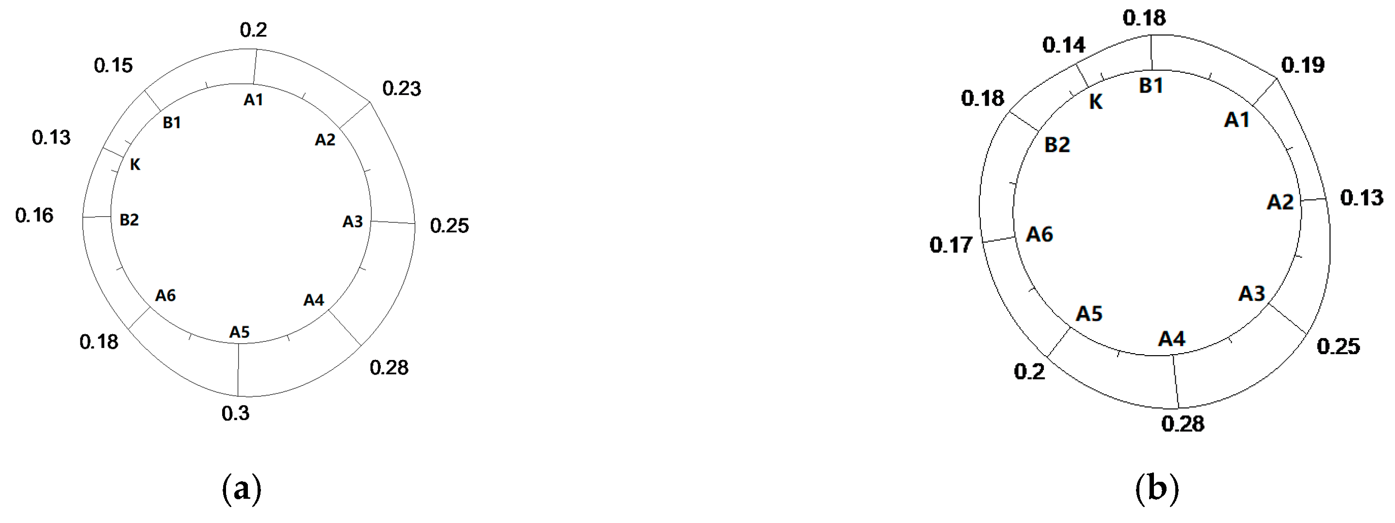
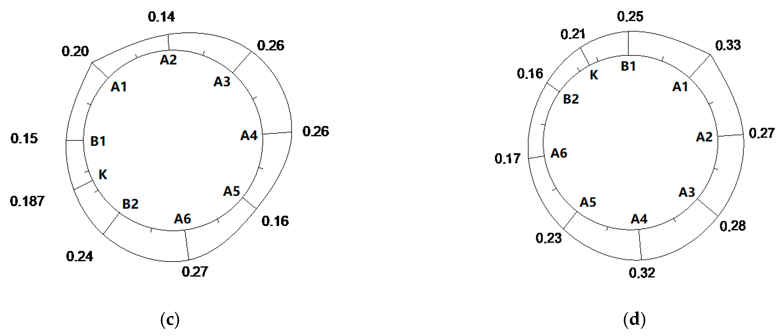
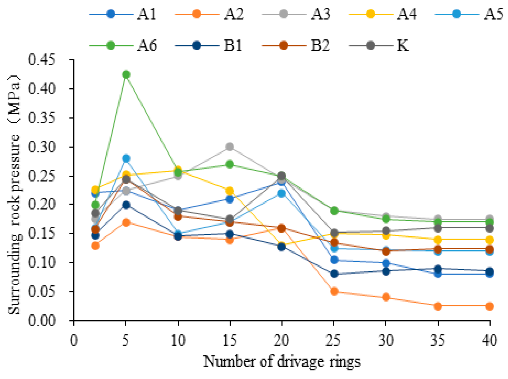
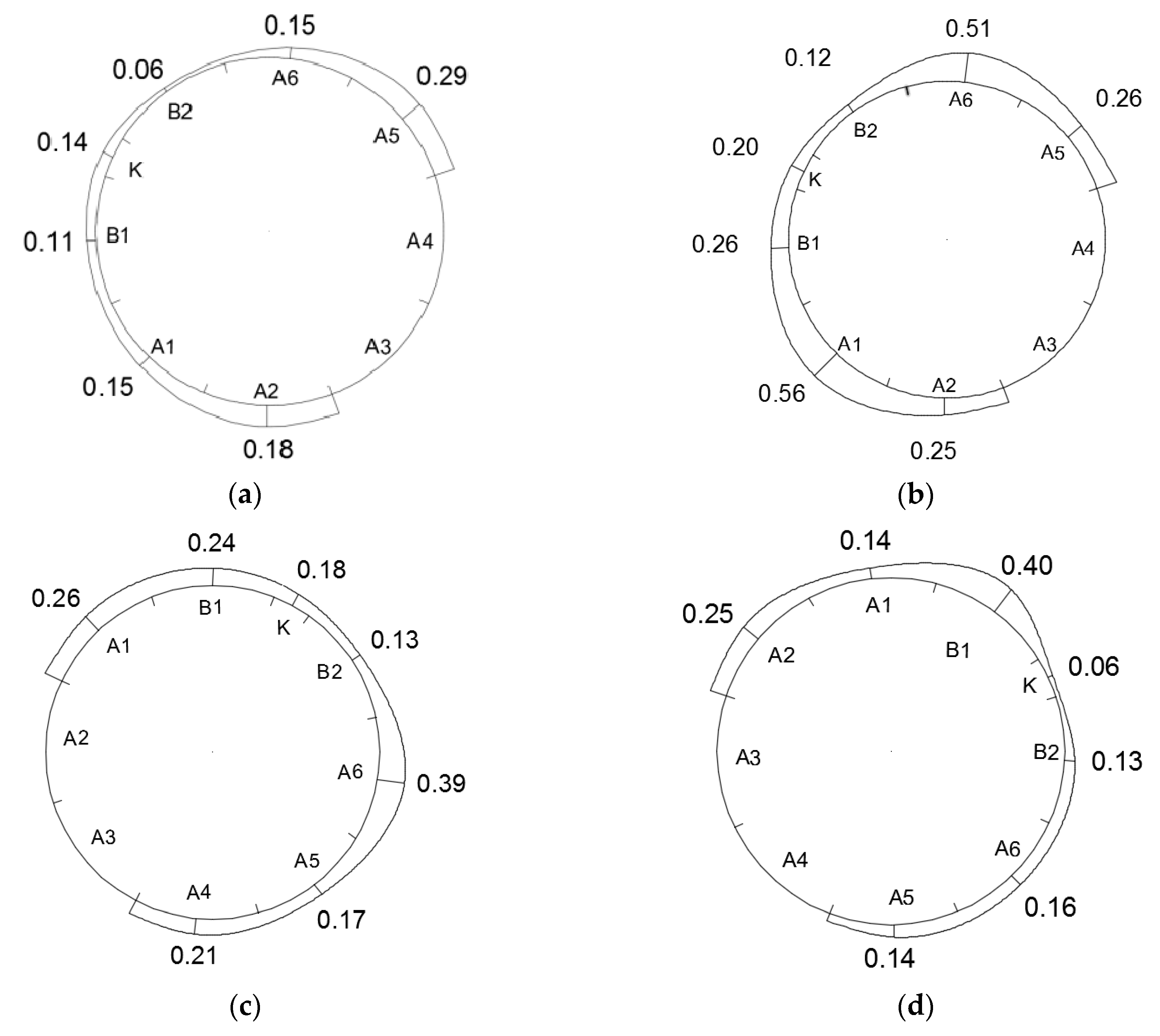
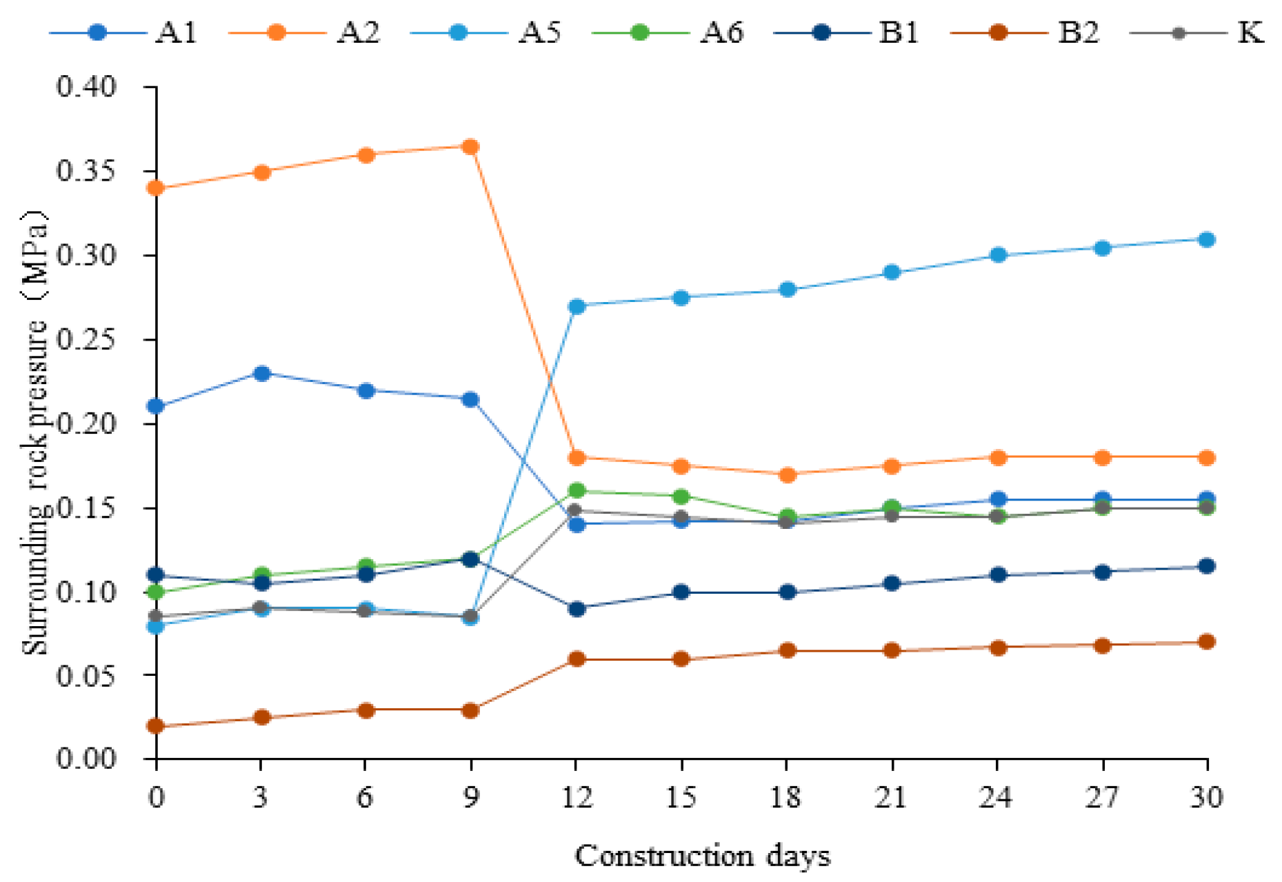
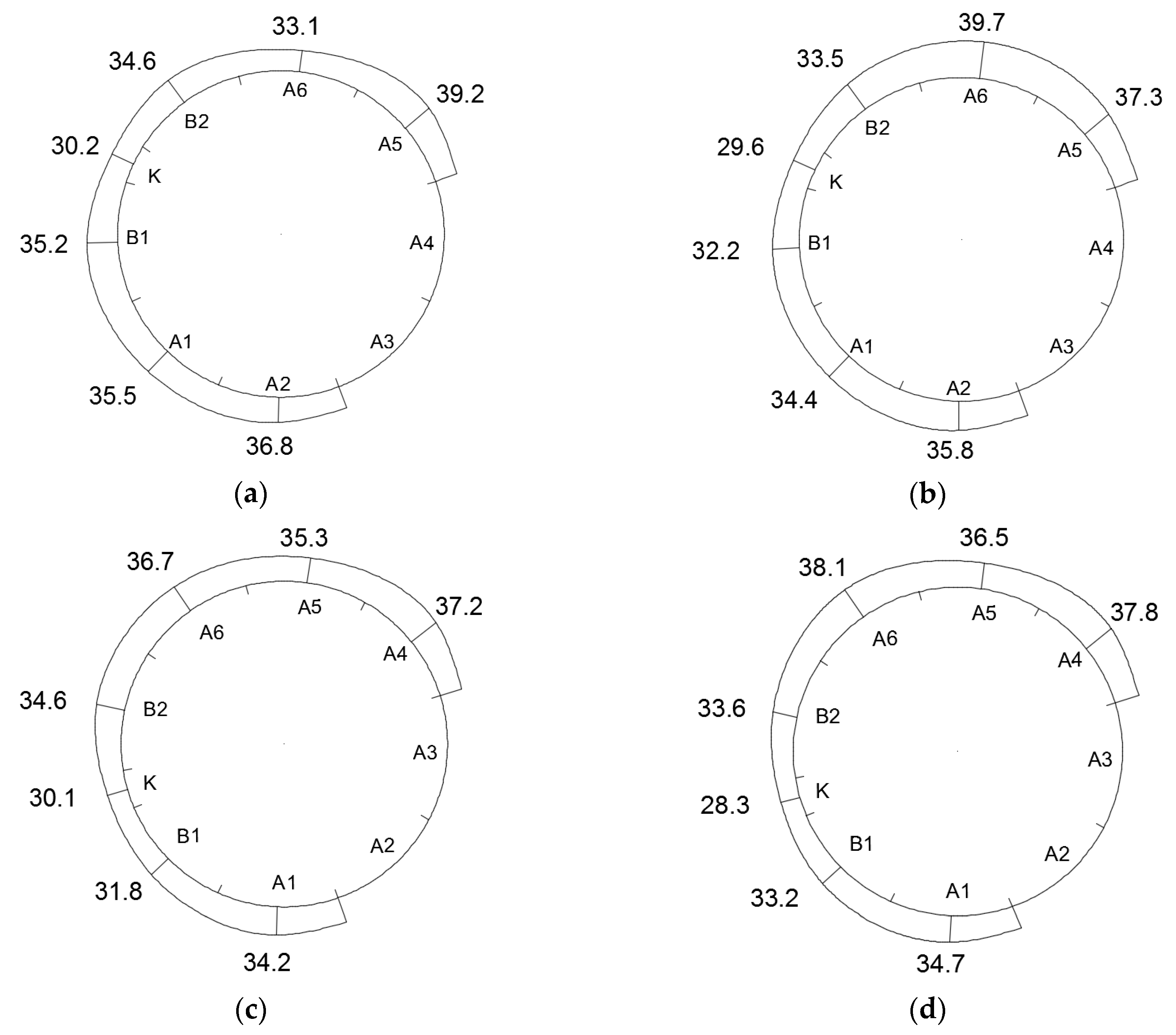
4.2. Surrounding Rock Pressure
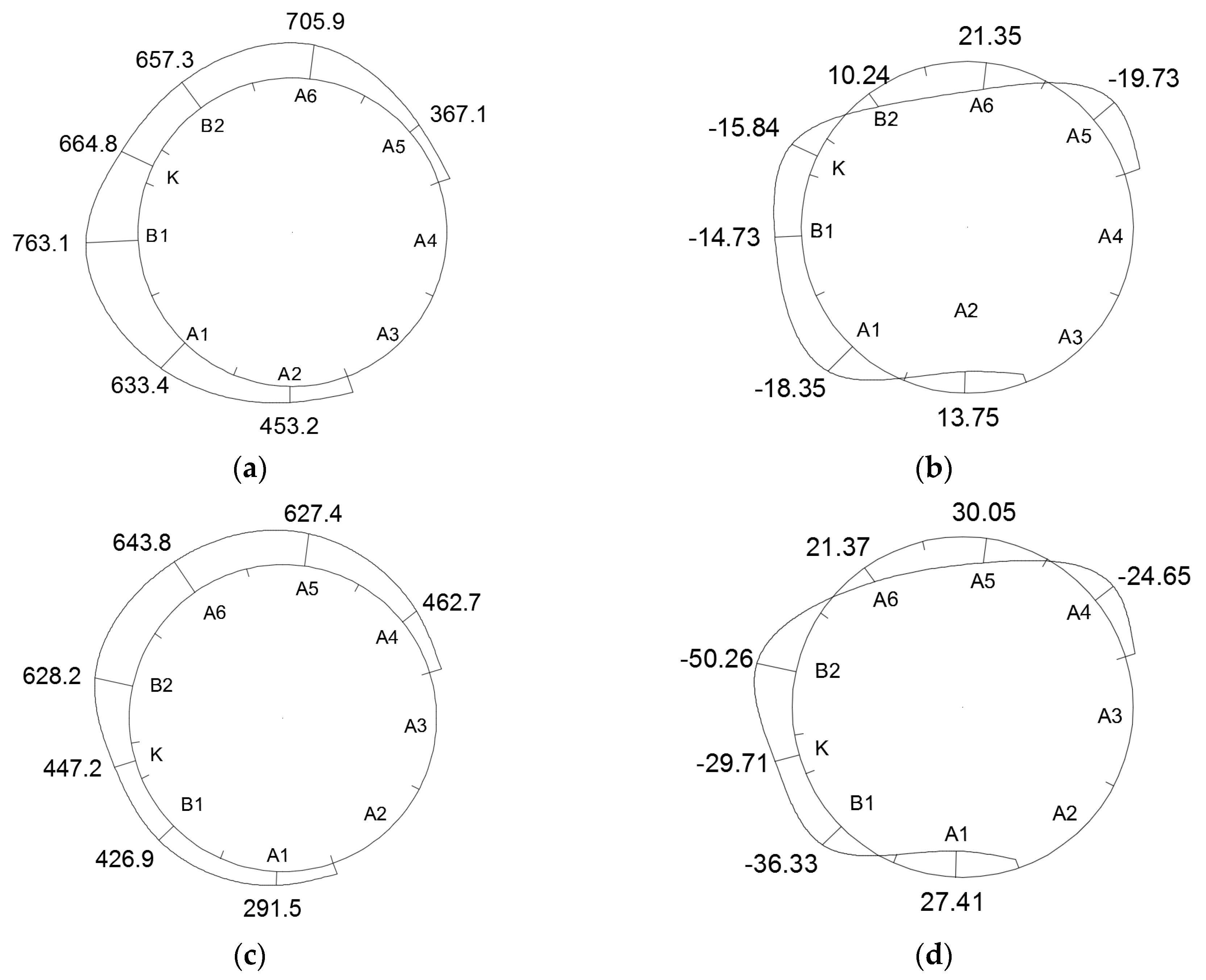
4.3. Internal Force of Segment
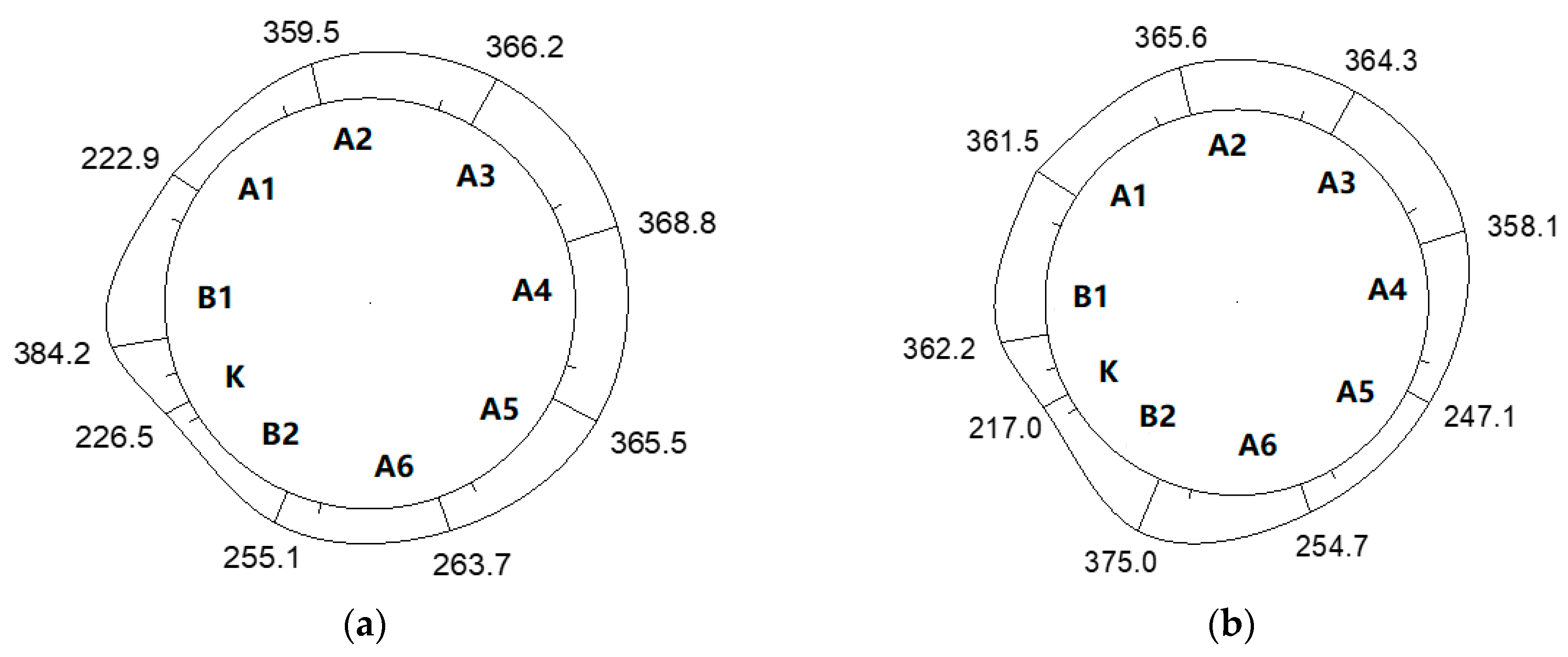
4.4. Steel Bar Force
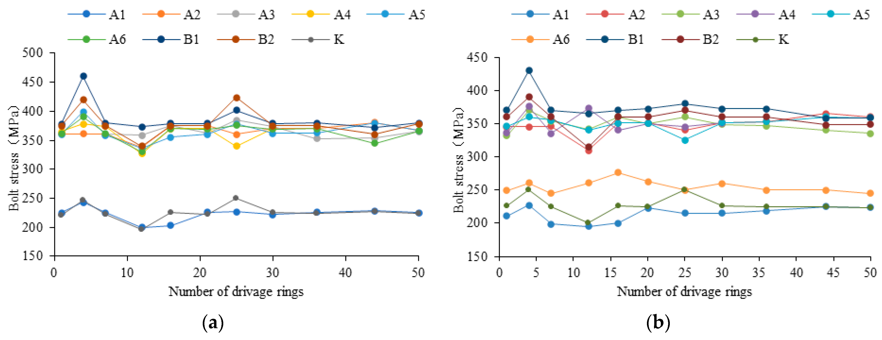
4.5. Bolt Stress
5. Field Test of Segment Stress during the Construction of the Cross-passage
5.1. Scheme of Field Test
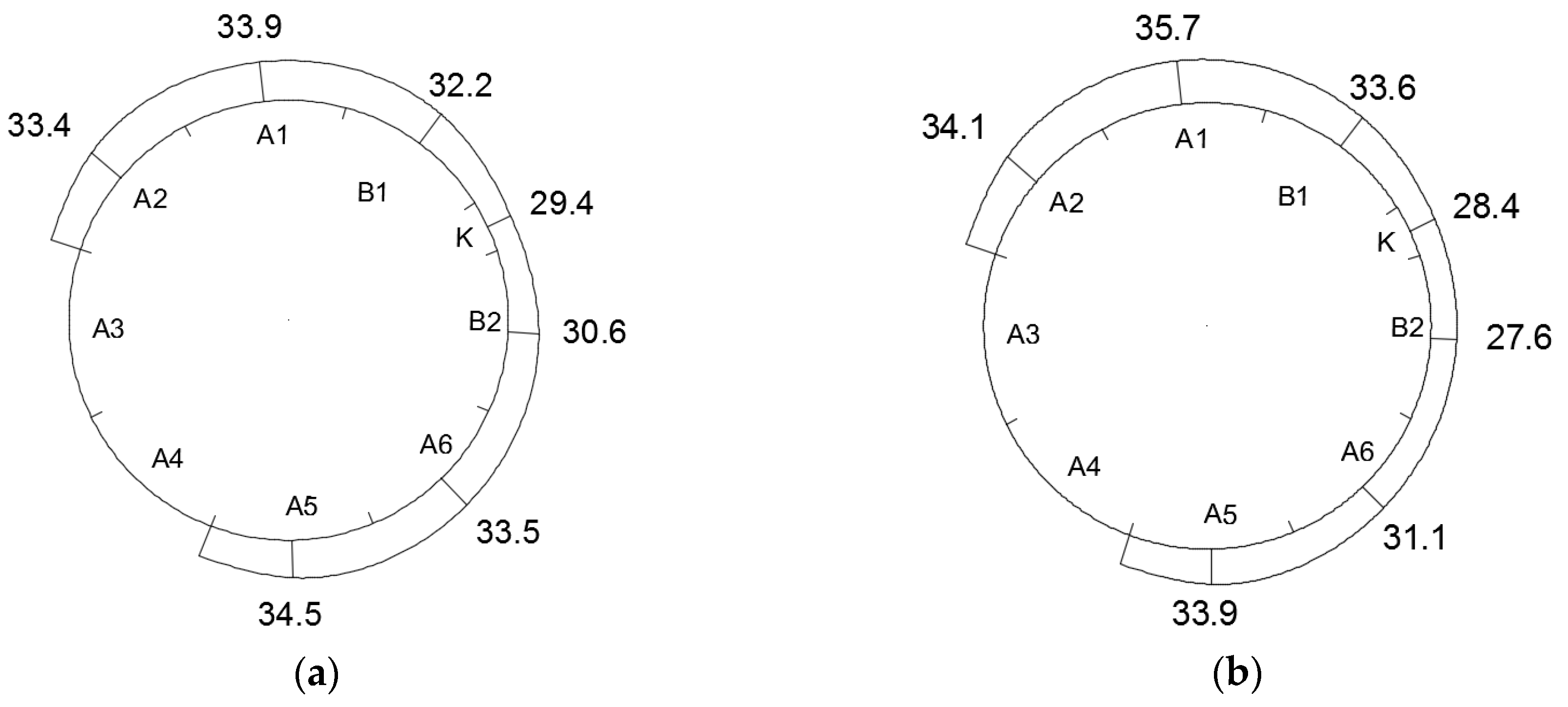
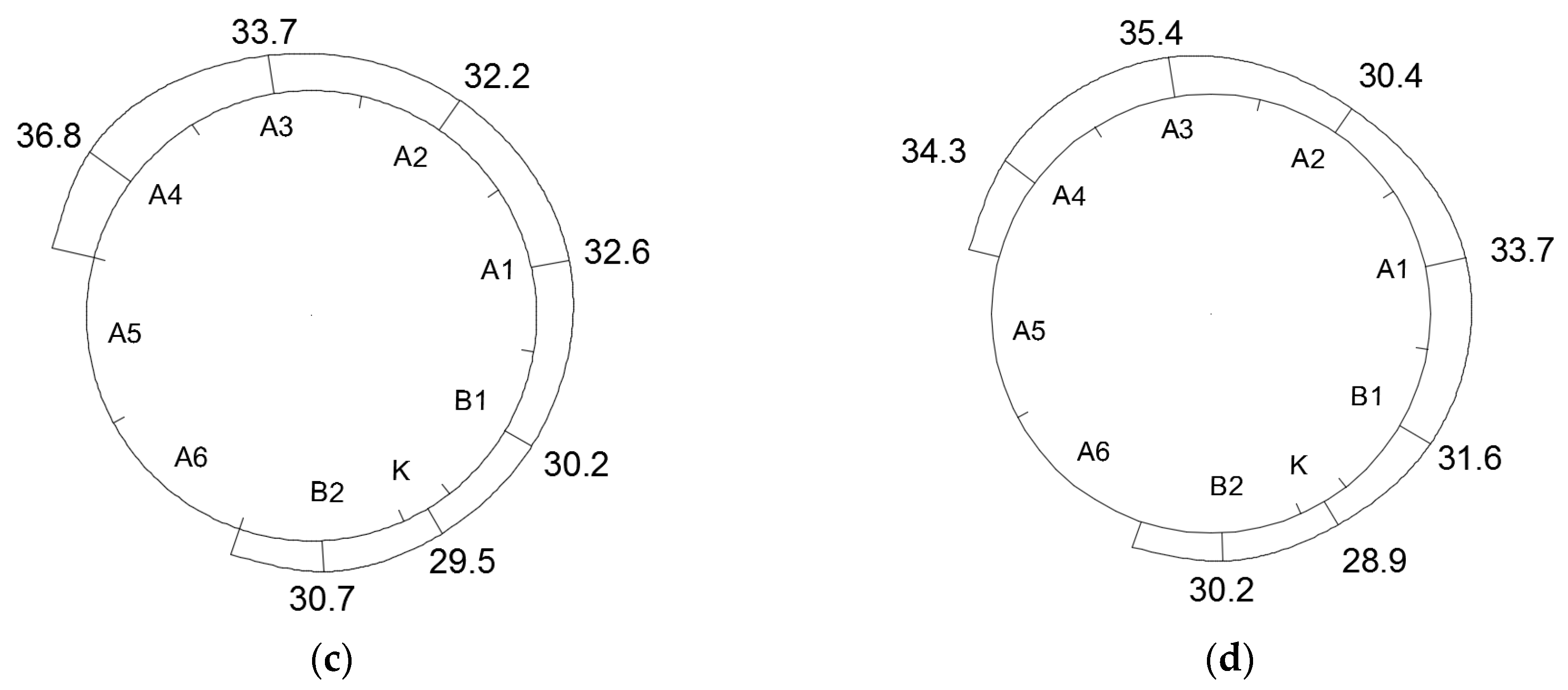
5.2. Surrounding Rock Pressure
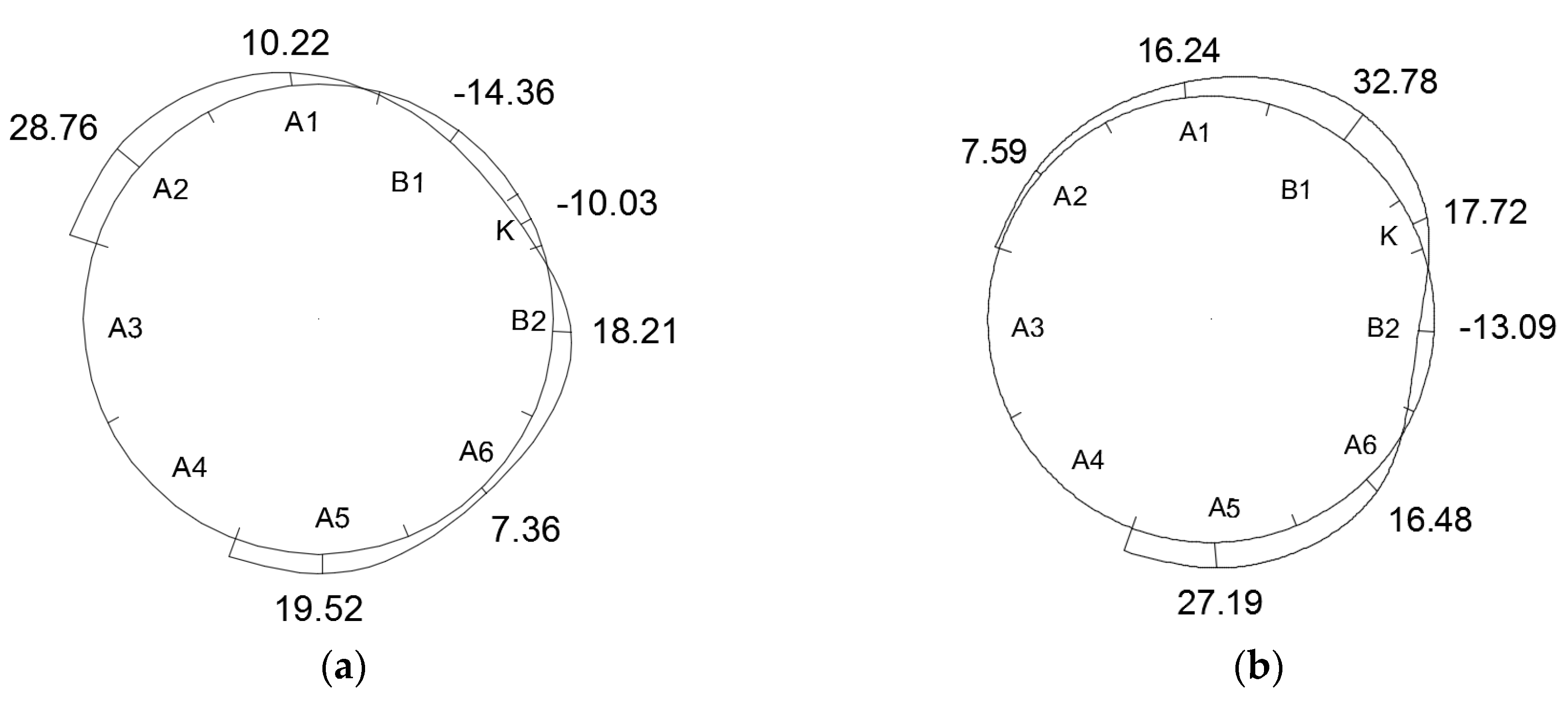
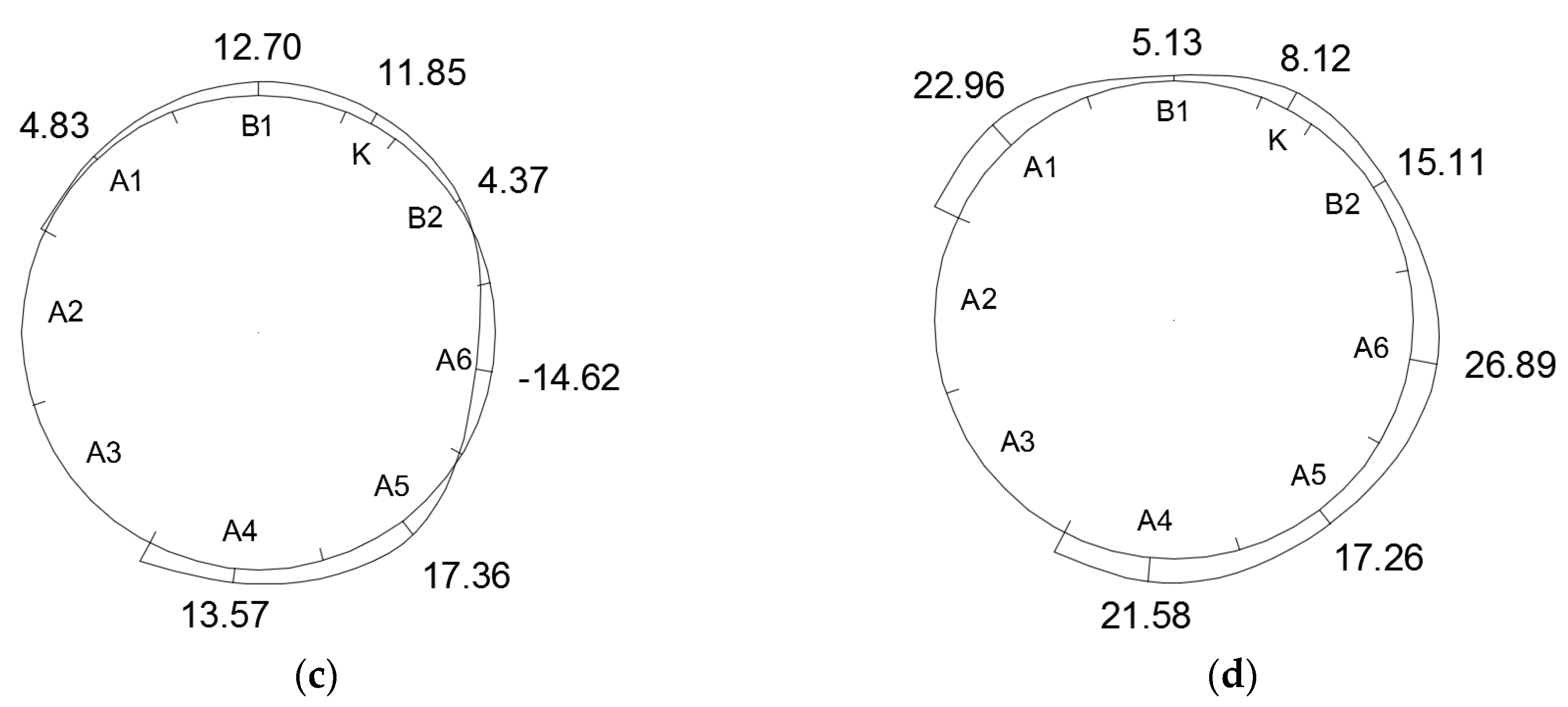
5.3. Internal Force of Segment
5.4. Steel Bar Force
5.5. Bolt Stress
6. Conclusions
- During the construction of a large-diameter shield tunnel, the segment ring may change elliptically: the vault and invert will produce inward displacement, the radial displacement of invert usually is more severe than that of the vault, and the outward displacement occurs at the waist on both sides of the arch.
- If near the K block, the mechanical performance of the segment is close to that of the hinge or chain rod, which can only effectively transfer the axial force but cannot resist the bending moment and shear force, so the joint has a noticeable weakening effect on the integrity of the segment.
- During the construction of the cross-passage, the maximum deformation and stress of the shield segment on the left and right lines may be symmetrically located at the interface of the main tunnel and the cross-passage. The upper and lower edge of the segment at the interface tends to change from compression to tension.
- During the construction of the cross-passage, the steel bars on the inside and outside of the segment vault and the arch waist might change from compressive stress to tensile stress, which can easily lead to segment damage, and these positions can be reinforced by erecting section steel frames before construction.
Author Contributions
Funding
Conflicts of Interest
References
- Ding, K.; Wang, Y. Analysis of segment internal forces of shield tunnel crossing underneath high speed railway. J. Mechatr. 2014, 2, 241–245. [Google Scholar] [CrossRef]
- Xiong, Q. Study on the Characteristics of Middle and Small Diameter Shield Tunnel. Master’s Thesis, South China University of Technology, Guangzhou, China, 2014. (In Chinese). [Google Scholar]
- Lu, D.Y. Analysis on Mechanical Characteristics and Cracking Phenomena of Segment Structure for Shield Tunnel during Construction Period. Ph.D. Thesis, Southwest Jiaotong University, Chengdu, China, 2019. (In Chinese). [Google Scholar]
- Li, Y.J.; He, P.; Qin, D.P. Stress analysis of metro shield tunnel segment—Based on 3D discontinuous contact computational model. Appl. Mech. Mater. 2011, 1446, 1828–1833. [Google Scholar] [CrossRef]
- Wang, F.; Cui, T.J. Numerical simulation on the stress and strain of lining structure with double shield tunnelling construction. Adv. Mater. Res. 2013, 2109, 2425–2429. [Google Scholar]
- Plizzari, G.A.; Tiberti, G. Steel fibers as reinforcement for precast tunnel segments. Tunn. Undergr. Space Technol. 2006, 21, 438–439. [Google Scholar] [CrossRef]
- Gruebl, F. Segmental Ring Design (New Challenges with High Tunnel Diameters). In Proceedings of the World Tunnel Congress 2012, Bangkok, Thailand, 20–23 May 2012. [Google Scholar]
- Sun, J.S.; Guo, H.J. Shell-spring calculation model for segment lining of shield tunnels. Chin. J. Undergr. Space Eng. 2019, 15, 1048–1054. [Google Scholar]
- Wang, T.; Shi, B.; Zhu, Y. Structural Monitoring and Performance Assessment of Shield Tunnels during the Operation Period, Based on Distributed Optical-Fiber Sensors. Symmetry 2019, 11, 940. [Google Scholar] [CrossRef] [Green Version]
- Wang, X.; Shi, B.; Wei, G.; Chen, S.-E.; Zhu, H.; Wang, T. Monitoring the behavior of segment joints in a shield tunnel using distributed fiber optic sensors. Struct. Control. Heal. Monit. 2017, 25, e2056. [Google Scholar] [CrossRef] [Green Version]
- Mi, B.; Xiang, Y. Analysis of the Limit Support Pressure of a Shallow Shield Tunnel in Sandy Soil Considering the Influence of Seepage. Symmetry 2020, 12, 1023. [Google Scholar] [CrossRef]
- Wang, L.; Han, K.; Xie, T.; Luo, J. Calculation of Limit Support Pressure for EPB Shield Tunnel Face in Water-Rich Sand. Symmetry 2019, 11, 1102. [Google Scholar] [CrossRef] [Green Version]
- Li, Z.L.; Wright, P.; Soga, K. Three-dimensional finite element analysis of the behaviour of cross passage between cast-iron tunnels. Can. Geotech. J. 2016, 53, 930–945. [Google Scholar] [CrossRef] [Green Version]
- Yue, F.T.; Qiu, P.Y.; Yang, G.X.; Ding, G.Y.; Zhang, Y. Numerical calculation of tunnel cross-passage construction underneath river. J. China Coal. Soc. 2005, 30, 710–714. [Google Scholar]
- Xu, Y.Q. Study on Force and Deformation Regularity of Tunnel Lining Structure Using Divided-Period Freezing Construction in Long-Distance Connecting Aisle. Master’s Thesis, China University of Mining and Technology, Xuzhou, China, 2015. (In Chinese). [Google Scholar]
- Yin, Y. Study on the Influence of Freezing Method Construction on Tunnel and Ground Surface with the Connected Aisle of Great Height Difference. Master’s Thesis, China University of Mining and Technology, Xuzhou, China, 2018. (In Chinese). [Google Scholar]
- Wang, L. The Mechanical Behavior Study of Intersecting Segment of Shield Tunnel and Cross-Passage. Master’s Thesis, Shijiazhuang Tiedao University, Shijiazhuang, China, 2018. (In Chinese). [Google Scholar]
- Guan, Q. Study on Force and Deformation Law of Lining Structure in Freezing Construction for Contacting Passage of Through-River Tunnel. Master’s Thesis, China University of Mining and Technology, Xuzhou, China, 2014. (In Chinese). [Google Scholar]
- Lv, H. Study on Construction Mechanics for Cross-Passage of Tunnel. Master’s Thesis, Tongji University, Shanghai, China, 2006. (In Chinese). [Google Scholar]
- Oggeri, C.; Ova, G. Quality in tunnelling: ITA-AITES Working Group 16 Final report. Tunn. Undergr. Space Technol. 2004, 19, 239–272. [Google Scholar] [CrossRef]


| Material Type | Heavy Degree (kN/m3) | Elastic Modulus (MPa) | Poisson’s Ratio | Cohesion (kPa) | Friction Angle(°) |
|---|---|---|---|---|---|
| Silty clay | 18.3 | 14.1 | 0.3 | 36.5 | 10 |
| Fine sand | 20.7 | 19.5 | 0.3 | - | - |
| Silt sand | 19.5 | 50 | 0.25 | - | - |
| Shield segment | 25 | 30,000 | 0.17 | - | - |
| Grouting body | 22 | 800 | 0.32 | 90 | 36 |
| Initial support | 23 | 21,000 | 0.3 | - | - |
| Secondary lining | 25 | 30,000 | 0.15 | - | - |
| Project | Tensile Stress | Position |
|---|---|---|
| Maximum value (MPa) | 56.5 | Connecting bolts for A4 and A5 |
| Minimum value (MPa) | 34.5 | Connecting bolts for A1 and B1 |
| Project | Tensile Stress | Position |
|---|---|---|
| Maximum value (MPa) | 67.8 | Segment bottom |
| Minimum value (MPa) | 9.2 | Interface position side edge |
© 2020 by the authors. Licensee MDPI, Basel, Switzerland. This article is an open access article distributed under the terms and conditions of the Creative Commons Attribution (CC BY) license (http://creativecommons.org/licenses/by/4.0/).
Share and Cite
Tan, Z.; Li, Z.; Tang, W.; Chen, X.; Duan, J. Research on Stress Characteristics of Segment Structure during the Construction of the Large-Diameter Shield Tunnel and Cross-Passage. Symmetry 2020, 12, 1246. https://doi.org/10.3390/sym12081246
Tan Z, Li Z, Tang W, Chen X, Duan J. Research on Stress Characteristics of Segment Structure during the Construction of the Large-Diameter Shield Tunnel and Cross-Passage. Symmetry. 2020; 12(8):1246. https://doi.org/10.3390/sym12081246
Chicago/Turabian StyleTan, Zhongsheng, Zonglin Li, Wei Tang, Xueying Chen, and Junmeng Duan. 2020. "Research on Stress Characteristics of Segment Structure during the Construction of the Large-Diameter Shield Tunnel and Cross-Passage" Symmetry 12, no. 8: 1246. https://doi.org/10.3390/sym12081246