The Effect of Recrystallization on Creep Properties of Alloy IN939 Fabricated by Selective Laser Melting Process


Department of Mechanical Systems Engineering, Tokyo Metropolitan University, 1-1 Minami-Osawa, Hachioji-City, Tokyo 192-0397, Japan
*
Authors to whom correspondence should be addressed.
Metals 2020, 10(8), 1016; https://doi.org/10.3390/met10081016
Submission received: 30 June 2020
/
Revised: 20 July 2020
/
Accepted: 25 July 2020
/
Published: 28 July 2020
(This article belongs to the Special Issue Advances in Superalloys and High Temperature Intermetallics)
Abstract
:In this research, we studied the creep properties of a selective laser melting (SLM)-processed γ′-strengthened IN939 superalloy along the building direction compared to a conventional cast alloy as a reference specimen. In the as-built condition, high-density dislocations were formed as a result of the SLM process due to the generation of the larger thermal gradient. Post-heat treatment was necessary to obtain specific mechanical properties to match industrial requirements. Two heat treatment conditions were used: the first was lower temperature heat treatment (LTH: solution treatment at 1160 °C/4 h + aging at 850 °C/16 h). The second was higher temperature heat treatment (HTH: solution treatment at 1240 °C/6 h + aging at 850 °C/16 h). Creep tests were conducted at 816 °C/250 MPa. The first and second heat treatment conditions were used for the SLM specimens, but only the first condition was used for the cast alloy (cast-LTH). The SLM specimens in the as-built and LTH conditions showed very poor creep life but good elongation. The poor creep life of the as-built specimen was caused by high dislocation density and the small recrystallized grains formed during testing. In the LTH specimen, poor creep life was due to the formation of the undesirable η phase at the grain boundary, as well as the formation of small recrystallized grains during testing. The creep life of the HTH specimen was 2.7 times longer compared to the LTH specimen. This was because these specimens were covered with recrystallized grains that included low-density dislocations, columnar grain morphology with random orientation, improvement in γ′ precipitate size, and elimination of undesirable η phase. The cast LTH specimen showed longer creep life than SLM specimens because of coarser grains with low-density dislocations, γ′ precipitate coarsening during the creep, and the presence of carbides at grain boundaries. In addition, the cast LTH specimen exhibited lower creep strain rate than SLM specimens also helped in creep life improvement.
1. Introduction
Ni-based superalloys are widely used in aircraft engines and power generation industries because of their excellent properties like tensile, creep, fatigue, corrosion, and also oxidation resistance at extremely higher temperatures (~850 °C) [1]. To obtain these properties at higher temperatures material should survive without failure for a certain period. The conventional cast process is complex and cost-oriented to make intricate shapes like turbine blades in aerospace industries. In addition, this process results in macro segregation due to melt-related problems such as porosity and segregation, which degrade mechanical properties [2]. To overcome this problem a new technology should be designed and developed. The only way to mitigate this problem is through rapid solidification of metal or use of a solid-state sintering process or additive manufacturing process.
Additive manufacturing (AM) technology, also known as 3D printing or rapid prototyping, has gained attention in recent years in various industries including aerospace and automotive. Among various processing methods, the selective laser melting (SLM) process has good features for the AM of nickel-based superalloys. It melts the powder layer by layer with high laser power, resulting in large thermal residual stresses within the parts. Additive manufacturing technology has already been studied and put to practical use in various materials such as stainless steel [3,4,5,6], Ti-based alloys [7,8,9,10], TiAl alloys [11,12,13], and Ni-based superalloys [14,15,16,17].
For high-temperature applications, IN718 is the most commonly used material due to its excellent mechanical properties owing to primary strengthening phases γ″ and γ′. However, the γ″ precipitate is a metastable phase and transforms in to δ (γ″ → δ) above 650 °C [18]. Furthermore, for applications at higher temperatures other alloys are required. One such material is Inconel 939 which is widely studied in the cast and wrought conditions [19]. It is a high-chromium alloy with good mechanical properties and is capable of operating at temperatures up to 850 °C [20].
γ′-Precipitation-hardened Ni-based superalloy IN939 was developed in the late 1960s to meet industrial requirements on mechanical properties, oxidation, and corrosion resistance at temperatures up to 850 °C [21,22,23]. IN939 has been widely used in aircraft engine components that experience intense heat, including gas turbine blades, vanes, fuel nozzles, diffusers, etc. [24]. There are very few studies that have been done on AM of IN939. Kanagarajah et al. studied a SLM-processed IN939 that showed a columnar-grained structure, which led to superior tensile and fatigue properties compared to conventional materials cast at room temperature and 750 °C [22]. Philpott et al. showed the effect of conventional heat treatment on microstructures of the cast and SLM-processed materials [25]. However, in the previous study, only the effect of heat treatment on the microstructure was studied; they did not address the creep property, which is an important characteristic of Ni-based superalloys.
In this study, we consider the effect of heat treatment on the microstructure and creep characteristics of the SLM-processed IN939 alloy at the practical temperature of 816 °C. Solution and aging heat treatments were conducted on SLM-processed materials. The solution heat treatment was done at 1160 °C and 1240 °C, followed by aging heat treatment at 850 °C/16 h/AC. The microstructural and creep properties were studied. The solution heat treatment at 1160 °C/4 h was used to homogenize the microstructure, while the solution heat treatment at 1240 °C was used to get the fully recrystallized grains, which will prevent the recrystallization during heat treatment and creep.
2. Materials and Methods
A batch of gas-atomized IN939 powder (EOS Nickel Alloy IN939) was used as test material for the SLM process; its typical chemical composition is given in Table 1. A block with dimensions of 45 × 45 × 45 mm3 was built by the EOS M290 SLM machine (EOSINT M290; EOS, Robert-Stirling-Ring 1, 82152, Krailling, Bavaria, Germany) in a protective argon atmosphere. The SLM IN939 block was separated from the base plate and sliced into thin plates (3.1 mm thick) by using an electro-discharge wire cutting machine (Brother HS-300, Tokyo, Japan) and creep specimens were cut from the plates.
A conventionally cast IN939 alloy was used as the reference material. Two kinds of heat treatments were conducted in this study. In the first condition, solution heat treatment was performed at 1160 °C/4 h in an Ar atmosphere (homogenization of γ matrix, dissolution of γ′ and η phases), followed by furnace cooling (FC), an aging heat treatment at 850 °C/16 h, and then air-cooling (AC) (for growth of primary γ′ precipitate and carbides). In the second condition, solution treatment was conducted at 1240 °C/6 h/FC (the aim is to eliminate residual stresses and to improve grain size which is beneficial for good creep properties), followed by aging heat treatment at 850 °C/16 h/AC. The first and second condition heat treatments were used for SLM specimens; however, in the case of the cast IN939 alloy, only the first heat treatment condition was used, as shown in Table 2.
Microstructural evolution observations were carried out with a scanning electron microscope (SEM) and transmission electron microscope (TEM). Electro-discharge (ED) wire cutting was used to cut SEM specimens for microstructure observation. The surface was ground with emery paper and polished with 9 μm and 3 μm diamond pastes, and colloidal silica. An etchant containing 20 vol.% phosphoric acid and 80 vol.% water was prepared for electro-etching. The electro-etching was carried out at 2.0 V and 0.2 A current. SEM (S-3700N, Hitachi, Tokyo, Japan) observation and electron backscatter diffraction (EBSD) images (Oxford Instruments, Oxfordshire, UK) used an accelerating voltage of 15 kV. TEM (JEM-3200FS, JEOL, Tokyo, Japan) was used to observe the microstructure. As-built blocks were cut using a wire ED machine (EDM) in cross sections parallel to building direction with dimensions of 15 mm long, 5 mm wide and around 0.325 mm thick. These samples were then polished starting with #120 to #1200 grit size emery paper. After the final polishing step (1200 grit size emery paper), slab thickness was ~60–65 μm. From these slabs, 3 mm diameter disks were cut using a disk punch. Thereafter, electrolytic polishing was carried out using a twin-jet electropolishing apparatus with 10% perchloric acid and 90% ethanol as an electrolytic solution. Parameters for electro-polishing are electrolyte temperature: −30 °C; voltage: 20 V; current: 15 mA. Creep test samples were cut with a wire EDM, and the gage length dimensions of each sample were 19.6 × 2.8 × 3.0 mm3 [2] (Figure 1). The creep test was carried out at 816 °C/250 MPa.
3. Results
3.1. Microstructural Characterization
3.1.1. As-Built Specimen
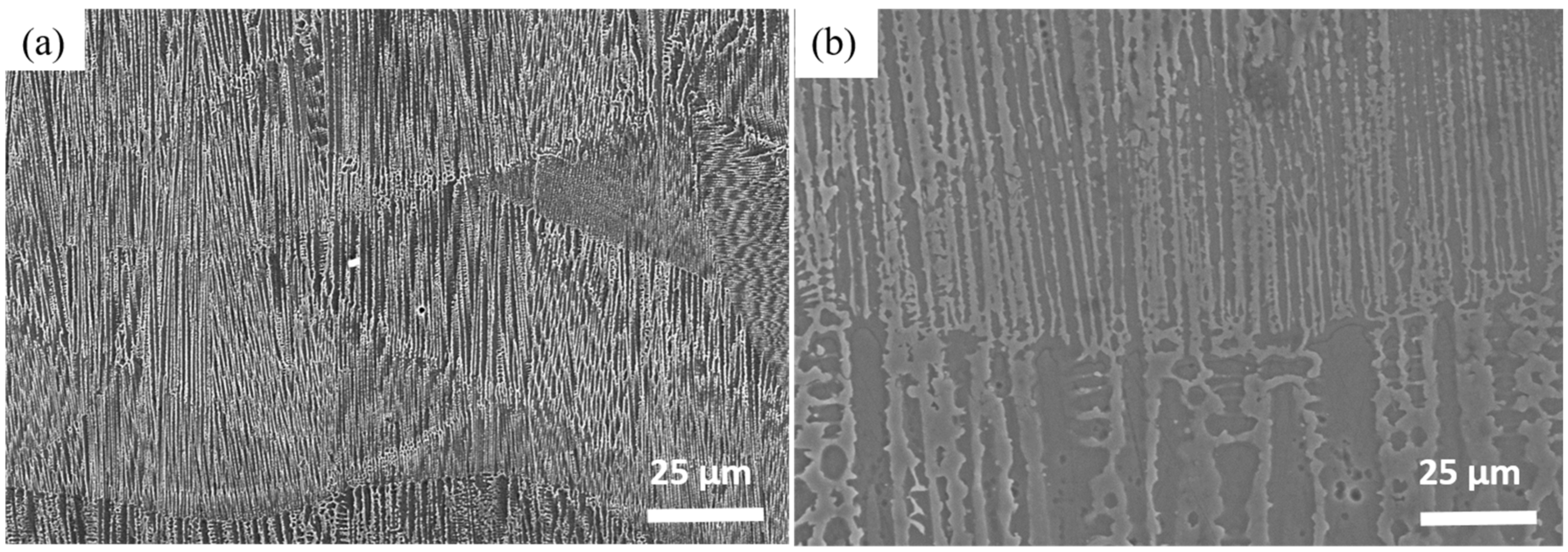
Figure 2 shows the SEM micrographs of the as-built specimen. It clearly shows the arch-shaped molten pool boundaries (MPB) resulting from the layer-by-layer processing (Figure 2a) [26,27]. At higher magnification, Figure 2b shows the dendritic and interdendritic structure, which demonstrates that the microstructure of the SLM material would be highly influenced by heat flux during layer-wise manufacturing, and consequently anisotropic microstructural features prevail.
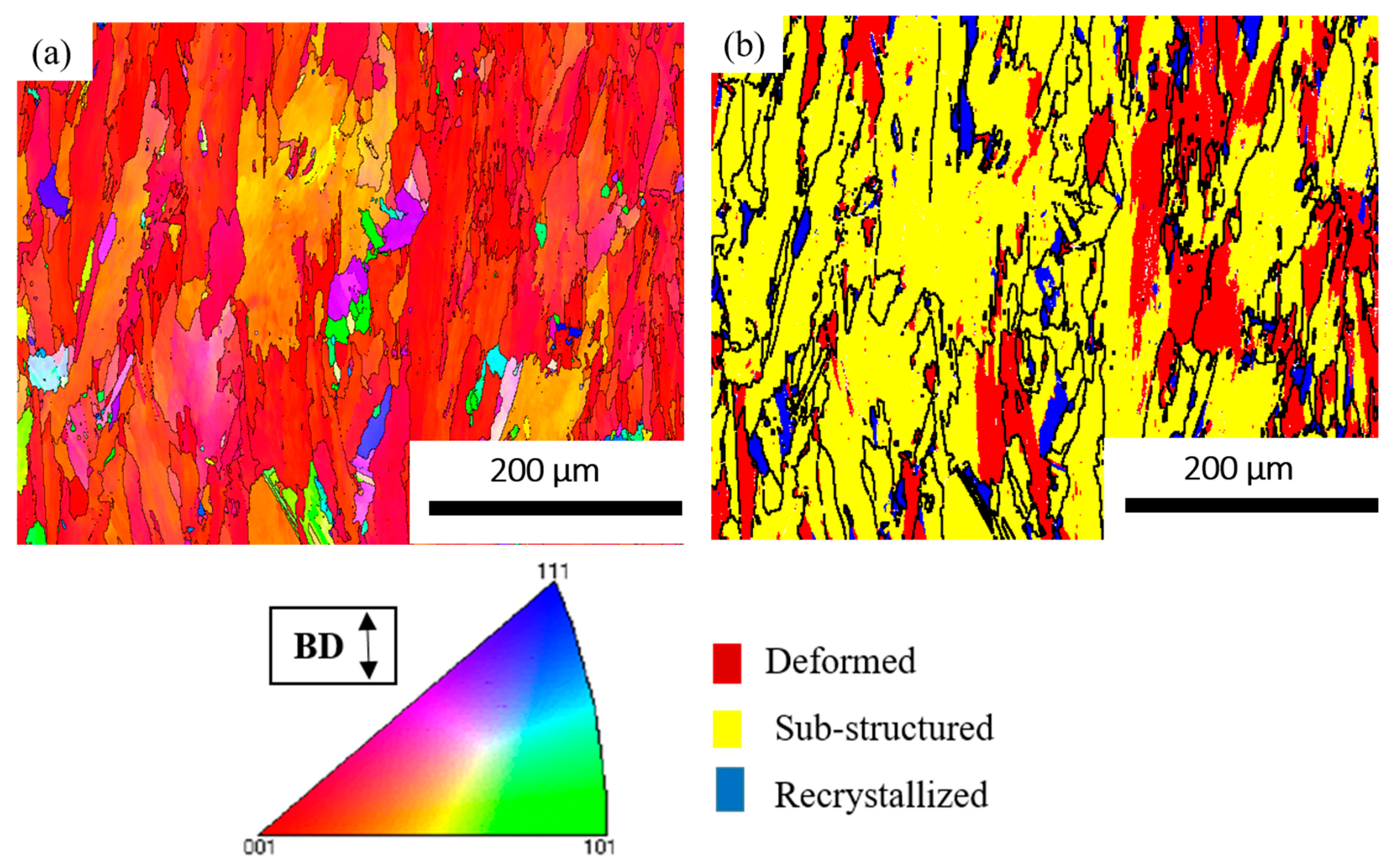
Inverse pole figure (IPF) micrographs of the as-built specimen showed columnar grains with a preferential alignment of <100> along the building direction (Figure 3a). This is because of epitaxial grain growth during the SLM process, and it leads to strong bonding between the layers [28]. The recrystallization map of the as-built specimen shows some of the grains are highly deformed, which signifies higher residual stored stresses (Figure 3b). Grain size and recrystallization fraction were calculated using Channel 5 software. It classifies grains into three types, i.e., deformed, substructured, and recrystallized. If the average angle in a grain exceeds the user-defined minimum angle (in this case 15°), it is considered a deformed grain. Some grains consist of subgrains whose internal misorientation is under 15°, but the misorientation from subgrain to subgrain is above 15°; these are called substructured. All the remaining grains were classified as recrystallized grains. In the as-built specimen, the average grain size and recrystallization fractions were 32 μm and 5.75%, respectively.
3.1.2. Heat-Treated Specimens
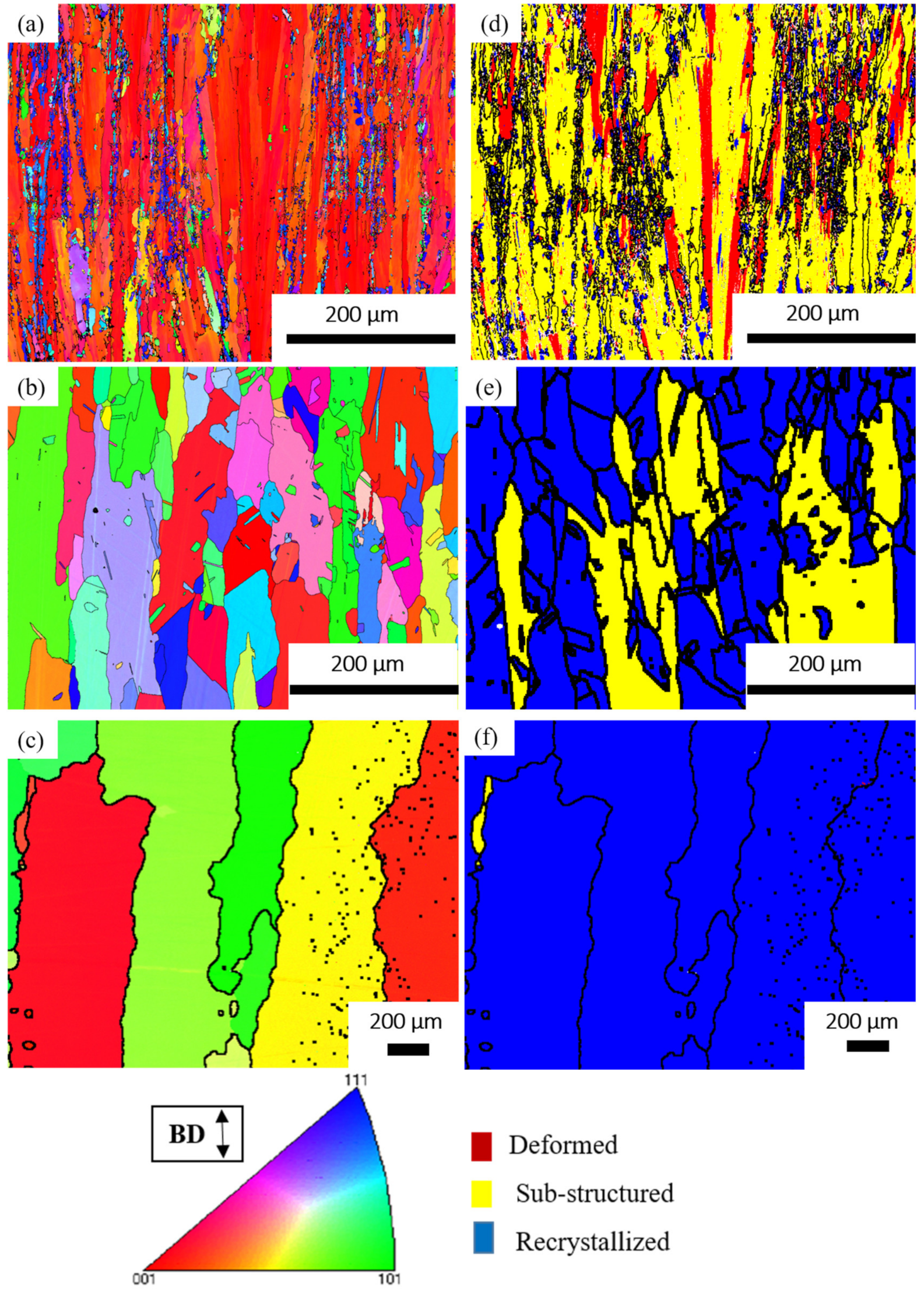
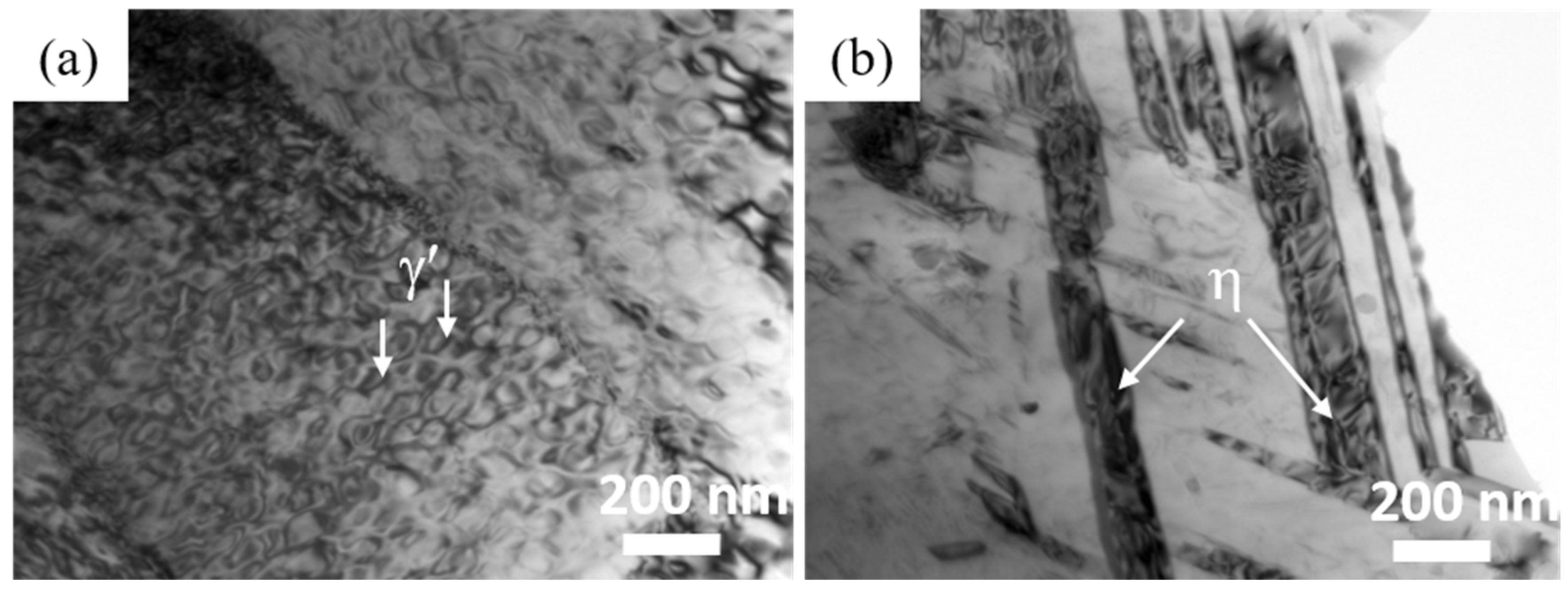
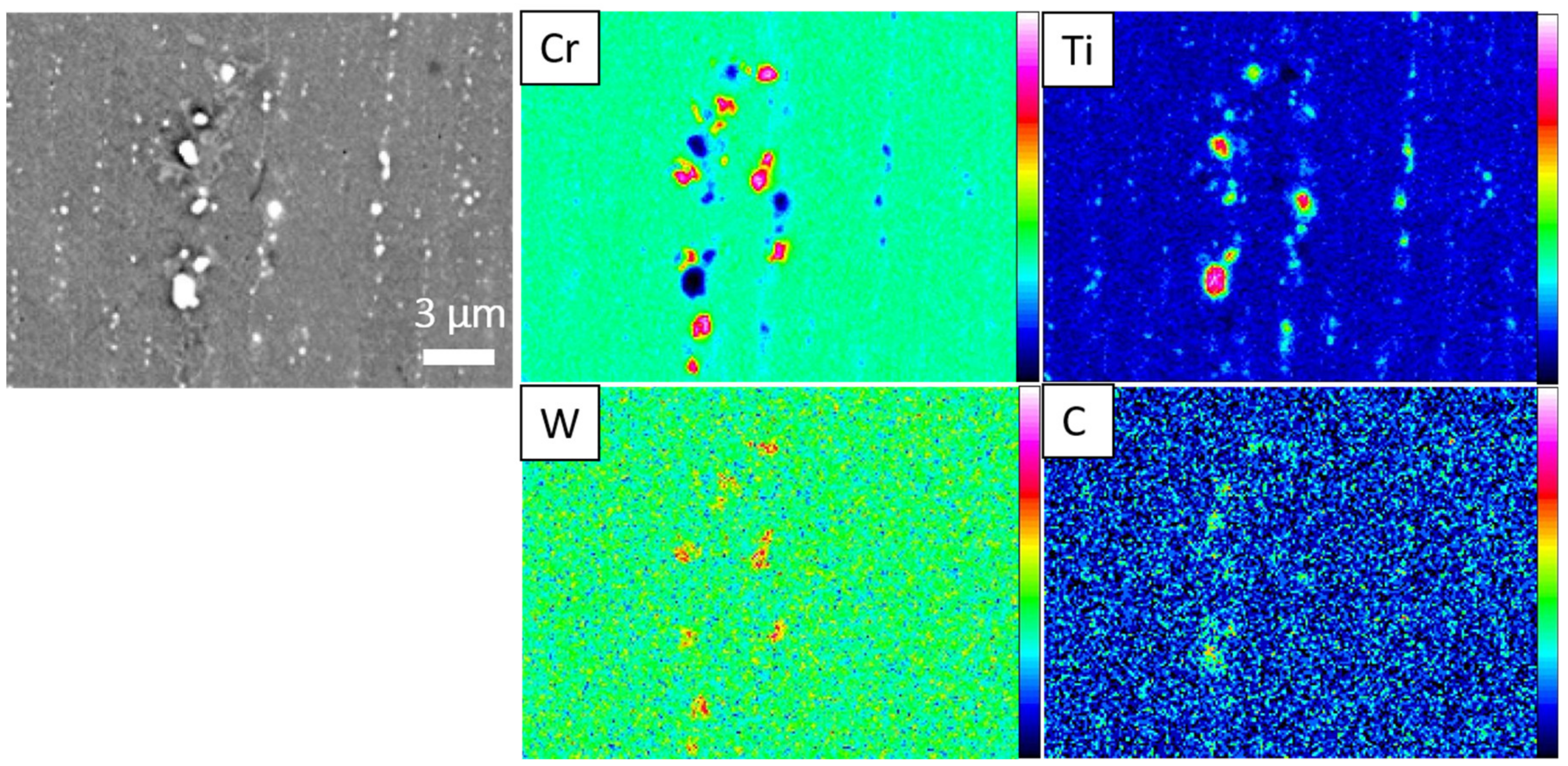
After the LTH treatment, the specimen showed a slight decrement of <100> orientation but the grain morphology did not change (Figure 5a). Furthermore, the small equiaxed grains formed between the columnar grains were found to be recrystallized grains by use of the recrystallization map (Figure 5d). In the LTH specimen, the average grain size and recrystallization fractions were 27 μm and 12.8%, respectively. Table 3 shows that there was no significant change in grain size before and after LTH treatment. The generation of residual stresses and dislocation density during the SLM process ultimately led to the nucleation of new recrystallized grains between columnar grains (Figure 5a). In the LTH specimen, TEM observation showed phase γ′ (44 nm size) and the rod-shaped (which are rich in Ni/Ti) η phase (Figure 6a,b). Electron Probe Micro Analysis (EPMA) analysis in the LTH specimen showed the dendritic structure; M23C6 carbides enriched in Cr, W, and C distributed along the columnar grain boundaries; and MC carbide enriched with Ti and C (Figure 7).
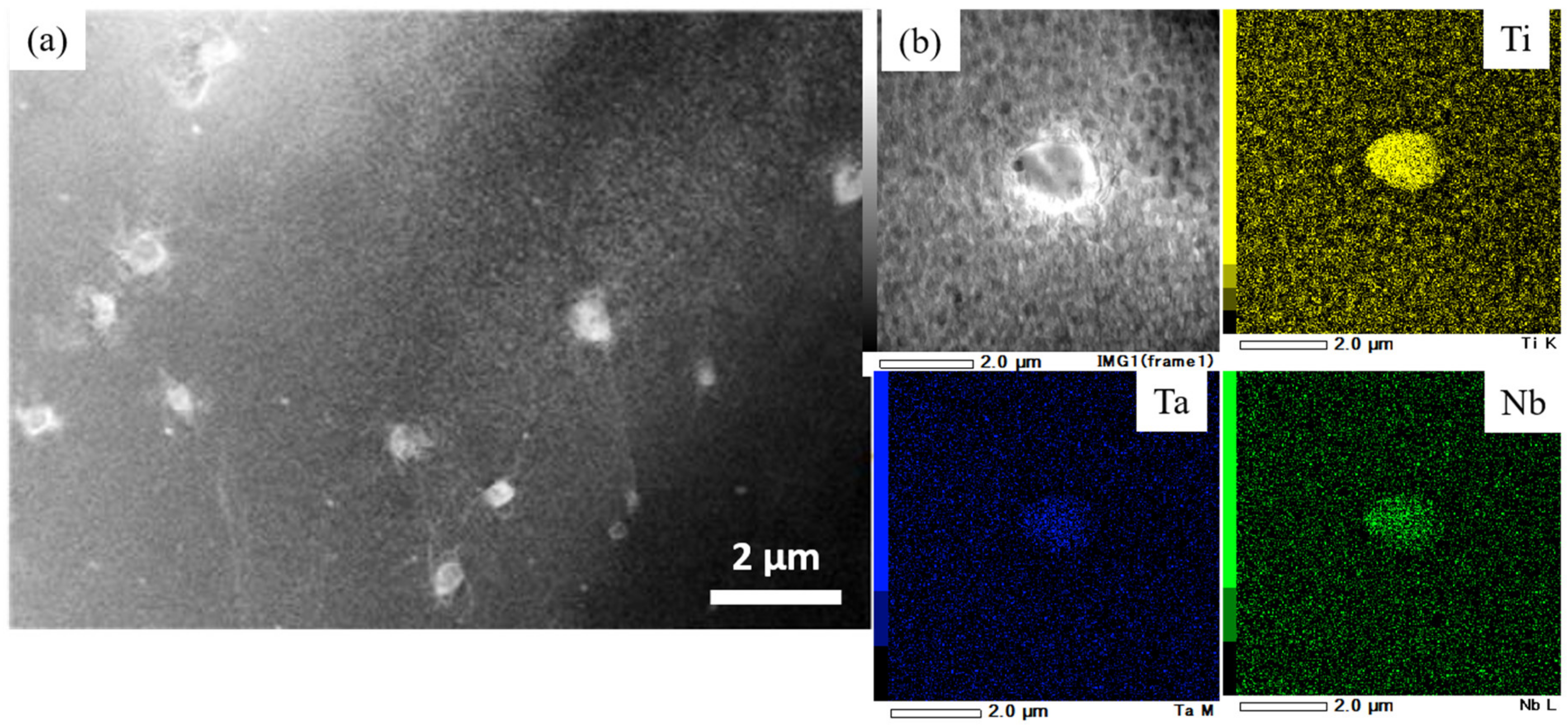
After HTH treatment, specimen texture became random (Figure 5b) and dislocation density decreased. As a result, the recrystallization fraction increased to 66% (Figure 5e) compared to the LTH specimen, which showed 12.8% recrystallization fraction. The grain size of the HTH specimen was about twice that of the LTH specimen because of grain growth. In Figure 5b, the IPF map of the HTH specimen showed columnar grains even after solution treatment at the higher temperature. TEM observation was carried out for the solution-treated specimen at 1240 °C/6 h. It revealed that the interdendritic regions completely disappeared, but MC carbides remained in round shapes with an average size of 100 nm (Figure 8a). It is known that MC carbides are stable up to 1300 °C. This suggests that carbide pinning has a significant effect on grain growth resistance in the lateral direction, which finally results in the formation of columnar crystals (Figure 5b).
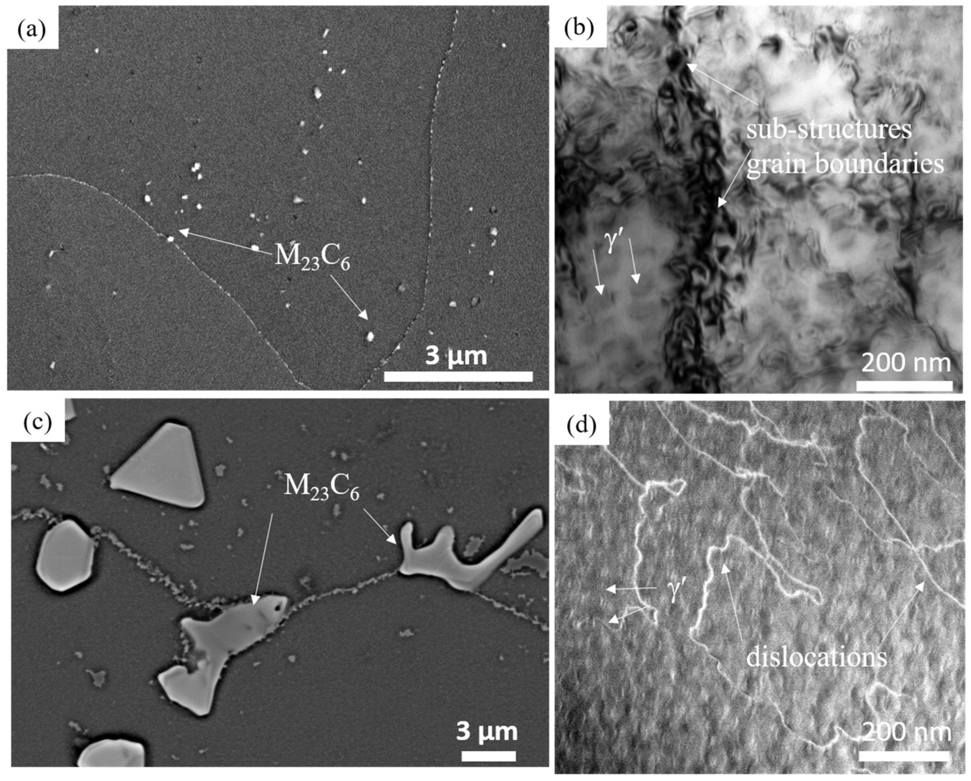
In the HTH specimen small M23C6 carbides were uniformly distributed at the grain boundaries but heterogeneously distributed within the grain (Figure 9a). Miskovic et al.’s study on a conventionally cast IN939 alloy showed that M23C6 carbides segregate at the grain boundaries discretely with a bigger size [29]. TEM observation showed γ′ precipitates in cuboid shape, as well as cell-like substructures inside the columnar grains (Figure 9b). The reason for the formation of cell-like substructures is unknown; similar observations were reported by Kanagaraja et al. [22]. The γ′-precipitate size was measured from TEM micrographs. The HTH specimen showed an average size of 53 nm, whereas the LTH specimens were approximately 44 nm in size.
For the cast-LTH specimen, EBSD observation was done at a higher magnification than for SLM specimen. It showed that grain size was on average 200 µm (Figure 5c) and recrystallization fraction was almost 100% (Figure 5f). The cast LTH specimen exhibited a grain size approximately 4 times larger than HTH specimen (Table 3). The cast LTH specimen showed carbides at grain boundaries, particularly M23C6 of various sizes from 1 to 10 µm. A curved shape grain boundary covered with fine carbides was observed (Figure 9c). TEM observation of the cast LTH specimen showed γ′ precipitates (41 nm) cuboid in shape and dislocations (Figure 9d). The γ′ precipitate sizes were the same between LTH and HTH specimens.
3.2. Creep Properties
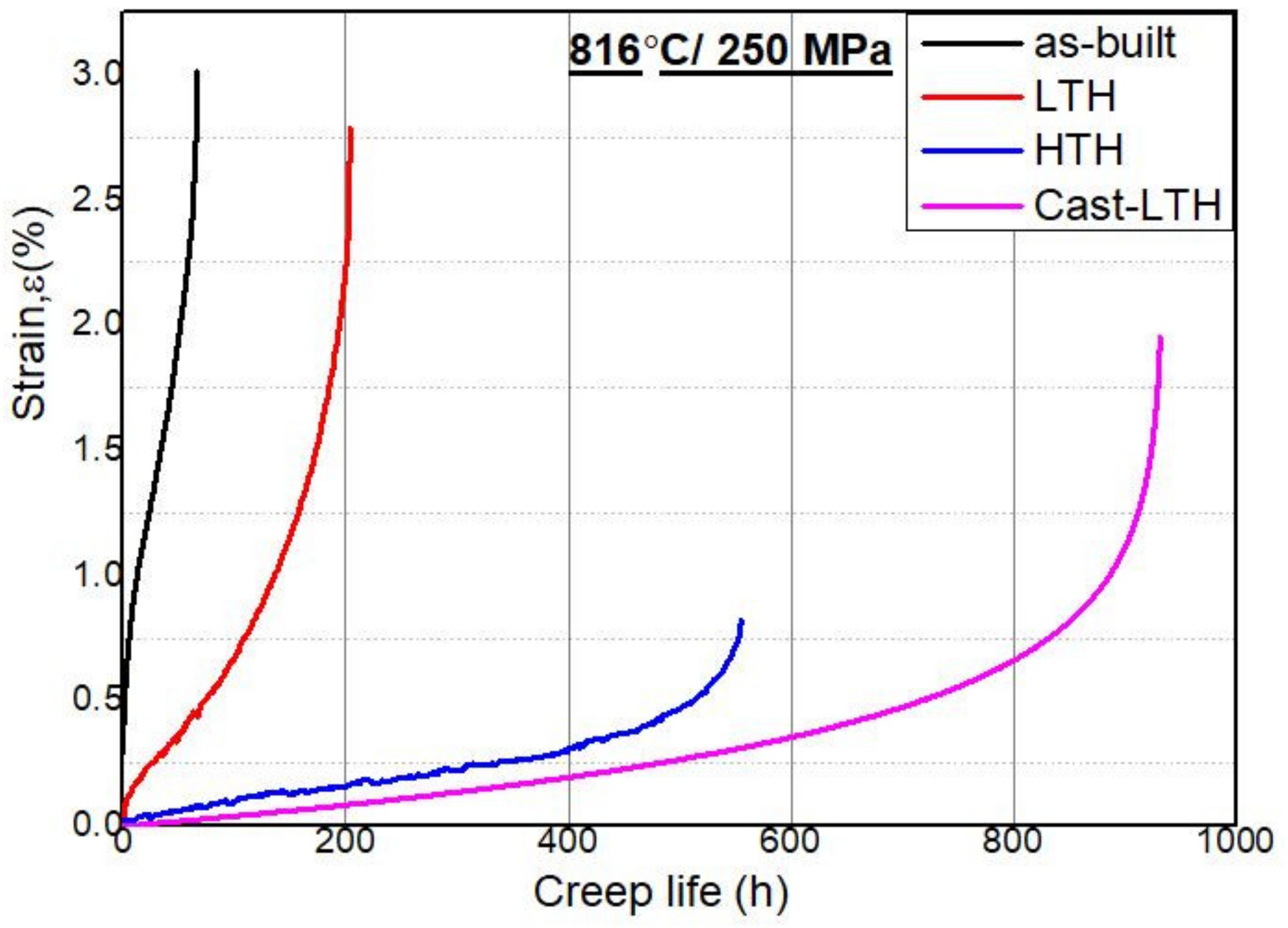
Figure 10 shows the creep curves at 816 °C/250 MPa. The as-built specimen showed a creep life of 66 h with a creep strain of 3%, whereas the LTH specimen showed 3 times longer creep life, 203 h, and elongation (2.7 %) that was almost the same (see Table 4). The HTH specimen showed good creep life of approximately 554 h, 2.7 times higher than that of the LTH specimen, but the elongation (0.8%) decreased drastically (see Table 4 and Figure 10). The cast LTH specimen exhibited superior creep life to the SLM specimen. It showed creep life (931 h) 1.6 times higher than the HTH specimen, but the elongation (1.9%) was poor compare to the LTH specimen (Table 4).
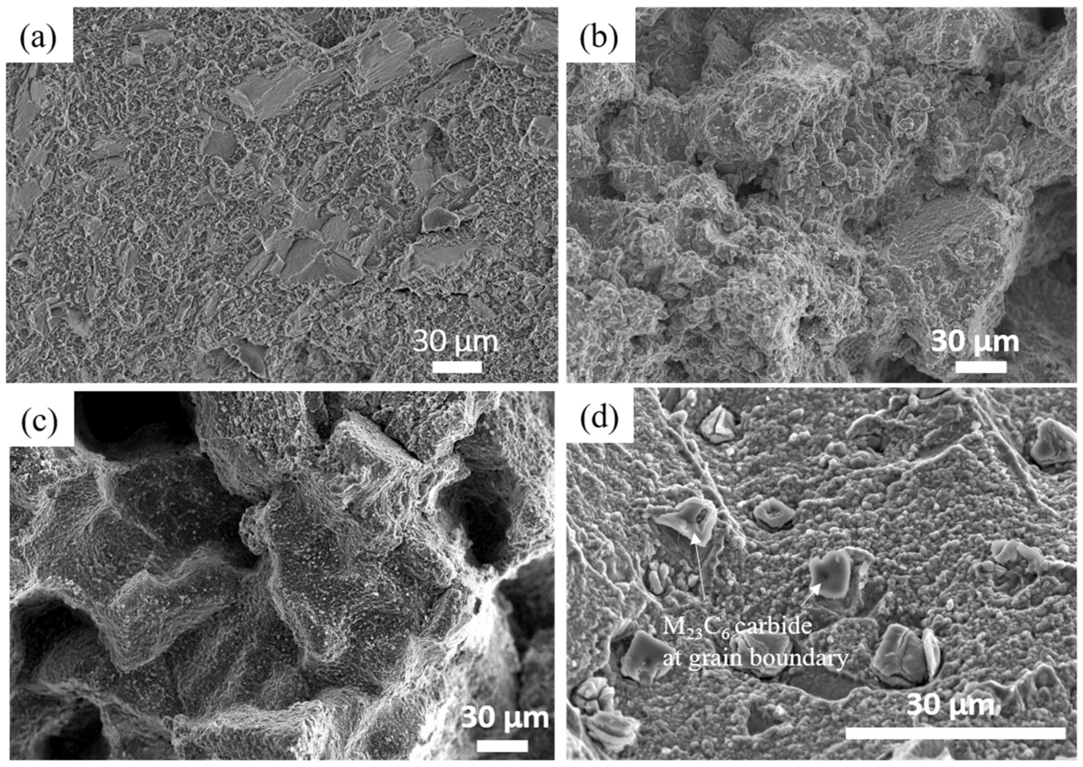
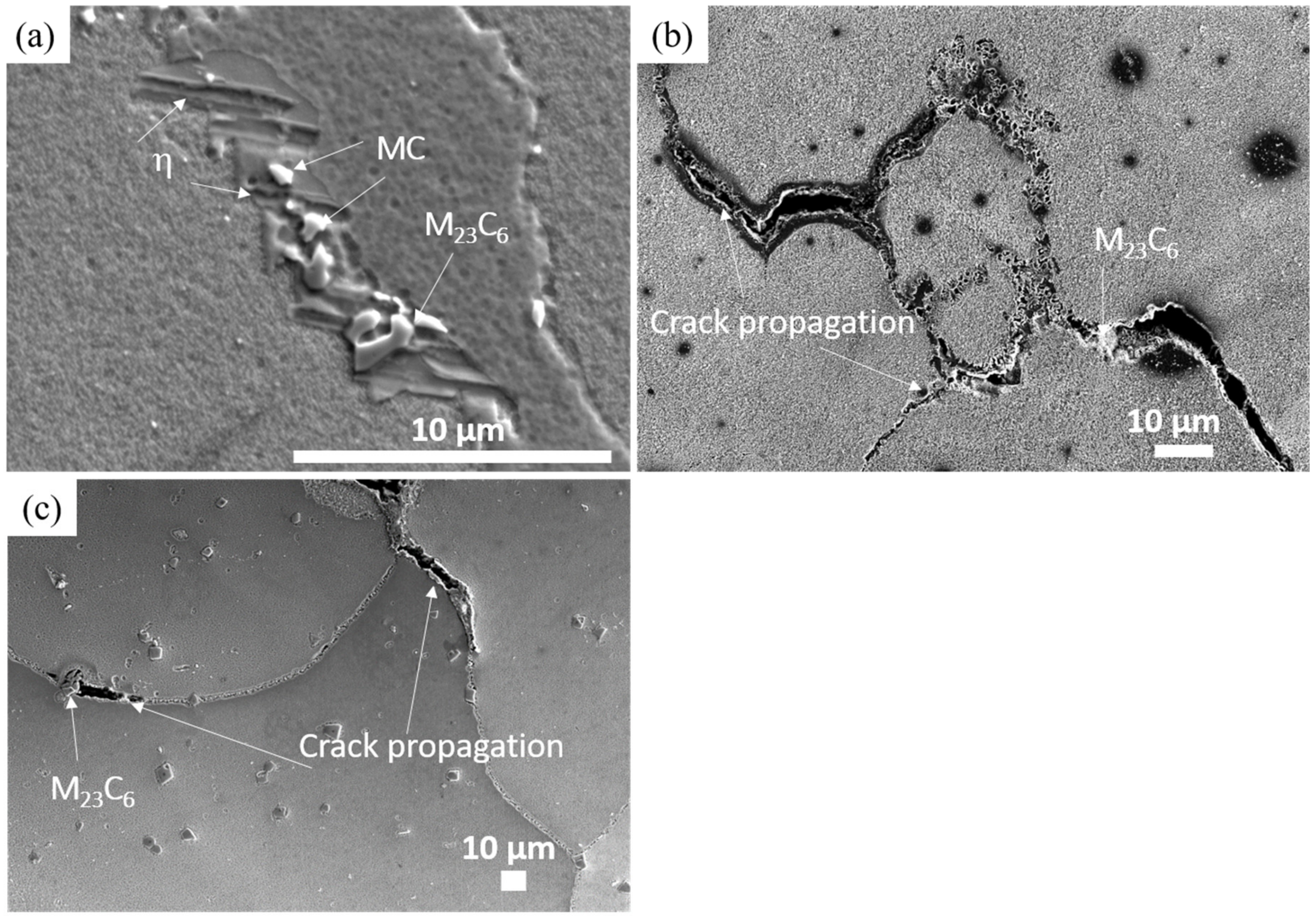
The fracture surface of the as-built, LTH, HTH, and cast LTH specimen is shown in Figure 11. In the as-built and LTH specimen, the entire fracture surface showed transgranular cleavage fracture. The HTH specimen showed a clear intergranular brittle fracture (Figure 11c), where cracks were present along the grain boundary. The cast-LTH fracture mode was comparable to the HTH specimen. It also exhibited a grain boundary brittle fracture (Figure 11d), and 1 µm M23C6 carbides along the grain boundaries (Figure 11d). Figure 12 shows the specimen-side microstructures near the creep-fractured surface. The LTH specimen showed carbides (MC and M23C6) and undesirable phase η at grain boundaries (Figure 12a). TCP phase η was aligned perpendicular to the stress axis. The HTH specimen showed small carbides and cracks propagating along the grain boundary (Figure 12b). Figure 12c shows crack nucleation and propagation through the grain boundaries in the cast LTH specimen. M23C6 carbides are acting as barriers against crack propagation at the grain boundary in the cast LTH specimen because the carbides were ~1–10 µm in size, and could thus easily stop crack propagation (Figure 12c).
4. Discussion
4.1. The Effects of Recrystallization on Creep Properties of SLM Specimen
Columnar grain formation in additive manufactured materials is a natural phenomenon. This has been proved by many researchers in different alloys [26,27]. The columnar grains are mainly attributed to epitaxial grain growth, a consequence of the layer-by-layer formation with rapid heating and cooling during the SLM process [2]. The as-built specimen showed columnar grain morphology in which grain boundaries are parallel to the loading axis (Figure 3). In general, the single crystal and columnar-grain alloy show better creep properties than the equiaxed-grain alloy. The <001> oriented columnar grain was observed in the as-built condition (Figure 3a). Therefore, good creep properties were expected of the specimen with <001>-columnar grain; however, the creep result was unexpected (Figure 10). The as-built specimen exhibited a very short creep life (66 h) compared to other specimens, although the creep strain was good (3%). This was mainly due to recrystallization during heat treatment, as a result of small grains formed at the columnar grain boundaries. The driving force for recrystallization comes from residual stress and high dislocation density, which occurred during the SLM process.
After the LTH heat treatment, the specimen maintained the columnar morphology (Figure 5a), but small recrystallized grains were formed between columnar grains (Figure 5d). A similar phenomenon was previously observed by several researchers who reported that both temperature and dislocation density were high enough to cause the recrystallization [30,31]. According to Messe et al., recrystallization will occur through conventional thermomechanical processing above recrystallization temperature, but will also take place in additive manufactured specimens when solution treatment is conducted above 1100 °C [27,32].
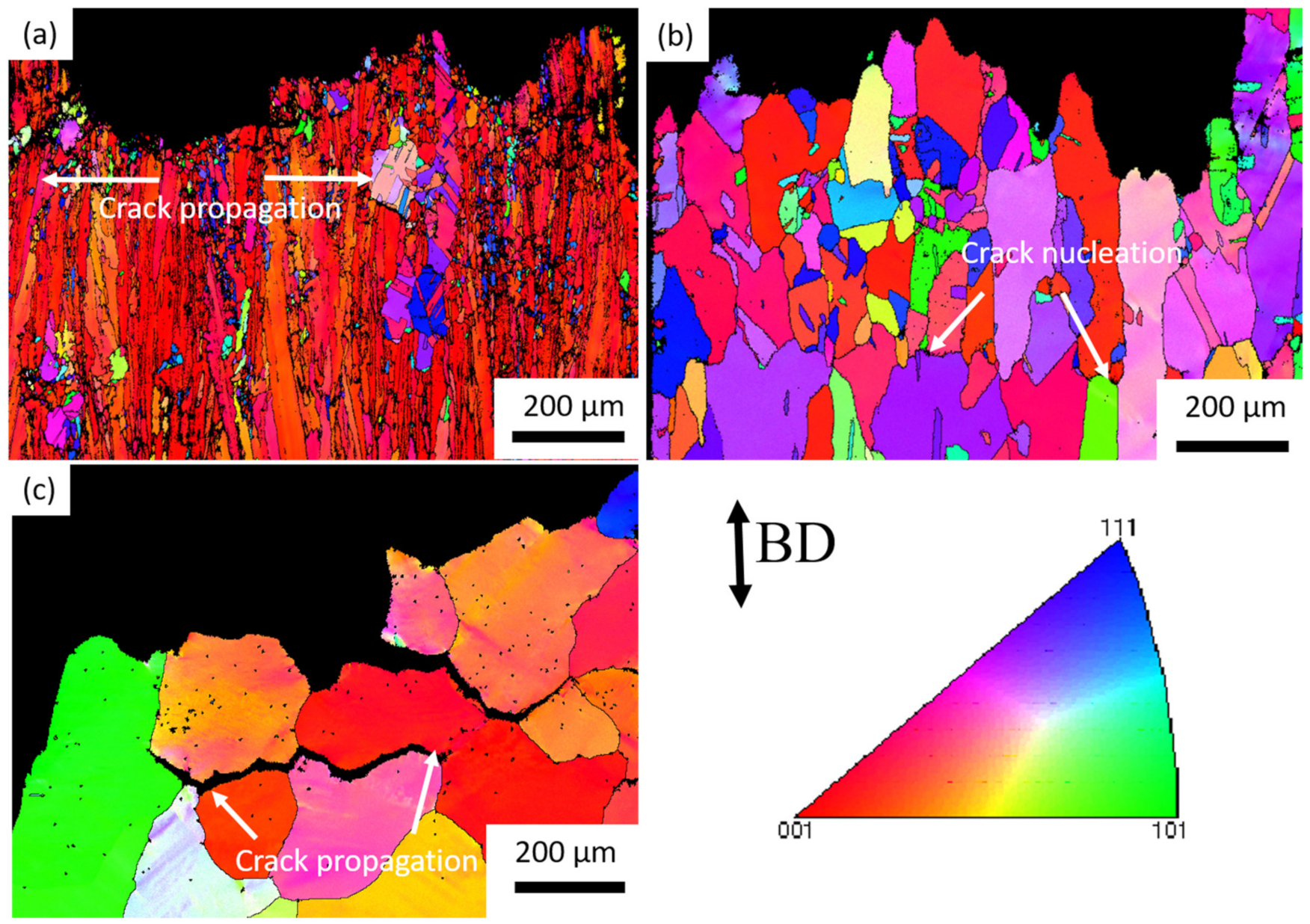
Creep life of the LTH specimen (203 h) was 3 times better than that of the as-built specimen, but creep strain (2.7%) was almost the same. In the LTH specimens, the recrystallized grains also decreased creep life (Figure 10). During the creep, the small grains at grain boundaries induced grain-boundary sliding and crack nucleation sites (Figure 13a). At high temperature, recrystallization allows the material to deform extensively so that deformation becomes localized in the neck, and failure eventually occurs. Crack propagation in the LTH specimen occurred along the direction transverse to the loading axis, which caused an intergranular ductile fracture (Figure 13a).
The HTH specimen demonstrated a creep life 2.7 times higher (554 h) than the LTH specimen, but creep strain (0.8%) was decreased drastically (Figure 10). The HTH specimen maintained columnar grains morphology (Figure 5b), and the average grain size was 50 μm after higher temperature solution treatment (1240 °C/6 h). Using high-temperature heat treatment, we obtained a fully recrystallized microstructure, and creep life was obviously improved by HTH treatment. The creep rate of the HTH-treated specimen was reduced and became roughly comparable with the cast specimen (Figure 10). The reason why the HTH specimen maintained a columnar structure was discovered in the TEM results (Figure 8). The small round MC carbides (where M is Ti, Nb, and Ta) prohibited grain growth in the lateral direction. Similar phenomena have been observed in carbon steel, and it has been shown that grain boundary movement is inhibited in carbides of 800 nm or less in size [33]. The grain morphology of the HTH specimen was similar to the directionally solidified (DS) Ni-base superalloys [34]. Grain boundaries normal to the stress axis are usually the crack initiation sites in the conventionally cast superalloy; therefore, the columnar grain morphology would improve the creep life. Crack nucleation and propagation in the HTH specimen through grain boundaries resulted in intergranular brittle fracture (Figure 13b).
The cast LTH specimen exhibited 1.6 times higher creep life compared to the SLM-HTH specimen (Figure 10; Table 4). It also displayed a grain size 4 times larger (200 µm, Figure 5c) than the HTH specimen, with lower dislocation density, which would mainly be responsible for the longer creep life. In Ni-based superalloys at high temperature, grain size controls creep properties [35]. Crack nucleation and propagation in the cast LTH specimen was similar to the HTH specimen, which caused intergranular brittle fracture (Figure 13c).
4.2. The Effect of Precipitates and Dislocation Density on Creep Properties
The γ′-precipitate (L12) is a main strengthening phase in IN939. γ′-precipitation has been confirmed in cast, wrought [17,33] and AM [22] IN939 alloys. The higher the volume fraction of the γ′ (Ni3 (Al, Ti)) precipitate in Ni-base superalloys, the better the strength because of the interaction of complex faults. The γ′-precipitate volume fraction increases with an increase in the amount of Al and Ti. Unfortunately, long exposures at temperatures above ~650 °C cause the γ′ precipitate to transform into TCP phase η with coarse platelets (HCP DO24) [36]. This transformation is closely associated with loss in strength, because it allows incoherency with the matrix phase-γ.
In the present study, the creep life of the LTH specimen (203 h) was 3 times higher than that of the as-built specimen because it possessed γ′ phase 44 nm in size (Figure 6a). Further, the creep life of the LTH specimen was shorter compared to the HTH and cast LTH specimens because it maintained the η-phase before and after the creep test (Figure 6b and Figure 12a). Figure 14a shows the TEM microstructure of the LTH specimen after the creep test. TEM results revealed a lot of dislocation entanglements around γ′-precipitates, which grew to an average of 71 nm in LTH specimen after the creep test (Figure 14a). Another reason for the shorter creep life in the LTH specimen would be the higher dislocation density (Figure 14a).
The elastic modulus is an anisotropic property that varies depending on the orientation of the grains that in turn significantly affects the creep-life of the Ni-based superalloys. In the stereographic triangle domain, <111>, <110>, and <100> orientations exhibit the highest, intermediate, and low elastic modulus, respectively. The higher modulus resembles higher creep resistance [37]. In the present study, the LTH specimen shows preferred orientation <100>, which results in low creep resistance due to its lower elastic modulus. However, when the texture changes from the preferred orientation of <100> (LTH specimen) to random (a mixture of <111>, <110>, and <100>) orientation (HTH specimen), the Young’s modulus increases and thus the HTH specimen revealed better creep resistance with loss in ductility. Incompatibilities of the slip systems at the grain boundary would be another reason for the poor ductility while also giving very good creep resistance.
In the HTH specimens, only γ′-precipitates and carbides were observed. The creep life of the HTH specimen was superior to the LTH specimen, mainly because it was covered with recrystallized grains and the resultant columnar grain morphology (Figure 5b). In addition, the elimination of the undesirable η-phase, decrease in dislocation density, and increment of γ′-precipitates size (53 nm) (Figure 9b) were effective. Moreover, creep life improvement in the HTH specimen may have been due to the γ’ precipitate (132 nm) growth during the creep test (Figure 14b). Nevertheless, the HTH specimen exhibited very poor creep elongation (brittle fracture) because of the lack of carbides at the grain boundaries, which results in a lack of coherency between the neighboring grains (Figure 13c). The cast LTH specimen showed the longest creep life because of the largest grain size (Figure 13c), low dislocation density (Figure 14c), and γ’ precipitate growth from 41 nm (Figure 9d) to 156 nm (Figure 14c) during the creep test. In addition, the steady-state creep rate is very low as compared to SLM processed specimens, which also helped in creep life improvement in the cast LTH specimen as compared to the SLM specimens.
The driving forces for precipitate coarsening during the creep test are significantly affected by the temperature and stresses, which are associated with the coherency strains at the γ/γ′ interface [37]. In addition, the presence of grain boundary carbides (M23C6) in discrete fashion at the grain boundaries helps resist boundary sliding and crack propagation (Figure 12c), which aids in creep life enhancement in the cast LTH specimen.
5. Conclusions
In this study, we examined the microstructures and creep properties of the as-built, LTH, and HTH conditions of SLM and referent conventional cast materials of an IN939 Ni-based superalloy. The following results were obtained.
- The as-built SLM material showed a columnar grain structure due to the epitaxial growth of dendrite structure. The dislocation density of the as-built condition was high. At the interdendritic region, Ti, Nb, Ta, and C elements were segregated during the solidification.
- In the LTH condition, small, recrystallized grains formed between the columnar grains; as a result, the rupture elongation was large and the creep life was poor. The formation of harmful phases like η also decreased the creep life.
- The creep life of the HTH specimen was 2.7 times longer than that of the LTH specimen due to attaining full recrystallization. In addition, γ′ precipitate size increment during the creep also improved creep life, but ductility was very poor compared to the LTH specimen.
- The cast-LTH specimen showed longer creep life than SLM specimens, mainly because of low creep strain rate, larger grain size, and γ′-phase coarsening during the creep test. In addition, the small size of M23C6 carbides remaining discretely at grain boundaries also improved creep life.
Author Contributions
Conceived and designed the experiments: K.K., S.B., Y.H., and C.-W.L. Performed the experiments: Y.H. and S.B. Wrote the paper: S.B. All authors have read and agreed to the published version of the manuscript.
Funding
This research was funded by the ALCA Program of the Japan Science and Technology Agency, JST (grant number JPMJAL1605), and the AMADA Foundation (AF-2018222-B3).
Conflicts of Interest
The authors declare no conflict of interest.
References
- Divya, V.D.; Munoz-Moreno, D.; Messe, O.M.D.M.; Barnard, J.S.; Baker, S.; Illston, T.; Stone, H.J. Microstructure of selective laser melted CM247LC nickel-based superalloy and its evolution through heat treatment. Mater. Charact. 2016, 114, 62–74. [Google Scholar] [CrossRef] [Green Version]
- Kuo, Y.L.; Kakehi, K. Influence of powder surface contamination in the Ni-based superalloy alloy718 fabricated by selective laser melting and hot isostatic pressing. Metals 2017, 7, 367. [Google Scholar] [CrossRef]
- Cherry, J.A.; Davies, H.M.; Mehmood, S.; Lavery, N.P.; Brown, S.G.R.; Sienz, J. Investigation into the effect of process parameters on microstructural and physical properties of 316L stainless steel parts by selective laser melting. Int. J. Adv. Manuf. Technol. 2014, 76, 869–879. [Google Scholar] [CrossRef] [Green Version]
- Islam, M.; Purtonen, T.; Piili, H.; Salminen, A.; Nyrhilä, O. Temperature profile and imaging analysis of laser additive manufacturing of stainless steel. Phys. Procedia 2013, 41, 835–842. [Google Scholar] [CrossRef] [Green Version]
- Järvinen, J.P.; Matilainen, V.; Li, X.; Piili, H.; Salminen, A.; Makela, I.; Nyrhila, O. Characterization of effect of support structures in laser additive manufacturing of stainless steel. Phys. Procedia 2014, 56, 72–81. [Google Scholar] [CrossRef] [Green Version]
- Piili, H.; Happonen, A.; Väistö, T.; Venkataramanan, V.; Partanen, J.; Salminen, A. Cost Estimation of Laser Additive Manufacturing of Stainless Steel. Phys. Procedia 2015, 78, 388–396. [Google Scholar] [CrossRef]
- Tang, H.P.; Qian, M.; Liu, N.; Zhang, X.Z.; Yang, G.Y.; Wang, J. Effect of Powder Reuse Times on Additive Manufacturing of Ti-6Al-4V by Selective Electron Beam Melting. JOM 2015, 67, 555–563. [Google Scholar] [CrossRef]
- Gong, X.; Anderson, T.; Chou, K. Review on powder-based electron beam additive manufacturing technology. In Proceedings of the ACME/ISCIE 2012 International Symposium on Flexible automation, St. Louis, MO, USA, 18–20 June 2012; pp. 507–515. [Google Scholar]
- Herzog, D.; Seyda, V.; Wycisk, E.; Emmelmann, C. Additive manufacturing of metals. Acta Mater. 2016, 117, 371–392. [Google Scholar] [CrossRef]
- Shiva, S.; Palani, I.A.; Mishra, S.K.; Paul, C.P.; Kukreja, L.M. Investigations on the influence of composition in the development of Ni-Ti shape memory alloy using laser based additive manufacturing. Opt. Laser Technol. 2015, 69, 44–51. [Google Scholar] [CrossRef]
- Loeber, L.; Biamino, S.; Ackelid, U.; Sabbadini, S.; Epicoco, P.; Pino, P.; Eckert, J. Comparison of selective laser and electron beam melted titanium. In Proceedings of the 22nd Annual International Solid Freeform Fabrication Symposium—An Additive Manufacturing Conerence (SFF 2011), Austin, TX, USA, 8–10 August 2011; pp. 547–556. [Google Scholar]
- Doubenskaia, M.; Domashenkov, A.; Smurov, I.; Petrovskiy, P. Study of Selective Laser Melting of intermetallic TiAl powder using integral analysis. Int. J. Mach. Tools Manuf. 2018, 129, 1–14. [Google Scholar] [CrossRef]
- Gussone, J.; Hagedorn, Y.C.; Gherekhloo, H.; Kasperovich, G.; Merzouk, T.; Hausmann, J. Microstructure of γ-titanium aluminide processed by selected laser melting at elevated temperatures. Intermetallics 2015, 66, 133–140. [Google Scholar] [CrossRef]
- Pinto, I.P.M.S. Additive Manufacturing of Nickel components using CMT process. Master’s Thesis, Instituto Superior Técnico, Lisbon, Portugal, May 2015. [Google Scholar]
- Murr, L.E.; Martinez, E.; Pan, X.M.; Gaytan, S.M.; Castro, J.R.; Terazzas, C.A.; Medina, F.; Wicker, R.B.; Abbott, D.H. Microstructures of Rene 142 nickel-based superalloy fabricated by electron beam melting. Acta Mater 2013, 61, 4289–4296. [Google Scholar] [CrossRef]
- Wang, F. Mechanical property study on rapid additive layer manufacture Hastelloy® X alloy by selective laser melting technology. Int. J. Adv. Manuf. Technol. 2012, 58, 545–551. [Google Scholar] [CrossRef]
- Wang, Z.; Guan, K.; Gao, M.; Li, X.; Chen, X.; Zeng, X. The microstructure and mechanical properties of deposited-IN718 by selective laser melting. J. Alloys Compd. 2012, 513, 518–523. [Google Scholar] [CrossRef]
- Warren, J.; Wei, D.Y. The cyclic fatigue behavior of direct age 718 at 149, 315, 454 and 538 °C. Mater. Sci. Eng. A 2006, 428, 106–115. [Google Scholar] [CrossRef]
- Jahangiri, M.R.; Arabi, H.; Boutorabi, S.M.A. Development of wrought precipitation strengthened IN939 superalloy. Mater. Sci. Technol. 2012, 28, 1470–1478. [Google Scholar] [CrossRef]
- Delargy, K.M.; Smith, G.D.W. phase composition and phase stability of a High-Chromium nickel-based superalloy, in939. Metall. Trans. A 1983, 14, 1771–1783. [Google Scholar] [CrossRef]
- Shaw, S.W.K. Response of in-939 To Process Variations. Metals 1980, 275–284. [Google Scholar]
- Kanagarajah, P.; Brenne, F.; Niendorf, T.; Maier, H.J. Inconel 939 processed by selective laser melting: Effect of microstructure and temperature on the mechanical properties under static and cyclic loading. Mater. Sci. Eng. A 2013, 588, 188–195. [Google Scholar] [CrossRef]
- Quested, P.N.; Osgerby, S. Mechanical properties of conventionally cast, directionally solidified, and single-crystal superalloys. Mater. Sci. Technol. 2013, 836. [Google Scholar] [CrossRef]
- Papadaki, C.; Li, W.; Ying, S.; Salvati, E.; Zhang, H.; Romano Brandt, L.; Sui, T.; Korsunsky, A.M. Microstructural Variations During Interrupted Creep Tests on P/M Polycrystalline Nickel-Base Superalloy. In Proceedings of the 14th International Conference on Fracture 2017 (ICF-14), Cassino, Italy, 18–23 June 2017. [Google Scholar]
- Philpott, W.; Jepson, M.A.E.; Thomson, R.C. Comparison of the effects of a conventional heat treatment between cast and selective laser melted IN939 alloy. In Advanced Materials Technology for Fossil Power Plants, Proceedings of the Eight International Conference (EPRI 2016), Albuferia, Portugal, 11–14 October 2016; ASM International: Novelty, OH, USA, 2016; pp. 735–746. [Google Scholar]
- Popovich, V.A.; Borisov, E.V.; Popovich, A.A.; Sufiiarov, V.S.; Masaylo, D.V.; Alzina, L. Functionally graded Inconel 718 processed by additive manufacturing: Crystallographic texture, anisotropy of microstructure and mechanical properties. Mater. Des. 2017, 114, 441–449. [Google Scholar] [CrossRef]
- Messé, O.M.D.M.; Muñoz-Moreno, R.; Illston, T.; Baker, S.; Stone, H.J. Metastable carbides and their impact on recrystallisation in IN738LC processed by selective laser melting. Addit. Manuf. 2017, 22, 394–404. [Google Scholar] [CrossRef]
- Tan, C.; Zhou, K.; Ma, W.; Zhang, P.; Liu, M.; Kuang, T. Microstructural evolution, nanoprecipitation behavior and mechanical properties of selective laser melted high-performance grade 300 maraging steel. Mater. Des. 2017, 134, 23–34. [Google Scholar] [CrossRef]
- Mišković, Z.; Jovanović, M.; Gligić, M.; Lukić, B. Microstructural investigation of IN 939 superalloy. Vacuum 1992, 43, 709–711. [Google Scholar] [CrossRef]
- Liu, F.; Lin, X.; Yang, G.; Song, M.; Chen, J.; Huang, W. Microstructure and residual stress of laser rapid formed Inconel 718 nickel-base superalloy. Opt. Laser Technol. 2011, 43, 208–213. [Google Scholar] [CrossRef]
- Liu, F.; Lin, X.; Huang, C.; Song, M.; Yang, G.; Cheng, J.; Huang, W. The effect of laser scanning path on microstructures and mechanical properties of laser solid formed nickel-base superalloy Inconel 718. J. Alloys Compd. 2011, 509, 4505–4509. [Google Scholar] [CrossRef]
- Hu, Y.L.; Lin, X.; Lin, Y.L.; Wang, Y.L.; Zhang, S.Y.; Lu, X.F.; Huang, W.D. Effect of heat treatment on the microstructural evolution and mechanical properties of GH4099 additive-manufactured by directed energy deposition. J. Alloys Compd. 2019, 800, 163–173. [Google Scholar] [CrossRef]
- Hutchinson, C.R.; Zurob, H.S.; Sinclair, C.W.; Brechet, Y.J.M. The comparative effectiveness of Nb solute and NbC precipitates at impeding grain-boundary motion in Nb steels. Scr. Mater. 2008, 59, 635–637. [Google Scholar] [CrossRef]
- Guo, J.T.; Yuan, C.; Yang, H.C.; Lupinc, V.; Maldini, M. Creep-rupture behavior of a directionally solidified nickel-base superalloy. Metall. Mater. Trans. A 2001, 32, 1103–1110. [Google Scholar] [CrossRef]
- Thébaud, L.; Villechaise, P.; Crozet, C.; Devaux, A.; Bechet, D.; Franchet, J.-M.; Rouffie, A.-L.; Mills, M.; Cormier, J. Is there an optimal grain size for creep resistance in Ni-based disk superalloys? Mat. Sci. Eng. 2017, 716, 274–283. [Google Scholar] [CrossRef]
- Long, F.; Yoo, Y.S.; Yo, C.Y.; Seo, S.M.; Song, Y.S.; Yin, T.; Hu, Z.Q. Formation of η and σ phase in three polycrystalline superalloys and their impact on tensile properties. Mater. Sci. Eng. A 2009, 527, 361–369. [Google Scholar] [CrossRef]
- Pollock, T.M.; Tin, S. Nickel-Based Superalloys for Advanced Turbine Engines: Chemistry, Microstructure and Properties. J. Propuls. Power 2006, 22, 361–374. [Google Scholar] [CrossRef]
Figure 1.
Creep specimen orientation and dimensions (in mm).

Figure 2.
Scanning electron microscope (SEM) micrographs of the as-built condition at (a) lower and (b) higher magnifications.
Figure 2.
Scanning electron microscope (SEM) micrographs of the as-built condition at (a) lower and (b) higher magnifications.

Figure 3.
Orientation and characteristics of electron backscatter diffraction (EBSD) inverse pole figure (IPF) maps of as-built selective laser melting (SLM) specimens. (a) IPF map and (b) recrystallization fraction maps along building direction. The EBSD observation was done along the building direction, and the IPF color code is also shown.

Figure 4.
Scanning transmission electron microscopy (STEM) micrograph and elemental maps of the as-built specimen.
Figure 4.
Scanning transmission electron microscopy (STEM) micrograph and elemental maps of the as-built specimen.

Figure 5.
Orientation and characteristics of EBSD IPF maps of (a) lower temperature heat treatment (LTH); (b) higher temperature heat treatment (HTH); and (c) cast-LTH. specimens. Recrystallization fraction maps of (d) LTH, (e) HTH, and (f) cast LTH specimens. The EBSD observation was done along the building direction, and the IPF color code is shown.

Figure 6.
STEM micrographs of the LTH specimen showing (a) γ′ precipitates and (b) η phase.

Figure 7.
Electron Probe Micro Analyzer (EPMA) micrographs of 2 types of carbides (M23C6 and MC) in the LTH specimen.
Figure 7.
Electron Probe Micro Analyzer (EPMA) micrographs of 2 types of carbides (M23C6 and MC) in the LTH specimen.

Figure 8.
(a) STEM micrographs of the solution-treated (1240 °C/6 h/FC) specimen in which the interdendritic layer completely disappeared, and (b) Energy Dispersive X-Ray Spectroscopy (EDS) mapping of MC carbides, where M is Ti, Nb, and Ta.
Figure 8.
(a) STEM micrographs of the solution-treated (1240 °C/6 h/FC) specimen in which the interdendritic layer completely disappeared, and (b) Energy Dispersive X-Ray Spectroscopy (EDS) mapping of MC carbides, where M is Ti, Nb, and Ta.

Figure 9.
(a) M23C6 at the grain boundary. (b) γ′ Precipitates, cuboid in shape, and cell-like substructures in the HTH specimen. (c) M23C6 at the grain boundary. (d) Dislocations and γ′ precipitates in the cast LTH specimen.
Figure 9.
(a) M23C6 at the grain boundary. (b) γ′ Precipitates, cuboid in shape, and cell-like substructures in the HTH specimen. (c) M23C6 at the grain boundary. (d) Dislocations and γ′ precipitates in the cast LTH specimen.

Figure 10.
Creep curves of SLM specimens at 816 °C under 250 MPa.

Figure 11.
Fracture surfaces of creep-ruptured (a) as-built, (b) LTH, (c) HTH, and (d) cast LTH specimens crept at 816 °C/250 MPa.
Figure 11.
Fracture surfaces of creep-ruptured (a) as-built, (b) LTH, (c) HTH, and (d) cast LTH specimens crept at 816 °C/250 MPa.

Figure 12.
Precipitates and crack propagation in the creep-ruptured (a) LTH, (b) HTH, and (c) cast LTH specimens crept at 816 °C/250 MPa.
Figure 12.
Precipitates and crack propagation in the creep-ruptured (a) LTH, (b) HTH, and (c) cast LTH specimens crept at 816 °C/250 MPa.

Figure 13.
Orientation and characteristics of EBSD IPF maps of creep fractured (a) LTH, (b) HTH, and (c) cast LTH specimens.
Figure 13.
Orientation and characteristics of EBSD IPF maps of creep fractured (a) LTH, (b) HTH, and (c) cast LTH specimens.

Figure 14.
STEM micrographs show γ’ precipitate growth after creep test at 816 °C/250 MPa: (a) LTH, (b) HTH, and (c) cast LTH specimens.
Figure 14.
STEM micrographs show γ’ precipitate growth after creep test at 816 °C/250 MPa: (a) LTH, (b) HTH, and (c) cast LTH specimens.


Table 1.
Nominal composition of the gas-atomized IN939 powder (in wt.%).
| Elements | Cr | Co | Ti | Al | W | Ta | Nb | C | Fe | S | Mg | Ni |
|---|---|---|---|---|---|---|---|---|---|---|---|---|
| powder | 22.5 | 19 | 3.7 | 1.9 | 2.0 | 1.4 | 1.0 | 0.15 | - | - | - | Bal |
| cast | 22.5 | 19.0 | 3.6 | 1.9 | 2.0 | 1.4 | 1.0 | 0.2 | 0.1 | 0.0002 | 0.0012 | Bal. |
Table 2.
Heat treatment conditions and samples codes.
| Specimen | Heat Treatment | Condition | Abbreviation |
|---|---|---|---|
| SLM | 1160 °C/4 h/FC+ 850 °C/16 h/AC | lower temperature heat treatment | LTH |
| SLM | 1240 °C/6 h/FC+ 850 °C/16 h/AC | higher temperature heat treatment | HTH |
| Cast | 1160 °C/4 h/FC+ 850 °C/16 h/AC | lower temperature heat treatment | Cast-LTH |
Table 3.
Grain size and recrystallization fraction in the specimens.
| Specimen Condition | Average Grain Size (µm) | Recrystallization Fraction (%) |
|---|---|---|
| LTH | 27 | 12.8 |
| HTH | 50 | 66 |
| Cast-LTH | 200 | 99.9 |
Table 4.
Creep lives and creep strain.
| Specimen | Creep Life (h) | Strain (%) |
|---|---|---|
| As-built | 66 | 3 |
| LTH | 203 | 2.7 |
| HTH | 554 | 0.8 |
| Cast-LTH | 931 | 1.9 |
© 2020 by the authors. Licensee MDPI, Basel, Switzerland. This article is an open access article distributed under the terms and conditions of the Creative Commons Attribution (CC BY) license (http://creativecommons.org/licenses/by/4.0/).
Share and Cite
MDPI and ACS Style
Banoth, S.; Li, C.-W.; Hiratsuka, Y.; Kakehi, K. The Effect of Recrystallization on Creep Properties of Alloy IN939 Fabricated by Selective Laser Melting Process. Metals 2020, 10, 1016. https://doi.org/10.3390/met10081016
AMA Style
Banoth S, Li C-W, Hiratsuka Y, Kakehi K. The Effect of Recrystallization on Creep Properties of Alloy IN939 Fabricated by Selective Laser Melting Process. Metals. 2020; 10(8):1016. https://doi.org/10.3390/met10081016
Chicago/Turabian StyleBanoth, Santhosh, Chen-Wei Li, Yo Hiratsuka, and Koji Kakehi. 2020. "The Effect of Recrystallization on Creep Properties of Alloy IN939 Fabricated by Selective Laser Melting Process" Metals 10, no. 8: 1016. https://doi.org/10.3390/met10081016
Note that from the first issue of 2016, this journal uses article numbers instead of page numbers. See further details here.