Effect of Mo Addition on The Microstructure and Mechanical Properties of CoCuFeNi High Entropy Alloy


1
Department of Materials Science and Engineering, Dalian Maritime University, Dalian 116026, China
2
Department of Materials Science and Engineering, City University of Hong Kong, Hong Kong 999077, China
*
Author to whom correspondence should be addressed.
Metals 2020, 10(8), 1017; https://doi.org/10.3390/met10081017
Submission received: 1 July 2020
/
Revised: 16 July 2020
/
Accepted: 26 July 2020
/
Published: 28 July 2020
Abstract
:In order to reveal the effect of Mo addition on the microstructure and mechanical properties, (CoCuFeNi)100-xMox (x = 0, 10, 15, 19, and 25, x values in atomic ratio) high entropy alloys were prepared by vacuum arc-melting. The results showed that with Mo addition, the μ phase formed and serious separation occurred in the high entropy alloys. The content of μ phase increased with the increase in Mo content. The microstructure of the alloys changed from an initial single-phase face-center-cubic (FCC) solid solution structure (x = 0) to a hypoeutectic microstructure (x = 15), then to a full eutectic microstructure (x = 19), and finally to a hypereutectic microstructure (x = 25). Coherent interface between μ phase and FCC phase was observed. The (CoCuFeNi)81Mo19 alloy with fully eutectic microstructures exhibited the highest yield strength of 557 MPa and fracture strength of 767 MPa in tensile tests at room temperature. The fracture surface revealed that the formation of great amounts of the μ phase resulted in the loss of ductility of (CoCuFeNi)100-xMox alloys.
1. Introduction
High entropy alloys (HEAs), usually containing five or more principle elements, have attracted a lot of attention recently due to their unique properties such as good ductility [1], high toughness, excellent cryogenic and high temperature mechanical properties [2,3], good corrosion resistance and wear resistance [4,5] etc. and have the potential to be used in critical application. Until now, a great deal of research has indicated that a single phase structure such as face center cubic (FCC) [6], body center cubic (BCC) [7], and hexagonal close-packed (HCP) [8] could be formed in different HEAs. HEAs with a single FCC phase such as CoCuFeNiMn HEAs have gained more attention than others due to their excellent mechanical properties at room and cryogenic temperature [2]. However, although it exhibits excellent ductility at room temperature, its low yield strength (about 300 MPa) restricts its wide application [9].
Several methods have been used to strengthen HEAs with a single phase [10,11,12] such as grain refinement, second phase strengthening, strain strengthening, etc. Among them, element addition is one common method to enhance the mechanical properties of alloys. Alloy elements such as Hf [13], Nb [14], V [15], Zr [16], etc. could result in the formation of a second phase and lattice distortion, both of which could impede dislocation movement in HEAs.
Recently, a CoCuFeNi HEA containing equal amounts of Fe, Co, Ni, and Cu with a single FCC phase was investigated [17,18,19,20]. It has potential to be used in semiconductor devices and spacecraft engines due to its excellent magnetic, elastic, thermodynamic properties, and good corrosion resistance [17]. However, its yield strength is only about 300 MPa. The addition of TiC particles, Nb and Sn elements have been used to improve its mechanical properties. It has been reported that CoCuFeNi/(TiC + C) composites exhibited simultaneously improved ductility and strength [17]. The FeCoCuNiSn0.05 alloy exhibited a tensile strength of 633 MPa with an elongation of 19.8% [20]. The Nb addition could also increase the yield strength of CoCuFeNi HEAs due to solution strengthening and second phase strengthening [19].
As is widely known, the molybdenum (Mo) element has a relative lager atomic radio and high modulus (325 GPa) [21,22], which could result in larger lattice distortion. Meanwhile, it has been reported that σ and μ phases could be formed in the CoCrFeNiMo0.3 HEA with Mo addition, resulting in a high yield strength of 1.2 GPa in a tensile test [23]. Therefore, the alloying effect of Mo on the microstructure and mechanical properties of CoCuFeNi HEAs was investigated in this study.
2. Experiments
(CoCuFeNi)100-xMox (x = 0, 10, 15, 19, and 25, x values in atomic ratio) HEAs were produced by arc melting of the pure elements in argon atmosphere. The ingots were remelted at least five times to ensure chemical homogeneity. The phase constitution was analyzed with a X-ray diffractometer (XRD, Rigaku, Japan) using Cu Kα radiation scanning at a rate of 4°/min. The microstructure was examined with scanning electron microscopy (SEM, XL30, FEI, Hillsboro, OR, USA) and transmission electron microscopy (TEM, 2100F, JEOL Ltd., Tokyo, Japan). The compositions of the alloys were obtained by energy dispersive x-ray spectrometers (EDS, X-Max 50 mm2, Oxford instrument, Oxford, UK) equipped on the SEM. Specimens of size 2 × 1 × 50 mm3 were cut by wire cutting for tensile tests, which were carried out at a speed of 0.5 mm/min. Fracture surfaces after tensile tests were observed by SEM. Vickers hardness was measured at a load of 1 kg for 15 s.
3. Results and Discussions
3.1. Phase Structure
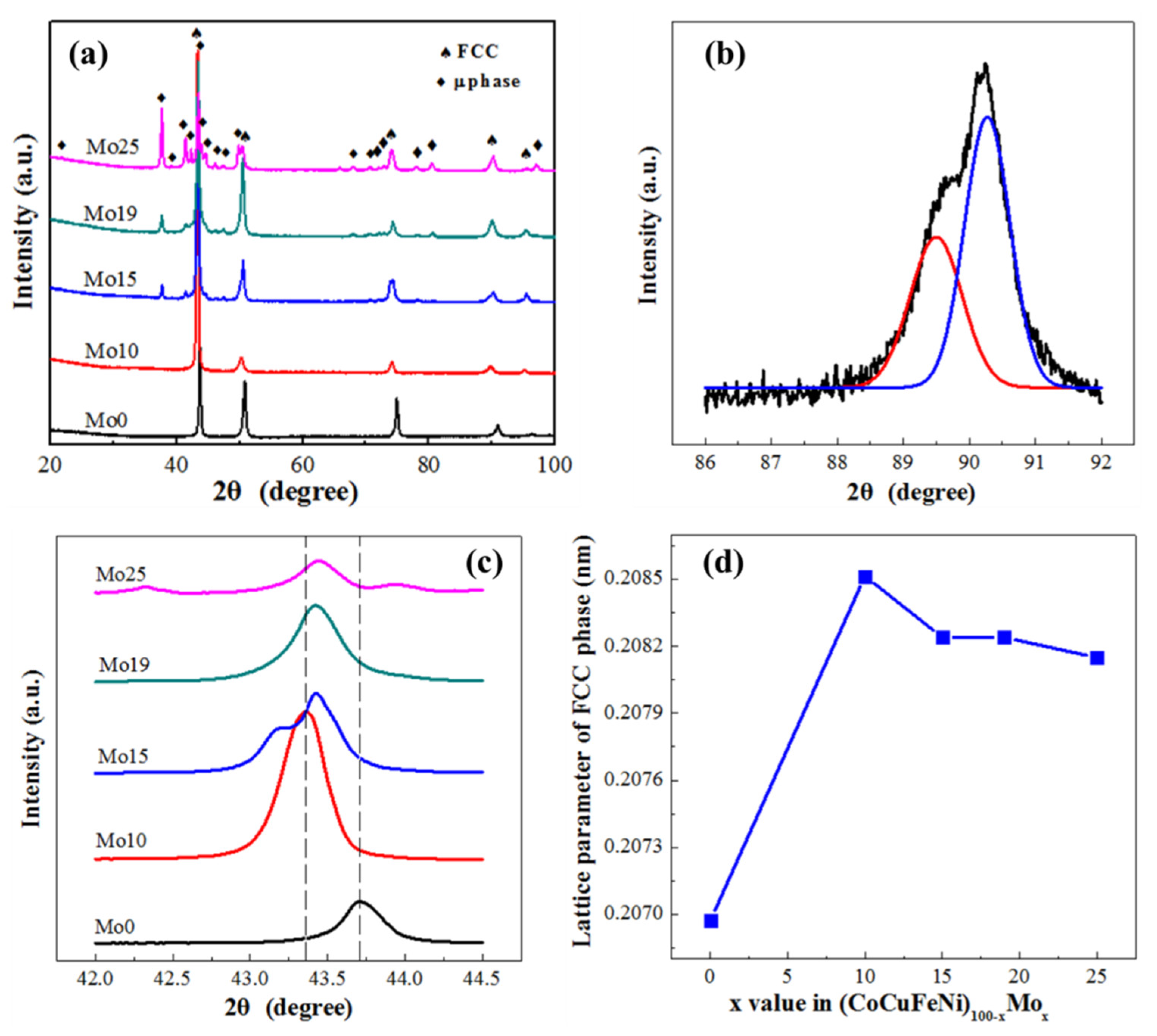
The phase structures in as-cast (CoCuFeNi)100-xMox HEAs (x = 0, 10, 15, 19 and 25, denoted as Mo0, Mo10, Mo15, Mo19, and Mo25) were investigated by XRD, and the results are shown in Figure 1a. The XRD pattern of CoCuFeNi showed that only the FCC phase existed in the system. When the Mo addition increased to 10 at.%, a small weak peak occurred in the XRD pattern of (CoCuFeNi)90Mo10, suggesting that a new phase formed in this alloy. By further increasing Mo additions from 10 at.% to 25 at.%, the number of additional peaks increased and became clear. According to PDF card #29-0489, these new peaks belonged to the Mo7Co6-type μ phase with a space group of R-3m and lattice parameters of a = b = 4.762 Å and c = 25.617 Å, α = β = 90°, γ = 120°. The μ phase was also found in other Mo-alloyed HEAs [22]. Figure 1b shows the fitting pattern of the reflection peak between 86° and 92° for (CoCuFeNi)85Mo15 HEA. This indicates that two FCC phases with close lattice parameters appeared. The lattice parameters corresponding to lower peak and higher peak in Figure 1b were calculated as 3.6319 Å and 3.6074 Å, respectively. Similar results have been reported in other HEAs containing the Cu element [24]. This was caused by the segregation of Cu elements during cooling, which was also confirmed by the following SEM results.
The detailed pattern of the (111) peaks of the FCC phase is shown in Figure 1c. It can be seen that the (111) peaks shifted left when x < 10 and shifted right slightly when x > 10, which means that the lattice parameter of (111) of the FCC phase first increased and then deceased. The lattice parameters were calculated by the Bragg equation and the lattice parameters of the FCC phase as a function of the Mo content are depicted in Figure 1d. The lattice parameter of the FCC phase increased first, and then deceased gradually when x > 10. This phenomenon has also been observed in other alloy systems [25]. This was caused by the formation of the Mo7Co6-type μ phase, which resulted in the decrement of Mo content in the FCC phase and relaxed the lattice distortion.
3.2. Microstructure
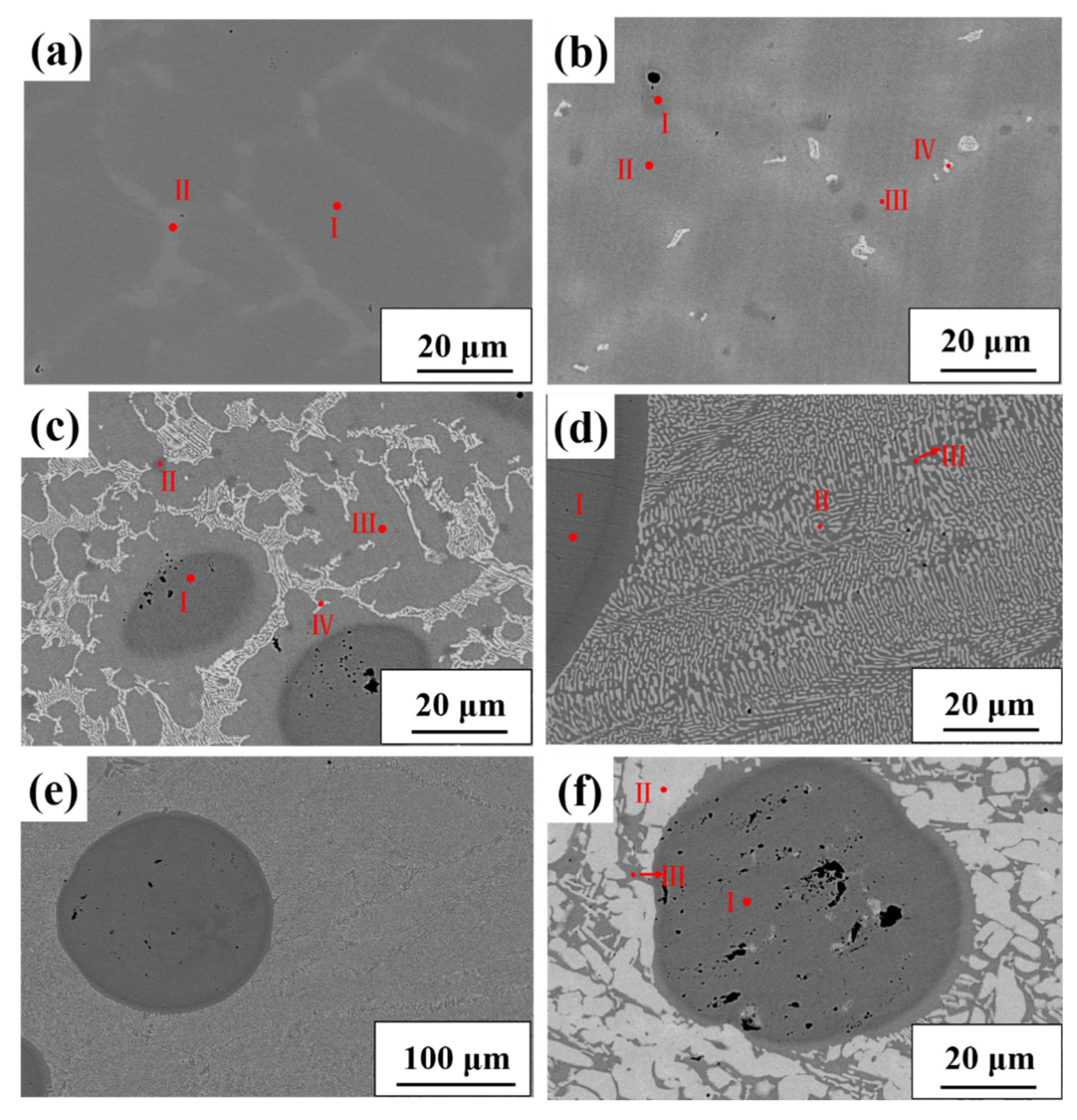
Figure 2 shows the microstructure of (CoCuFeNi)100-xMox (x = 0, 10, 15, 19, and 25) HEAs under backscattered electron (BSE) mode. The chemical compositions of various regions in the (CoCuFeNi)100-xMox HEAs are given in Table 1. The CoCuFeNi HEA exhibited obvious composition segregation, as shown in Figure 1a. According to Table 1, the bright contrast region was enriched in Cu but depleted in Co, Fe, and Ni. However, the region with dark contrast was Co-, Fe-, and Ni-rich, but Cu-depleted. Cu has mixing enthalpies with all other elements, therefore, it cannot mix with Co, Fe, and Ni [22]. Both regions corresponded to the FCC phase according to the XRD results in Figure 1.
When the Mo content was 10 at.%, there were four regions in the alloy, which was different from the CoCuFeNi HEA. The compositions of these regions were also listed in Table 1. Area I was Cu-rich and Co, Fe, and Ni-depleted, and the Cu content was even as high as 77.93 at.%. Area II was Co-, Fe-, Ni-rich and Cu-poor area instead. III contained more Mo element compared with II, and the content of Mo in IV was about 30 at.%, which was much higher than III, exhibiting brighter contrast in these four regions. Based on the analysis of the XRD results, we can speculate that the IV region corresponds to the μ phase.
By further increasing the Mo contents, the volume fractions of the brightest second phase increased and eutectic structures formed. In (CoCuFeNi)100-xMox (x = 10, 15) alloys, they formed hypoeutectic structures. For (CoCuFeNi)81Mo19, fully eutectic structures were found in this alloy. By further increasing Mo content, hypereutectic structures appeared in the (CoCuFeNi)75Mo25 alloy. According to the XRD pattern, these second phases were indexed as the μ phase. Moreover, Cu-rich spheres dispersed when more Mo was added into CoCuFeNi HEA. This phenomenon was due to liquid phase separation, which is usually reported in liquid immiscible alloys systems such as Cu-containing alloy [19,26]. The large positive mixing enthalpies between Cu and other constituent elements were considered to be the main reason for this phenomenon. It has been reported that liquid-phase separation exists in CrCuxFeMoyNi, CoCrCuxFeMoNi (x ≥ 0.5) [27], and CoCuFeNiNbx HEAs [19]. Therefore, it may be possible for the (CoCuFeNi)100-xMox alloy to occur during liquid phase separation. It has also been reported that liquid phase separation may appear in some peritectic alloys with large positive mixing enthalpies [19]. The solidification processes of such phenomenon have been studied in CoCuFeNi-Nb alloys, which showed that peritectic and eutectic reactions occurred during solidification [19]. Therefore, it may be deduced that such microstructures in (CoCuFeNi)100-xMox alloys were due to the existence of peritectic and eutectic reactions. Furthermore, compared with (CoCuFeNi)90Mo10 HEA, liquid phase separation became serious with further addition of the Mo element into CoCuFeNi.
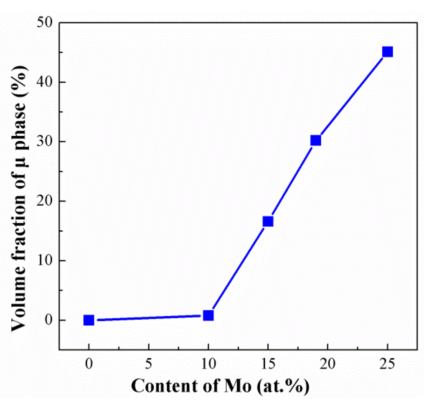
The volume fraction of the μ phase was obtained by the SEM micrograph, as shown in Figure 3. It can be seen that the content of μ phase increased with Mo addition. For the (CoCuFeNi)85Mo19 alloy with eutectic microstructure, the fraction of the μ phase was 30.2%, and the highest content of μ phase (45.1%) were obtained in the (CoCuFeNi)75Mo25 alloy. The volume fraction of brittle μ phase has an important effect on the mechanical performance of (CoCuFeNi)100-xMox alloys.
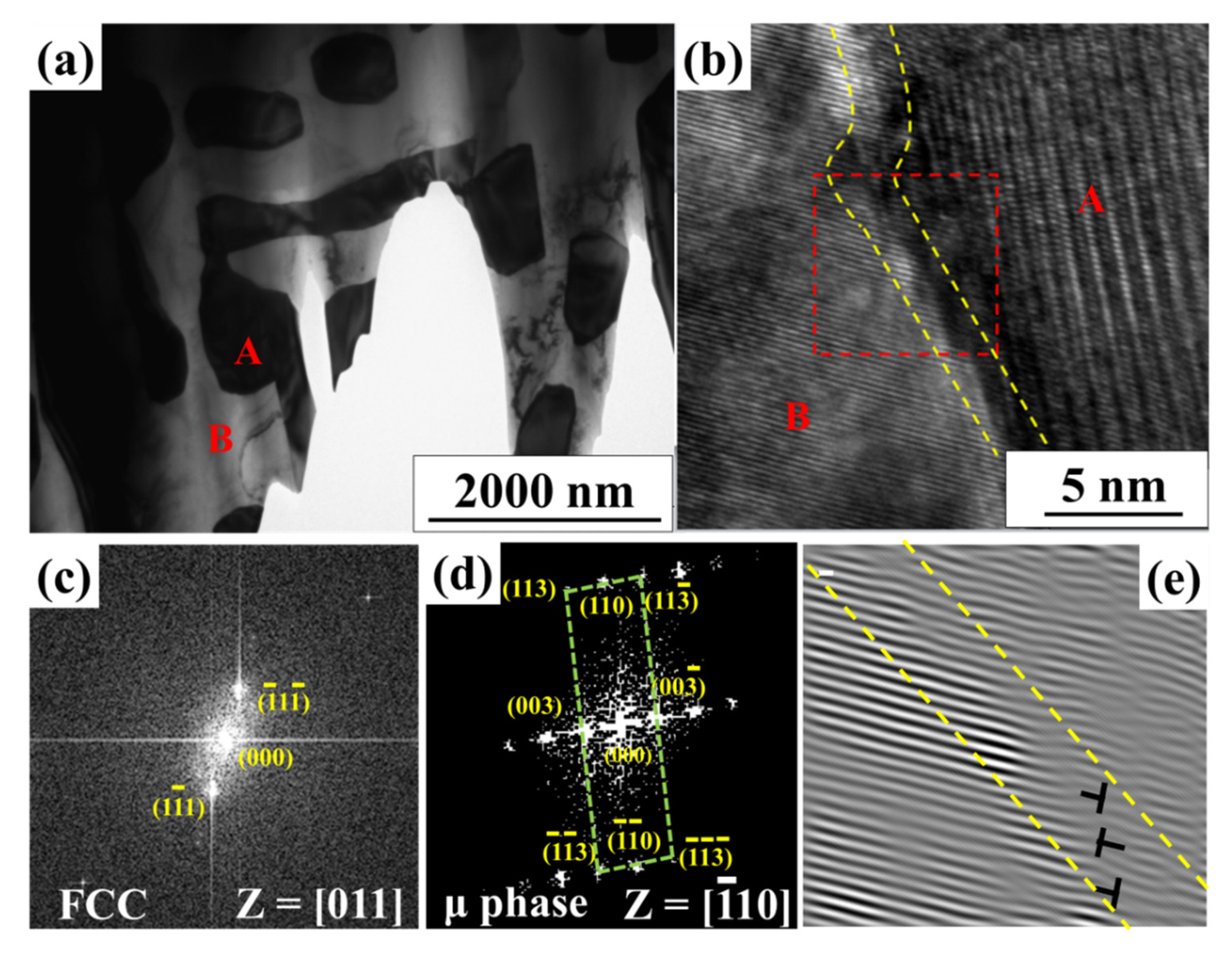
Detailed microstructure investigation for (CoCuFeNi)81Mo19 HEA was performed by TEM. Bright-field (BF) images are shown in Figure 4. Additionally, Figure 4b presents a high-resolution transmission electron microscopy (HRTEM) image of the (CoCuFeNi)81Mo19 alloy near the interface between the FCC phase and μ phase. The corresponding fast Fourier transform (FFT) images are shown in Figure 4c,d. The inverse fast Fourier transform (FFT) image, corresponding to the region of HRTEM (marked in Figure 4b by a red square) confirmed the emergence of a coherent interface between the two phases. The FCC phase and the μ phase were coherent with [110]FCC//[110]μ and {111}FCC//{113}μ. Several dislocations could be observed near the interface, which could be resulted from the lattice misfit between two different phases. Previous reports have suggested that the coherent interface can effectively hinder dislocation motion and greatly enhance the mechanical properties of alloys [28].
Several physical parameters have been used to predict the phase formation in HEAs [29,30,31,32,33] such as enthalpy of mixing (ΔHmix), configurational entropy of mixing (ΔSmix), δ (a parameter to quantify the atomic size difference) [29], electronegativity difference (Δχ) [30], valence electron concentration (VEC) [31], Ω (a parameter calculated by TmΔSmix/ΔHmix) [32] and atomic packing parameter γ [33]. It is proposed that when the parameters change in different regions, the different phases form in HEAs. A solid solution could be formed when δ, ΔHmix, and ΔSmix are in the range of δ ≤ 6.4%, −20 kJ/mol ≤ ΔHmix < 5 kJ/mol, and 12 ≤ ΔSmix ≤ 17.5 kJ/mol [29], or Ω ≥ 1.1 and δ ≤ 6.6% [32], or γ < 1.175 [33], according to different criteria. The phase evolves from FCC (VEC ≥8) to FCC + BCC (6.87< VEC ≤ 8) or only BCC (VEC < 6.87). We also calculated these parameters of the (CoCuFeNi)100-xMox HEAs, and the results are shown in Table 2. The physiochemical parameters for the elements in (CoCuFeNi)100-xMox alloys were referred from [34]. According to the above-mentioned criteria, it can be seen that the (CoCuFeNi)100-xMox (x = 10, 15, 19, 25) HEAs were expected to form only the disordered solution phase, while for the CoCuFeNi alloy, compounds could be formed. However, the experimental results above were not consistent with the calculated ones. Further investigation should be conducted to explain these differences.
3.3. Mechanical Properties
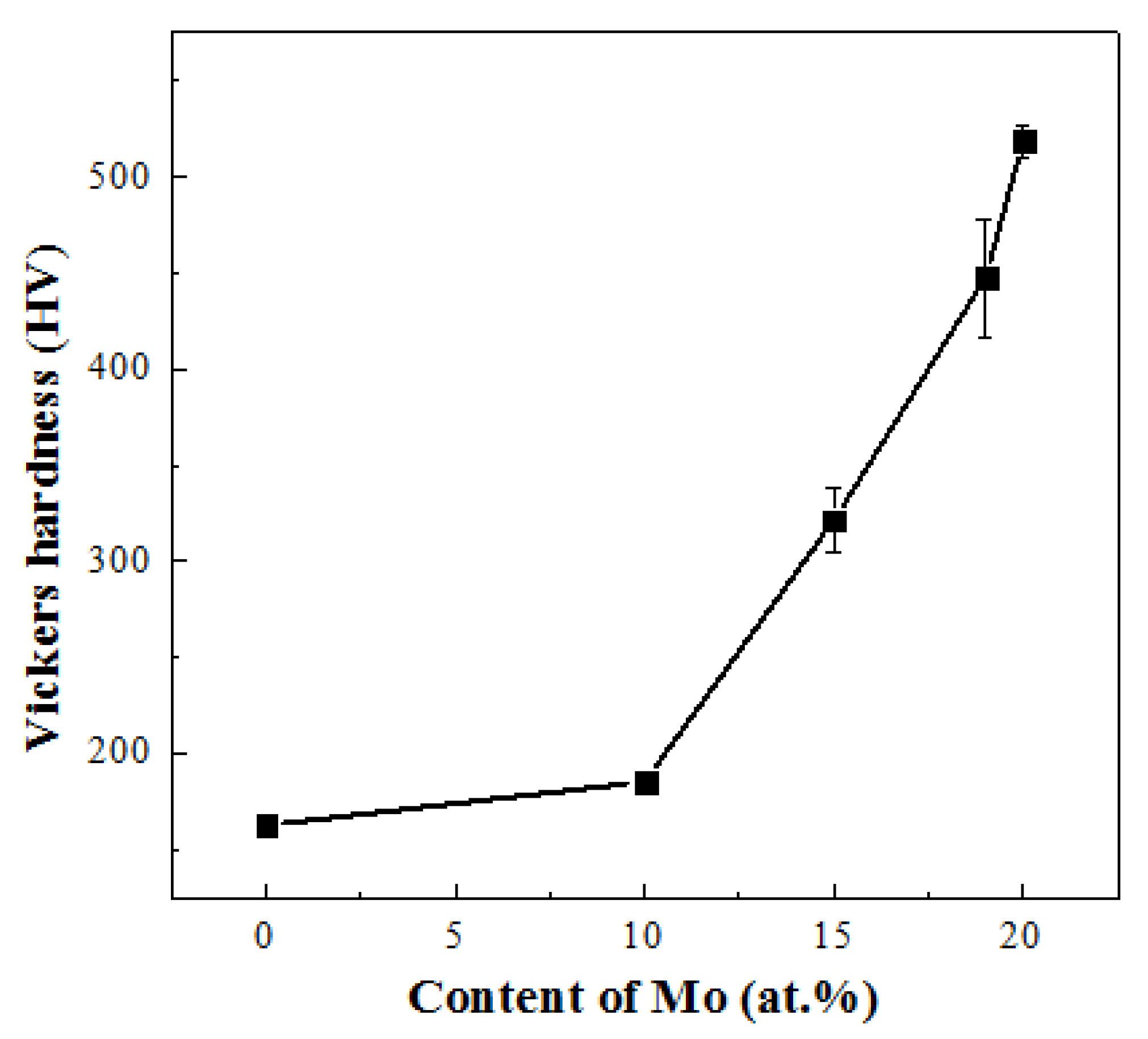
Figure 5 shows the evolution of Vickers hardness of the (CoCuFeNi)100-xMox HEAs with the Mo content. It can be seen that the hardness values increased gradually with the content of Mo. The (CoCuFeNi)100-xMox (x = 0) alloy had the lowest hardness of 162 HV. The highest Vickers hardness value of 518 HV was obtained for the (CoCuFeNi)75Mo25 alloy. The change trend of hardness was similar to that of the volume fraction of the μ phase, which means that the increase of hardness in the alloys was due to the increasing content of the μ phase.
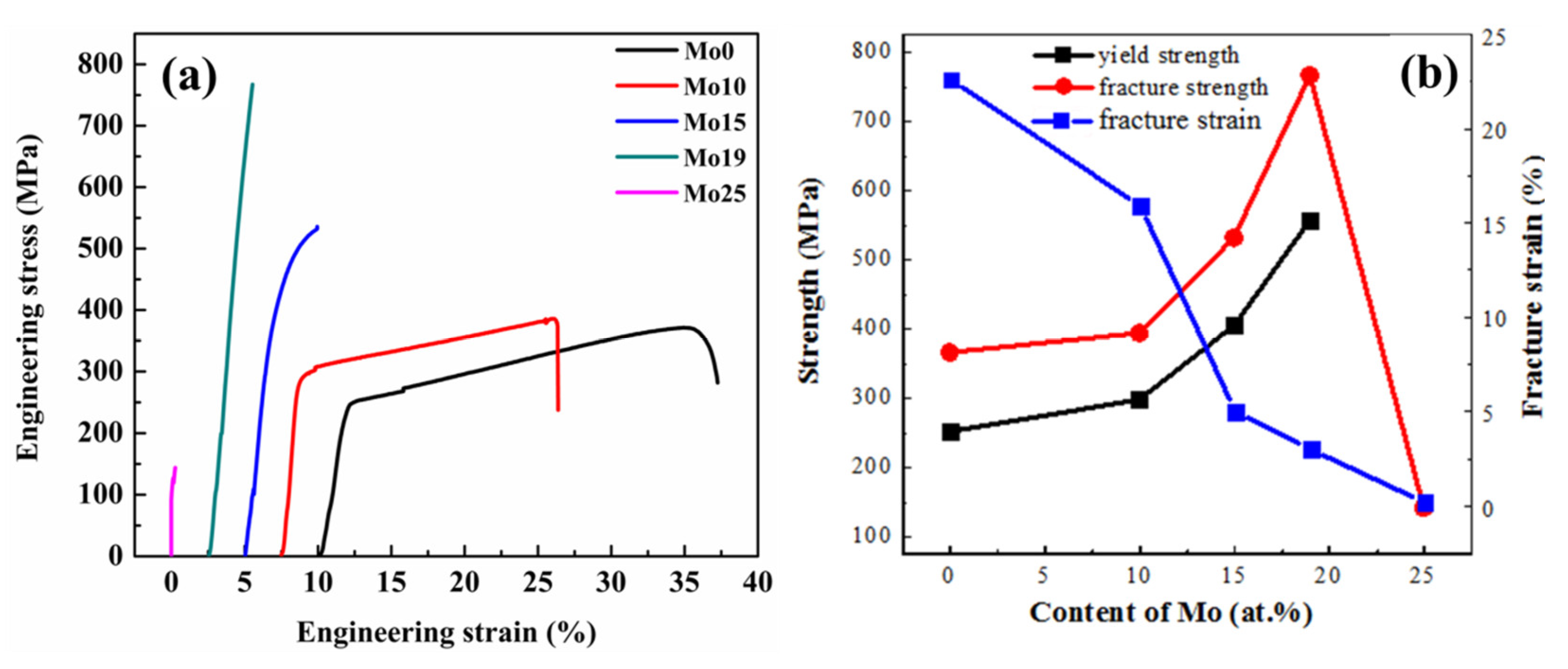
Figure 6 shows the stress–strain curves, and the curves of fracture strength, yield strength, and fracture strain of (CoCuFeNi)100-xMox alloys vs. Mo contents. It can be seen that the yield strength and strain exhibited different change trends with the increase in Mo content when x < 25. The fracture strength reached its highest value (767 MPa) when the content of Mo increased to 19 at.%. Among all the alloys investigated in this study, the tensile fracture strength of the hypoeutectic (CoCuFeNi)85Mo15 alloy reached up to 532 MPa with an acceptable elongation greater than 5%. When x = 25, due to the high content of brittle μ phase, as shown in Figure 3, the fracture strain and fracture strength were only 0.2% and 140 MPa, respectively. From the above XRD and SEM results and analysis, we can derive that the gradually increased yield strength when x changed from 0 to 19 resulted from the solution strengthening and second phase strengthening.
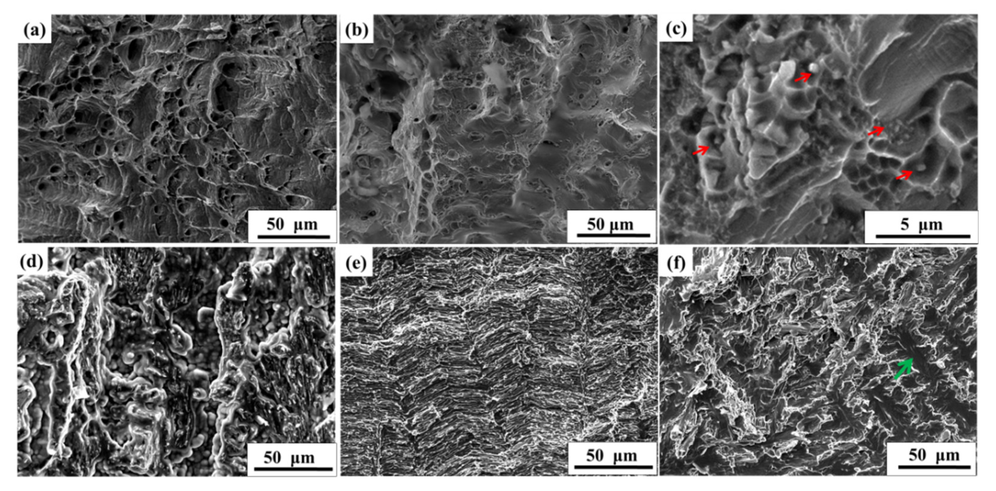
In order to further reveal the deformation behavior of (CoCuFeNi)100-xMox alloys during tensile tests at room temperature, the fracture surfaces are given in Figure 7. It can be seen from the results that the (CoCuFeNi)100-xMox alloys exhibited different fracture modes with an increase in the content of Mo. For the CoCuFeNi alloy, it displayed a fracture feature of dimples. It can be seen from the fracture morphology of the (CoCuFeNi)90Mo10 alloy that brittle intermetallic particles remained at the bottom of dimples, as indicated by red arrows. By further increasing the content of Mo, a transcrystalline fracture surface could be observed, as indicated by the green arrows in Figure 7f. Meanwhile, the transcrystalline fracture surface area increased as the content of Mo increased from 15 at.% to 25 at.%. From this, it can be concluded that as x changed from 0 to 25, the fracture diverted from a dimple fracture to a transcrystalline brittle fracture with dimple fracture. This could explain the decrease in plasticity in the tensile tests of the (CoCuFeNi)100-xMox alloys with x changing from 0 to 25.
4. Conclusions
The effect of the addition of Mo on the microstructure and mechanical properties of CoCuFeNi HEAs were investigated in detail. The results show that the phase constitution evolved from the single FCC phase to the FCC + μ phase when the Mo content increased from 0 at.% to 25 at.%. Furthermore, the Mo addition could induce liquid serious phase separation and some sphere Cu rich particles formed in the (CoCuFeNi)100-xMox alloys. The Vickers hardness increased with the content of the μ phase from 162 HV to 518 HV. The hypoeutectic (CoCuFeNi)85Mo15 alloy exhibited the best comprehensive mechanical properties. The (CoCuFeNi)81Mo19 alloy showed the highest tensile strength of 767 MPa. The FCC phase and the μ phase were coherent with [110]FCC//[110]μ and {111}FCC//{113}μ. As the Mo content increased, large amounts of the brittle μ phase formed, resulting in the fracture mode changing from a ductile dimple fracture to the manner of transcrystalline brittle fracture with dimple fracture in the (CoCuFeNi)100-xMox alloys.
Author Contributions
Funding acquisition, Y.S.; Investigation, H.M. and Y.W.; Resources, Y.S.; Writing—original draft, Y.S. and H.M.; Writing—review & editing, Y.S. All authors have read and agreed to the published version of the manuscript.
Funding
This research was supported by the National Natural Science Foundation of China (No. 51901032) and the Fundamental Research Funds for the Central Universities (Nos. 3132020152, 3132019328).
Conflicts of Interest
The authors declare no conflict of interest.
References
- Sun, S.J.; Tian, Y.Z.; Lin, H.R.; Yang, H.J.; Dong, X.G.; Wang, Y.H.; Zhang, Z.F. Transition of twinning behavior in CoCrFeMnNi high entropy alloy with grain refinement. Mater. Sci. Eng. A 2018, 712, 603–607. [Google Scholar] [CrossRef]
- Gludovatz, B.; Hohenwarter, A.; Catoor, D.; Chang, E.H.; George, E.P.; Ritchie, R.O. A fracture-resistant high-entropy alloy for cryogenic applications. Science 2014, 345, 1153–1158. [Google Scholar] [CrossRef] [PubMed] [Green Version]
- Chen, J.; Zhou, X.; Wang, W.; Liu, B.; Lv, Y.; Yang, W.; Xu, D.; Liu, Y. A review on fundamental of high entropy alloys with promising high–temperature properties. J. Alloy. Compd. 2018, 760, 15–30. [Google Scholar] [CrossRef]
- Luo, H.; Li, Z.; Mingers, A.M.; Raabe, D. Corrosion behavior of an equiatomic CoCrFeMnNi high-entropy alloy compared with 304 stainless steel in sulfuric acid solution. Corros. Sci. 2018, 134, 131–139. [Google Scholar] [CrossRef]
- Ayyagari, A.; Hasannaeimi, V.; Grewal, H.; Arora, H.; Mukherjee, S. Corrosion, Erosion and Wear Behavior of Complex Concentrated Alloys: A Review. Metals 2018, 8, 603. [Google Scholar] [CrossRef] [Green Version]
- Yeh, J.-W.; Chen, S.-K.; Lin, S.-J.; Gan, J.-Y.; Chin, T.-S.; Shun, T.-T.; Tsau, C.-H.; Chang, S.-Y. Nanostructured High-Entropy Alloys with Multiple Principal Elements: Novel Alloy Design Concepts and Outcomes. Adv. Eng. Mater. 2004, 6, 299–303. [Google Scholar] [CrossRef]
- Senkov, O.; Wilks, G.B.; Scott, J.M.; Miracle, D.B. Mechanical properties of Nb25Mo25Ta25W25 and V20Nb20Mo20Ta20W20 refractory high entropy alloys. Intermetallics 2011, 19, 698–706. [Google Scholar] [CrossRef]
- Yuan, Y.; Wu, Y.; Tong, X.; Zhang, H.; Wang, H.; Liu, X.J.; Ma, L.; Suo, H.L.; Lu, Z.P. Rare-earth high-entropy alloys with giant magnetocaloric effect. Acta Mater. 2017, 125, 481–489. [Google Scholar] [CrossRef] [Green Version]
- Laplanche, G.; Kostka, A.; Horst, O.M.; Eggeler, G.; George, E.P. Microstructure evolution and critical stress for twinning in the CrMnFeCoNi high-entropy alloy. Acta Mater. 2016, 118, 152–163. [Google Scholar] [CrossRef] [Green Version]
- Schuh, B.; Mendez-Martin, F.; Völker, B.; George, E.P.; Clemens, H.; Pippan, R.; Hohenwarter, A. Mechanical properties, microstructure and thermal stability of a nanocrystalline CoCrFeMnNi high-entropy alloy after severe plastic deformation. Acta Mater. 2015, 96, 258–268. [Google Scholar] [CrossRef] [Green Version]
- He, J.Y.; Wang, H.; Huang, H.L.; Xu, X.D.; Chen, M.W.; Wu, Y.; Liu, X.J.; Nieh, T.G.; An, K.; Lu, Z.P. A precipitation-hardened high-entropy alloy with outstanding tensile properties. Acta Mater. 2016, 102, 187–196. [Google Scholar] [CrossRef] [Green Version]
- Ma, X.; Chen, J.; Wang, X.; Xu, Y.; Xue, Y. Microstructure and mechanical properties of cold drawing CoCrFeMnNi high entropy alloy. J. Alloy. Compd. 2019, 795, 45–53. [Google Scholar] [CrossRef]
- Ma, H.; Shek, C.H. Effects of Hf on the microstructure and mechanical properties of CoCrFeNi high entropy alloy. J. Alloy. Compd. 2020, 827, 154159. [Google Scholar] [CrossRef]
- Jiang, H.; Jiang, L.; Qiao, D.; Lu, Y.; Wang, T.; Cao, Z.; Li, T. Effect of Niobium on Microstructure and Properties of the CoCrFeNb x Ni High Entropy Alloys. J. Mater. Sci. Technol. 2017, 33, 712–717. [Google Scholar] [CrossRef]
- Stepanov, N.D.; Shaysultanov, D.G.; Salishchev, G.A.; Tikhonovsky, M.A.; Oleynik, E.E.; Tortika, A.S.; Senkov, O.N. Effect of V content on microstructure and mechanical properties of the CoCrFeMnNiVx high entropy alloys. J. Alloy. Compd. 2015, 628, 170–185. [Google Scholar] [CrossRef]
- Zhang, H.; Zhang, L.; Liu, X.; Chen, Q.; Xu, Y. Effect of Zr Addition on the Microstructure and Mechanical Properties of CoCrFeNiMn High-Entropy Alloy Synthesized by Spark Plasma Sintering. Entropy 2018, 20, 810. [Google Scholar] [CrossRef] [Green Version]
- Sun, X.; Zhu, H.; Li, J.; Huang, J.; Xie, Z. High entropy alloy FeCoNiCu matrix composites reinforced with in-situ TiC particles and graphite whiskers. Mater. Chem. Phys. 2018, 220, 449–459. [Google Scholar] [CrossRef]
- Qiu, H.; Zhu, H.; Zhang, J.; Xie, Z. Effect of Fe content upon the microstructures and mechanical properties of FexCoNiCu high entropy alloys. Mater. Sci. Eng. A 2020, 769, 138514. [Google Scholar] [CrossRef]
- Rahul, M.R.; Samal, S.; Phanikumar, G. Effect of niobium addition in FeCoNiCuNbx high-entropy alloys. J. Mater. Res. 2019, 34, 700–708. [Google Scholar]
- Liu, L.; Zhu, J.B.; Zhang, C.; Li, J.C.; Jiang, Q. Microstructure and the properties of FeCoCuNiSnx high entropy alloys. Mater. Sci. Eng. A 2012, 548, 64–68. [Google Scholar] [CrossRef]
- Farraro, R.J.; Mclellan, R.B. Temperature dependence of the Young’s modulus and shear modulus of pure nickel, platinum, and molybdenum. Metall. Mater. Trans. A Phys. Metall. Mater. Sci. 1977, 8, 1563–1565. [Google Scholar] [CrossRef]
- Takeuchi, A.; Inoue, A. Classification of Bulk Metallic Glasses by Atomic Size Difference, Heat of Mixing and Period of Constituent Elements and Its Application to Characterization of the Main Alloying Element. Mater. Trans. 2005, 46, 2817–2829. [Google Scholar] [CrossRef] [Green Version]
- Liu, W.H.; Lu, Z.P.; He, J.Y.; Luan, J.H.; Wang, Z.J.; Liu, B.; Liu, Y.; Chen, M.W.; Liu, C.T. Ductile CoCrFeNiMox high entropy alloys strengthened by hard intermetallic phases. Acta Mater. 2016, 116, 332–342. [Google Scholar] [CrossRef]
- Verma, A.; Tarate, P.; Abhyankar, A.C.; Mohape, M.R.; Gowtam, D.S.; Deshmukh, V.P.; Shanmugasundaram, T. High temperature wear in CoCrFeNiCux high entropy alloys: The role of Cu. Scr. Mater. 2019, 161, 28–31. [Google Scholar] [CrossRef]
- Ma, S.G.; Zhang, Y. Effect of Nb addition on the microstructure and properties of AlCoCrFeNi high-entropy alloy. Mater. Sci. Eng. A 2012, 532, 480–486. [Google Scholar] [CrossRef]
- Munitz, A.; Kaufman, M.J.; Abbaschian, R. Liquid phase separation in transition element high entropy alloys. Intermetallics 2017, 86, 59–72. [Google Scholar] [CrossRef]
- Peng, Z.; Liu, N.; Zhang, S.Y.; Wu, P.H.; Wang, X.J. Liquid-phase separation of immiscible CrCuxFeMoyNi high-entropy alloys. Mater. Sci. Technol. 2017, 33, 1352–1359. [Google Scholar] [CrossRef]
- Lu, K. Stabilizing nanostructures in metals using grain and twin boundary architectures. Nat. Rev. Mater. 2016, 1, 16019. [Google Scholar] [CrossRef]
- Zhang, Y.; Zhou, Y.J.; Lin, J.P.; Chen, G.L.; Liaw, P.K. Solid-Solution Phase Formation Rules for Multi-component Alloys. Adv. Eng. Mater. 2008, 10, 534–538. [Google Scholar] [CrossRef]
- Dong, Y.; Lu, Y.; Jiang, L.; Wang, T.; Li, T. Effects of electro-negativity on the stability of topologically close-packed phase in high entropy alloys. Intermetallics 2014, 52, 105–109. [Google Scholar] [CrossRef]
- Guo, S.; Ng, C.; Lu, J.; Liu, C.T. Effect of valence electron concentration on stability of fcc or bcc phase in high entropy alloys. J. Appl. Phys. 2011, 109, 103505. [Google Scholar] [CrossRef] [Green Version]
- Yang, X.; Zhang, Y. Prediction of high-entropy stabilized solid-solution in multi-component alloys. Mater. Chem. Phys. 2012, 132, 233–238. [Google Scholar] [CrossRef]
- Wang, Z.; Huang, Y.; Yang, Y.; Wang, J.; Liu, C.T. Atomic-size effect and solid solubility of multicomponent alloys. Scr. Mater. 2015, 94, 28–31. [Google Scholar] [CrossRef]
- Wu, P.H.; Liu, N.; Yang, W.; Zhu, Z.X.; Lu, Y.P.; Wang, X.J. Microstructure and solidification behavior of multicomponent CoCrCuxFeMoNi high-entropy alloys. Mater. Sci. Eng. A 2015, 642, 142–149. [Google Scholar] [CrossRef]
Figure 1.
(a) X-ray diffractometer (XRD) patterns of (CoCuFeNi)100-xMox HEAs. (b) Fitting pattern of the reflection peak between 86° and 92° of (CoCuFeNi)85Mo15 HEA. (c) The detailed image of (111) peak of the face-center-cubic (FCC) phase. (d) Lattice parameter of the FCC phase vs. the content of Mo.

Figure 2.
Backscattered electron (BSE) images of (CoCuFeNi)100-xMox HEAs: (a) x = 0, (b) x = 10, (c) x = 15, (d,e) x = 19, (f) x = 25.
Figure 2.
Backscattered electron (BSE) images of (CoCuFeNi)100-xMox HEAs: (a) x = 0, (b) x = 10, (c) x = 15, (d,e) x = 19, (f) x = 25.

Figure 3.
Volume fraction of the μ phase vs. the content of Mo in (CoCuFeNi)100-xMox alloys.

Figure 4.
(a) Bright-field (BF) image for (CoCuFeNi)81Mo19 HEA; (b) the high resolution transmission electron microscopy (HRTEM) image of the interface between FCC and μ phase; (c) the fast Fourier transformation (FFT) image of the face-center-cubic phase; (d) the FFT image of the μ phase and (e) the inverse FFT image of the interface region.

Figure 5.
Vickers hardness as a function of Mo content for (CoCuFeNi)100-xMox HEAs.

Figure 6.
Tensile properties of (CoCuFeNi)100-xMox alloys at room temperature. (a) Stress vs. strain curves of (CoCuFeNi)100-xMox alloys. (b) The yield strength, fracture strength and fracture strain vs. the content of Mo.
Figure 6.
Tensile properties of (CoCuFeNi)100-xMox alloys at room temperature. (a) Stress vs. strain curves of (CoCuFeNi)100-xMox alloys. (b) The yield strength, fracture strength and fracture strain vs. the content of Mo.

Figure 7.
Fracture surface of (CoCuFeNi)100-xMox alloys in tensile tests at room temperature: (a) x = 0; (b) x = 10; (c) a high-resolution image of (b); (d) x = 15; (e) x = 19; (f) x = 25.
Figure 7.
Fracture surface of (CoCuFeNi)100-xMox alloys in tensile tests at room temperature: (a) x = 0; (b) x = 10; (c) a high-resolution image of (b); (d) x = 15; (e) x = 19; (f) x = 25.


Table 1.
Chemical compositions (in at.%) of various regions in (CoCuFeNi)100-xMox high entropy alloys.
Table 1.
Chemical compositions (in at.%) of various regions in (CoCuFeNi)100-xMox high entropy alloys.
| HEAs | Regions | Co | Cu | Fe | Ni | Mo |
|---|---|---|---|---|---|---|
| CoCuFeNi | I | 26.89 | 16.87 | 28.90 | 27.34 | 0 |
| II | 14.16 | 49.87 | 15.76 | 20.22 | 0 | |
| (CoCuFeNi)90Mo10 | I | 4.83 | 77.93 | 5.59 | 11.33 | 0.32 |
| II | 26.72 | 10.99 | 26.93 | 25.51 | 9.85 | |
| III | 24.72 | 10.31 | 24.74 | 23.81 | 16.42 | |
| IV | 22.39 | 8.45 | 20.81 | 17.80 | 30.55 | |
| (CoCuFeNi)85Mo15 | I | 3.73 | 77.30 | 4.33 | 14.61 | 0.03 |
| II | 9.51 | 62.56 | 10.31 | 13.44 | 4.18 | |
| III | 25.13 | 12.30 | 25.19 | 23.36 | 14.02 | |
| IV | 23.40 | 7.86 | 22.50 | 18.38 | 27.87 | |
| (CoCuFeNi)81Mo19 | I | 5.53 | 69.38 | 7.53 | 17.37 | 0.20 |
| II | 23.00 | 3.18 | 19.56 | 13.86 | 40.41 | |
| III | 23.71 | 10.94 | 25.02 | 25.42 | 14.91 | |
| (CoCuFeNi)75Mo25 | I | 1.66 | 86.69 | 2.48 | 8.94 | 0.23 |
| II | 20.90 | 1.47 | 18.52 | 13.79 | 45.31 | |
| III | 22.06 | 10.82 | 24.61 | 26.84 | 15.67 |
Table 2.
Parameters ΔSmix, ΔHmix, δ, VEC, ΔX, Ω for the (CoCuFeNi)100-xMox high entropy alloys.
| Alloys | ΔSmix (J/kmol) | ΔHmix (kJ/mol) | δ (%) | VEC | ΔX | γ | Ω |
|---|---|---|---|---|---|---|---|
| Mo0 | 11.53 | 5.00 | 1.18 | 9.50 | 0.0308 | 1.0348 | 3.84 |
| Mo10 | 13.08 | 4.50 | 3.32 | 9.15 | 0.0889 | 1.1328 | 5.19 |
| Mo15 | 13.31 | 4.25 | 3.85 | 8.98 | 0.1039 | 1.1325 | 5.79 |
| Mo19 | 13.38 | 4.05 | 4.18 | 8.84 | 0.1133 | 1.1322 | 6.27 |
| Mo25 | 13.32 | 3.75 | 4.55 | 8.63 | 0.124 | 1.1319 | 7.00 |
© 2020 by the authors. Licensee MDPI, Basel, Switzerland. This article is an open access article distributed under the terms and conditions of the Creative Commons Attribution (CC BY) license (http://creativecommons.org/licenses/by/4.0/).
Share and Cite
MDPI and ACS Style
Shao, Y.; Ma, H.; Wang, Y. Effect of Mo Addition on The Microstructure and Mechanical Properties of CoCuFeNi High Entropy Alloy. Metals 2020, 10, 1017. https://doi.org/10.3390/met10081017
AMA Style
Shao Y, Ma H, Wang Y. Effect of Mo Addition on The Microstructure and Mechanical Properties of CoCuFeNi High Entropy Alloy. Metals. 2020; 10(8):1017. https://doi.org/10.3390/met10081017
Chicago/Turabian StyleShao, Yang, Huan Ma, and Yibing Wang. 2020. "Effect of Mo Addition on The Microstructure and Mechanical Properties of CoCuFeNi High Entropy Alloy" Metals 10, no. 8: 1017. https://doi.org/10.3390/met10081017
Note that from the first issue of 2016, this journal uses article numbers instead of page numbers. See further details here.