Article

Low-Temperature Preparation of SiO2/Nb2O5/TiO2–SiO2 Broadband Antireflective Coating for the Visible via Acid-Catalyzed Sol–Gel Method

1
School of Science, University of Science and Technology Liaoning, Anshan 114051, China
2
Shanghai Synchrotron Radiation Facility, Shanghai Institute of Applied Physics, Chinese Academy of Sciences, Zhangjiang Campus, Shanghai 201204, China
*
Author to whom correspondence should be addressed.
Coatings 2020, 10(8), 737; https://doi.org/10.3390/coatings10080737
Submission received: 4 July 2020 / Revised: 21 July 2020 / Accepted: 24 July 2020 / Published: 28 July 2020
(This article belongs to the Special Issue Design of Functional Coatings by Chemical Methods)

Abstract

:
Multilayer broadband antireflective (AR) coatings consisting of porous layers usually suffers poor functional durability. Based on a quarter-half-quarter multilayer structure, AR coatings with dense SiO2 film as the top layer are designed, and refractive index for each layer is optimized. After heat-treated at only 150 °C, refractive index of Nb2O5 film reaches to 2.072 (at 550 nm), which can meet design requirements of the middle layer. TiO2–SiO2 composites with controllable refractive indices are selected to be used as the bottom layer. The obtained triple-layer AR coating presents excellent performance, and the average transmittance at 400–800 nm attains 98.41%. Dense layers endow the multilayer structure good abrasion-resistance, and hexamethyldisilazane is further used to modify the surface of the AR coating, which can greatly improve the hydrophobicity of the coating. The proposed triple-layer broadband AR coating has potential value in practical applications of sol–gel deposition.

1. Introduction

Broadband antireflective (AR) coatings have attracted much attention in imaging devices, solar cells, display panels and laser systems by reducing reflective losses at interfaces over a broad range of wavelengths [1,2,3,4]. AR coatings derived from sol–gel process have good potential for practical applications due to its powerful control on the structure and properties of films, low cost and abilities to deal with substrates of large area and/or complex shapes [5,6,7]. An effective 0% reflection can be achieved at a specific wavelength when a single-layer quarter-wave silica AR coating is applied onto flat substrates using the sol–gel method. The porosity between based-catalyzed silica colloid particles or acid-catalyzed silica linear oligomers lowers the refractive index of silica AR coating to the square root of the index of such optical substrates as fused quartz (1.46) and BK7 glass (1.52), i.e., approximately 1.22 [8,9,10,11]. Based on optical theory, the realization of broadband AR coatings needs to establish multilayer film structures, in which the refractive index and thickness of each layer must be carefully adjusted. Precedent studies have shown that, if a mesoporous film with ultralow refractive index of 1.22 or even smaller is used as the top layer, this is very helpful for improving the optical performance of broadband AR coatings [4,12,13,14,15]. However, porous structure of film would probably give rise to the problems such as poor mechanical strength and degraded performance due to the adsorption of contaminants [16,17,18,19]. Even if many anti-pollution techniques have been developed, it is difficult to ensure mechanical strength and durability of AR coatings with porous structure [20]. For these issues, silica film derived by acid-catalyzed sol–gel method is an alternative material as the top layer. Finer ramified polymeric siloxane chains formed under low pH conditions further crosslink by evaporation of the solvent, causing the refractive index of dense silica film to be about 1.44 [21,22]. For silica film with no nanoscale pore openings, it is relatively easy to implement surface functionalization for improving film contamination-resistant performance.
The refractive indices of multilayer materials need to be fitted for the realization of broadband AR coatings. According to the theory of multilayer design, triple-layer interference films with quarter-half-quarter wavelength in optical thickness (i.e., λ/4-λ/2-λ/4) can provide consistent high transmittances in a broad region and do not require the top layer with very low refractive index [20]. For the triple-layer AR coating, the reflectance at the central wavelength λ0 will be zero if
nM2 = nL2nS
where the subscripts M, L and S correspond to the bottom layer, the top layer and the substrate, respectively. In order to further broaden antireflection spectral range, a half-wave middle layer is introduced, and its refractive index should satisfy the following condition
nH > nM2/nS
where the subscript H denotes the middle layer. The film structure of the multilayer coating can be denoted as S|M2HL|A, in which A is the air, M and L are a convenient shorthand notation for quarter-wave optical thicknesses, 2H is for half-wave optical thickness. For the triple-layer coating applied onto fused quartz, the proper refractive index of M layer is 1.74, and that of H layer should be larger than 2.07. High index oxide gel materials are usually prepared from zirconium or titanium alkoxides. Nevertheless, porous network structure caused by the crosslink of sol particles during the sol–gel transition will lead to a low packing density and then a low refractive index of film [23]. In addition, the obtained gel films exhibit an organic–inorganic hybrid structure caused by the use of organic ligands for controlling hydrolysis and condensation of zirconium or titanium with high reactivity, resulting in another decrease in the refractive index of film. High temperature treatment at even above 300 °C can obviously increase the refractive index of film for meeting the requirement of the above-mentioned H layer, but meanwhile it leads to remarkable energy consumption in quantity film production. Hence, it is necessary to explore the preparation of gel oxide films with high refractive index at a relatively low heating temperature below 200 °C. Many efforts have been focused on high index titania (TiO2) films, while it is still quite difficult to simultaneously achieve high stability of sol and high performance of gel film [24,25,26,27]. In addition, stress incompatibility between different layers mainly related with surface tension of high index titania [28,29] must be alleviated. Niobium pentoxide (Nb2O5) film may be an alternative choice, as niobium is less active than titanium and Nb2O5 is a potential optical film material for the visible and near-infrared spectral ranges similar to titanium oxide [30]. Because niobium alkoxides are quite expensive and highly sensitive to moisture, procedures for obtaining Nb2O5 gel film from niobium salt NbCl5 have been developed [31,32,33]. In this study, a modified sol system derived from NbCl5 has been developed for preparing the H layer of the multilayer AR coating.
M layer composed by single component material may face mismatching of refractive index since it will inevitably be heat-treated along with H layer. Thus, composite films with tunable refractive index play a key role for assembling a good broadband AR coating. Louis et al. successfully obtained TiO2–SiO2 binary films using titanium tetrachloride (TiCl4) and tetraethyl orthosilicate (TEOS) as a starting material, and the refractive index of the composite material can be accurately adjusted between 2.20 and 1.45 through modulating thermal treatment and composition [26]. In their system, protons prevented titanium oxo–hydroxide precipitation. Recently, TiO2–SiO2 hybrid films have been increasing studied due to their significant potential for applications in functional AR coatings [20,34,35,36]. There have been two synthetic routes for preparing TiO2–SiO2 composite sols. The first is direct mixing of separately synthesized TiO2 sol and SiO2 sol. However, it is generally difficult for this approach to guarantee the long-term stability of the mixed binary sol because of the remarkable difference in hydrolysis activity between titanium and silicon. The other is in situ mixing of titanium and silicon precursors such as TiCl4 and TEOS, and this work tends to employ the latter route to obtain stable binary sols by introducing a prehydrolysis step of TEOS.
The present work is devoted to fabricating SiO2/Nb2O5/TiO2–SiO2 AR coating by the sol–gel process. Refractive index of the top layer was first set to be constant, and then refractive indices of the other two layers were optimized for the quarter-half-quarter coating with the aid of thin film design software (Filmstar). Nb2O5 film heat-treated at 150 °C resulted in the required high refractive index of the middle layer, and TiO2–SiO2 hybrid films were selected as the bottom layer for optimal combination based on the theoretical design. Substrates (fused quartz) coated with the triple-layer films achieved the average transmittance of 98.57% at the entire visible region. The multilayer AR coating was immerged in hexamethyldisilazane (HMDS) solution to improve surface hydrophobicity.

2. Experimental Section

2.1. Preparation of Sols and Films

Materials: TEOS (98%) was purchased from Acros, Shanghai, China. NbCl5 (99%) was purchased from Innochem. TiCl4 (99%) was purchased from Alfa, Shanghai, China. Hydrochloric acid was purchased from Shenyang Chemicals, Shenyang, China. Anhydrous ethanol and glacial acetic acid were purchased from Beijing Chemicals, Beijing, China. All chemicals were used without further purify action.
Preparation of acid-catalyzed SiO2 sol: The silica sol was prepared using TEOS as precursor under acidic conditions. The molar ratio in the solution was set to 1 TEOS:30 EtOH:7 H2O:0.02 HCl. The newly mixed solution was stirred for 12 h and then aged at room temperature for 15 days before further use. The silica precursor sol is stable for at least two months.
Preparation of Nb2O5 sol: The synthesis of Nb2O5 sol was modified according to the literatures [31,37]. NbCl5 was first, dissolved in anhydrous ethanol containing acetic acid, and the mixed solution was sealed and stirred for 30 min. Hydrolysis and condensation were then carried out by adding another part of anhydrous ethanol containing deionized water into the solution, leading to the formation of fresh sol. The molar ratio of NbCl5, acetic acid, H2O and EtOH is 1:0.5:2:105. The sol was finally filtered through a 0.22-mm PVDF filter prior to use. The Nb2O5 sol was aged at the room temperature and can be stable for about 20 days.
Preparation of TiO2–SiO2 composite sol: The TiO2–SiO2 composite sols were prepared according to the literatures [26,38]. In this study, the total number of moles of TiCl4 and TEOS for each TiO2–SiO2 hybrid sol was set to be constant (0.0454 mol), and three composite sols were synthesized with different Ti/Si ratio of 30/70, 33/67, 36/64. During the synthesis of the composite sols, two different solutions were prepared. A typical procedure corresponding to the Ti/Si ratio of 33/67 is given as an example. In the first part, TEOS, HCl, H2O and EtOH at the molar ratio of 1:5 × 10⁻⁵:1:3 were mixed and stirred at 60 °C for 2 h to achieve an instantaneous hydrolysis, but slow condensation. Afterwards, the mixed solution was added into 46 mL of anhydrous ethanol with 1.24 g of deionized water and 75 μL of hydrochloric acid (37%), and then kept stirring at the room temperature for 30 min. The second part of the sol was prepared by dissolving 2.84 g of TiCl4 in 60 mL of anhydrous ethanol containing 0.45 g of acetic acid. The controlled hydrolysis–polycondensation was carried out by rapidly mixing the two solutions under vigorous stirring, leading to the formation of fresh sol. The molar ratio in the initial solution was set to x TiCl4:(1 − x) TEOS:0.5x acetic acid: 40 EtOH:2 H2O:0.02 HCl. To simplify discussion, both the TiO2–SiO2 hybrid sols and the corresponding films were noted as T30S70, T33S67 and T36S64 according to the molar ration of the converted TiO2 and the converted SiO2. The TiO2–SiO2 composite sols are stable for about two months.
Preparation of triple-layer AR coating: The films were deposited via dip coating on well-cleaned quartz substrates. The dip speed was precisely set to control film thickness. For the coating with a certain refractive index, the theoretical transmittance spectrum can be obtained for a certain thickness. The experimental single-layer film satisfying the requirement of design model can be chosen by comparing the measured spectrum with the theoretical spectrum. This approach is especially useful for dense SiO2 film because its spectrum only presents a gentle single-peak.
During deposition of the triple-layer AR coatings, TiO2–SiO2 hybrid film and Nb2O5 film were successively deposited on quartz substrate. Each as-deposited layer was heated at 80 °C for 2 min in a drying oven to accelerate solvent evaporation. The deposition of the Nb2O5 film should be repeated twice to obtain the required film thickness, which can avoid excessively high dip speed. Afterwards, the first two layers were heat-treated at 150 °C for 1 h in the oven. In the end, the SiO2 film was deposited to accomplish the assembly of the triple- layer coating. The AR coatings were placed for 12 h in a closed container and then characterized.
Surface modification: HMDS (15 mL) was dissolved in ethanol (50 mL), and this surface of the AR coating was modified by the reaction of HMDS with surface hydroxyl group via dip-coating at 200 μm s−1. The durability of the surface-modified coating was evaluated by measuring the transmittance change of the AR coating fixed on a quartz sample holder and placed in normal air environment for several months. Ambient temperature and relative humidity changed in the scope of 10–30 °C and 20%–50%, respectively.

2.2. Characterization of Sols and Films

Transmittance spectra were measured using an ultraviolet/visible/near-infrared (UV-Vis/NIR) spectrometer (Shimadzu, UV3600 plus, Tokyo, Japan) over the wavelength range of 300–1400 nm. The refractive indices and thicknesses of thin films obtained by fitting the transmission spectra provide a foundation for the design and preparation of the multilayer structure coating.
Small-angle X-ray scattering (SAXS) experiments were done on the precursor sols at the BL16B1 beamline of the Shanghai Synchrotron Radiation Facility. The wavelength of the X-ray was 0.124 nm. The 2D SAXS patterns were recorded by Pilatus 1 M with the single pixel of 1.72 × 10⁻⁴ m. The distance between the sample and the detector was 1.6 m. The SAXS intensity patterns were corrected for background scattering and then radially integrated into one-dimensional scattering intensities I(q), where q is the magnitude of the scattering wave vector. The FTIR spectra of the samples were studied using Cary 630 infrared spectrophotometer. Film surface morphology was investigated with a CSPM5500 AFM (Benyuan, Guangzhou, China). The mechanical durability of the obtained coating was assessed in the abrasion test, in which the coating was rubbed for 50 cycles via a 3H pencil and the controlled normal stress on coating surface was about 30 kPa. Scratches caused by rubbing were scanned by an optical microscopy (Nexcope, NM900, Ningbo, China). Contact angles were measured on a contact angle goniometer (Shanghai Zhongchen, JC200 °C, Shanghai, China).

3. Results and Discussion

3.1. Computer-Aided Design of Triple-Layer AR Coating

Generally, the optical constants for a material will vary for different wavelengths. In addition, thickness and refractive index requirements for each layer of multilayer broadband AR coatings make film design rather complex. It is fortunate that refractive index dispersion is low for most oxide films in the visible and near-infrared regions. In the initial stage of coating system design, it is feasible to perform calculations while temporarily ignoring refractive index dispersion, and then select the results best suited for a given application. The design of the λ/4-λ/2-λ/4 triple-layer AR coating was implemented by the thin film design software Filmstar (2.61.3921). The optical thicknesses of the layers are defined with respect to the central wavelength λ0 = 550 nm. The optimization process needs to minimize the objective function for the visible wavelengths, i.e.,
f = 1 N i = 1 N | T ( λ i ) 1 | ,   ( in   the   range   of   400 800   nm )
where T(λi) is the calculated transmittance at wavelength λi. In the latter section T(λi) also denotes the experimental transmittance, and then the optical performance of the coating can be evaluated through the corresponding f value. As dense SiO2 gel film with a refractive index of 1.44 is selected as the top layer for the AR coating on fused quartz substrate, the optimized refractive index of the bottom layer nM can be obtained for each number point of nH, and the values of f are calculated from the theoretical transmittances of each optimized coating system, as shown in Figure 1. With nH increasing from 1.9 to 2.08, a monotonic increase of nM from 1.59 to 1.65 is found, and the values of f dramatically decrease to 0.009. Afterwards, the variation tendency of f slows down with nH continuously increasing to 2.14. It is worth mentioning that, while nH is greater than 2, the average transmittance in the range of 400–800 nm can exceed 99%. Note that the optimized values of nM deviate from the theoretical value according to Equation (1), which is necessary for achieving a broad region of low reflection rather than only at the central wavelength.

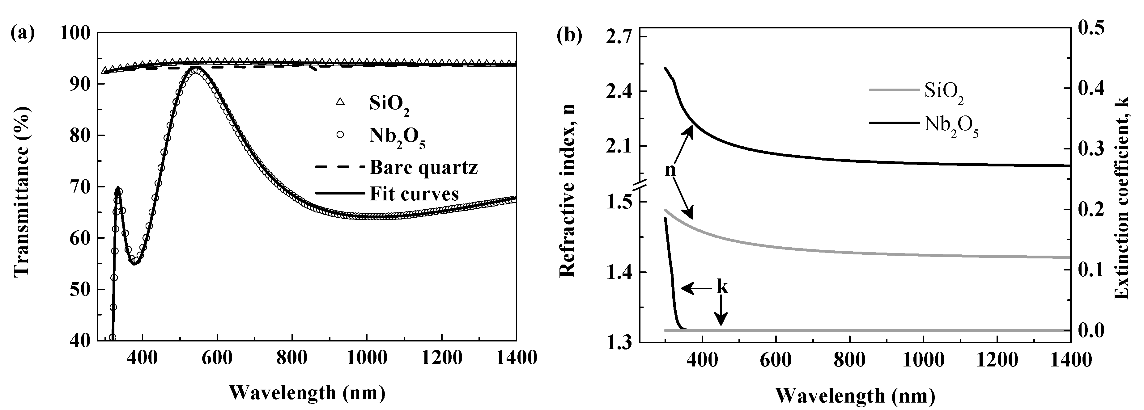
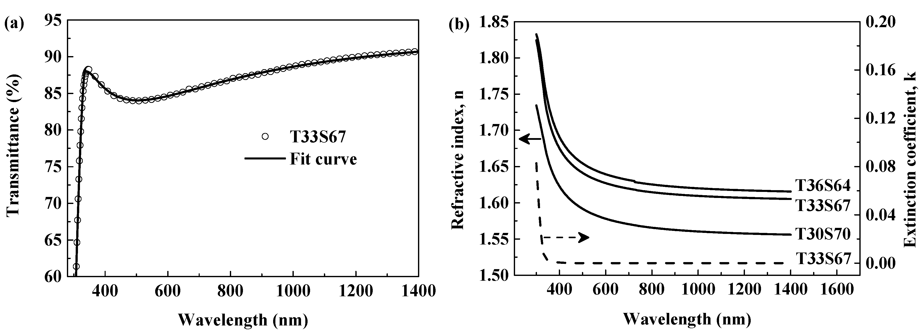
3.2. Optical Properties of Films SiO2 and Nb2O5

Rational design of multilayer AR coatings must be based on accurate analysis of optical properties of film materials. Optical transmittance provides accurate and quick information for optical coatings deposited on transparent substrates. By adopting appropriate dispersion models, film transmittance data can be well fitted in the range from ultraviolet to near-infrared for the retrieval of refractive index n and extinction coefficient k [39,40,41]. The Cauchy equations [39] can be well suited to model the nearly transparent film SiO2 in the whole current spectral region. In order to comprehensively study optical properties of Nb2O5 and TiO2–SiO2 films, this work tends to employ oscillator models to expand the scope of transmittance spectrum analysis to the UV region. For amorphous semiconductor materials, the Cody–Lorentz model can effectively characterize the physical characteristics of films in interband transitions [41,42]. In addition, bandwidth of Urbach tail [43] is introduced to modify the dielectric constants nearby the optical band gap.
The fit of the calculated spectra to the experimental data have been made for the single-layer films with the help of a fitting program in Matlab (9.3.0.713579, 2017b) [36]. The program can find the calculated spectrum closest to the measured data by combing the genetic algorithm and the lsqcurvefit algorithm through adjusting fitting parameters, such as film thickness and optical constants. The calculated curves of films SiO2 and Nb2O5 in the spectral region of 300–1400 nm are shown in Figure 2a, which are in good agreement with the measured transmittance. In fact, the difference between transmittance data of film SiO2 and that of bare quartz at each wavelength is less than 1.1%, implying that the SiO2 film obtained under the acid-catalyzed condition is highly dense even without any heat treatment. Meanwhile, multiple interference fringes can be found in the transmittance spectrum of film Nb2O5. The decrease of transmittance of the Nb2O5 film near the left wavelength boundary of the measurement region is obviously connected with high absorption of the film because the quartz substrate is still transparent in that region. The achieved optical constants of the films are depicted in Figure 2b. The refractive indices of films SiO2 and Nb2O5 at 550 nm are 2.072 and 1.439, respectively, which can reach the requirements of the multilayer AR coating for the top layer and the middle layer. It can be seen that the degree of index dispersion of film Nb2O5 is obviously higher than that of film SiO2. In the visible region, the Nb2O5 film exhibits a rather low absorption analogous to the SiO2 film, which can be attribute to the transparency and homogeneity of Nb2O5 film [30]. In addition to film optical constants, film thickness can also be determined through transmittance spectrum analysis. As such, the dip rate of the substrate can be nicely controlled until the optical thickness of the single-layer film meets the need of the designed multilayer structure.

3.3. Selection of TiO2–SiO2 Hybrid Materials for Bottom Layer

SAXS is a powerful tool for obtaining the internal structure of sol that can directly impact film optical performance. Figure 3 illustrates the scattering curves I(q) of the TiO2–SiO2 precursor sols in a log–log plot. For comparison, the scattering curve of the Nb2O5 sol is also shown. It can be seen that the scattering profiles of the TiO2–SiO2 hybrid sols exhibit a power law decay for two wave vector ranges 0.22 < q < 0.35 nm−1 and 0.35 < q < 1 nm−1. In contrast, the scattering curve of the Nb2O5 sol appears only a power law region from 0.16 to 0.3 nm−1.
In order to retrieve necessary structural information, all the scattering curves were fitted by using the Beaucage model, in which a unified equation for the scattering intensity I(q) has been proposed by Beaucage [44]. The software SasView 5.0.1 was used to obtain the fits to the Beaucage model. In this model, one structural level pertains to a Guinier-like regime, describing an average structural size in terms of radius of gyration and a structurally limited power law regime describing the mass—or surface fractal scaling for that level structure [45]. Notably, the Beaucage model is applicable for hierarchical systems composed of ‘n’ structural levels [44]. As shown in Figure 3, the data of the TiO2–SiO2 sols are fitted to two structural levels, and those of the Nb2O5 sol are to single structural level. The evaluated parameters of Radii of gyrations Rg and the power law exponents P are listed in Table 1. For the Nb2O5 sol, the fractal dimension is given by df = P = 2.68, indicating that the interconnection between the colloidal particles produces mass fractal clusters [29,45]. As for the TiO2–SiO2 sols, the subscript 2 denotes the scattering from the small titania–silica clusters, and the power law exponents P2 are lower than 1.5, corresponding to the power-law exponent of the rodlike subchains [46]. On the lager structural level 1, the scattering profiles display a power law decay of P larger than 2.9, indicating that TiO2–SiO2 particles form compact fractal structure with a diffuse interface with the rest of the system [45,47]. Further, the calculated sizes of the TiO2–SiO2 structures are comparable with the particle size in the Nb2O5 sol.
The TiO2–SiO2 hybrid films have the same ingredients; Figure 4 typically illustrates the FTIR spectrum of film T33S67. For comparison, TiO2 gel material was prepared via a synthetic route similar to that mentioned in 2.1, and the FTIR spectra of the pure SiO2 and TiO2 films are also shown in Figure 4. The broad peak around 3433 cm−1 corresponds the O–H stretching vibration and an O–H bending vibration of water molecule is also observed at 1630 cm−1 as KBr salt tablets are easy to absorb water. The absorption bands at 1066 and 790 cm−1 can be attributed to the Si–O–Si asymmetric stretching and symmetric stretching vibrations, respectively [20]. Meanwhile, the Ti–O stretching vibration is also observed from the strong and broad absorption band around 435 cm−1 [48]. It should be noted that, in the SiO2 spectrum, the peak near 450 cm−1 is attributed to the bending vibrations of Si–O–Si bonds. Besides, the low intensity band at 580 cm−1 due to residual four-membered siloxane rings in the silica network [49] is obvious only in the pure silica spectrum. Furthermore, the broad bands between 400 and 800 cm−1 in the TiO2 spectrum are associated with Ti–O–Ti network. Thus, the bands corresponding to Ti–O groups in the TiO2–SiO2 hybrid films are readily confused by Si–O–Si and Si–O groups. In contrast with the absorption at about 950 cm−1 assigned to the Si–OH observed in the SiO2 film, the presence of absorption band at 939 cm−1 in TiO2–SiO2 film can be assigned to the deformation of SiO4 tetrahedra by the formation of Si–O–Ti bonds [50,51,52], indicating in situ hybridization of the two inorganic precursors in the hybrid sols. It is well known that the hydrolysis of precursors is incomplete, and the condensation reactions tend to proceed at the end of the chain (–OH produced from hydrolysis) rather than at the middle (–OR) under acid conditions [20]. Hence the obtained polymers are linear chain network with a low degree of condensation. Figure 5 shows the TEM image of TiO2–SiO2 hybrid film, from which no obvious nanoparticles or nanopores are observed. Such linear polymeric features with a low fractal dimension (SAXS results listed in Table 1) are essential to the production of highly dense amorphous thin films [25]. Therefore, it can be speculated that the optical properties of the hybrid films are directly dependent on the relative proportions of the two precursors of TiO2 and SiO2.
The transmittance spectra of the TiO2–SiO2 hybrid films were fitted based on the Cody–Lorentz model. The experimental and calculated data of film T33S67 are representatively shown in Figure 6a. The dispersion curves of the refractive index n and the extinction coefficient k obtained from the Cody–Lorentz model are given in Figure 6b. Table 1 also lists the refractive indices at 550 nm and the extinction coefficients at 450 nm of the TiO2–SiO2 hybrid films. As expected, increasing the TiO2 molar fraction from 30% to 36% leads to a slight increase of film refractive index. The curves of the extinction coefficients of the TiO2–SiO2 films are very close to each other, and the results of film T33S67 are typically plotted in Figure 6b. The TiO2–SiO2 hybrid films exhibit weak absorption in the visible region, which is beneficial for realizing high performance of the AR coating. On the basis of the data of films SiO2 and Nb2O5, the design software Filmstar employed the series of optical constants n (λ) and k (λ) of different TiO2–SiO2 films to obtain the objective function values f for the respective optimized design models (Table 1). The results show that the objective function f for film T33S67 is the minimum (0.0109), but it is still greater than that (0.009, at nH = 2.08) of the theoretical design ignoring dispersion of film optical constants (Figure 1). In fact, there is very small difference between the values of f for T33S67 and T36S64 (listed in Table 1). Through investigating the actual performance of the corresponding multilayers, the film T33S67 was eventually chosen to assemble the triple-layer AR coatings.

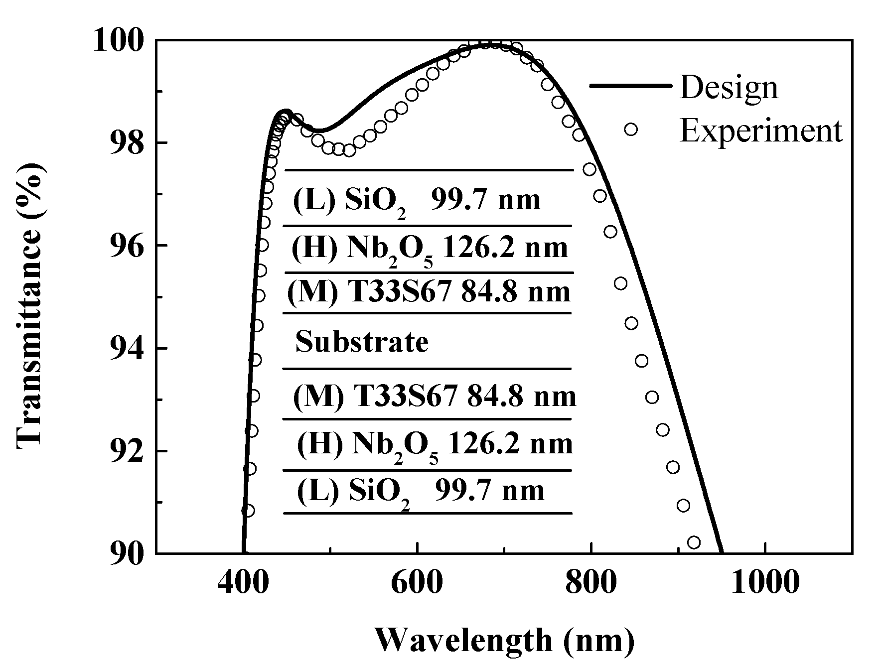
3.4. Assembly of Triple-Layer Broadband AR Coating

By importing the refractive indices and extinction coefficients of the selected single-layer films into the design software Filmstar, the thickness for each layer of the AR coating was automatically adjusted for achieving the optimized multilayer structure. Afterwards, the dip rate for each layer was nicely explored by comparing theoretical and experimental transmittance spectra of single-layer film. The optimized dip-coating speeds for individual layers are 2023, 4900 (repeat twice) and 2200 μm/s for bottom, middle and top layers, corresponding to the film thicknesses of 84.8, 126.2 and 99.7 nm, respectively. Based on the design model and the control strategies in the deposition cycle, the triple-layer AR coating can be constructed layer-by-layer.
Figure 7 presents the measured transmittance spectrum of the AR coating in the spectral range of 300–1000 nm; the inset is the schematic illustration of the triple-layer two-sided AR coating. The average transmittance of the experimental AR coating in the region of 400–800 nm is 98.41% and especially the transmittance is above 99% from 600 to 750 nm. The close correspondence between the measured and design spectral curves mainly benefits from the accurate determination of film optical parameters and the precise control of film thickness in the whole process of coating production. Compared with the transparent conductive oxides such as TEC8, TEC15 and Asahi U [53], the triple-layer oxide AR coating proposed in this study can afford lower reflectance in the visible region. Thus, the high transparent nonconductive oxides are more suitable for the production of AR coatings if only optical performance is concerned.
By substituting the experimental transmittance data into Equation (3), the obtained f is 0.0159, which is greater than that of the optimized theoretical design (0.0109, Table 1). It can be seen that the measured data slightly lower with theoretical values in the visible and near-infrared ranges, which probably results from the rough surface and interfaces in the multilayer [4]. Figure 8 shows the AFM images and root-mean-square roughness (Rq) values of bottom layer, middle layer, top layer and triple-layer coatings, respectively. The top layer and middle layer have rather smooth surface with low Rq values of 0.37 and 0.26 nm, whereas the bottom layer has a relatively larger Rq value of 2.84 nm. One can observe that, in the middle parts of visible region, all the differences between theoretical experimental transmittances are less than 1%. Taking into account the interface properties of thin films and multilayers, Tikhonravov et al. [54] have introduced approximate equations to quantitatively calculate transmittance spectra and the results manifest that the accumulation of the roughness may bring about a noticeable decrease of transmittance for multilayer structures. Fortunately, the Rq value of the surface of the triple-layer AR coating is only slightly larger than that of the single-layer SiO2 film. Thus, it is reasonable to presume that the accumulative effect between the multiple layers is very limited so that the surface and interface scattering has a rather weak impact on the transmittance data of the AR coating.
It can be seen that, for the triple-layer AR coating, there are two peak points both in the measured and theoretical spectra (shown in Figure 7), and the transmittance data near the first peak point in the range of 400–500 nm are generally lower than those near the latter peak point of about 650 nm. The results obtained from the fitting of the single-layer films show that absorption of films SiO2 and Nb2O5 is almost negligible in the whole visible region, but film T33S67 exhibits weak absorption in the spectral range of 400–500 nm (Figure 6b and Table 1). Nevertheless, the calculated spectrum is almost unchanged when setting the extinction coefficients of all the films to be zero. Therefore, under the precondition of nice control of film thickness, the relatively poor performance of the experimental coating in the spectral range of 400–600 nm is probably caused by the mismatching of layer refractive indices with different dispersion characteristics in the multilayer systems. In practice, the refractive index matching for special working wavelengths is also a major concern and challenge during the production of broadband AR coatings [4,13,55,56]. In order to identify the roles of each individual layer in the triple-layer AR coating, two types of double-layer AR coatings were prepared and the experimental transmittance spectra are shown in Figure 9. The λ/4-λ/4 AR coating can only give maximum transmittance at one wavelength, confirming that the H layer in the triple-layer AR coating effectively broadens the antireflection spectral region. In absence of the M layer, the transmittance spectrum of the λ/2-λ/4 coating gives maxima for two separate wavelengths and a minimum between the two wavelengths, which is far away from a wider region of high performance. Therefore, both the H layer and the M layer are essential for the broadband AR coating if dense low-index layer is chosen as the top layer (L layer). Conversely, by using ultralow index materials as the top layer, the number of layers of broadband AR coating can reduce to only two layers or its high performance can cover from visible to near-infrared wavelengths [4,12].

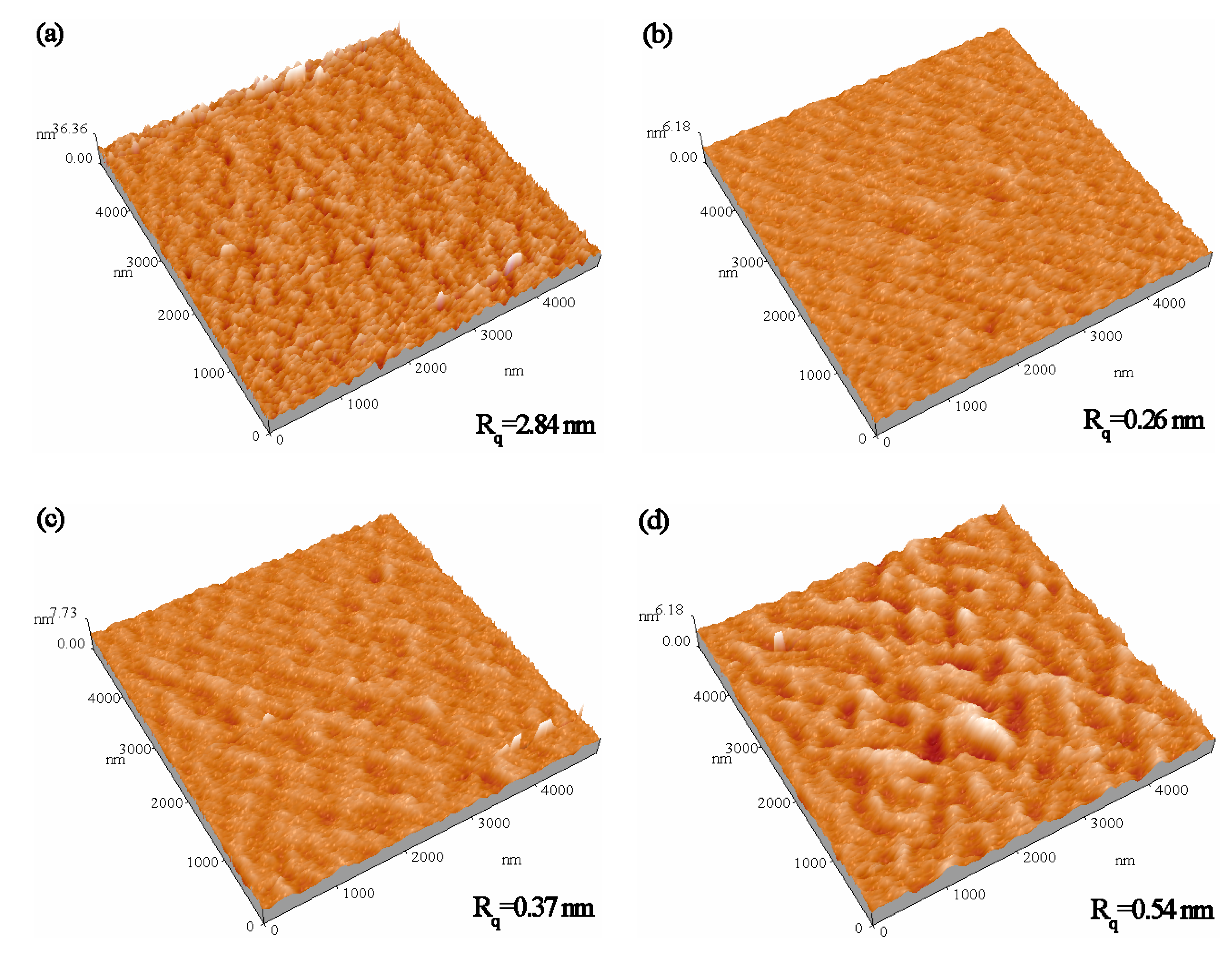
3.5. Durability Performance

As mentioned earlier, the acid-catalyzed silica sol derived coating has no nanoscale pores, and the refractive index of the obtained gel material is close to that of the bulk material. Thus, the dense silica coating can be used as an ideal material due to its low refractive index, excellent abrasion-resistance and good durability [35]. Moreover, both the Nb2O5 and TiO2–SiO2 coatings used in this work are also compact. Thanks to the above advantages of each layer in the triple-layer AR coating, repeated rubbing via a 3H pencil only leaves subtle scratches on the AR coating surface as shown in Figure 10a. Consequently, the average transmittance of the AR coating before and after rubbing test has a very small decrease from 98.41% to 98.23% for the visible region (Figure 10b). This result suggests that the AR coating obtained via the acid-catalyzed sol–gel method possesses a high abrasion resistance.
Dense films without nanoscale pores can also effectively prevent water vapor and other pollutants into the inside of film system. However, the presence of –OH groups endows the polar nature of film surface, which easily results in the adsorption of water vapor in practical application environments and then a decrease of film performance [57,58]. For this reason, the triple-layer AR coating underwent surface modification by HMDS treatment. Figure 10c shows the transmittance spectra of the coating before and after surface modification. The AR performance of the coating remains largely intact, with only a 0.2% reduction in average transmittance in the visible range. After HMDS treatment, the contact angle with water increases from 48° to 101° (the inset images in Figure 10c). Furthermore, as can be seen from Figure 10c, the transmittance curves of the AR coating placed in normal indoor air environment for one month and three months are almost coincident, and the reduction values of the average transmittance relative to the fresh surface-modified AR coating are less than 0.4%. It is concluded that surface hydrophobicity of the AR coatings built from dense layers can be improved through simple posttreatment, which enhances the durability of the AR coatings in potential applications.

4. Conclusions

In this work, triple-layer broadband AR coatings were designed and optimized with the aid of thin film design software Filmstar. Heat-treated Nb2O5 film at 150 °C was applied as the high-index layer and TiO2–SiO2 composite film with a TiO2 molar fraction of 33% was selected for refractive index matching to realize the optimized design model. The broadband AR coating with dense SiO2 film as the top layer was successfully achieved using sol–gel dip-coating method. The average transmittance of the optimized coating on quartz substrate can reach to 98.41% at the entire visible region. The triple-layer AR coating composed of compact film materials has excellent abrasion-resistance and the hydrophobicity of the coating can be significantly improved by surface modification with HMDS. The practical fabrication method of the triple-layer AR coating with good antireflection and durability performance provides beneficial references for quantity film production of sol–gel technique.

Author Contributions

Conceptualization, H.J.; methodology, investigations, data and results Analysis, S.X., C.W. and H.J.; investigations, W.Z. and C.Y.; writing—original draft preparation, S.X. and H.J.; writing—review and editing, H.W.; supervision, Y.W.; visualization, J.Z.; funding acquisition, B.W. and Q.W. All authors have read and agreed to the published version of the manuscript.

Funding

This work was supported by the National Natural Science Foundation of China (Grant No. U1632107), the Foundation of Liaoning Educational Committee (Grant no. 2019LNJC17), the Natural Science Foundation of Liaoning Province (20180550661) and the Natural Science Foundation of University of Science and Technology Liaoning (Grant No. 2018QN10).

Conflicts of Interest

The authors declare no conflict of interest.

References

  1. Joo, W.; Kim, H.J.; Kim, J.K. Broadband antireflection coating covering from visible to near infrared wavelengths by using multilayered nanoporous block copolymer films. Langmuir 2010, 26, 5110–5114. [Google Scholar] [CrossRef] [PubMed]
  2. Raut, H.K.; Ganesh, V.A.; Nair, A.S.; Ramakrishna, S. Anti-reflective coatings: A critical, in-depth review. Energy Environ. Sci. 2011, 4, 3779. [Google Scholar] [CrossRef]
  3. Ye, L.; Li, Y.; Xia, B.; Zhang, Y.; Jiang, B. Template-free sol–gel preparation of nanoporous ORMOSIL films with adjustable refractive index. Mater. Lett. 2016, 176, 5–8. [Google Scholar] [CrossRef]
  4. Cui, X.; Ding, R.; Wang, M.; Zhang, C.; Zhang, C.; Zhang, J.; Xu, Y. In Situ surface assembly derived ultralow refractive index MgF2–SiO2 hybrid film for tri-layer broadband antireflective coating. Adv. Opt. Mater. 2016, 4, 722–730. [Google Scholar] [CrossRef]
  5. Chen, D. Anti-reflection (AR) coatings made by sol–gel processes: A review. Sol. Energy Mater. Sol. Cells 2001, 68, 313–336. [Google Scholar] [CrossRef]
  6. Liang, L.; Xu, Y.; Wu, D.; Sun, Y. A simple sol–gel route to ZrO2 films with high optical performances. Mater. Chem. Phys. 2009, 114, 252–256. [Google Scholar] [CrossRef]
  7. Rivero, P.; Garcia, J.; Quintana, I.; Rodriguez, R. Design of nanostructured functional coatings by using wet-chemistry methods. Coatings 2018, 8, 76. [Google Scholar] [CrossRef] [Green Version]
  8. Thomas, I.M. Method for the preparation of porous silica antireflection coatings varying in refractive index from 1.22 to 1.44. Appl. Opt. 1992, 31, 6145–6149. [Google Scholar] [CrossRef]
  9. Sun, J.; Wu, B.; Jia, H.; Wu, D.; Xu, Y. Fluoroalkyl-grafted mesoporous silica antireflective films with enhanced stability in vacuum. Opt. Lett. 2012, 37, 4095–4097. [Google Scholar] [CrossRef]
  10. Agustín-Sáenz, C.; Machado, M.; Tercjak, A. Antireflective mesoporous silica coatings by optimization of water content in acid-catalyzed sol-gel method for application in glass covers of concentrated photovoltaic modules. J. Colloid Interface Sci. 2019, 534, 370–380. [Google Scholar] [CrossRef]
  11. Xu, Y.; Zhang, L.; Wu, D.; Sun, Y.H.; Huang, Z.X.; Jiang, X.D.; Wei, X.F.; Li, Z.H.; Dong, B.Z.; Wu, Z.H. Durable solgel antireflective films with high laser-induced damage thresholds for inertial confinement fusion. J. Opt. Soc. Am. B 2005, 22, 905–912. [Google Scholar] [CrossRef]
  12. Sun, J.; Cui, X.; Zhang, C.; Zhang, C.; Ding, R.; Xu, Y. A broadband antireflective coating based on a double-layer system containing mesoporous silica and nanoporous silica. J. Mater. Chem. C 2015, 3, 7187–7194. [Google Scholar] [CrossRef]
  13. Zhang, X.-X.; Cai, S.; You, D.; Yan, L.-H.; Lv, H.-B.; Yuan, X.-D.; Jiang, B. Template-Free Sol-Gel Preparation of Superhydrophobic ORMOSIL Films for double-wavelength broadband antireflective coatings. Adv. Funct. Mater. 2013, 23, 4361–4365. [Google Scholar] [CrossRef]
  14. Zou, L.; Li, X.; Zhang, Q.; Shen, J. An abrasion-resistant and broadband antireflective silica coating by block copolymer assisted sol-gel method. Langmuir 2014, 30, 10481–10486. [Google Scholar] [CrossRef] [PubMed]
  15. Jin, B.; He, J.; Yao, L.; Zhang, Y.; Li, J. Rational design and construction of well-organized macro-mesoporous SiO2/TiO2 Nanostructure toward robust high-performance self-cleaning antireflective thin films. ACS Appl. Mater. Interfaces 2017, 9, 17466–17475. [Google Scholar] [CrossRef]
  16. Li, J.; Lu, Y.; Lan, P.; Zhang, X.; Xu, W.; Tan, R.; Song, W.; Choy, K.-L. Design, preparation, and durability of TiO2/SiO2 and ZrO2/SiO2 double-layer antireflective coatings in crystalline silicon solar modules. Sol. Energy 2013, 89, 134–142. [Google Scholar] [CrossRef]
  17. Ren, H.; Zhu, J.; Bi, Y.; Xu, Y.; Zhang, L. Assembly of methylated hollow silica nanospheres toward humidity-resistant antireflective porous films with ultralow refractive indices. J. Porous Mater. 2017, 25, 55–62. [Google Scholar] [CrossRef]
  18. Sun, J.; Zhang, Q.; Ding, R.; Lv, H.; Yan, H.; Yuan, X.; Xu, Y. Contamination-resistant silica antireflective coating with closed ordered mesopores. Phys. Chem. Chem. Phys. 2014, 16, 16684–16693. [Google Scholar] [CrossRef]
  19. Lin, W.; Sun, Y.; Zheng, J.; Zheng, Y.; Yan, L.; Jiang, B.; Yang, W.; Chen, H.; Zhang, X. Surface modification of Sol-Gel silica antireflective coatings by F-PMHS: A simple method for improvement of amphiphobicity. Coatings 2018, 8, 57. [Google Scholar] [CrossRef] [Green Version]
  20. Li, Y.; Yang, K.; Xia, B.; Yang, B.; Yan, L.; He, M.; Yan, H.; Jiang, B. Preparation of mechanically stable triple-layer interference broadband antireflective coatings with self-cleaning property by sol–gel technique. RSC Adv. 2017, 7, 14660–14668. [Google Scholar] [CrossRef] [Green Version]
  21. Floch, H.G.; Belleville, P.F. Optical thin films from the sol-gel process. Proc. SPIE 1994, 2253, 764–790. [Google Scholar]
  22. Hajji, P.; David, L.; Gerard, J.F.; Pascault, J.P.; Vigier, G. Synthesis, structure, and morphology of polymer–silica hybrid nanocomposites based on hydroxyethyl methacrylate. J. Polym. Sci. Part B Polym. Phys. 1999, 37, 3172–3187. [Google Scholar] [CrossRef]
  23. Liang, L.P.; Xu, Y.; Zhang, L.; Sheng, Y.G.; Wu, D.; Sun, Y.H. Annealing effect on the optical properties and laser-induced damage resistance of solgel-derived ZrO2 films. J. Opt. Soc. Am. B Opt. Phys. 2007, 24, 1066–1074. [Google Scholar] [CrossRef]
  24. Sheng, Y.; Liang, L.; Xu, Y.; Wu, D.; Sun, Y. Low-temperature deposition of the high-performance anatase-titania optical films via a modified sol–gel route. Opt. Mater. 2008, 30, 1310–1315. [Google Scholar] [CrossRef]
  25. Shimizu, W.; Nakamura, S.; Sato, T.; Murakami, Y. Creation of high-refractive-index amorphous titanium oxide thin films from low-fractal-dimension polymeric precursors synthesized by a sol-gel technique with a hydrazine monohydrochloride catalyst. Langmuir 2012, 28, 12245–12255. [Google Scholar] [CrossRef]
  26. Louis, B.; Krins, N.; Faustini, M.; Grosso, D. Understanding Crystallization of anatase into binary SiO2/TiO2 Sol−Gel optical thin films: An in situ thermal ellipsometry analysis. J. Phys. Chem. C 2011, 115, 3115–3122. [Google Scholar] [CrossRef]
  27. Rantala, J.T.; Kärkkäinen, A.H.O. Optical properties of spin-on deposited low temperature titanium oxide thin films. Opt. Express 2003, 11, 1406–1410. [Google Scholar] [CrossRef]
  28. Yakovlev, A.V.; Milichko, V.A.; Vinogradov, V.V.; Vinogradov, A.V. Inkjet Color printing by interference nanostructures. ACS Nano 2016, 10, 3078–3086. [Google Scholar] [CrossRef]
  29. Liang, L.; Xu, Y.; Zhang, L.; Wu, D.; Sun, Y. Polyvinylpyrrolidone/ZrO2-based sol–gel films applied in highly reflective mirrors for inertial confinement fusion. J. Sol-Gel Sci. Technol. 2008, 47, 173–181. [Google Scholar] [CrossRef]
  30. Tikhonravov, A.V.; Trubetskov, M.K.; Amotchkina, T.V.; DeBell, G.; Pervak, V.; Sytchkova, A.K.; Grilli, M.L.; Ristau, D. Optical parameters of oxide films typically used in optical coating production. Appl. Opt. 2011, 50, C75–C85. [Google Scholar] [CrossRef]
  31. Lazarova, K.; Vasileva, M.; Marinov, G.; Babeva, T. Optical characterization of sol–gel derived Nb2O5 thin films. Opt. Laser Technol. 2014, 58, 114–118. [Google Scholar] [CrossRef]
  32. Georgiev, R.; Georgieva, B.; Vasileva, M.; Ivanov, P.; Babeva, T. Optical properties of sol-gel Nb2O5 films with tunable porosity for sensing applications. Adv. Condens. Matter Phys. 2015, 2015, 1–8. [Google Scholar] [CrossRef] [Green Version]
  33. Guo, Y.; Tao, J.; Jiang, J.; Zhang, J.; Yang, J.; Chen, S.; Chu, J. Low temperature solution deposited niobium oxide films as efficient electron transport layer for planar perovskite solar cell. Sol. Energy Mater. Sol. Cells 2018, 188, 66–72. [Google Scholar] [CrossRef]
  34. Li, D.; Wan, D.; Zhu, X.; Wang, Y.; Han, Z.; Han, S.; Shan, Y.; Huang, F. Broadband antireflection TiO2–SiO2 stack coatings with refractive-index-grade structure and their applications to Cu(In,Ga)Se 2 solar cells. Sol. Energy Mater. Sol. Cells 2014, 130, 505–512. [Google Scholar] [CrossRef]
  35. Ye, L.; Zhang, Y.; Zhang, X.; Hu, T.; Ji, R.; Ding, B.; Jiang, B. Sol–gel preparation of SiO2/TiO2/SiO2–TiO2 broadband antireflective coating for solar cell cover glass. Sol. Energy Mater. Sol. Cells 2013, 111, 160–164. [Google Scholar] [CrossRef]
  36. Zhao, W.P.; Jia, H.B.; Wang, Y.; Wang, Q.; Wu, H.N.; Wang, B. Design and realization of antireflection coatings for the visible and the infrared based on mesoporous SiO2 and SiO2-TiO2 hybrid materials. Appl. Opt. 2019, 58, 2385–2392. [Google Scholar] [CrossRef]
  37. Huang, Y.-T.; Cheng, R.; Zhai, P.; Lee, H.; Chang, Y.-H.; Feng, S.-P. Solution-based synthesis of ultrasmall Nb2O5 nanoparticles for functional thin films in dye-sensitized and perovskite solar cells. Electrochim. Acta 2017, 236, 131–139. [Google Scholar] [CrossRef]
  38. Grosso, D.; Cagnol, F.; Soler-Illia, G.J.D.A.A.; Crepaldi, E.L.; Amenitsch, H.; Brunet-Bruneau, A.; Bourgeois, A.; Sanchez, C. Fundamentals of mesostructuring through evaporation-induced self-assembly. Adv. Funct. Mater. 2004, 14, 309–322. [Google Scholar] [CrossRef]
  39. Poelman, D.; Smet, P.F. Methods for the determination of the optical constants of thin films from single transmission measurements: A critical review. J. Phys. D Appl. Phys. 2003, 36, 1850–1857. [Google Scholar] [CrossRef]
  40. Jia, H.B.; Sun, J.H.; Xu, Y.; Wu, D. Determination of thickness and optical constants of solgel derived polyvinylpyrrolidone/ZrO2 films from transmission spectra using different dispersion models. Appl. Opt. 2012, 51, 6937–6944. [Google Scholar] [CrossRef]
  41. Wang, L.; Liu, H.; Li, S.; Jiang, C.; Ji, Y.; Chen, D. Study on the composite dispersion model of optical constants of metal-oxide films in the range from ultraviolet to near infrared. Optik 2018, 168, 892–900. [Google Scholar] [CrossRef]
  42. Ferlauto, A.S.; Ferreira, G.M.; Pearce, J.M.; Wronski, C.R.; Collins, R.W.; Deng, X.M.; Ganguly, G. Analytical model for the optical functions of amorphous semiconductors from the near-infrared to ultraviolet: Applications in thin film photovoltaics. J. Appl. Phys. 2002, 92, 2424–2436. [Google Scholar] [CrossRef] [Green Version]
  43. Urbach, F. The long-wavelength edge of photographic sensitivity and of the electronic absorption of solids. Phys. Rev. 1953, 92, 1324. [Google Scholar] [CrossRef]
  44. Beaucage, G. Combined small-angle scattering for characterization of hierarchically structured polymer systems over nano-to-micron meter. In Polymer Science: A Comprehensive Reference; Matyjaszewski, K., Möller, M., Eds.; Elsevier BV: Amsterdam, The Netherlands, 2012; Volume 2, pp. 399–409. [Google Scholar]
  45. Trabelsi, S.; Janke, A.; Hässler, R.; Zafeiropoulos, N.E.; Fornasieri, G.; Bocchini, S.; Rozes, L.; Stamm, M.; Gérard, J.-F.; Sanchez, C. Novel Organo-functional titanium−oxo-cluster-based hybrid materials with enhanced thermomechanical and thermal properties. Macromolecules 2005, 38, 6068–6078. [Google Scholar] [CrossRef]
  46. Li, Y.-C.; Chen, K.-B.; Chen, H.-L.; Hsu, C.-S.; Tsao, C.-S.; Chen, J.-H.; Chen, S.-A. fractal aggregates of conjugated polymer in solution state. Langmuir 2006, 22, 11009–11015. [Google Scholar] [CrossRef] [PubMed]
  47. Kogler, F.R.; Koch, T.; Peterlik, H.; Seidler, S.; Schubert, U. Mechanical, thermomechanical, and thermal properties of polystyrene crosslinked with a multifunctional zirconium oxo cluster. J. Polym. Sci. Part B Polym. Phys. 2007, 45, 2215–2231. [Google Scholar] [CrossRef]
  48. Fang, Q.; Meier, M.; Yu, J.J.; Wang, Z.M.; Zhang, J.Y.; Wu, J.X.; Kenyon, A.; Hoffmann, P.; Boyd, I.W. FTIR and XPS investigation of Er-doped SiO2-TiO2 films. Mater. Sci. Eng. B 2003, 105, 209–213. [Google Scholar] [CrossRef]
  49. Catauro, M.; Tranquillo, E.; Risoluti, R.; Vecchio Ciprioti, S. Sol-Gel synthesis, spectroscopic and thermal behavior study of SiO2/PEG composites containing different amount of chlorogenic acid. Polymers 2018, 10, 682. [Google Scholar] [CrossRef] [Green Version]
  50. Kochkar, H.; Figueras, F. Synthesis of hydrophobic TiO2–SiO2 mixed oxides for the epoxidation of cyclohexene. J. Catal. 1997, 171, 420–430. [Google Scholar] [CrossRef]
  51. Lin, C.-L.; Yeh, M.-Y.; Chen, C.-H.; Sudhakar, S.; Luo, S.-J.; Hsu, Y.-C.; Huang, C.-Y.; Ho, K.-C.; Luh, T.-Y. Silica−titania-based organic−inorganic hybrid materials for photovoltaic applications. Chem. Mater. 2006, 18, 4157–4162. [Google Scholar] [CrossRef]
  52. Kim, W.B.; Choi, S.H.; Lee, J.S. Quantitative analysis of Ti-O-Si and Ti-O-Ti bonds in Ti-Si binary oxides by the linear combination of XANES. J. Phys. Chem. B 2000, 104, 8670–8678. [Google Scholar] [CrossRef]
  53. Bhachu, D.S.; Waugh, M.R.; Zeissler, K.; Branford, W.R.; Parkin, I.P. Textured fluorine-doped tin dioxide films formed by chemical vapour deposition. Chemistry 2011, 17, 11613–11621. [Google Scholar] [CrossRef] [PubMed]
  54. Tikhonravov, A.V.; Trubetskov, M.K.; Tikhonravov, A.A.; Duparre, A. Effects of interface roughness on the spectral properties of thin films and multilayers. Appl. Opt. 2003, 42, 5140–5148. [Google Scholar] [CrossRef] [PubMed]
  55. Ye, L.; Zhang, X.; Zhang, Y.; Li, Y.; Zheng, W.; Jiang, B. Three-layer tri-wavelength broadband antireflective coatings built from refractive indices controlled silica thin films. J. Sol-Gel Sci. Technol. 2016, 80, 1–9. [Google Scholar] [CrossRef]
  56. Agustín-Sáenz, C.; Sánchez-García, J.Á.; Machado, M.; Brizuela, M.; Zubillaga, O.; Tercjak, A. Broadband antireflective coating stack based on mesoporous silica by acid-catalyzed sol-gel method for concentrated photovoltaic application. Sol. Energy Mater. Sol. Cells 2018, 186, 154–164. [Google Scholar] [CrossRef]
  57. Wang, X.; Shen, J. A review of contamination-resistant antireflective sol–gel coatings. J. Sol-Gel Sci. Technol. 2012, 61, 206–212. [Google Scholar] [CrossRef]
  58. Sun, J.; Zhang, C.; Zhang, C.; Ding, R.; Xu, Y. Effect of post-treatment on ordered mesoporous silica antireflective coating. RSC Adv. 2014, 4, 50873–50881. [Google Scholar] [CrossRef]
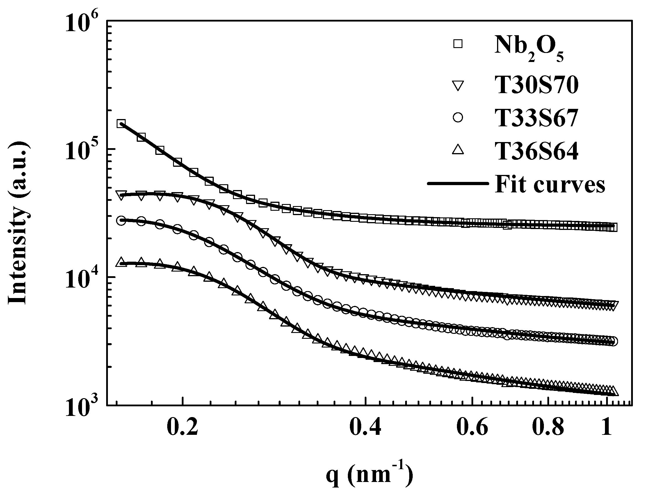
Figure 1. Optimized refractive indices of the bottom layer nM and objective function f versus refractive indices of the middle layer nH. The refractive index of the top layer is set to be 1.44 and the central wavelength is 550 nm. The optical thicknesses of the triple-layer AR coating onto fused quartz are quarter-half-quarter.
Coatings 10 00737 g001
Figure 2. (a) Illustration of the experimental (symbols) and calculated (lines) transmittance spectra of film SiO2 and Nb2O5; (b) dispersion curves of refractive index and extinction coefficient obtained from transmittance data fits of the corresponding films.
Coatings 10 00737 g002
Figure 3. Experimental small-angle X-ray scattering (SAXS) profiles I(q) of the Nb2O5 and TiO2–SiO2 sols. The profiles are shifted vertically for clarity. The fit curves were obtained using the Beaucage model.
Coatings 10 00737 g003
Figure 4. FTIR spectra of TiO2–SiO2 hybrid film T33S67, SiO2 film and TiO2 film.
Coatings 10 00737 g004
Figure 5. TEM image of gel powder scraped from the film T33S67.
Coatings 10 00737 g005
Figure 6. (a) Representative fitting using the Cody–Lorentz model for film T33S67; (b) dispersion curves of refractive index and extinction coefficient of the TiO2–SiO2 hybrid films.
Coatings 10 00737 g006
Figure 7. Measured (symbols) and theoretical (line) transmittance spectra of the triple-layer broadband AR coating on both sides of fused quartz substrate. The inset schematic diagram lists the optimized film thickness for each layer of the antireflective (AR) coating. Labels M, H and L for individual layers are from the subscripts for film refractive indices in Equations (1) and (2).
Coatings 10 00737 g007
Figure 8. AFM images of (a) bottom layer T33S67, (b) middle layer Nb2O5, (c) top layer SiO2 and (d) triple-layer AR coating.
Coatings 10 00737 g008
Figure 9. Experimental transmittance spectra of λ/2-λ/4 (S|2HL|A) and λ/4-λ/4 (S|ML|A) double-layer AR coatings. The layers M, H and L are T33S67, Nb2O5 and SiO2, respectively. Both the two AR coatings were prepared via the dip-coating method.
Coatings 10 00737 g009
Figure 10. Durability tests of the triple-layer AR coatings. (a) Microscope photograph of coating surface after rubbing with a 3H pencil; (b) corresponding Transmittance spectra of the AR coating shown in (a); (c) change in transmittance of the AR coating before and after surface modification by HMDS. Insets are the corresponding water contact angle images. Transmittance spectra of the surface-modified coating placed in the normal air environment for one month and three months are also shown.
Coatings 10 00737 g010
Table 1. Structural parameters of the precursor solutions and optical properties of the corresponding films. Radii of gyration, Rgi and Porod’s exponents, Pi (for i = 1, 2), as obtained from the Beaucage model [44]. f denotes the objective function of the optimization process by selecting different TiO2–SiO2 hybrid films for the triple-layer AR coating.
Precursor SolutionRg1 [nm]P1Rg2 [nm]P2n550k450f
Nb2O515.82.682.0722.95 × 10−7
T30S7013.03.359.21.221.5844.20 × 10−50.01107
T33S6716.13.007.91.251.6331.69 × 10−50.01090
T36S6412.82.919.61.461.6462.00 × 10−50.01094

