Interaction of Strontium Zirconate Plasma Sprayed Coating with Natural Silicate (CMAS) Dust—Origin of Luminescent Phases


Institute of Plasma Physics, ASCR, Za Slovankou 3, 182 00 Prague 8, Czech Republic
Coatings 2020, 10(8), 738; https://doi.org/10.3390/coatings10080738
Submission received: 25 June 2020
/
Revised: 22 July 2020
/
Accepted: 25 July 2020
/
Published: 28 July 2020
(This article belongs to the Special Issue Science and Technology of Thermal Barrier Coatings)
Abstract
:Strontium zirconate (SrZrO3) commercial powder was plasma sprayed using a high-feedrate water-stabilized plasma system (WSP) torch. Coatings with a thickness of about 1 mm were produced. Now, we are concentrating on a topic never addressed for pure SrZrO3 coatings: how the coatings interact with natural dust, known as calcium-magnesium-aluminum-silicate (CMAS). We selected various regimes of thermal treatment where SrZrO3 coatings were exposed to CMAS, and studied chemical changes, phase changes and the microstructure evolution of the influenced coatings. Microhardness of the exposed coatings was monitored as well. The results would help to understand, how the excellent refractory material SrZrO3 interacts with natural silicates. We kept in mind that pure SrZrO3 is not optimal for a thermal barrier application because of high-temperature phase transformations, but to study the CMAS-induced phenomena in more complex compositions, for example La2Zr2O7-SrZrO3, is difficult and interpretations have not been completed currently. The value of the actual research is in the separation of the phenomena typical just for SrZrO3. A potential for newly developed phases to serve as a sacrificial components of various barrier-coating systems is discussed. Several physical aspects of the newly developed components are discussed as well, namely the luminescence. Here the dust-based phases shifted down the temperature at which luminescence can occur in pure SrZrO3 ceramics. The entire thickness of influenced layers was relatively high, around 300 µm. The amorphous component, predominant after short-term CMAS exposure, was subsequently crystallized to various phases, namely SrSiO3 and monoclinic as well as tetragonal zirconia.
1. Introduction
To improve their efficiency and design, turbine engines use ceramic-coated components. These coatings, known as Thermal Barrier Coatings (TBC), are designed for use at high temperatures [1,2,3,4,5,6]. TBCs serve as a protection for the base metal and super-alloy components by preventing them from experiencing high-temperature degradation [2]. They also increase the efficiency and lifetime of the components, besides providing creep resistance, thermal shock resistance, strain tolerance, higher temperature stability with respect to the substrate material and protection against hot corrosion [1,2,3,4]. Reducing the temperature of the metal is one objective of the top ceramic TBC. A state-of-the-art TBC is yttria-stabilized zirconia (YSZ) composed of ZrO2 with 6%–8% Y2O3 [3,4,5]. The microscopic structure of TBC is always very inhomogeneous [6].
Atmospheric plasma spray (APS) is used for depositing ceramic TBC [6]. So called “splats” are created by the plasma spray as flattened particles. Due to its quick solidification, the sprayed powder produces a coating on a clean surface of a substrate. An incomplete bonding between splats caused by the relaxation of residual stresses when the splat is being cooled, or by trapped gases, and also lack of adhesion, are typical APS–TBC drawbacks [6,7]. The structure of the porous TBC, which contains cracks, pores, crack/coating interfaces, pore/coating interfaces and layer interfaces, affects its effective thermal conductivity [1,2,6,7].
In the case of sprayed TBC, the microstructural defects consist of three types of pores: interlamellar pores—that result from the build-up of micro-splats; microcracks—that result from the stress relief after coating deposition; and globular pores—that are due to a lack of complete filling. These three types of pores fall into different ranges of size distribution. It has been shown that the thermal conductivity is strongly dependent on the pore morphology and porosity [8,9]. Optimum porosity level in TBC is considered to be about 15% total porosity as a compromise between positive function of porosity to minimize thermal conductivity and negative function of worsening the coating integrity and mechanical properties. Some 20% to 25% of the total porosity is formed by cracks [9].
Among the investigated ceramic TBC candidates, SrZrO3 with perovskite structure has a high melting point, low thermal conductivity as well as the possibility of extensive substitution of ions at the A or/and B site, making it a promising TBC candidate material [7,10]. Application of pure SrZrO3 for the TBC seems to be limited because of its high-temperature phase transformations [10]. SrZrO3 exhibits a pseudo-tetragonal structure at 750 °C and a tetragonal structure at temperatures higher than 840 °C. The pseudo-tetragonal structure creates a lattice mismatch between Sr-O atoms, so that coating delaminates easily [11]. Delamination at the boundary bond-coat/top-coat is the most frequent case [2,5]. Elsewhere [12], the transformation sequence at heating is described as follows: orthorhombic (Pnma)→730 °C→pseudo-tetragonal (Imma, c/a < 1)→860 °C→tetragonal phase (I4/mcm, c/a > 1)→1170 °C→cubic (Pm3m).
When the gas turbine operates in a severe environment, such as the desert or the vicinity of a volcanic eruption, siliceous mineral debris matters (dust, sand and ash) in air are ingested by the turbine and deposited on the hot TBC surfaces as molten calcium–magnesium–alumino-silicate (CMAS) [13]. Immediately when CMAS melting takes place, it infiltrates into the TBC material via open porosities in APS deposited TBC and undergoes a series of chemical reactions with the TBC-forming oxides [14]. Upon cooling, CMAS solidifies and develops a high stress level because the pores were blocked. In conventional TBC, YSZ partially dissolves in the CMAS, causing disruptive phase transformation (from tetragonal ZrO2 to monoclinic ZrO2) accompanied with a significant volume increase (up to 5%) [15,16]. The size of CMAS particles could be from a nanometer range up to approximately half a millimeter. Kakuda et al. [17] investigated the effect of amorphous CMAS infiltration on the thermal properties and heat transport of plasma-sprayed (APS) coatings and observed a rise in both volumetric heat capacity and thermal conductivity of the coating upon infiltration. Concerning the mechanical attack of the dust on TBC, cavitation is mentioned [18], but the chemical attack is considered as more serious.
A paper dealing with an interaction of CMAS and the La2Zr2O7-SrZrO3 composite TBC coating [19] expressed a challenge that the interaction behavior of SrZrO3 in contact with CMAS melt at high temperatures requires further investigations in the future. This challenge to elaborate such experiments is now accepted by a co-author of papers dealing with multifunctional SrZrO3 coatings [20,21,22]—and this is in a focus of the actual paper. Keeping in mind that pure SrZrO3 is not optimal for a thermal barrier application because of high-temperature phase transformations but to study it directly in a composite with other refractories, for example La2Zr2O7-SrZrO3, is difficult [19], the decision was to study it as a single-component coating material. This is the main novelty of the current paper.
2. Materials and Methods
2.1. Sample Preparation
Plasma spray grade strontium zirconate powder supplied by Cerac Incorporated (Milwaukee, WI, USA) was used as the feedstock. The powder size was 74–150 µm. Plasma spraying was done by the water-stabilized plasma system (WSP) torch [23] at 150 kW power (500 A, 300 V). The feeding distance (from the plasma exit nozzle to the point of the powder feeding in the plasma stream) was 80 mm and spray distance (from the plasma exit nozzle to the substrate) was 350 mm. Compressed air was used as the feeding gas and the substrates were preheated to 460 °C. This high temperature was selected with the purpose to minimize the cooling rate for impacting splats. Preheating was done by plasma torch passes with the powder feeding switched off. After each pass of the torch, manipulated by a robotic arm, the temperature rose to 350 °C and was pushed down to 170 °C by a compressed air flux before the next pass started [20].
Reactivity of the SrZrO3 coating with calcium—magnesium—aluminum-silicate (CMAS) powder was tested. The CMAS powder was Ultrafine Test Dust “Arizona desert sand” produced by Powder Technology (Arden Hills, MN, USA). Its chemical composition provided by the producer is SiO2 (50%, semi-quantitative content), Na(AlSi3O8) albite (32), CaMg(Si2O6) diopside (16), CaCO3 (2). The size of CMAS particles was in single micrometers. The dust powder with a concentration of 30 mg·cm−2 [19] was mixed with ethanol and the resulting slurry was applied on the coating surface by a brush. Then, this sample was dried in air at room temperature for 3 h and subsequently annealed in air (laboratory furnace Clasic, Řevnice, Czech Republic) using dwell times of 1, 4, 8 and 10 h, respectively, at 1250 °C. Heating ramp was 8 °C·min−1 and cooling ramp 6 °C·min−1. At this temperature (and during this time) the CMAS melt interacts with the coating, i.e., it both infiltrates into the coating and reacts with it. To better understand the phase constituents of the reaction products, the CMAS powder was mixed with the SrZrO3 feedstock powder with a weight ratio of 1:1 [19] by mechanical blending, followed by heat treatment with 10 h dwell time under the same conditions as the TBC specimens.
2.2. Characterization
2.2.1. Phase Composition
Samples of the feedstock powder and sprayed coatings were analyzed by the X-ray diffraction technique. Diffraction patterns were collected with the PANalytical X’Pert PRO diffractometer (Malvern PANalytical, Almelo, The Netherlands) equipped with a conventional X-ray tube (Cu-Kα radiation, 40 kV, 30 mA) and a linear position sensitive detector PIXcel with an anti-scatter shield. A programmable divergence slit set to a fixed value of 0.5°, Soller slit of 0.04 rad and mask of 15 mm were used in the primary beam. A programmable anti-scatter slit set to fixed value of 0.5°, Soller slit of 0.04 rad and Ni beta-filter were used in the diffracted beam. Data were collected in the range of 10°–120° 2θ with the step of 0.013° and 300 s/step producing a scan of about 2 h 48 min.
Qualitative analysis was performed with the HighScorePlus software package (Malvern PANalytical, Almelo, The Netherlands, version 4.9.0) and the PDF-4+ database. Diffrac-Plus Topas software package (Bruker AXS, Karlsruhe, Germany, version 4.2) was used for estimating the Degree of Crystallinity (DoC). Structural models of all identified phases were taken from the PDF-4+ database.
2.2.2. Microstructure
Scanning electron microscopy (SEM) observation was done using the Phenom-Pro microscope (Thermo Fisher Sci., Eindhoven, The Netherlands) equipped by the CeB6 thermionic cathode and working in backscattered electron (BSE) mode. The images were collected at 10 kV electron beam tension. Energy Dispersive X-ray (EDX) analysis, which is a part of the SEM, was used to determine the elemental composition of a sample. Each element emits characteristic X-rays as an interaction between the sample and a focused electron beam. Consequently, the EDX spectrum is evaluated, and based on a unique set of peaks for each element, the composition of the sample is determined. The X-ray signal used for EDX-measurements comes from an area that is at least 1 µm in diameter and around 1.5 µm depth. The element EDX maps were collected at 15 kV electron beam tension.
Polished cross sections of the coatings were prepared for microscopic observation and for microhardness measurement. Light micrographs as a base for image analysis of porosity were taken at 250x magnification via CCD camera EOS 500D (Canon, Tokyo, Japan) attached on the microscope Neophot 32 (Zeiss, Oberkochen, Germany) and processed with the software Lucia (4.62, Laboratory Imaging, Praha, Czech Republic). For a more complex description of pores, additional criteria besides the porosity percentage (area fraction of voids, i.e., pores and cracks, in the TBC material) were introduced. “Number of Voids per unit area” (N.V.) of the cross section in combination with the porosity percentage could distinguish between porosity composed from a large number of fine voids or from a low number of coarse voids. “Equivalent Diameter” (E.D.) of voids represents their size distribution. Circularity could have values between 1 (i.e., a circle representing a globular pore) and 0 (i.e., a line representing a flat pore or a crack). All parameters were calculated for 3 images of each sample.
Selection of samples for microstructure study was done carefully to represent central parts of the planar TBC coating far enough from the edges. Polished cross-sections were prepared from as-deposited samples. Cutting was done using a diamond blade, subsequently the sections were mounted in a resin, and polishing was carried out using the Tegramin-25 automatic system (Struers, Denmark).
2.2.3. Microhardness
Vickers microhardness was measured on polished TBC sections by optical microscope Neophot 2 (Zeiss, Oberkochen, Germany) equipped with a Hanemann head and Vickers indenter using 1 N load. The mean value of microhardness was calculated as an average from 20 indentations.
3. Results and Discussion
3.1. Microstructure and Porosity
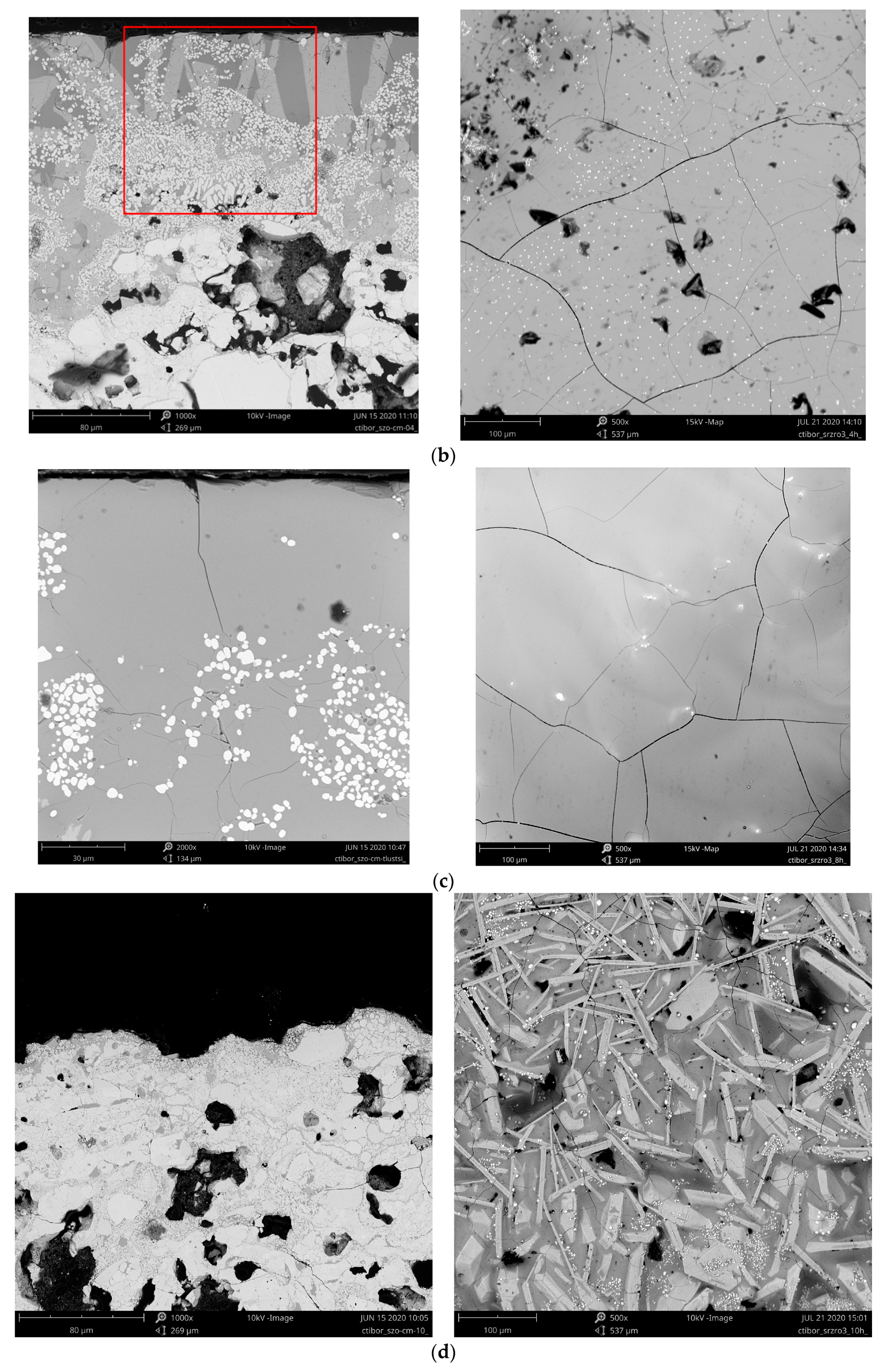
After 1 h a CMAS residuum clearly covers the coating, Figure 1a. Some fine globular particles, however, developed deeper in the coating. The rod-shaped particles and globular particles have developed after 4 h in the interaction layer (Figure 1b), which looks, however, dense and not porous as in the literature [19]. Since the porosity in the coating was discontinuous and irregular, the infiltration was, expectably, inhomogeneous. After 4 h, Figure 1b, the fine globular particles are developed within the entire thickness of the residual CMAS and are visible also on the surface. After 8 h, Figure 1c, they disappear again. The cracks’ character on the surface after 4 h and also 8 h correspond to the glassy character of the residual CMAS. After 10 h, Figure 1d, a significant whisker-like crystallization appears, whereas the matrix between the elongated faceted particles looks again glassy. Moreover, some fine globular particles appear again, and porosity is now opened to the surface (like in as-sprayed SrZrO3).
The thickness of the influenced layer increased from 222 µm after 1 h CMAS attack to 333 µm after 8 h. Cai et al. [19] reported only 11 µm after 1 h and 102 µm after 12 h for La2Zr2O7-SrZrO3 composite coating, although the annealing schedule was very similar to our case.
Berker et al. [14] reported 30 µm influenced depth after 3 h at 1300 °C for Yb-doped SrZrO3 coating. In these comparisons the initial growth of the influenced layer in our SrZrO3 coatings looks rather large. This was, first of all, because of the high porosity of the as-sprayed coating and due to this fact by easy proliferation of CMAS into the deeper layers of the coating. In contrast, after CMAS attack the coating surface became rather smooth and dense. Sometimes the published experiments were done with a lower concentration of CMAS per unit area of the coating, e.g., 10 mg·cm−2 [24]. In such a case, any CMAS residuum is formed on the top of the coating and—just in the beginning—the whole amount of CMAS is consumed for the interaction. Which approach is more realistic, from the application standpoint, is doubtful.
Evolution of porosity parameters, Table 1, indicates a general trend to the coarsening of porosity (pores coagulation) becoming more globular. Porosity area fraction increased and number of voids per mm2 decreased (i.e., fewer but larger pores), equivalent diameter increased and circularity as well. However, these general trends are affected with certain oscillations—i.e., highest porosity and largest pores after 4 h. Porosity of the SrZrO3 as-sprayed coating was rather high, 23.8%, and after 1 h at 1250 °C it shifted upwards, 26.6%. After 4 h dwell time was it even higher, 32.1%. After 8 h dwell time approached again approximately the as-sprayed level, 25.1%. After 10 h was it even higher, 27.7%. Such oscillations could also be viewed as a sacrificial layer development and “ingestion”. Repeatedly, a contiguous layer is formed on the surface, sealing the open porosity, but the total porosity is not influenced. The character of CMAS is too aggressive to serve as a simple liquid sintering aid for the base coating. Furthermore, in case of TBC application of SrZrO3, CMAS not only decreases the strain tolerance [2] of the coating but also left the surface opened for the possible next CMAS attack even after 10 h. Observation of microstructures indicates a “transitive” character of the sample after 4 h. Some CMAS remains always on the SrZrO3 coating surface after CMAS attack at 1250 °C, resulting in the difficulty to identify all the reaction products (hidden below) by XRD.
Coagulation of pores manifested itself by the increase of E.D. (as-sprayed–8.94 µm; 1 h–9.36 µm; 10 h–9.53 µm) and decrease of no. of pores per square millimeter (as-sprayed–5771; 1 h–4341; 10 h–4957). Circularity of pores correspondingly increased, indicating round shape of pores, physically favored after long-term annealing (as-sprayed–0.511; 1 h–0.695; 10 h–0.760), Table 1.
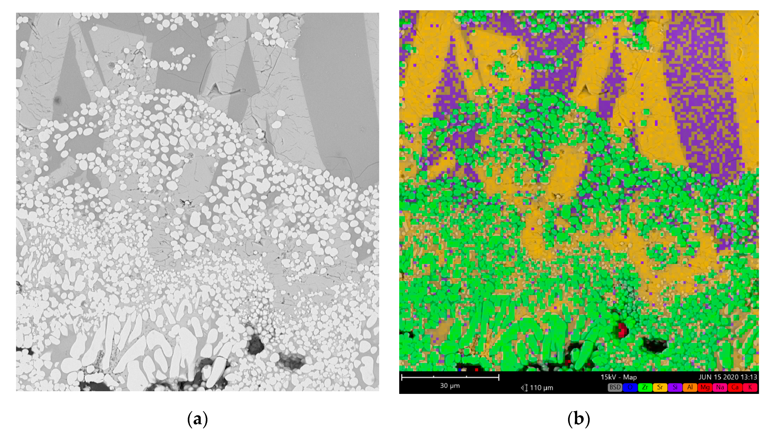
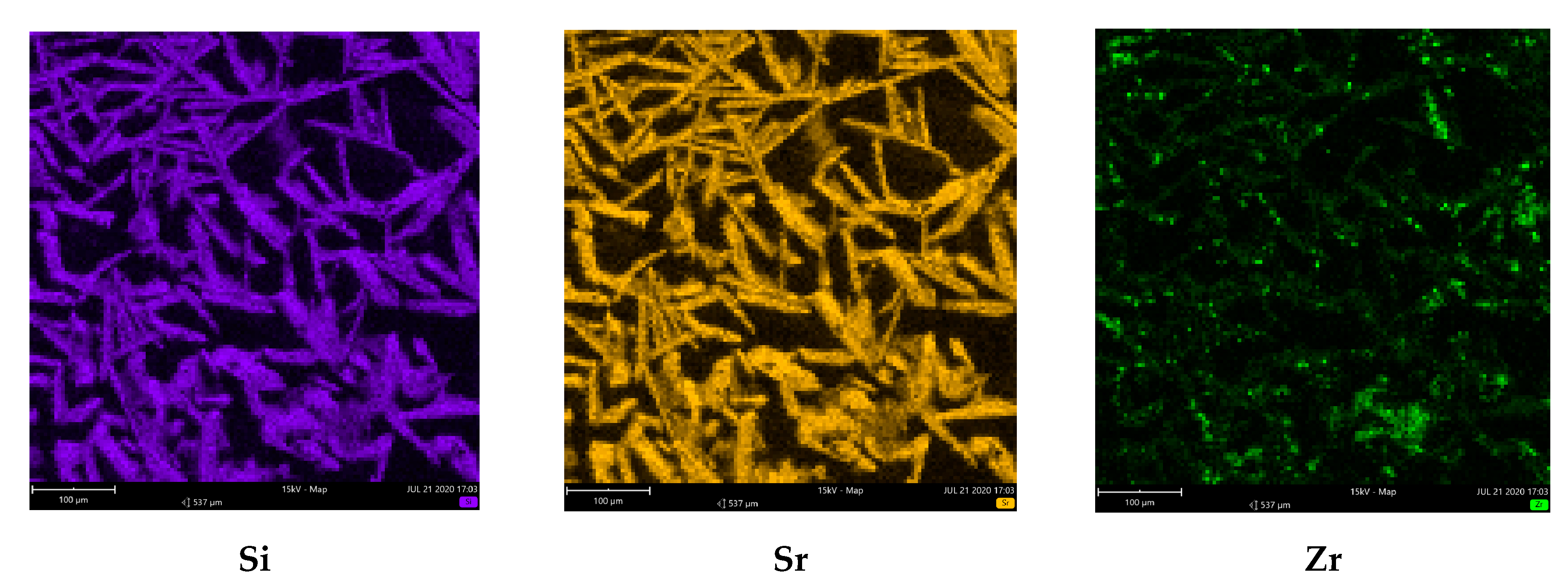
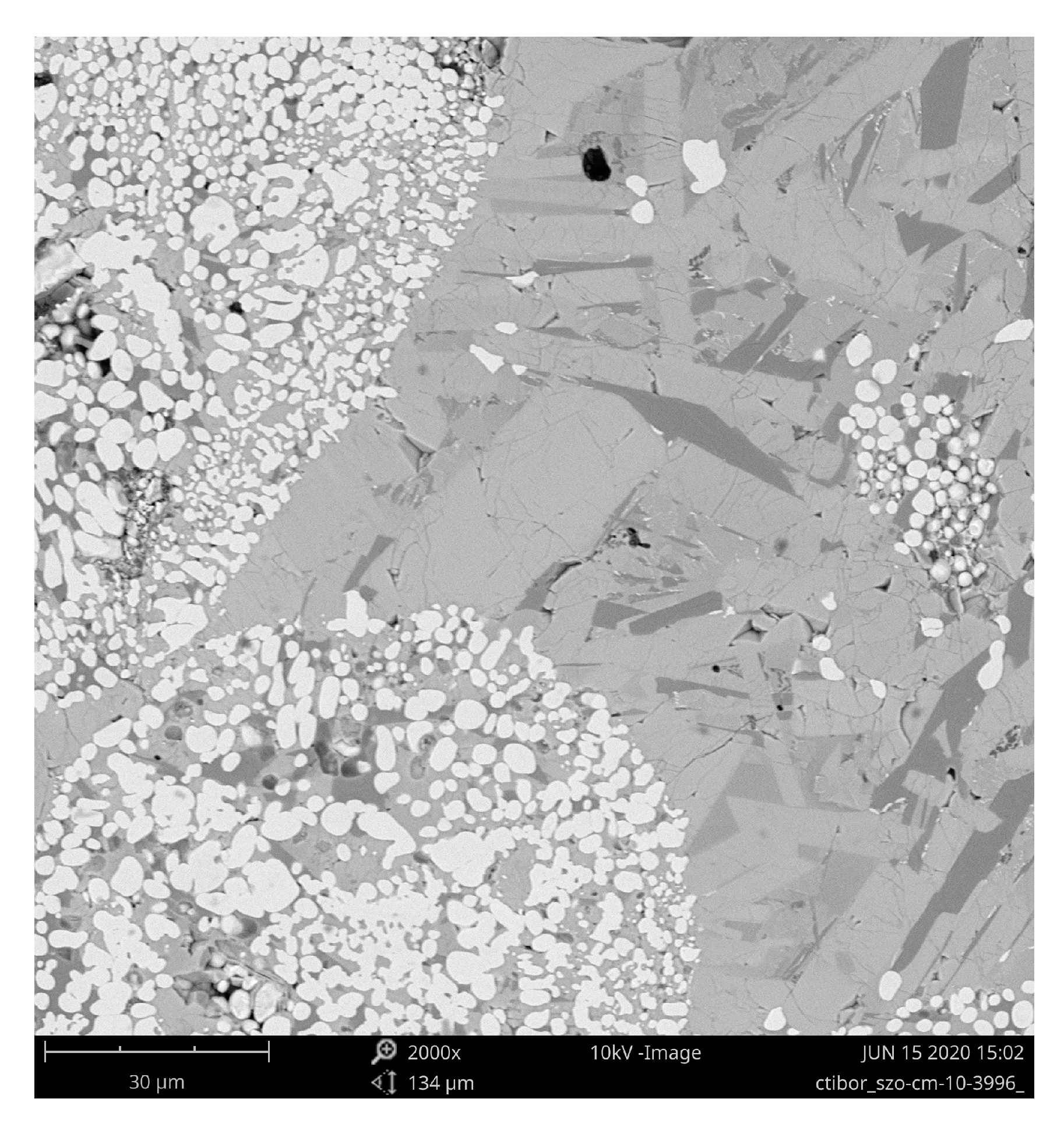
Figure 1 shows that some globular particles disperse in the CMAS melt after 4 h, whereas earlier they were present only in the depth of about 50 µm. Moreover, distinct columnar-like areas with different grey levels developed in the CMAS melt, see in larger details in Figure 2a. Figure 2b shows that, based on the EDX measurement, darker columns are Al-rich, lighter columns are Sr-rich and the fine globular particles as well as rod-shaped fine particles (both white) are Zr-rich. At the beginning (1 h) a Si-rich amorphous superficial layer based on molten CMAS is formed, Figure 1a, with traces of monoclinic ZrO2, crystalline SrSiO3 and two forms of SiO2, i.e. cristobalite and quartz, Table 2. After 4 h, Al-rich (probably spinel MgAl2O4) columns are combined with the earlier developed features, but an amorphous content is still predominant. Interestingly, the Al-rich columns are free of the fine cracks present in the neighboring Sr-rich columns, Figure 2a. After 8 h the globular Zr-rich particles “sunk” deeper down to the “glassy matrix”, Figure 1c. The content of amorphous material decreased as the reaction time increased from 1 to 10 h, see below XRD-based results. The Al-rich and Si-rich columns and globular Zr-rich particles are interpenetrated by residual CMAS melt, Figure 1d. SrZrO3 seems to decompose to SrO and ZrO2. Sr is depleted in the interaction zone, dissolving into the glass while ZrO2 precipitated. After 10 h the surface looks recrystallized, Figure 1d. It contains white globular Zr-rich particles, but the main feature is whisker-like crystals that correspond roughly to SrSiO3 phase, Figure 3. The resting “matrix” is most probably amorphous, since according to EDX it contains besides Si, Sr and Zr also between 1% and 2% of each: Al, Mg, Na and Ca.
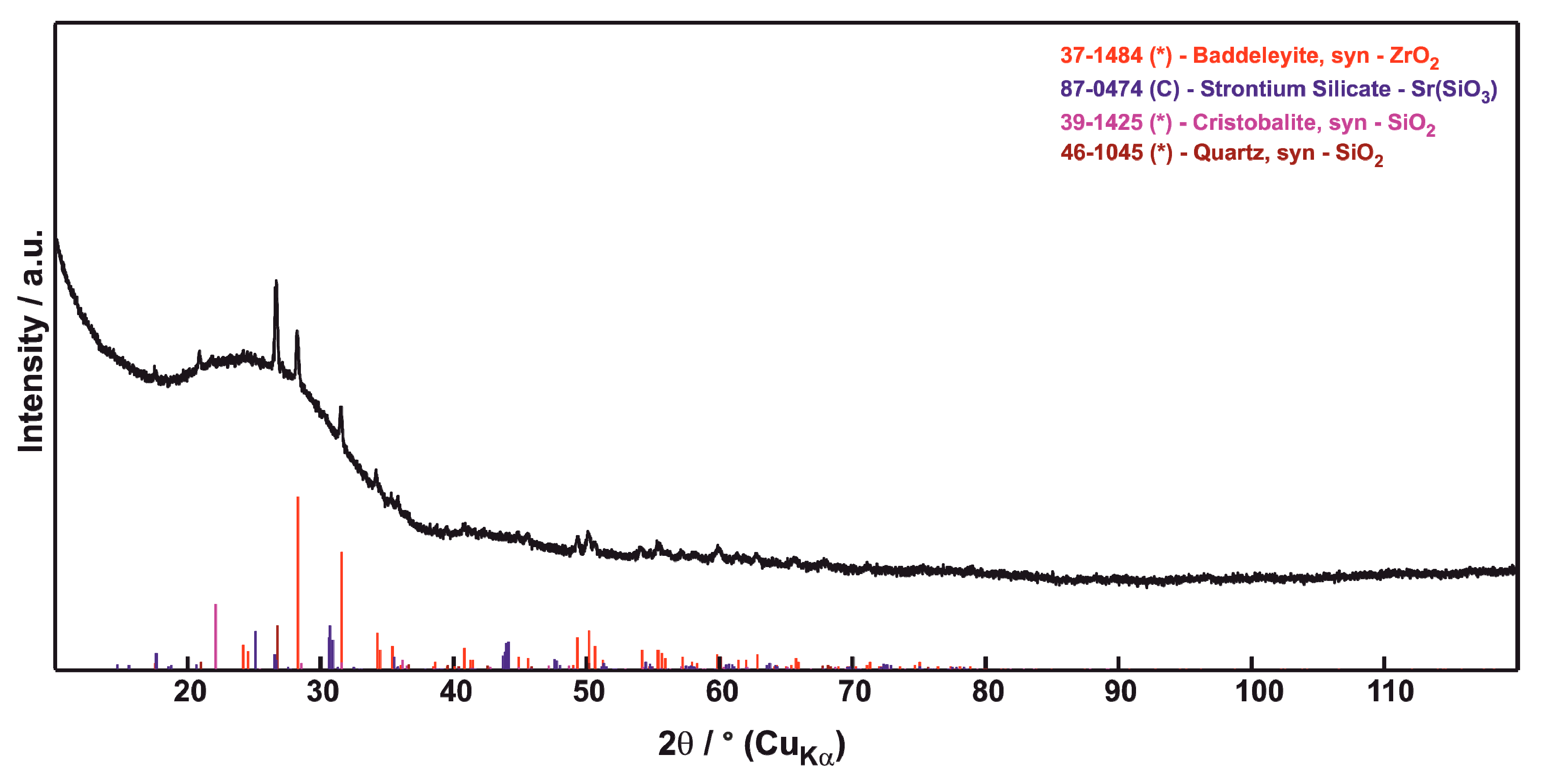
3.2. Phase Composition
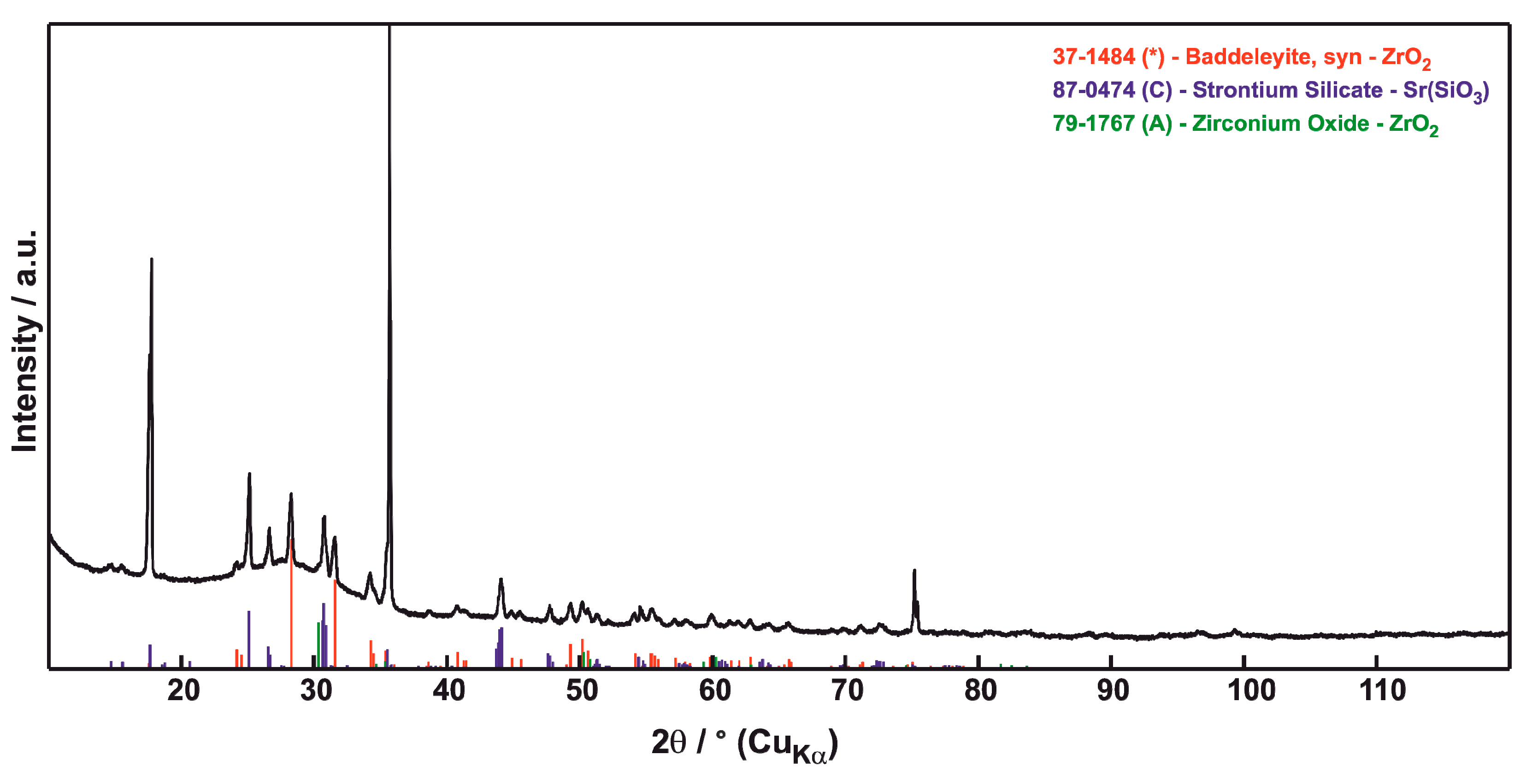
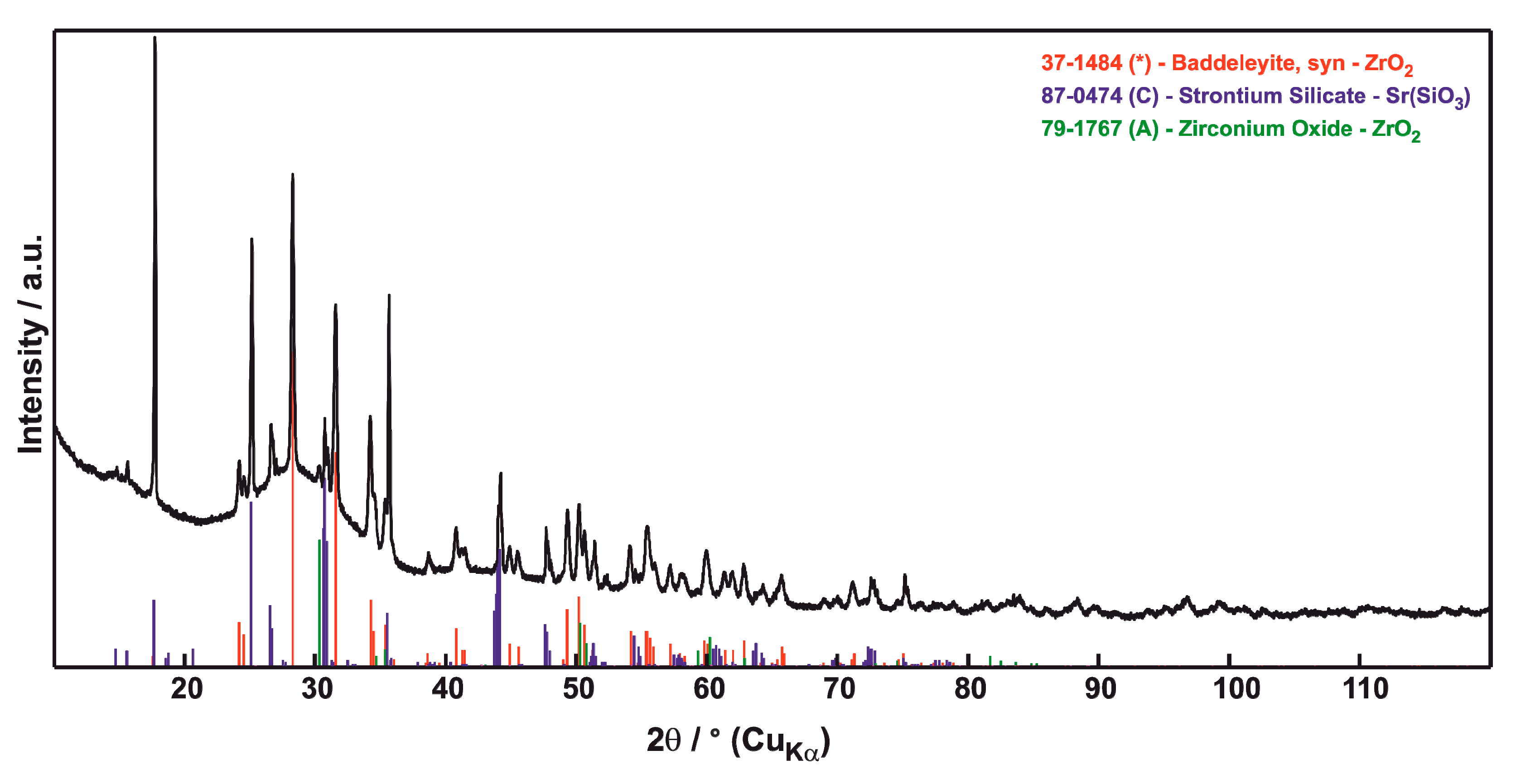
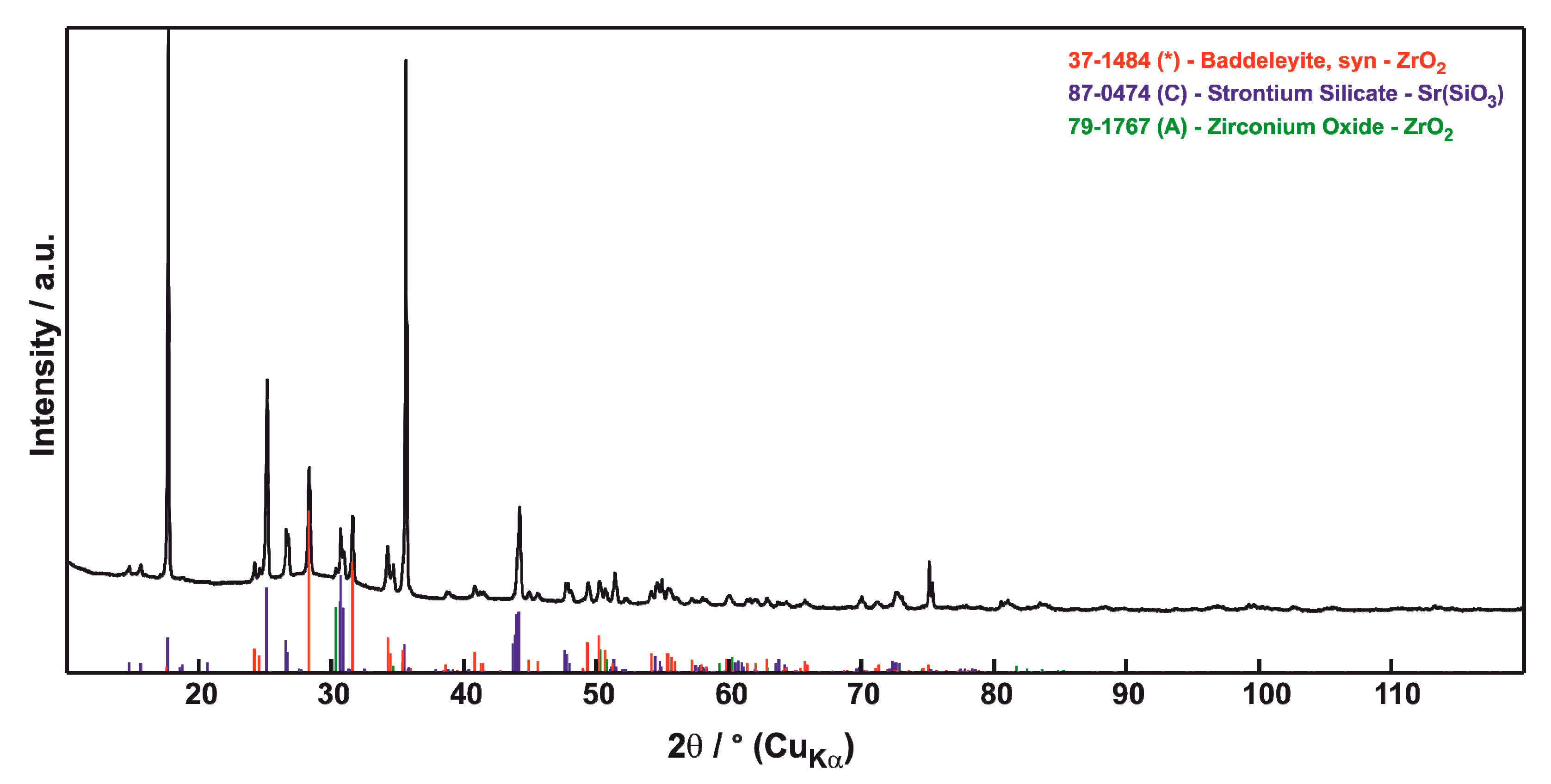
X-ray diffraction (XRD) results are summarized in Table 2. ZrO2 in both—monoclinic “baddeleyite” P21/c and tetragonal P42/nmc—forms has been found in the irradiated volume. After 1 h, Figure 4, the surface is practically totally amorphous with only few percent of crystalline phases—SrSiO3, SiO2 and ZrO2 monoclinic. This material is CMAS-based glass. Because of its composition, CMAS behaves as a glass, i.e., the heating/cooling sequence in the furnace is although too fast for its crystallization. After 4 h annealing, Figure 5, SrSiO3 (20%), ZrO2 monoclinic (12%) and ZrO2 tetragonal (4%) were detected. ZrO2 monoclinic started to be the main component after 8 h (content 28%), Figure 6. SrSiO3 content dropped (16%) and ZrO2 tetragonal did as well (2%). After 10 h, Figure 7, SrSiO3 was again the most important constituent (42%), whereas ZrO2 monoclinic content dropped (21%) and tetragonal did as well. Always, the rest of the material was amorphous, with the content progressively decreasing with the annealing time (the intensity of peaks increased with time), but being until 8 h higher than 50 percent. XRD results deal only with surface of the samples. Amorphization of the originally crystalline coating is, however, the main aspect of the interaction with CMAS.
Based on reported [25] thermal analysis results, the temperature of the orthorhombic-to-tetragonal phase change has a value of 848 °C for SrZrO3. A local minimum of weight gain [25] was recorded by us for the same temperature. Concerning the main phase changes the predominant phenomenon is an inverse run of the reaction described in literature [26] on samples left at 1073 °C for one hour.
SrSiO3 + ZrO2 = SrZrO3 + SiO2
In our case the process proceeds as:
SrZrO3 + SiO2 = SrSiO3 + ZrO2
ZrO2 tetragonal (a “frozen” high-temperature phase) from the TBC coating transformed to ZrO2 monoclinic under 1170 °C due to slow cooling in the furnace.
We suggest that the content (13 percent) of tetragonal ZrO2 from the as-sprayed coating was converted at the presence of CMAS to monoclinic ZrO2, whereas the new tetragonal ZrO2 was transformed from SrZrO3 by its decomposition via chemical reaction (Equation (2)). When SrZrO3 will be decomposed to 50 molar percent of SrO and 50 molar percent of ZrO2, the 50 molar percent of SrO could react with SiO2 completely to SrSiO3 [27].
To identify the reaction products between the CMAS and the SrZrO3 coating, a mixture of the CMAS powder as the solvent and the SrZrO3 feedstock powder as the solute (weight ratio: 1:1) was homogeneously mechanically blended and then heat-treated at 1250 °C for 10 h. Besides monoclinic and tetragonal ZrO2, a Na4Ca4(Si6O18) combeite phase appeared. SrZrO3 in the La2Zr2O7-SrZrO3 composite coating [19] reacted much less intensively with CMAS compared to La2Zr2O7. Absence of CMAS-induced through-thickness cracks in our samples could be ascertained mainly to the identical thermal expansion of SrZrO3 [19] and SrSiO3 [28], 10.9 × 10⁻⁶ K−1.
Concerning the “oscillations” in the character of the influenced layer(s) we conclude that the amorphous materials formed preferably on the surface from CMAS crystallizes preferably “from the bottom”, i.e., in interaction with the coating. The crystallization opens new pores (via dimensional shrinkage). New proportions of CMAS melt fits into these new pores and sinks deeper into the coating. This repeated process stops after 10 h where finally not enough residual CMAS on the surface exists.
From this standpoint SrZrO3 is not advantageous TBC material since the crystallization front seems to move slowly. Better CMAS blocking layers or sacrificial layers would form when the crystallization is as fast as possible. In this view La2Zr2O7 in the system La2Zr2O7-SrZrO3 [19] served as a “crystallization promoter” and SrZrO3 itself is well CMAS-resistant under ultra-short exposure but started to be CMAS-nonresistant after at least 1 h.
The most stable and most desired phase in the TBC structure among the newly developed phases is tetragonal ZrO2. It stems from SrZrO3 by its decomposition. However, amorphous material is always present in high amounts, and evidently monoclinic baddeleyite crystallizes preferably from the amorphous phase. Disadvantageous is also the fact that admixtures are preferably incorporated in the lattice of tetragonal ZrO2. Among them so called silica-substituted zirconia is rather stable [29]. However, in case of reacting with CMAS, rather Ca, Al or Na atoms would occupy the place of Si, since Si elements form in large quantities the SrSiO3 phase.
3.3. Mechanical Properties
We could summarize microhardness data from Table 3: The SrZrO3 coating was very similar to the as-sprayed samples with values between 5.6 and 6.1 GPa.
Effect of sintering was negligible in the base material since the annealing temperature was markedly below the sintering temperature of SrZrO3. The influenced superficial layers, visibly changed by interaction with CMAS, were similarly hard but the duration of annealing led to progressively decreased microhardness (GPa): (1 h–6.5; 4 h–5.9; 8 h–5.6; 10 h–5.5). The mixture of powders sintered in a crucible exhibited a very similar value to the coatings: 5.5 GPa. It contained globular (ZrO2-rich) particles and glassy matrix (CMAS-rich) that was in fact a “liquid-phase sintering” agent. In this arrangement, i.e., individual particles of SrZrO3 in contact with the CMAS melt, the interaction process is faster. Among the components the particles were harder, 6.0 GPa than the matrix, 5.0 GPa. SrZrO3 bulk ceramic microhardness was reported to increase after 100 h at 1450 °C to 5.5 GPa compared to 4.5 GPa for the as-sintered sample [30].
Combining microhardness with thickness and porosity evaluations we see: after 4 h the influenced layer is thinner and weaker than after 1 h. After 8 h the influenced layer is even less hard but thick and less porous—with the lowest porosity and smallest pore size. The influenced layer is again thinner and maintained its hardness but the coating itself is harder due to pore sealing.
3.4. Optical Properties
The scattering coefficient of SrZrO3 is reported to be higher than that of YSZ, which is beneficial for the TBC application because most of the incident radiation will be reflected back to the hot gas stream instead of being absorbed by the coating or penetrating the coating leading to the increase of temperature on the base superalloy [31].
In plasma-sprayed TBCs, the scattering is mainly due to the refractive index mismatch between the ceramic coating material and the interior of TBC pores and cracks. This was proved by the decrease of scattering/reflectance (or increase of transmittance) through infiltrating TBC with epoxy or CMAS, whose refractive index is close to the coating material [32]. The decrease of the scattering coefficient with the increase of the wavelength is due to the decrease of the relative size of the scattering centers (internal pores and cracks) compared with the wavelength [33].
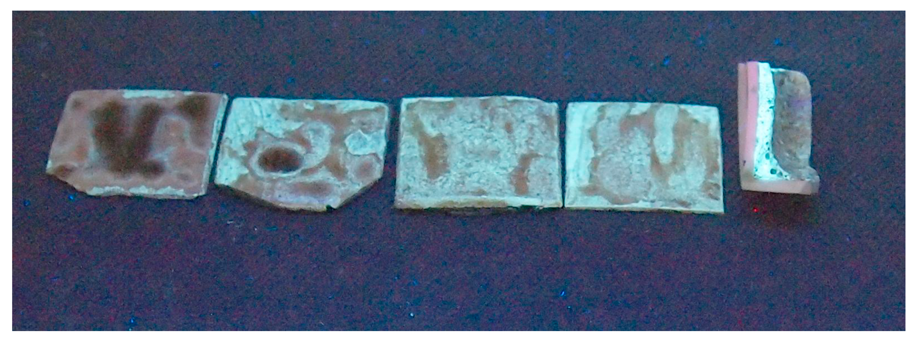
The brown-green color of the CMAS “glaze” is subsequently, with increasing annealing time, turned towards the yellow color typical for SrZrO3 powder and as-sprayed coatings. That is because the residual CMAS is consumed for the reaction, as described above. The yellow reflection as a response on a deep-violet illumination is called luminescence. The sintered mixed powder sample was more luminescent than the coating surfaces, Figure 8. The longer the dwell time, the lower CMAS amount directly at the surface and the highest the luminescence of the “coating itself”. The highest luminescence is seen for the sintered mixture of powders. Here, CMAS transformed into a “brown-green glaze”, surrounding fine yellow particles of the initial SrZrO3, serving partly as a “liquid-phase sintering” agent, and by this way decreasing the sintering temperature. The appearance, Figure 9, is more or less like a two-component composite with “intact” particles embedded in a fully remelted matrix. In fact, the particles are not intact—Sr from SrZrO3 is transferred to the matrix and the fine white globular particles should be ZrO2 (based on XRD and EDX).
Combeite, a component detected by XRD in the sintered mixed powders and having composition Na6Ca3(Si6O18), was reported to exhibit luminescence centered at about 615 nm [34]. SrZrO3 plasma sprayed coating was luminescent only after annealing in air at 1350 °C for 2 h [22]. SrZrO3 is good radiation energy absorber for energies above 3.8 eV [35]. Presence of SrSiO3 (in coatings) and combeite (in mixed powders) shifted the necessary annealing temperature for obtaining luminescent behavior down to 1250 °C. SrSiO3 with band gap energy 4.60 eV (higher than SrZrO3 with value this between 3.37 and 4.53 eV [35]) is itself less efficient luminescence material than SrZrO3 but could be formed with a much lower thermal load.
Similarly to the coatings, Figure 2, the sintered mixture of powders, Figure 9, contained globular Zr-rich particles with sizes under 10 µm. They originated evidently from SrZrO3, since the big “ball” in the left-bottom quadrant of Figure 9 is a particle of the spray feedstock powder (with diameter about 80 µm). The dark grey and pale grey “matrix” is evidently CMAS-based and similarly to coatings could be divided into a crack-free Si-rich darker component and cracked Sr-rich lighter component. Let us see that the Sr-rich component much more frequently surrounds the spray feedstock big “balls” that is coincident with the assumption of the Sr-depletion. Here, contrary to the coatings, Al concentration in such a matrix was always low, under 3 atomic percent. MgAl2O4 spinel seems to be absent in the sintered mixture of powders.
In general, to tailor the spraying of a TBC to the “optimum porosity” of about 15% (or having it even higher as in the present case) and in the same way make the TBC well resistant to the penetration of molten CMAS, is a problem. A way is to close the superficial porosity as much as possible. Thin barrier layer formed by e.g., laser remelting [36,37] of few superficial micrometers of as-produced TBC would be helpful. However, this additional step makes the production of TBCs even more expensive. Our strontium zirconate, initially even more porous, is on the beginning of interactions with CMAS rather resistant, due to the glassy character of CMAS, but after disappearing the residual CMAS from the surface is the coating surface again porous. However, the dangerous through-thickness cracks were not induced by CMAS within the microstructure of the coating.
Luminescence could be, in principle, used in the diagnostics of the TBC at room temperature. Let us imagine the SrZrO3-covered functional parts of a turbine. The turbine was in service subjected to CMAS attack. After cooling down at the maintenance interruption of the service, change (i.e., the increase) in luminescence would clearly signalize the reaction of the TBC with CMAS. Such a check would be fast and inexpensive. If the turbine was in service, but evidently not subjected to CMAS attack, the luminescence would help at diagnostics of the maximum service temperature—since pure SrZrO3 started to be luminescent after heat exposure at 1350 °C [22]. Of course, in case of more complex TBCs, like La2Zr2O7-SrZrO3, these aspects would be less clear, and this is one interesting avenue for future research to explore.
4. Conclusions
Strontium zirconate SrZrO3 was sprayed by a high feed-rate water-stabilized plasma torch, WSP, with a spray rate over 10 kg per hour to form a thick film. The as-sprayed coatings exhibited a lamellar microstructure and a relatively high porosity of over 23%. This thick film, considered as a thermal barrier coating (TBC), was now studied in interaction with natural silicate dust, so called CMAS, at 1250 °C. The crystalline as-sprayed coating was amorphized, whereas the resting crystalline proportion transformed to different phases than SrZrO3, namely monoclinic ZrO2 and SrSiO3. The proportion of these predominant phases varied with time of annealing (i.e., CMAS attack), whereas the general trend to crystallization of the amorphous content with longer dwell time was shown by XRD. The whole thickness of the influenced layer was as large as up to 333 µm. This is a typical thickness of the whole TBC coating in many industrial applications. SEM and EDX observation of the cross sections showed, also, an Al-rich component. The cracks’ formation selectively in the Sr-rich component and absence in the Al-rich component were observed as one of the results of CMAS attack, whereas the most dangerous through-thickness cracks were absent. A sintered mixture of powders (CMAS plus SrZrO3 spray feedstock) demonstrated the appearance of the most “exotic” phase-Na4Ca4(Si6O18) combeite. This component is luminescent, as was shown in our work, whereas contribution of SrSiO3 to the luminescence of the sintered mixture is also highly probable. Due to SrSiO3 presence, the coatings after interaction with CMAS are also partly luminescent. We suggest using the luminescence as a fast and cheap diagnostic technique of CMAS presence/absence in the structure of a potential SrZrO3-based TBC.
Author Contributions
Conceptualization, P.C.; methodology, P.C.; writing—original draft preparation, P.C.; writing—review and editing, P.C.; XRD and SEM analyses were arranged externally as barter services or paid services; other processing and analyses, P.C. All authors and collaborators have read and agreed to the published version of the manuscript.
Funding
This research received no external funding.
Acknowledgments
The author would like to thank to XRD (Petr Bezdička) and SEM (Petr Veselý) operators.
Conflicts of Interest
The author declares no conflict of interest.
References
- Padture, N.P.; Gell, M.; Jordan, E.H. Thermal Barrier Coatings for Gas-Turbine Engine Applications. Science 2002, 296, 280–298. [Google Scholar] [CrossRef]
- Evans, A.G.; Mumm, D.R.; Hutchinson, J.W.; Meier, G.H.; Pettit, F.S. Mechanisms Controlling, Durability of Thermal Barrier Coatings. Prog. Mater. Sci. 2001, 46, 505–532. [Google Scholar] [CrossRef]
- Levi, C.G. Emerging Materials and Processes for Thermal Barrier Systems. Curr. Opin. Solid State Mater. Sci. 2002, 8, 77–99. [Google Scholar] [CrossRef]
- Clarke, D.R.; Levi, C.G. Materials Design for the Next Generation Thermal Barrier Coatings. Annu. Rev. Mater. Sci. 2003, 33, 383–397. [Google Scholar] [CrossRef]
- Evans, A.G.; Clarke, D.R.; Levi, C.G. The Influence of Oxides on the Performance of Advanced Gas Turbines. J. Eur. Ceram. Soc. 2008, 28, 1405–1418. [Google Scholar] [CrossRef]
- Vassen, R.; Ophelia-Jarligo, M.; Steinke, T.; Emil-Mack, D.; Stöver, D. Overview on Advanced Thermal Barrier Coatings. Surf. Coat. Technol. 2010, 5, 938–949. [Google Scholar] [CrossRef]
- Clarke, D.R.; Philpot, S.R. Thermal Barrier Coating Materials. Mater. Today 2005, 8, 22–29. [Google Scholar] [CrossRef]
- Kulkarni, A.; Wang, Z.; Nakamura, T.; Sampath, S.; Goland, A.; Herman, H.; Allen, J.; Ilavsky, J.; Long, G.; Frahm, J.; et al. Comprehensive Microstructural Characterization and Predictive Property Modeling of Plasma-sprayed Zirconia Coatings. Acta Mater. 2003, 51, 2457–2475. [Google Scholar] [CrossRef]
- Wang, Z.; Kulkarni, A.; Deshpande, S.; Nakamura, T.; Herman, H. Effects of Pores and Interfaces on Effective Properties of Plasma Sprayed Zirconia Coatings. Acta Mater. 2003, 51, 5319–5334. [Google Scholar] [CrossRef]
- Cao, X.Q.; Vassen, R.; Jungen, W.; Schwartz, S.; Tietz, F.; Stöver, D. Thermal Stability of Lanthanum Zirconate Plasma-sprayed Coating. J. Am. Ceram. Soc. 2001, 84, 2086–2090. [Google Scholar] [CrossRef]
- Venkatesh, G.; Blessto, B.; Santhosh Kumar Rao, C.; Subramanian, R.; John Berchmans, L. Novel Perovskite Coating of Strontium Zirconate in Inconel Substrate. IOP Conf. Ser. Mater. Sci. Eng. 2018, 314, 012010. [Google Scholar] [CrossRef]
- Carlsson, L. High-temperature Phase Transitions in SrZrO3. Acta Crystallogr. 1967, 23, 901–905. [Google Scholar] [CrossRef]
- Li, W.; Zhao, H.; Zhong, X.; Wang, L.; Tao, S. Air Plasma-Sprayed Yttria and Yttria-Stabilized Zirconia Thermal Barrier Coatings Subjected to Calcium-Magnesium-Alumino-Silicate (CMAS). J. Thermal Spray Technol. 2014, 23, 975–983. [Google Scholar] [CrossRef]
- Berker Iyi, C.; Mecartney, M.; Mumm, D.R. On the CMAS Problem in Thermal Barrier Coatings: Benchmarking Thermochemical Resistance of Oxides Alternative to YSZ Through a Microscopic Standpoint. Uluslararasi Fen Arastirmalarinda Yenilikci Yaklasimlar Dergisi 2019, 3, 20–40. [Google Scholar]
- Kramer, S.; Yang, J.; Levi, C.G.; Johnson, C.A. Thermochemical Interaction of Thermal Barrier Coatings with Molten CaO-MgO-Al2O3-SiO2 (CMAS) Deposits. J. Am. Ceram. Soc. 2006, 89, 3167–3175. [Google Scholar] [CrossRef]
- Jing, W.; Hong-bo, G.; Yu-zhi, G.; Sheng-kai, G. Microstructure and Thermo-Physical Properties of Yttria Stabilized Zirconia Coatings with CMAS Deposits. J. Eur. Ceram. Soc. 2011, 31, 1881–1888. [Google Scholar]
- Kakuda, T.R.; Levi, C.G.; Bennett, T.D. The Thermal Behavior of CMAS-infiltrated Thermal Barrier Coatings. Surf. Coat. Technol. 2015, 272, 350–356. [Google Scholar] [CrossRef]
- Clarke, D.R.; Oechsner, M.; Padture, N.P. Thermal-barrier Coatings for More Efficient Gas-turbine Engines. MRS Bull. 2012, 37, 891–898. [Google Scholar] [CrossRef] [Green Version]
- Cai, L.; Ma, W.; Ma, B.; Guo, F.; Chen, W.; Dong, H.; Shuang, Y. Air Plasma-Sprayed La2Zr2O7-SrZrO3 Composite Thermal Barrier Coating Subjected to CaO-MgO-Al2O3-SiO2 (CMAS). J. Thermal Spray Technol. 2017, 26, 1076–1083. [Google Scholar] [CrossRef]
- Ctibor, P.; Nevrla, B.; Cizek, J.; Lukac, F. Strontium Zirconate TBC Sprayed by a High Feed-Rate Water-Stabilized Plasma Torch. J. Thermal Spray Technol. 2017, 26, 1804–1809. [Google Scholar] [CrossRef]
- Ctibor, P.; Sedlacek, J.; Janata, M. Dielectric Strontium Zirconate Sprayed by a Plasma Torch. Prog. Colol Colorants Coat. 2017, 10, 225–230. [Google Scholar]
- Ctibor, P. After-glow Luminescence of SrZrO3 Prepared by Plasma Spraying. Boletin Sociedad Espanola Ceramica Y Vidrio 2018, 57, 190–194. [Google Scholar] [CrossRef]
- Hrabovsky, M. Water-stabilized Plasma Generators. Pure Appl. Chem. 1998, 70, 1157–1162. [Google Scholar] [CrossRef] [Green Version]
- Mikulla, C.; Naraparaju, R.; Schulz, U.; Toma, F.-L.; Barbosa, M.; Leyens, C. Investigation of CMAS Resistance of Sacrificial Suspension Sprayed Alumina Topcoats on EB-PVD 7YSZ Layers. In Proceedings of the International Thermal Spray Conference and Exposition (ITSC 2019), Yokohama, Japan, 26–29 May 2019; pp. 79–85. [Google Scholar]
- Hasegawa, S.; Sugimoto, T.; Hashimoto, T. Investigation of Structural Phase Transition Behavior of SrZrO3 by Thermal Analyses and High-temperature X-ray Diffraction. Solid State Ionics 2010, 181, 1091–1097. [Google Scholar] [CrossRef]
- Mikhailov, M.M.; Verevkin, A.S. Photostability of Reflecting Coatings Based on the ZrO2 Powders Doped with SrSiO3. J. Spacecr. Rocket. 2005, 42, 716–722. [Google Scholar] [CrossRef]
- Kagomiya, I.; Suzuki, I.; Ohsato, H. Microwave Dielectric Properties of (Ca1−xSrx)SiO3 Ring Silicate Solid Solutions. Jpn. J. Appl. Phys. 2009, 48, 09KE02. [Google Scholar] [CrossRef]
- Thieme, C.; Russel, C. Thermal Expansion Behavior of SrSiO3 and Sr2SiO4 Determined by High-temperature X-ray Diffraction and Dilatometry. J. Mater. Sci. 2015, 50, 5533–5539. [Google Scholar] [CrossRef]
- Ctibor, P.; Pala, Z.; Nevrlá, B.; Neufuss, K. Plasma-sprayed Fine-grained Zirconium Silicate and Its Dielectric Properties. J. Mater. Eng. Perform. 2017, 26, 2388–2393. [Google Scholar] [CrossRef]
- Liu, Y.; Bai, Y.; Li, E.; Qi, Y.; Liu, C.; Dong, H.; Jia, R.; Ma, W. Preparation and Characterization of SrZrO3–La2Ce2O7 Composite Ceramics as a Thermal Barrier Coating Material. Mater. Chem. Phys. 2020, 247, 122904. [Google Scholar] [CrossRef]
- Wang, L.; Zhang, P.; Habibi, M.H.; Eldridge, J.I.; Guo, S.M. Infrared Radiative Properties of Plasma-sprayed Strontium Zirconate. Mater. Lett. 2014, 137, 5–8. [Google Scholar] [CrossRef]
- Limarga, A.M.; Clarke, D.R. Characterization of Electron Beam Physical Vapor-deposited Thermal Barrier Coatings Using Diffuse Optical Reflectance. Int. J. Appl. Ceram. Technol. 2009, 6, 400–409. [Google Scholar] [CrossRef]
- Makino, T.; Kunitomo, T.; Sakai, I.; Kinoshita, H. Thermal Radiation Properties of Ceramic Materials. Heat Transf. Jpn. Res. 1984, 13, 33–50. [Google Scholar]
- Baranowska, A.; Lesniak, M.; Kochanowicz, M.; Zmojda, J.; Miluski, P.; Dorosz, D. Crystallization Kinetics and Structural Properties of the 45S5 Bioactive Glass and Glass-Ceramic Fiber Doped with Eu3+. Materials 2020, 13, 1281. [Google Scholar] [CrossRef] [Green Version]
- Shawahni, A.M.; Abu-Jafar, M.S.; Jaradat, R.T.; Ouahrani, T.; Khenata, R.; Mousa, A.A.; Ilaiwi, K.F. Structural, Elastic, Electronic and Optical Properties of SrTMO3 (TM = Rh, Zr) Compounds: Insights from FP-LAPW Study. Materials 2018, 11, 2057. [Google Scholar] [CrossRef] [PubMed] [Green Version]
- Múnez, C.J.; Gómez-García, J.; Sevillano, F.; Poza, P.; Utrilla, M.V. Improving Thermal Barrier Coatings by Laser Remelting. J. Nanosci. Nanotechnol. 2011, 11, 1–6. [Google Scholar] [CrossRef] [PubMed]
- Ctibor, P.; Kraus, L.; Tuominen, J.; Vuoristo, P.; Chráska, P. Improvement of Mechanical Properties of Alumina and Zirconia Plasma Sprayed Coatings Induced by Laser Post-treatment. Ceram. Silikáty 2007, 51, 181–189. [Google Scholar]
Figure 1.
(a) SEM-BSE micrograph of polished cross section sample “1 h”; (b) SEM-BSE micrographs of polished sample “4 h”: cross section (left) and surface; (c) SEM-BSE micrographs of polished sample “8 h”: cross section (left) and surface; (d) SEM-BSE micrographs of polished– sample “10 h”: cross section (left) and surface.


Figure 2.
(a) SEM-BSE micrograph, sample 4 h; (b) Element map, sample 4 h. Scale bar 30 µm. Area of Figure 2 indicated on Figure 1b by red color.

Figure 3.
Element maps corresponding to Figure 1d–surface. Scale bar 100 µm.
Figure 3.
Element maps corresponding to Figure 1d–surface. Scale bar 100 µm.

Figure 4.
XRD patterns of the sample “1 h”.

Figure 5.
XRD patterns of the sample “4 h”.

Figure 6.
XRD patterns of the sample “8 h”.

Figure 7.
XRD patterns of the sample “10 h”.

Figure 8.
From the left: Coatings after CMAS interaction for 1, 4, 8 and 10 h and the cross-sectioned bottom of a crucible with sintered mixture of powders, respectively. Samples illuminated by the 312 nm lamp (i.e., 3.97 eV).
Figure 8.
From the left: Coatings after CMAS interaction for 1, 4, 8 and 10 h and the cross-sectioned bottom of a crucible with sintered mixture of powders, respectively. Samples illuminated by the 312 nm lamp (i.e., 3.97 eV).

Figure 9.
SEM-BSE of the sintered mixture of powders, polished cross section.


Table 1.
Image analysis results.
| Sample | Porosity (%) | N.V. per mm2 | E.D. (µm) | Circularity | Thick. (µm) |
|---|---|---|---|---|---|
| SrZrO3 coating | 23.8 | 5771 | 8.94 | 0.511 | 0 |
| 1h | 26.6 | 4341 | 9.36 | 0.695 | 222 |
| 4h | 32.1 | 5410 | 9.75 | 0.674 | 148 |
| 8h | 25.1 | 5137 | 8.63 | 0.607 | 333 |
| 10h | 27.7 | 4957 | 9.53 | 0.760 | 263 |
Table 2.
XRD phases—semi-quantitative content (%).
| CMAS Powder | SrZrO3 Powder | Sintered Mixed Powders |
|---|---|---|
| SiO2 (50) | SrZrO3 orthorhombic | ZrO2 monoclinic |
| Na(AlSi3O8) albite (32) | * impurities under 0.5% | ZrO2 tetragonal ** |
| CaMg(Si2O6) diopside (16) | Na4Ca4(Si6O18) combeite | |
| CaCO3 (2) | ||
| SrZrO3 coating | Coating+CMAS after 1 h | Coating+CMAS after 4 h |
| SrZrO3 orthorhombic (87) | ZrO2 monoclinic (2) | ZrO2 monoclinic (12) |
| ZrO2 tetragonal (13) | SrSiO3 (1) | SrSiO3 (20) |
| SiO2 cristobalite (2) | ZrO2 tetragonal ** (4) | |
| SiO2 quartz (3), AMORPH. 92 | AMORPH. 64 | |
| Coating+CMAS after 8 h | Coating+CMAS after 10 h | |
| ZrO2 monoclinic (28) | ZrO2 monoclinic (21) | |
| SrSiO3 (16) | SrSiO3 (42) | |
| ZrO2 tetragonal ** (2) | ZrO2 tetragonal ** (1) | |
| AMORPH. 54 | AMORPH. 36 |
* Producer information. ** Most probably Ca, Na, Al or Si -stabilized (on Zr atom position).
Table 3.
Microhardness.
| Sample | Microhardness (GPa) —Whole Coating | Microhardness (GPa) —Influenced Layer |
|---|---|---|
| SrZrO3 coating | 5.6 ± 2.6 | – |
| 1 h | 6.1 ± 1.6 | 6.5 ± 2.1 |
| 4 h | 6.0 ± 1.7 | 5.9 ± 1.2 |
| 8 h | 5.6 ± 1.8 | 5.6 ± 1.6 |
| 10 h | 6.8 ± 1.9 | 5.5 ± 0.9 |
| Sint. mix. powders | 5.5 * | – |
* Different character of sample, non-comparable statistics.
© 2020 by the author. Licensee MDPI, Basel, Switzerland. This article is an open access article distributed under the terms and conditions of the Creative Commons Attribution (CC BY) license (http://creativecommons.org/licenses/by/4.0/).
Share and Cite
MDPI and ACS Style
Ctibor, P. Interaction of Strontium Zirconate Plasma Sprayed Coating with Natural Silicate (CMAS) Dust—Origin of Luminescent Phases. Coatings 2020, 10, 738. https://doi.org/10.3390/coatings10080738
AMA Style
Ctibor P. Interaction of Strontium Zirconate Plasma Sprayed Coating with Natural Silicate (CMAS) Dust—Origin of Luminescent Phases. Coatings. 2020; 10(8):738. https://doi.org/10.3390/coatings10080738
Chicago/Turabian StyleCtibor, Pavel. 2020. "Interaction of Strontium Zirconate Plasma Sprayed Coating with Natural Silicate (CMAS) Dust—Origin of Luminescent Phases" Coatings 10, no. 8: 738. https://doi.org/10.3390/coatings10080738
Note that from the first issue of 2016, this journal uses article numbers instead of page numbers. See further details here.