Corrosion Behavior and Mechanism of Carbon Ion-Implanted Magnesium Alloy


1
School of Automotive Engineering, Changshu Institute of Technology, Changshu 215500, China
2
School of Mechanical and Electric Engineering, Soochow University, Suzhou 215021, China
3
Department of Physics, Department of Materials Science and Engineering, and Department of Biomedical Engineering, City University of Hong Kong, Tat Chee Avenue, Kowloon, Hong Kong 999077, China
4
School of Material Science and Technology, Nanjing University of Aeronautics and Astronautics, Nanjing 211100, China
*
Author to whom correspondence should be addressed.
Coatings 2020, 10(8), 734; https://doi.org/10.3390/coatings10080734
Submission received: 3 July 2020
/
Revised: 24 July 2020
/
Accepted: 24 July 2020
/
Published: 27 July 2020
(This article belongs to the Section Plasma Coatings, Surfaces & Interfaces)
Abstract
:Carbon ion implantation was conducted on an AM60 magnesium alloy with fluences between 1 × 10¹⁶ and 6 × 10¹⁶ ions/cm2 and an energy of 35 keV. The microstructure and electrochemical properties of the samples were systematically characterized by X-ray photoelectron spectroscopy, X-ray diffraction, Raman scattering, scanning electron microscopy, transmission electron microscopy, and electrochemical methods. These studies reveal that a 250 nm-thick C-rich layer is formed on the surface and the Mg2C3 phase embeds in the ion-implanted region. The crystal structure of the Mg2C3 was constructed, and an electronic density map was calculated by density-functional theory calculation. The large peak in the density of states (DOS) shows two atomic p orbitals for Mg2C3. The main electron energy is concentrated between −50 and −40 eV, and the electron energy mainly comes from Mg (p) and Mg (s). The electrochemical experiments reveal that the Ecorr is −1.35 V and Icorr is 20.1 μA/cm2 for the sample implanted with the optimal fluence of 6 × 10¹⁶ ions/cm2. The sample from C ion implantation gives rise to better corrosion resistance.
1. Introduction
Magnesium alloys have some obvious advantages such as light weight and recyclability, and they are more and more widely used [1,2,3,4,5]. However, the corrosion resistance of magnesium alloys is not good enough [6,7]. To date, many methods have been carried out to improve the corrosion properties of magnesium alloys such as microarc oxidation [8,9], laser cladding [10,11], and ion implantation [12,13,14,15,16]. Ion implantation causes the substrate and coating have a good binding force compared to other methods. Many ions can be used in the ion implantation. For example, Ti [17,18], Al [19,20], Zr [21,22], and Cr [23,24] ion implantation has been conducted on Mg alloys to improve the corrosion properties. Compared with that of an untreated sample, the corrosion potential of a Ti/N-treated coupon increases by over 600 mV, the corrosion current density decreases by over two orders of magnitude, and the polarization resistance increases by 66.4 times [17]. The Al ion-implanted AZ31 magnesium alloy with an ion implantation dose of 6 × 10¹⁶ ions/cm2 achieved a high pitting breakdown potential of about −480 mV (saturated calomel electrode (SCE)) [20]. The Zr ion implantation sample shows a smaller Icorr due to the formation of ZrO2 in the implanted layer [21].
In addition to metals, some nonmetals are also used for ion implantation. A Mg-Nd-Zn-Zr alloy was modified with C2H2 gas, and a diamond-like carbon film (DLC) was synthesized. Most of the surface region was protected in the aggressive NaCl solution [25]. The corrosion resistance of the AZ31 Mg alloy formed by N ion implantation was studied [26,27]. The results indicate that a Mg3N2 film is formed. The corrosion potential shift was 100 mV. Besides the corrosion resistance, the cytotoxicity properties of Mg alloys modified by ion implantation have also been investigated [28,29,30].
The corrosion performance of the magnesium alloys can be improved to a certain extent by ion implantation. The C element was also implanted into pure magnesium, and the electrochemical properties were studied by Xu [31], but the microstructure of a C layer is not well known. As a very important element, C has many physical and chemical properties, such as good electrical conductivity and tribological properties. Many new carbon-based materials are being developed, for instance, nanoporous carbon [32] and carbon layers [33].
The application of AM60 materials is limited by poor corrosion properties. The effects of C ion implantation on the AM60 magnesium alloy and related mechanism have not been reported previously. In this work, the AM60 magnesium alloy was implanted with C with different fluences, and the structural and electrochemical properties were studied in detail. The atomic structure is discussed based on both experimental and theoretical results.
2. Experimental and Theoretical Calculations
Commercially available AM60 magnesium alloy samples were cut into 15 mm × 15 mm × 2 mm pieces and used as substrates in the experiment. Before ion implantation, the samples were finely ground with SiC paper of 400, 800, 1200, 1500, and 2000 grits, sequentially, followed by polishing with fine diamond paste (average grain size, 0.5 μm) to a final roughness of approximately 0.08 ± 0.02 μm, and then they were cleaned in acetone by ultrasonication. Carbon ion implantation was performed on the PI-80A plasma ion implanter in the Plasma Laboratory of City University of Hong Kong, Hong Kong, China. During implantation, the base pressure in the vacuum chamber was 2 × 10⁻³ Pa and the acceleration voltage was 35 keV. The ion implantation fluences are shown in Table 1.
X-ray photoelectron spectroscopy (XPS, PHI-5000 versaprobe, Kanagawa, Japan) was carried with Al Kα irradiation at a sputtering rate of about 10 nm/min in order to analyze the depth of the implanted elements. The Raman scattering spectra were acquired on the HR LabRAM using a 514.5 nm argon laser, and the structure was confirmed by X-ray diffraction on the D2 Phaser X-ray diffractometer (XRD) (BRUKER, Karlsruhe, Germany) with Cu Kα radiation. The cross-sectional microstructure of the samples was observed under a transmission electron microscope (TEM, JEM-2100, Tokyo, Japan). A TEM sample with a thickness of 3 mm was cut from the center of the ion implantation surface, with a plane size of 3 mm × 0.5 mm. Then, the 0.5 mm particles were further ground and thinned. The hole was thinned near the ion implantation surface, and the observation surface was perpendicular to the ion-implanted surface.
The corrosion tests were performed on an electrochemical workstation (CHI660E, Shanghai, China). A three-electrode configuration with a platinum sheet as the counter electrode, Mg sample as the working electrode (0.785 cm2 exposed area), and saturated calomel electrode (SCE) as the reference electrode was adopted. The volume of the electrolyte was 1000 mL, the electrolyte was 3.5% NaCl solution, the temperature was 23 ± 1 °C, and the experiment was conducted three times to improve the statistics. The polarization curves were acquired at a scanning rate of 5.0 mV/s from −500 to 400 mV with respect to the open circuit potential. The samples soaked in 3.5% NaCl for 24 h were observed by scanning electron microscopy (SEM, ZEISS SIGMA500, Dresden, Germany).
In order to calculate the electronic structure, the crystal structure of Mg2C3 was constructed by a first-principle calculation with the CASTEP module in the Materials Studio software [34]. The unit cell constant of Mg2C3 and each atomic lattice were completely relaxed until the unit cell energy converged to a fixed value before the calculation. The result of the calculation ignores the rotation effect.
3. Results and Discussion
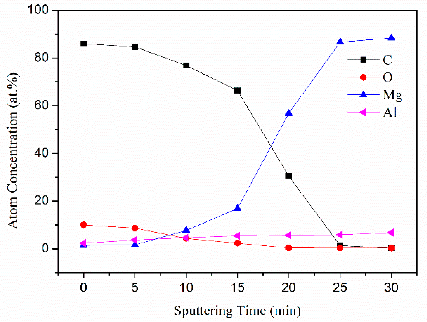
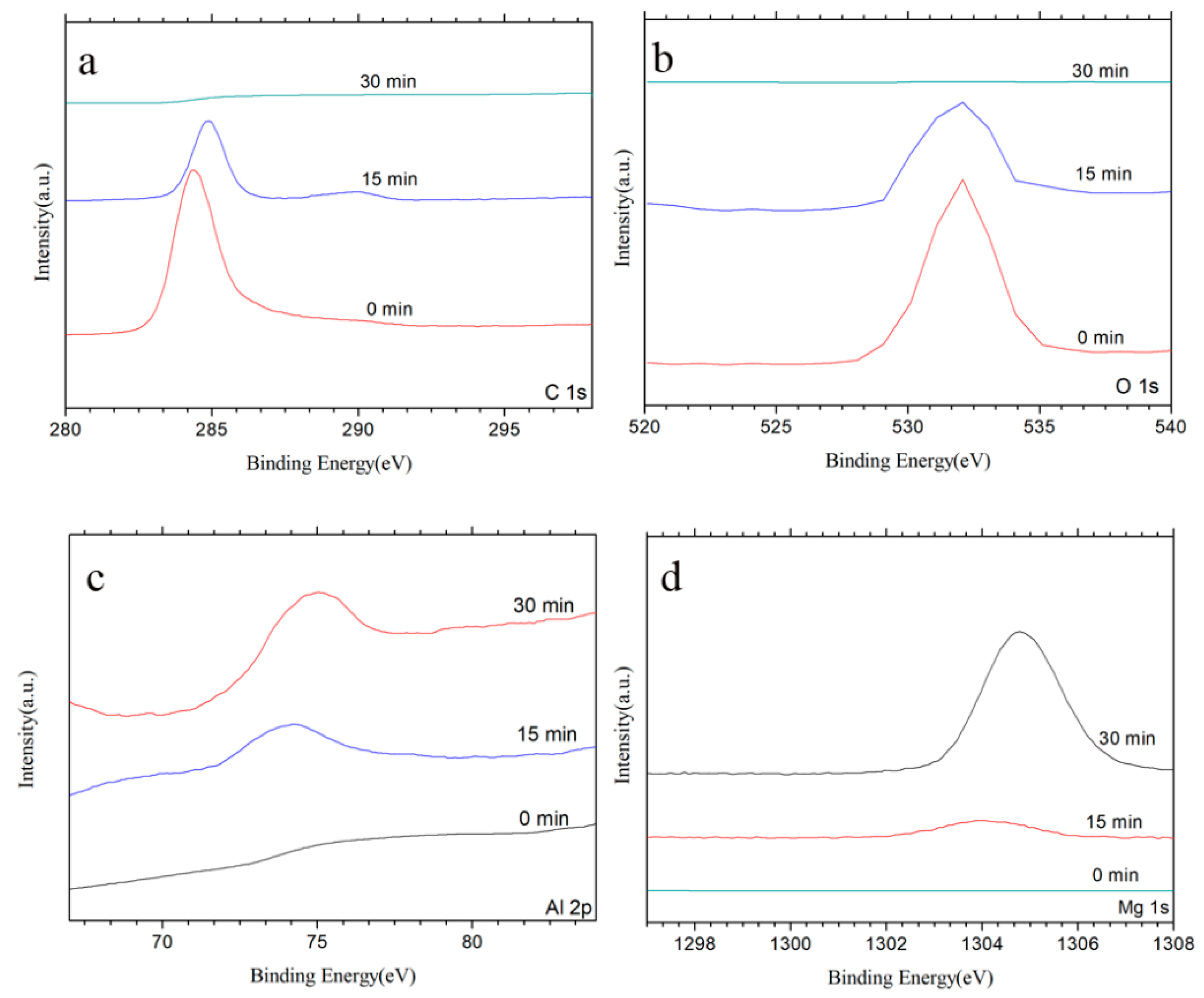
Figure 1 displays the XPS depth profile of the ion-implanted AM60 alloy of Sample C3. A carbon-rich layer is formed after C ion implantation with a depth of about 250 nm. The high-resolution XPS spectra of C, O, Al, and Mg acquired after sputtering for different times are displayed in Figure 2. As the sputtering time increases, the C peak intensity decreases (Figure 2a) and the Mg intensity increases gradually (Figure 2d). The Al intensity also increases (Figure 2c), and O is observed at the sputtering times of 0 and 15 min (Figure 2b). The C binding energy is 284.5 eV (Figure 2a), suggesting a sp2 hybridization composed of three σ bonds and one π bond perpendicular to the σ bond. This observation is consistent with previous results, and it is generally believed that sp2 hybridization is formed by low-energy ion implantation [35,36].
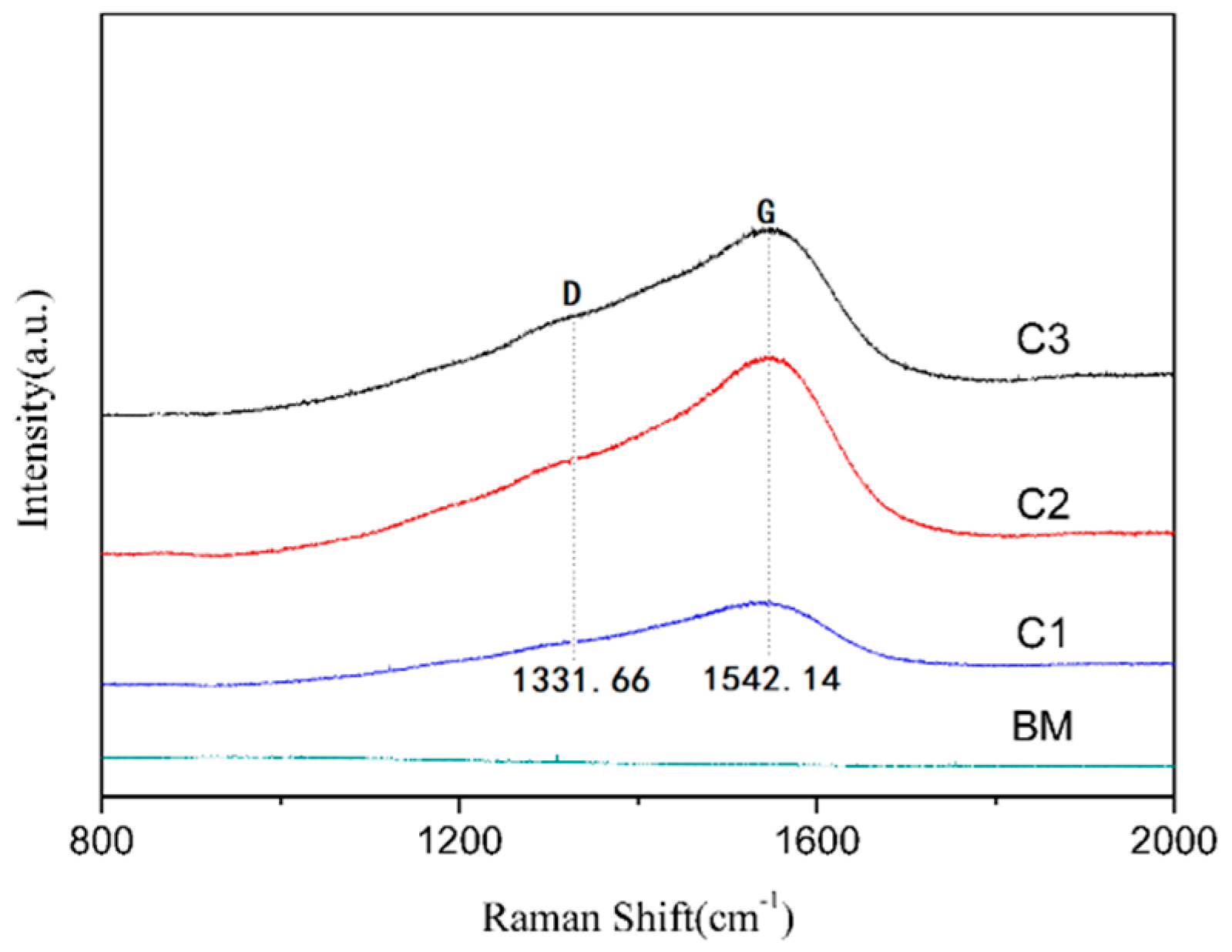
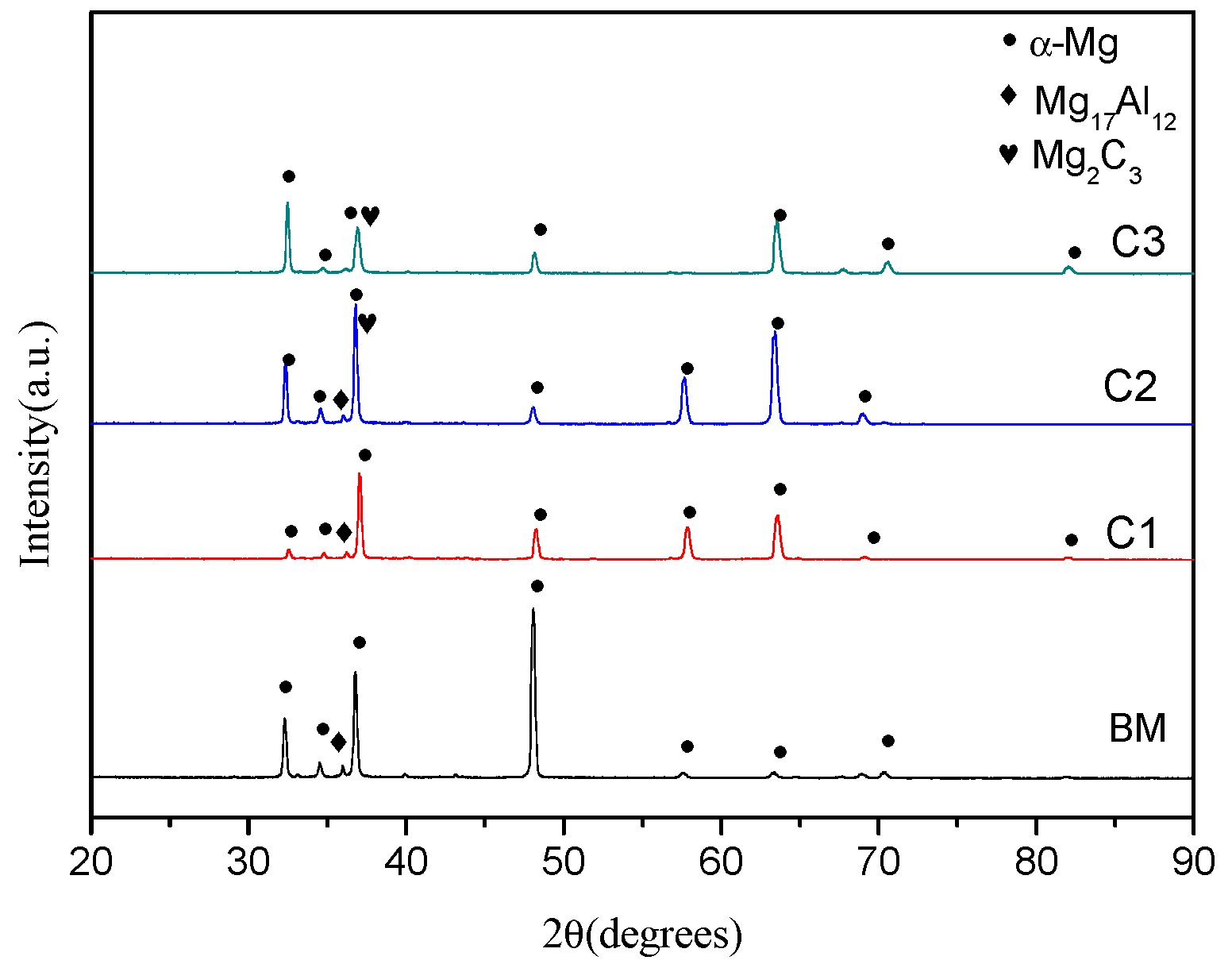
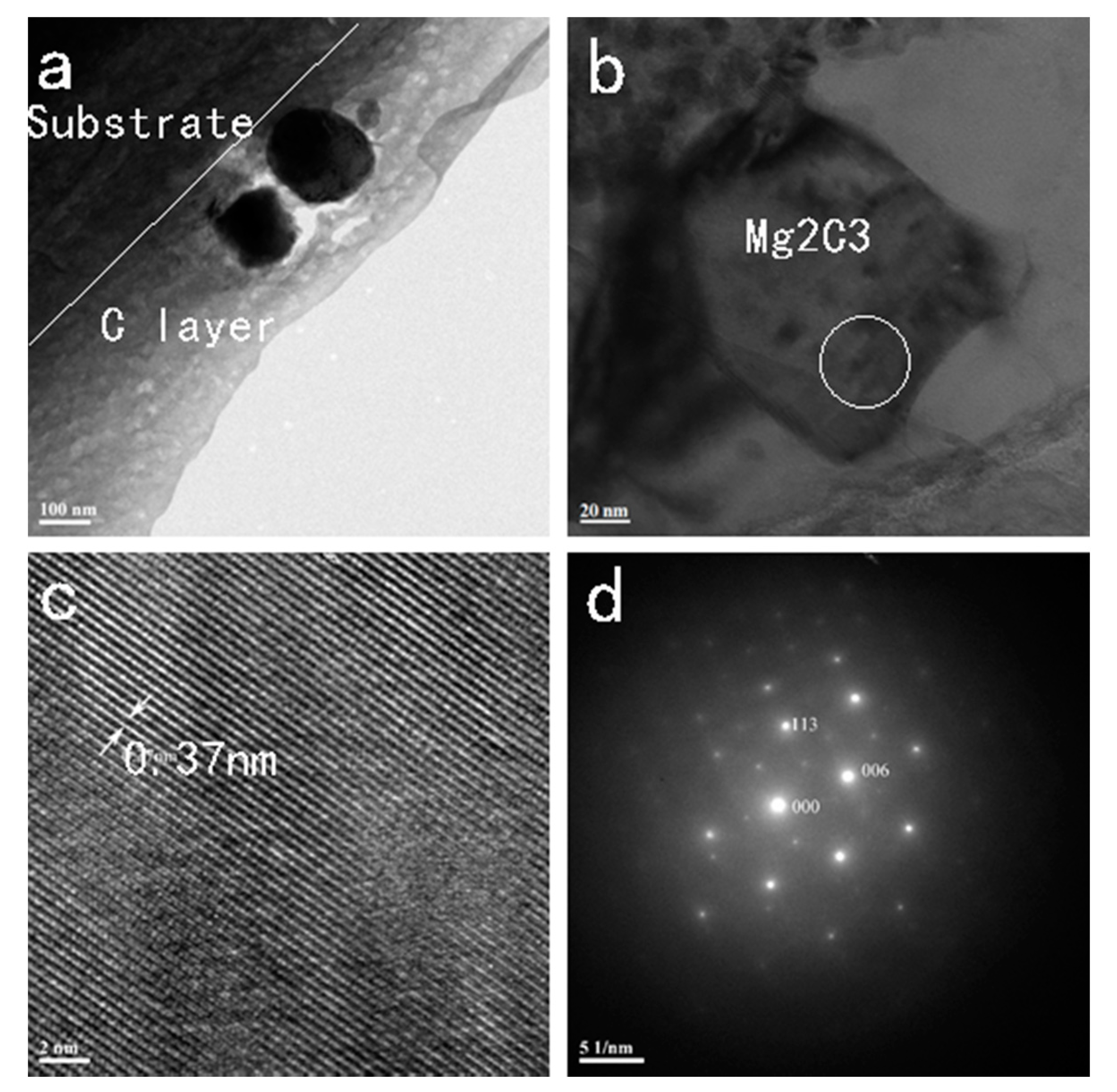
Figure 3 shows the Raman scattering spectra. Before ion implantation, there is no C peak, but after C ion implantation, a G peak at 1542.14 cm−1 and D peak at 1331.66 cm−1 arising from amorphous carbon with sp2 and sp3 hybridization appear, being consistent with the XPS data. Figure 4 shows the XRD patterns, and α-Mg and Mg17Al12 are present. A weak Mg2C3 phase was formed after ion implantation, especially for high fluences such as for Samples C2 and C3. Figure 5 shows the TEM images of Sample C3. Figure 5a shows that the carbon-implanted sample is about 250 nm thick, consistent with the results of XPS. The white line shows the interface between the C layer and substrate. The black objects are the compound formed during ion implantation. A typical compound is revealed in the near surface as shown in Figure 5b. Figure 5c is a higher magnification of part of the white circle area in Figure 5b. The distance of the lattice space of the compound is 0.37 nm. According to the EDS results, the percent of Mg is 34.6%, the percent of C is 61.3%, and the percent of O is 4.1%. The compound is mainly composed of Mg and C. The diffraction patterns of the compound are displayed in Figure 5d. The results of TEM and XRD suggest that the compound is Mg2C3.
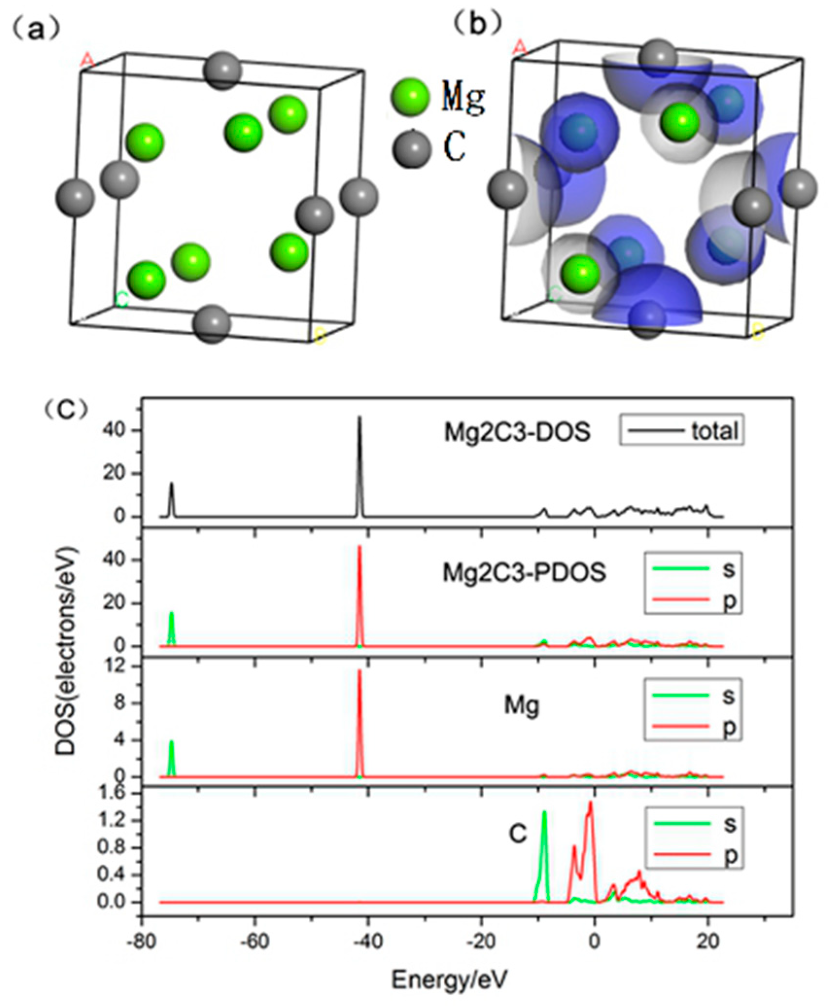
According to Find It soft, Mg2C3 has a complex cubic structure. The Mg2C3 space group is Pnnm (parameter code 58), and a = 6.4108 Å, b = 5.2786 Å, and c = 3.7283 Å, as shown in Table 2. Based on the data, a unit cell model and the electron density map are shown in Figure 6a,b, respectively. Figure 6c shows the density of states (DOS) of the Mg2C3 unit cell, and the large peak shows two kinds of atomic p orbitals. The main electron energy is concentrated between −50 and −40 eV, and the electron energy mainly comes from Mg (p) and Mg (s). In addition, the valence electron of C (s) and C (p) makes a small contribution. The structure is primarily responsible for the improved corrosion resistance, to be discussed later.
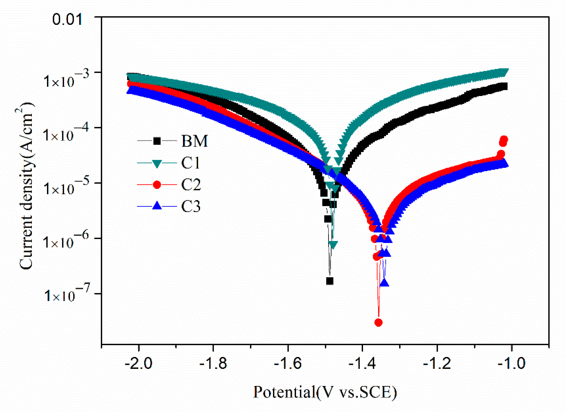
Figure 7 presents the potentiodynamic polarization curves of the different samples in the 3.5% NaCl solution. The corrosion potential (Ecorr) and corrosion current density (Icorr) are determined by Tafel extrapolation. If a tangent is made to the cathodic polarization curve and the anodic polarization curve, the ordinate of the intersection of the two lines and the Ecorr potential line is the Icorr. Compared to that of the un-implanted AM60 control sample, the Ecorr of Sample C3 shifts from −1.48 to −1.35 V, indicative of better corrosion resistance in the NaCl solution. The Icorr of sample C3 is 20.1 μA/cm2, which is much lower than that of the AM60 control sample (50.6 μA/cm2). The more positive Ecorr and smaller Icorr demonstrate that C ion implantation improves the corrosion resistance of the Mg alloy by forming the modified structure as described previously [37,38].
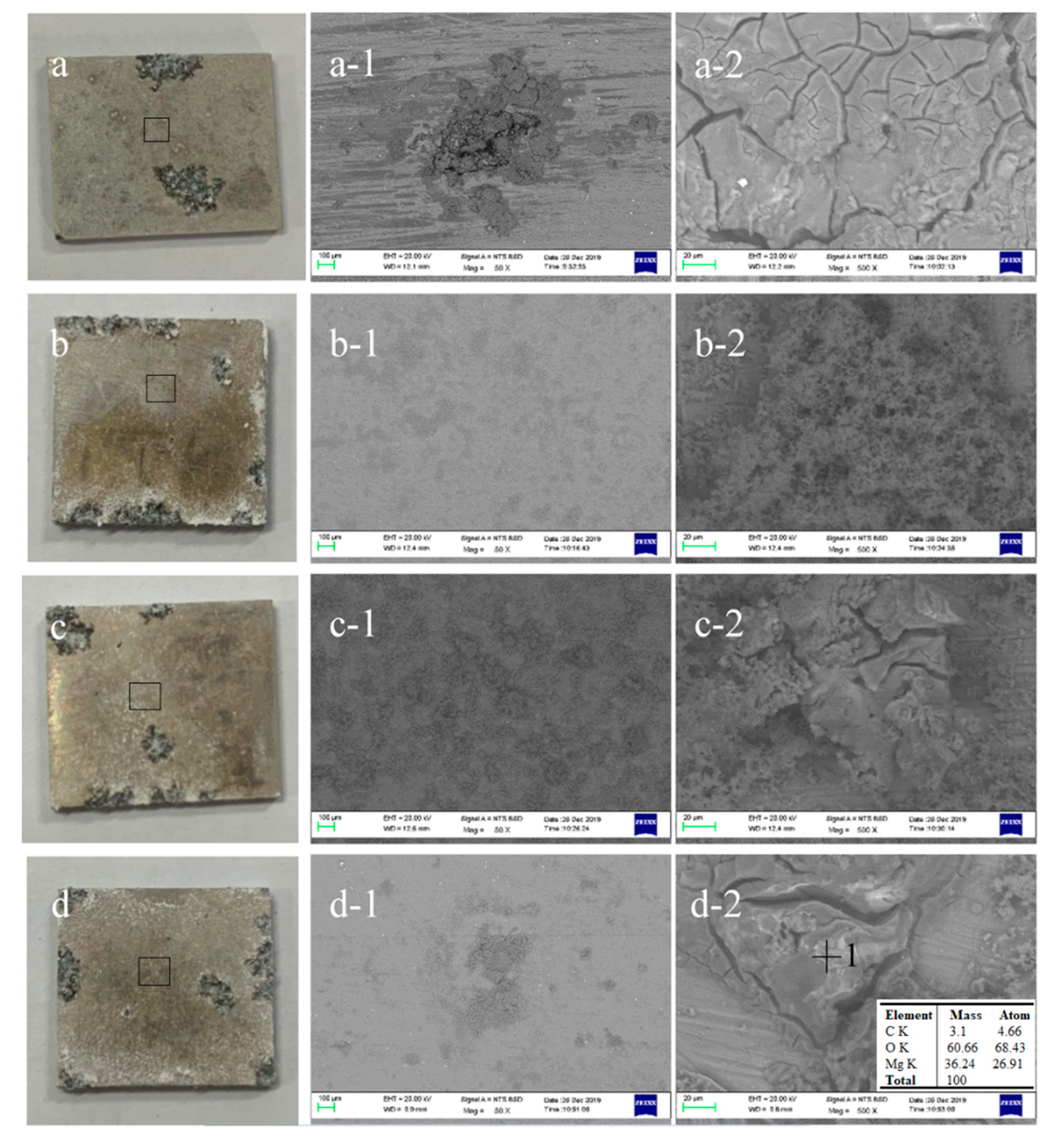
The morphology of the different samples after immersion in 3.5% NaCl is shown in Figure 8. Lots of corrosion defects are observed from the surfaces of the control samples (Figure 8a-2). The SEM images were obtained from the marked part in the black box of the digital picture. It can be seen that the corrosion area of sample BM is larger than that of the other samples. The EDS performed on Point 1 as shown in Figure 8d-2 indicates that there are Mg, O, and C elements on the surface after C ion implantation.
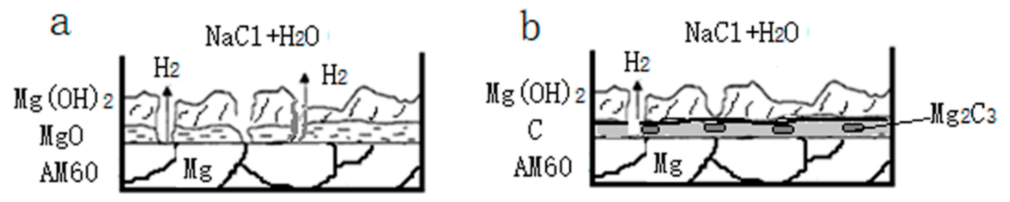
Figure 9 is the schematic presentation of the corrosion of the different samples. The inner layer is composed of AM60 alloy, and a thin layer of MgO is attached to the outer layer. The MgO layer on the surface is hydrated during exposure to an aqueous environment, which converts the MgO into a larger stable Mg(OH)2 layer [24], and H2 is produced in the corrosion process as shown in Figure 9a. The reaction may be expressed as the sum of the following reactions:
Mg = Mg2+ + 2e (anodic reaction)
2H2O + 2e = H2 + 2(OH)− (cathodic reaction)
Mg2+ + 2(OH)− = Mg(OH)2 (product formation)
Mg + 2H2O = Mg(OH)2 + H2 (overall reaction)
The anodic reaction (Equation (1)) probably involves intermediate steps, which may produce the monovalent magnesium ion (Mg+), which has a short lifetime [39]. The reduction process for hydrogen ions and the hydrogen overvoltage of the cathodic phase play an important role in the corrosion of magnesium [40]. After C ion implantation, there is a C layer on the surface. The sample from C ion implantation gives rise to better corrosion resistance. Mg2C3 scattered in the C layer and C layer can decrease the corrosion and prevent corrosion from entering the substrate as shown in Figure 9b.
4. Conclusions
- (1)
- A 250 nm-thick C-rich coating is formed on the surface of AM60 after C implantation with an ion implantation dose of 6 × 10¹⁶ ions/cm2, and a Mg2C3 phase is observed from the ion-implanted region.
- (2)
- The large peak in the density of states (DOS) shows the two atomic p orbitals of Mg2C3. The main electron energy is concentrated between −50 and −40 eV, and the electron energy mainly comes from Mg (p) and Mg (s).
- (3)
- The more positive Ecorr and smaller Icorr demonstrate that C ion implantation gives rise to better corrosion resistance in AM60 magnesium alloys.
Author Contributions
Conceptualization, J.D. and P.K.C.; methodology, J.D. and Z.L.; software, Z.L. and B.Y.; validation, B.Y.; formal analysis, Q.R.; investigation, Z.L.; resources, J.D.; data curation, B.Y. and Q.R.; writing—original draft preparation, Z.L. and B.Y.; writing—review and editing, J.D. and P.K.C.; visualization, J.D.; supervision, J.D. and P.K.C.; project administration, P.K.C.; funding acquisition, J.D. and P.K.C. All authors have read and agreed to the published version of the manuscript.
Funding
The research was financially supported by the postdoctoral research funding plan in Jiangsu province under Grant No. 2018K055C, Jiangsu Shuang-Chuang project and City University of Hong Kong Strategic Research Grants (SRG) Nos. 7005105 and 7005264.
Acknowledgments
The authors would like to thank Xin Tong of City University of Hong Kong for providing assistance in the ion implantation experiments.
Conflicts of Interest
There are no conflicts of interest to declare.
References
- Staiger, M.P.; Pietak, A.M.; Huadmai, J.; Dias, G. Magnesium and its alloys as orthopedic biomaterials: A review. Biomaterials 2006, 27, 1728–1734. [Google Scholar] [CrossRef]
- Gray, J.E.; Luan, B. Protective coatings on magnesium and its alloys—A critical review. J. Alloys Compd. 2002, 336, 88–113. [Google Scholar] [CrossRef]
- Rahmati, M.; Raeissi, K.; Toroghinejad, M.R. Effect of pulse current mode on microstructure, composition and corrosion performance of the coatings produced by plasma electrolytic oxidation on AZ31 Mg alloy. Coatings 2019, 9, 688. [Google Scholar] [CrossRef] [Green Version]
- Hagihara, K.; Li, Z.X.; Yamasaki, M.; Kawamura, Y.; Nakano, T. Strengthening mechanisms acting in extruded Mg-based long-period stacking ordered (LPSO)-phase alloys. Acta Mater. 2019, 163, 226–239. [Google Scholar] [CrossRef]
- Chen, M.S.; Yuan, W.Q.; Li, H.B.; Zou, Z.H. New insights on the relationship between flow stress softening and dynamic recrystallization behavior of magnesium alloy AZ31B. Mater. Charact. 2019, 147, 173–183. [Google Scholar] [CrossRef]
- Johnston, S.; Shi, Z.M.; Atrens, A. The influence of pH on the corrosion rate of high-purity Mg, AZ91 and ZE41 in bicarbonate buffered Hanks’ solution. Corros. Sci. 2015, 101, 182–192. [Google Scholar] [CrossRef] [Green Version]
- Song, D.; Li, C.; Liang, N.N.; Yang, F.L.; Jiang, J.H.; Sun, J.P.; Wu, G.S.; Ma, A.; Ma, X.L. Simultaneously improving corrosion resistance and mechanical properties of a magnesium alloy via equal-channel angular pressing and post water annealing. Mater. Des. 2019, 166, 107621. [Google Scholar] [CrossRef]
- Jian, S.Y.; Ho, M.L.; Shih, B.C. Evaluation of the corrosion resistance and cytocompatibility of a bioactive micro-arc oxidation coating on AZ31 Mg alloy. Coatings 2019, 9, 396. [Google Scholar] [CrossRef] [Green Version]
- Guo, H.F.; An, M.Z. Growth of ceramic coatings on AZ91D magnesium alloys by micro-arc oxidation in aluminate-fluoride solutions and evaluation of corrosion resistance. Appl. Surf. Sci. 2005, 246, 229–238. [Google Scholar] [CrossRef]
- Subramanian, R.; Sircar, S.; Mazumder, J. Laser cladding of Zirconium on magnesium for improved corrosion properties. J. Mater. Sci. 1991, 26, 951–956. [Google Scholar] [CrossRef]
- Volovitch, P.; Masse, J.E.; Fabre, A.; Barrallier, L.; Saikaly, W. Microstructure and corrosion resistance of magnesium alloy ZE41 with laser surface cladding by Al-Si powder. Surf. Coat. Technol. 2008, 202, 4901–4914. [Google Scholar] [CrossRef]
- Wu, G.S.; Jamesh, M.I.; Chu, P.K. Surface design of biodegradable magnesium alloys—A review. Surf. Coat. Technol. 2013, 233, 2–12. [Google Scholar] [CrossRef]
- Zheng, Y.; Zhang, L.B.; Bi, Y.Z. Corrosion behavior of Fe/Zr composite coating on ZK60 Mg alloy by Ion implantation and deposition. Coatings 2018, 8, 261. [Google Scholar] [CrossRef] [Green Version]
- Jin, W.H.; Wu, G.S.; Feng, H.Q.; Wang, W.H.; Zhang, X.M.; Chu, P.K. Improvement of corrosion resistance and biocompatibility of rare-earth WE43 magnesium alloy by neodymium self-ion implantation. Corros. Sci. 2015, 94, 142–155. [Google Scholar] [CrossRef]
- Feliu, S.; Maffiotte, C.; Samaniego, A.; Galvan, J.C.; Barranco, V. Effect of the chemistry and structure of the native oxide surface film on the corrosion properties of commercial AZ31 and AZ61 alloys. Appl. Surf. Sci. 2011, 257, 8558–8568. [Google Scholar] [CrossRef] [Green Version]
- Wan, Y.Z.; Xiong, G.Y.; Luo, H.L.; He, F.; Huang, Y.; Wang, Y.L. Influence of zinc ion implantation on surface nanomechanical performance and corrosion resistance of biomedical magnesium–calcium alloys. Appl. Surf. Sci. 2008, 254, 5514–5516. [Google Scholar] [CrossRef]
- Liu, H.X.; Xu, Q.; Jiang, Y.H.; Wang, C.Q.; Zhang, X.W. Corrosion resistance and mechanical property of AZ31 magnesium alloy by N/Ti duplex ion implantation. Surf. Coat. Technol. 2013, 228, S538–S543. [Google Scholar] [CrossRef]
- Wu, G.S.; Ding, K.J.; Zeng, X.Q.; Wang, X.M.; Yao, S.S. Improving corrosion resistance of titanium-coated magnesium alloy by modifying surface characteristics of magnesium alloy prior to titanium coating deposition. Scr. Mater. 2009, 61, 269–272. [Google Scholar] [CrossRef]
- Xie, Z.W.; Chen, Q.; Chen, T.; Gao, X.; Yu, X.G.; Song, H.; Feng, Y.J. Microstructure and properties of nitrogen ion implantation/AlN/CrAlN/MoS2-phenolic resin duplex coatings on magnesium alloys. Mater. Chem. Phys. 2015, 160, 212–220. [Google Scholar] [CrossRef]
- Zhu, X.M.; Yang, H.G.; Lei, M.K. Corrosion resistance of Al ion implanted AZ31 magnesium alloy at elevated temperature. Surf. Coat. Technol. 2007, 201, 6663–6666. [Google Scholar] [CrossRef]
- Jamesh, M.I.; Wu, G.S.; Zhao, Y.; Jin, W.H.; McKenzie, D.R.; Bilek, M.M.; Chu, P.K. Effects of zirconium and nitrogen plasma immersion ion implantation on the electrochemical corrosion behavior of Mg–Y–RE alloy in simulated body fluid and cell culture medium. Corros. Sci. 2014, 86, 239–251. [Google Scholar] [CrossRef]
- Jamesh, M.I.; Wu, G.S.; Zhao, Y.; Jin, W.H.; McKenzie, D.R.; Bilek, M.M.; Chu, P.K. Effects of zirconium and oxygen plasma ion implantation on the corrosion behavior of ZK60 Mg alloy in simulated body fluids. Corros. Sci. 2014, 82, 7–26. [Google Scholar] [CrossRef]
- Staišiunas, L.; Miečinskas, P.; Leinartas, K.; Selskis, A.; Grigucevičienė, A.; Juzeliunas, E. Sputter-deposited Mg–Al–Zn–Cr alloys-Electrochemical characterization of single films and multilayer protection of AZ31magnesium alloy. Corros. Sci. 2014, 80, 487–493. [Google Scholar]
- Xu, R.Z.; Wu, G.S.; Yang, X.B.; Zhang, X.M.; Wu, Z.W.; Sun, G.Y.; Li, G.Y.; Chu, P.K. Corrosion behavior of chromium and oxygen plasma-modified magnesium in sulfate solution and simulated body fluid. Appl. Surf. Sci. 2012, 258, 8273–8278. [Google Scholar] [CrossRef]
- Wu, G.S.; Zhang, X.M.; Zhao, Y.; Jamesh, M.I.; Yuan, G.Y.; Chu, P.K. Plasma modified Mg–Nd–Zn–Zr alloy with enhanced surface corrosion resistance. Corros. Sci. 2014, 78, 121–129. [Google Scholar]
- Höche, D.; Blawert, C.; Cavellier, M.; Busardo, D.; Gloriant, T. Magnesium nitride phase formation by means of ion beam implantation technique. Appl. Surf. Sci. 2011, 257, 5626–5633. [Google Scholar] [CrossRef] [Green Version]
- Li, Z.C.; Shang, Z.Z.; Wei, X.; Zhao, Q. Corrosion resistance and cytotoxicity of AZ31 magnesium alloy with N+ ion implantation. Mater. Technol. 2019, 34, 730–736. [Google Scholar] [CrossRef]
- Jamesh, M.I.; Wu, G.S.; Zhao, Y.; Chu, P.K. Effects of silicon plasma ion implantation on electrochemical corrosion behavior of biodegradable Mg–Y–RE Alloy. Corros. Sci. 2013, 69, 158–163. [Google Scholar] [CrossRef]
- Zhao, Y.; Jamesh, M.I.; Li, W.K.; Wu, G.S.; Wang, C.X.; Zheng, Y.F.; Yeung, K.W.K.; Chu, P.K. Enhanced antimicrobial properties, cytocompatibility, and corrosion resistance of plasma-modified biodegradable magnesium alloys. Acta Biomater. 2014, 10, 544–556. [Google Scholar] [CrossRef]
- Burlaka, L.; Kutsenko, L.; Talianker, M.; Fuks, D.; Kiv, A.; Brown, I. Observation of ε-Ag17 Mg54 phase induced by plasma immersion ion implantation. Radiat. Eff. Defect. S. 2013, 168, 631–635. [Google Scholar] [CrossRef]
- Xu, R.Z.; Yang, X.B.; Li, P.H.; Suen, K.W.; Wu, S.; Chu, P.K. Eelectrochemical properties and corrosion resistance of carbon-ion-implanted magnesium. Corros. Sci. 2014, 82, 173–179. [Google Scholar] [CrossRef]
- Marpaung, F.; Park, T.; Kim, M.; Yi, J.W.; Lin, J.J.; Wang, J.; Ding, B.; Lim, H.; Konstantinov, K.; Yamauchi, Y. Gram-Scale Synthesis of Bimetallic ZIFs and Their Thermal Conversion to Nanoporous Carbon Materials. Nanomaterials 2019, 9, 1796. [Google Scholar] [CrossRef] [PubMed] [Green Version]
- Song, H.; Chen, G.; Chen, J.; Li, H.X.; Ji, L.; Jiang, N. Improving the Wear Life of a-C:H Film in High Vacuum by Self-Assembled Reduced Graphene Oxide Layers. Nanomaterials 2019, 9, 1733. [Google Scholar] [CrossRef] [PubMed] [Green Version]
- Zhang, Y.; Guo, D.; Geng, H. Characterization of M-class genome segments of muscovy duck reovirus S14. Virus Res. 2007, 125, 42–53. [Google Scholar] [CrossRef]
- Chu, P.K.; Chen, J.Y.; Wang, L.P.; Huang, N. Plasma-surface modification of biomaterials. Mater. Sci. Eng. R 2002, 36, 143–206. [Google Scholar] [CrossRef] [Green Version]
- Zou, Y.S.; Wu, Y.F.; Yang, H.; Cang, K.; Song, G.H.; Li, Z.X.; Zhou, K. The microstructure, mechanical and friction properties of protective diamond like carbon films on magnesium alloy. Appl. Surf. Sci. 2011, 258, 1624–1629. [Google Scholar] [CrossRef]
- Toorani, M.; Aliofkhazraei, M.; Rouhaghdam, A.S. Microstructural, protective, inhibitory and semiconducting properties of PEO coatings containing CeO2 nanoparticles formed on AZ31 Mg alloy. Surf. Coat. Technol. 2018, 352, 561–580. [Google Scholar] [CrossRef]
- Toorani, M.; Aliofkhazraei, M. Review of electrochemical properties of hybrid coating systems on Mg with plasma electrolytic oxidation process as pretreatment. Surf. Interfaces 2019, 14, 262–295. [Google Scholar] [CrossRef]
- Makar, G.L.; Kruger, J. Corrosion studies of rapidly solidified magnesium alloys. J. Electrochem. Soc. 1990, 137, 414–421. [Google Scholar] [CrossRef]
- Song, G.L.; Atrens, A. Corrosion Mechanisms of Magnesium Alloys. Adv. Eng. Mater. 1999, 1, 11–33. [Google Scholar] [CrossRef]
Figure 1.
XPS element depth profile of the AM60 alloy after C ion implantation at 6 × 10⁶ ions/cm2 with a sputtering rate of 10 nm/min.
Figure 1.
XPS element depth profile of the AM60 alloy after C ion implantation at 6 × 10⁶ ions/cm2 with a sputtering rate of 10 nm/min.

Figure 2.
High-resolution XPS spectra of the treated AM60 alloy at 6 × 10⁶ ions/cm2 after sputtering for different times: (a) C 1s, (b) O 1s, (c) Al 2p, and (d) Mg 1s.
Figure 2.
High-resolution XPS spectra of the treated AM60 alloy at 6 × 10⁶ ions/cm2 after sputtering for different times: (a) C 1s, (b) O 1s, (c) Al 2p, and (d) Mg 1s.

Figure 3.
Raman scattering spectra of the carbon films.

Figure 4.
XRD patterns of different samples.

Figure 5.
Cross-sectional TEM images of Sample C3: (a) surface microstructure, (b) compound microstructure, (c) high resolution TEM images, and (d) diffraction patterns of the compound.
Figure 5.
Cross-sectional TEM images of Sample C3: (a) surface microstructure, (b) compound microstructure, (c) high resolution TEM images, and (d) diffraction patterns of the compound.

Figure 6.
First-principle study of Mg2C3: (a) unit cell model, (b) electron density map, and (c) state density maps.
Figure 6.
First-principle study of Mg2C3: (a) unit cell model, (b) electron density map, and (c) state density maps.

Figure 7.
Polarization curves of different samples.

Figure 8.
Morphology of the corroded samples: (a) BM, (b) C1, (c) C2, and (d) C3; (i-1) low-magnification SEM pictures, and (i-2) high-magnification SEM pictures. EDS results acquired from Point 1 (i = a, b, c, and d).
Figure 8.
Morphology of the corroded samples: (a) BM, (b) C1, (c) C2, and (d) C3; (i-1) low-magnification SEM pictures, and (i-2) high-magnification SEM pictures. EDS results acquired from Point 1 (i = a, b, c, and d).

Figure 9.
A schematic presentation of the corrosion of different samples: (a) corrosion of AM60 Mg alloy, and (b) corrosion of AM60 with C nanolayer.
Figure 9.
A schematic presentation of the corrosion of different samples: (a) corrosion of AM60 Mg alloy, and (b) corrosion of AM60 with C nanolayer.


Table 1.
Carbon ion implantation fluences.
| Samples | BM | C1 | C2 | C3 |
|---|---|---|---|---|
| Fluence (ions/cm2) | 0 | 1 × 10¹⁶ | 3 × 10¹⁶ | 6 × 10¹⁶ |
Table 2.
Lattice parameters of Mg2C3.
| Crystal | Space Group | Lattice Parameters | Elements | Atomic Coordinates | ||||
|---|---|---|---|---|---|---|---|---|
| a | b | c | X | Y | Z | |||
| Mg2C3 | 58 | 6.4108 | 5.2786 | 3.7283 | Mg(I) | 0.2903 | 0.3901 | 0 |
| C(I) | 0.5 | 0 | 0 | |||||
| C(II) | 0.6188 | 0.2070 | 0 | |||||
© 2020 by the authors. Licensee MDPI, Basel, Switzerland. This article is an open access article distributed under the terms and conditions of the Creative Commons Attribution (CC BY) license (http://creativecommons.org/licenses/by/4.0/).
Share and Cite
MDPI and ACS Style
Yu, B.; Dai, J.; Ruan, Q.; Liu, Z.; Chu, P.K. Corrosion Behavior and Mechanism of Carbon Ion-Implanted Magnesium Alloy. Coatings 2020, 10, 734. https://doi.org/10.3390/coatings10080734
AMA Style
Yu B, Dai J, Ruan Q, Liu Z, Chu PK. Corrosion Behavior and Mechanism of Carbon Ion-Implanted Magnesium Alloy. Coatings. 2020; 10(8):734. https://doi.org/10.3390/coatings10080734
Chicago/Turabian StyleYu, Banglong, Jun Dai, Qingdong Ruan, Zili Liu, and Paul K. Chu. 2020. "Corrosion Behavior and Mechanism of Carbon Ion-Implanted Magnesium Alloy" Coatings 10, no. 8: 734. https://doi.org/10.3390/coatings10080734
Note that from the first issue of 2016, this journal uses article numbers instead of page numbers. See further details here.