Research Progress of Failure Mechanism of Thermal Barrier Coatings at High Temperature via Finite Element Method


Abstract
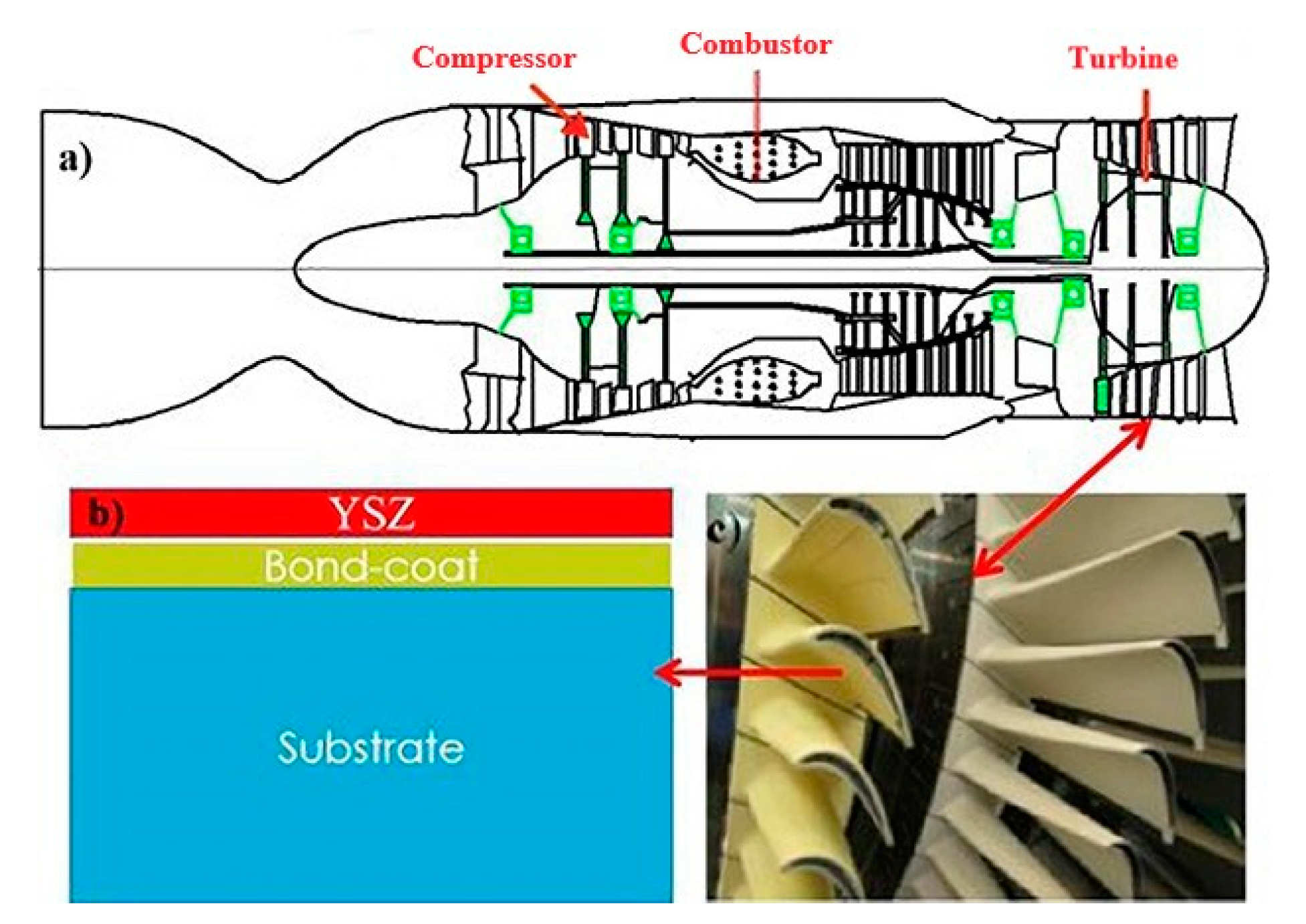
:1. Introduction
2. Structure and Preparation Technology of TBCs
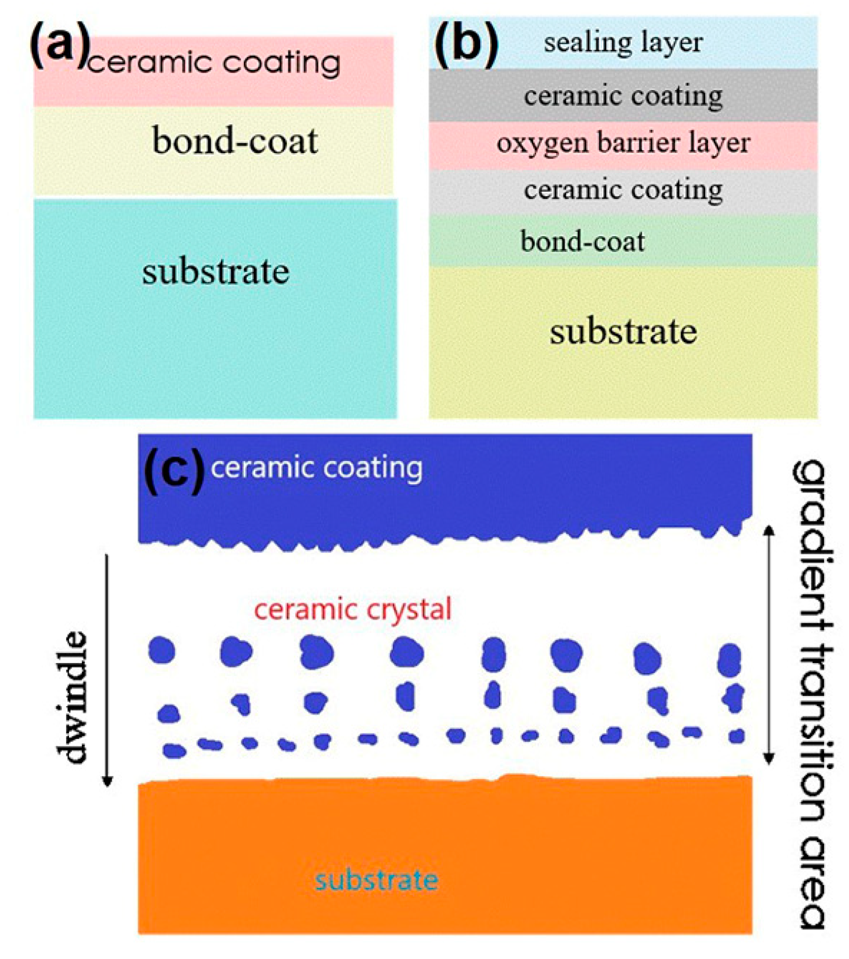
2.1. Structure Model of TBCs
2.1.1. Double-Layer Structure Coating
2.1.2. Multi-Layer Structure Coating Model
2.1.3. Functional Graded Thermal Barrier Coatings Model
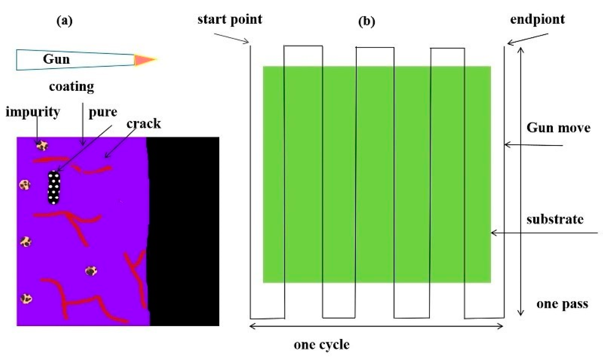
2.2. Preparation Technology of Thermal Barrier Coatings
2.2.1. EB-PVD
2.2.2. PS-PVD
2.2.3. APS
3. The Factors Affecting the Service Lifetime of TBCs
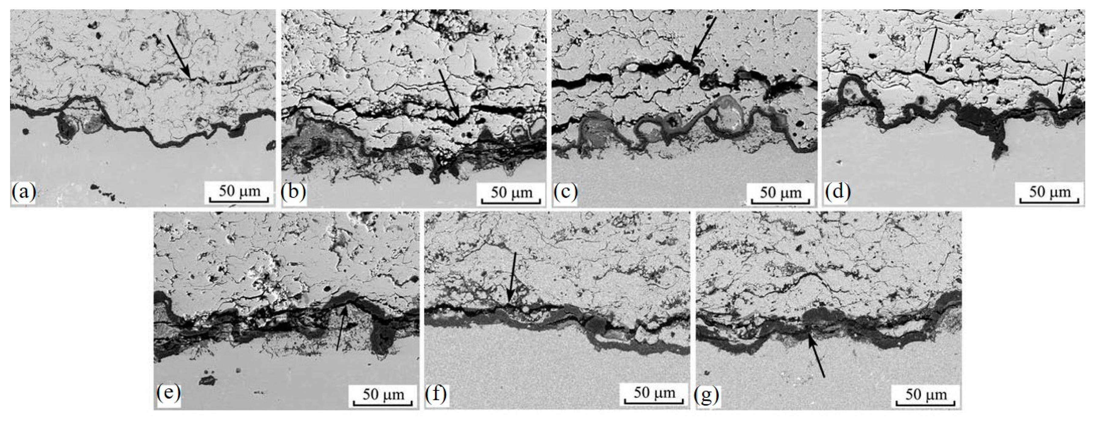
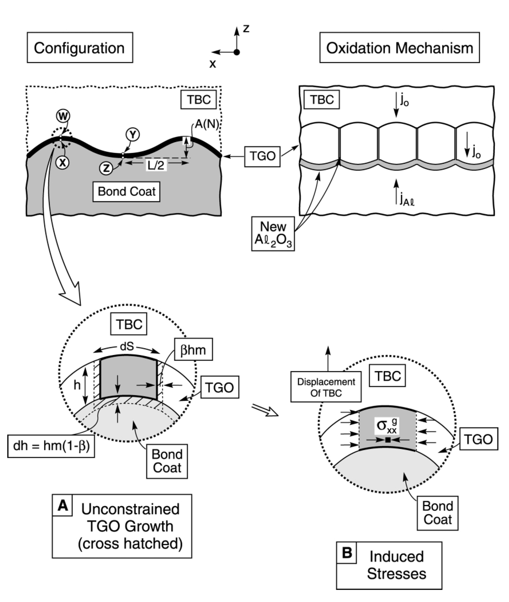
3.1. TGO
3.2. Thermal Expansion Mismatch
3.3. Roughness of the Interface
3.4. Foreign Object Damage
3.5. CMAS Corrosion of Thermal Barrier Coating
4. Conclusions and Prospects
- The performance of the material is dependent on the microstructure of the material. The dual-ceramic coating has higher thermal insulation performance and can greatly prolong the thermal cycle life of the coating, improving the service temperature of the coating significantly. It is one of the effective ways to develop ultra-high temperature TBCs in the future.
- At present, the factors affecting the service lifetime of TBCs, such as TGO, thermal mismatch, and high temperature corrosion, are being studied. The damage of TBCs caused by CMAS at high temperature is emphasized. However, it should not be ignored that the uneven growth of TGO will cause the accumulation of residual stress and affect the distribution of interfacial stress. Additionally, the mechanism of the influence of the distribution of horizontal and vertical cracks on the stress around TGO during thermal cycling is revealed by finite element simulation. The thermal shock resistance of the coating can be further improved by controlling the density of the segmentation cracks.
Author Contributions
Funding
Conflicts of Interest
References
- Mosayebnezhad, M.; Mehr, A.S.; Lanzini, A.; Misul, D.; Santarelli, M. Technology review and thermodynamic performance study of a biogas-fed micro humid air turbine. Renew. Energy 2019, 140, 407–418. [Google Scholar] [CrossRef]
- Rabiei, A.; Evans, A.G. Failure mechanisms associated with the thermally grown oxide in plasma-sprayed thermal barrier coatings. Acta Mater. 2000, 48, 3963–3976. [Google Scholar] [CrossRef]
- Evans, A.G.; Clarke, D.R.; Levi, C.G. The influence of oxides on the performance of advanced gas turbines. J. Eur. Ceram. Soc. 2008, 28, 1405–1419. [Google Scholar] [CrossRef]
- Carter, T.J. Common failures in gas turbine blades. Eng. Fail. Anal. 2005, 12, 237–247. [Google Scholar] [CrossRef]
- Tolpygo, V.K.; Clarke, D.R.; Murphy, K.S. Evaluation of interface degradation during cyclic oxidation of EB-PVD thermal barrier coatings and correlation with TGO luminescence. Surf. Coat. Technol. 2004, 188, 62–70. [Google Scholar] [CrossRef]
- Clarke, D.R.; Levi, C.G. Materials design for the next generation thermal barrier coatings. Annu. Rev. Mater. Res. 2003, 33, 383–417. [Google Scholar] [CrossRef]
- Evans, A.G.; He, M.Y.; Hutchinson, J.W. Mechanics-based scaling laws for the durability of thermal barrier coatings. Prog. Mater. Sci. 2001, 46, 249–271. [Google Scholar] [CrossRef]
- Evans, A.G.; Mumm, D.R.; Hutchinson, J.W.; Meier, G.H.; Pettit, F.S. Mechanisms controlling the durability of thermal barrier coatings. Prog. Mater. Sci. 2001, 46, 505–553. [Google Scholar] [CrossRef]
- Levi, C.G. Emerging materials and processes for thermal barrier systems. Curr. Opin. Solid State Mater. Sci. 2004, 8, 77–91. [Google Scholar] [CrossRef]
- Mumm, D.R.; Evans, A.G. Mechanisms controlling the performance and durability of thermal barrier coatings. Key Eng. Mater. 2001, 197, 199–230. [Google Scholar] [CrossRef]
- Padture, N.P.; Gell, M.; Jordan, E.H. Materials science—Thermal barrier coatings for gas-turbine engine applications. Science 2002, 296, 280–284. [Google Scholar] [CrossRef] [PubMed]
- Wang, L.; Zhao, Y.X.; Zhong, X.H.; Tao, S.Y.; Zhang, W.; Wang, Y. Influence of “island-like” oxides in the bond-coat on the stress and failure patterns of the thermal-barrier coatings fabricated by atmospheric plasma spraying during long-term high temperature oxidation. J. Therm. Spray Technol. 2014, 23, 431–446. [Google Scholar] [CrossRef]
- Wang, L.; Yang, J.S.; Ni, J.X.; Liu, C.G.; Zhong, X.H.; Shao, F.; Zhao, H.Y.; Tao, S.Y.; Wang, Y. Influence of cracks in APS-TBCs on stress around TGO during thermal cycling: A numerical simulation study. Surf. Coat. Technol. 2016, 285, 98–112. [Google Scholar] [CrossRef]
- Wang, L.; Wang, Y.; Zhang, W.Q.; Sun, X.G.; He, J.Q.; Pan, Z.Y.; Wang, C.H. Finite element simulation of stress distribution and development in 8YSZ and double-ceramic-layer La2Zr2O7/8YSZ thermal barrier coatings during thermal shock. Appl. Surf. Sci. 2012, 258, 3540–3551. [Google Scholar] [CrossRef]
- Gupta, M.; Nylen, P.; Wigren, J. A Modelling approach to designing microstructures in thermal barrier coatings. J. Ceram. Sci. Technol. 2013, 4, 85–91. [Google Scholar]
- Wang, L.; Ming, C.; Zhong, X.H.; Ni, J.X.; Tao, S.Y.; Zhou, F.F.; Wang, Y. Prediction of critical rupture of plasma-sprayed yttria stabilized zirconia thermal barrier coatings under burner rig test via finite element simulation and in-situ acoustic emission technique. Surf. Coat. Technol. 2019, 367, 58–74. [Google Scholar] [CrossRef]
- Shanian, A.; Milani, A.S.; Vermaak, N.; Bertoldi, K.; Scarinci, T.; Gerendas, M. A combined finite element-multiple criteria optimization approach for materials selection of gas turbine components. J. Appl. Mech. 2012, 79, 061019. [Google Scholar] [CrossRef]
- Tsipas, S.A.; Golosnoy, I.O. Effect of substrate temperature on the microstructure and properties of thick plasma-sprayed YSZ TBCs. J. Eur. Ceram Soc. 2011, 31, 2923–2929. [Google Scholar] [CrossRef] [Green Version]
- Cerri, E.; Maci, S.; Leo, P.; Zanon, G.; Petrachi, M.R. High temperature oxidation behaviour of CoCrTaAlY + 10%Al2O3 coatings produced by HVOF. Metall. Ital. 2013, 105, 13–20. [Google Scholar]
- Rajendran, V.; Dhineshbabu, N.R.; Kanna, R.R.; Kaler, K.V.I.S. Enhancement of thermal stability, flame retardancy, and antimicrobial properties of cotton fabrics functionalized by inorganic nanocomposites. Ind. Eng. Chem. Res. 2014, 53, 19512–19524. [Google Scholar] [CrossRef]
- Yang, Y.; Wang, Y.; Tian, W.; Yan, D.R.; Zhang, J.X.; Wang, L. Influence of composite powders’ microstructure on the microstructure and properties of Al2O3-TiO2 coatings fabricated by plasma spraying. Mater. Des. 2015, 65, 814–822. [Google Scholar] [CrossRef]
- Yang, Y.; Yan, D.R.; Dong, Y.C.; Chen, X.G.; Wang, L.; Chu, Z.H.; Zhang, J.X.; He, J.N. Preparing of nanostructured Al2O3-TiO2-ZrO2 composite powders and plasma spraying nanostructured composite coating. Vacuum 2013, 96, 39–45. [Google Scholar] [CrossRef]
- Alami, A.H.; Allagui, A.; Alawadhi, H. Microstructural and optical studies of CuO thin films prepared by chemical ageing of copper substrate in alkaline ammonia solution. J. Alloy. Compd. 2014, 617, 542–546. [Google Scholar] [CrossRef]
- Hasegawa, M.; Endo, T.; Fukutomi, H. Effects of heat exposure time and temperature on the delamination behavior of air plasma-sprayed thermal barrier coatings under shear loading. Mater. Trans. 2016, 57, 1138–1146. [Google Scholar] [CrossRef] [Green Version]
- Xu, Z.H.; He, L.M.; Mu, R.D.; Zhong, X.H.; Zhang, Y.F.; Zhang, J.F.; Cao, X.Q. Double-ceramic-layer thermal barrier coatings of La2Zr2O7/YSZ deposited by electron beam-physical vapor deposition. J. Alloy. Compd. 2009, 473, 509–515. [Google Scholar] [CrossRef]
- Yang, C.X.; Li, Z.X.; Liu, L.T.; Ye, F.; Wu, S.J. High temperature behavior of a diffusion barrier coating evolved from ZrO2 precursor layer. Surf. Coat. Technol. 2019, 357, 384–392. [Google Scholar] [CrossRef]
- Taymaz, I.; Mimaroglu, A.; Avci, E.; Ucar, V.; Gur, M. Comparison of thermal stresses developed in Al2O3-SG, ZrO2-(12% Si + Al) and ZrO2-SG thermal barrier coating systems with NiAl, NiCrAlY and NiCoCrAlY interlayer materials subjected to thermal loading. Surf. Coat. Technol. 1999, 116, 690–693. [Google Scholar] [CrossRef]
- Deng, Z.Q.; Zhang, X.F.; Zhou, K.S.; Liu, M.; Deng, C.M.; Mao, J.; Chen, Z.K. 7YSZ coating prepared by PS-PVD based on heterogeneous nucleation. Chin. J. Aeronaut. 2018, 31, 820–825. [Google Scholar] [CrossRef]
- Nagabhushana, N.; Rajanna, S.; Mathapati, M.; Ramesh, M.R.; Koppad, P.G.; Reddy, N.C. Microstructure and tribological characteristics of APS sprayed NiCrBSi/flyash cenosphere/Cr2O3 and NiCrBSi/flyash cenosphere/Mo composite coatings at elevated temperatures. Mater. Res. Express 2019, 6, 086451. [Google Scholar] [CrossRef]
- Darolia, R. Thermal barrier coatings technology: Critical review, progress update, remaining challenges and prospects. Int. Mater. Rev. 2013, 58, 315–348. [Google Scholar] [CrossRef]
- Yang, J.S.; Zhao, H.Y.; Zhong, X.H.; Ni, J.X.; Zhuang, Y.; Wang, L.; Tao, S.Y. Evolution of residual stresses in PS-PVD thermal barrier coatings on thermal cycling. J. Therm. Spray Technol. 2018, 27, 914–923. [Google Scholar] [CrossRef]
- Rezanka, S.; Somsen, C.; Eggeler, G.; Mauer, G.; Vassen, R.; Guillon, O. A TEM Investigation of columnar-structured thermal barrier coatings deposited by plasma spray-physical vapor deposition (PS-PVD). Plasma Chem. Plasma Process. 2018, 38, 791–802. [Google Scholar] [CrossRef]
- Rezanka, S.; Mack, D.E.; Mauer, G.; Sebold, D.; Guillon, O.; Vassen, R. Investigation of the resistance of open-column-structured PS-PVD TBCs to erosive and high-temperature corrosive attack. Surf. Coat. Technol. 2017, 324, 222–235. [Google Scholar] [CrossRef]
- Gao, L.H.; Guo, H.B.; Wei, L.L.; Li, C.Y.; Xu, H.B. Microstructure, thermal conductivity and thermal cycling behavior of thermal barrier coatings prepared by plasma spray physical vapor deposition. Surf. Coat. Technol. 2015, 276, 424–430. [Google Scholar] [CrossRef]
- Philips, N.R.; Levi, C.G.; Evans, A.G. Mechanisms of microstructure evolution in an austenitic stainless steel bond generated using a quaternary braze alloy. Metall. Mater. Trans. A 2008, 39, 142–149. [Google Scholar] [CrossRef]
- Crowell, M.W.; Schaedler, T.A.; Hazel, B.H.; Konitzer, D.G.; McMeeking, R.M.; Evans, A.G. Experiments and numerical simulations of single particle foreign object damage-like impacts of thermal barrier coatings. Int. J. Impact Eng. 2012, 48, 116–124. [Google Scholar] [CrossRef]
- Wei, Z.Y.; Cai, H.N.; Feng, R.X.; Su, J.Y. Dynamic crack growth mechanism and lifetime assessment in plasma sprayed thermal barrier system upon temperature cycling. Ceram. Int. 2019, 45, 14896–14907. [Google Scholar] [CrossRef]
- Wei, Z.Y.; Cai, H.N. Stress states and crack behavior in plasma sprayed TBCs based on a novel lamellar structure model with real interface morphology. Ceram. Int. 2019, 45, 16948–16962. [Google Scholar] [CrossRef]
- Shi, D.Q.; Song, J.A.; Li, S.L.; Qi, H.Y.; Yang, X.G. Cracking behaviors of EB-PVD thermal barrier coating under temperature gradient. Ceram. Int. 2019, 45, 18518–18528. [Google Scholar] [CrossRef]
- Wang, Y.G.; Yang, J.; Liu, J.; Fan, S.W.; Cheng, L.F. Fabrication of oxidation protective coatings on C/C-SiC brake materials at room temperature. Surf. Coat. Technol. 2012, 207, 467–471. [Google Scholar] [CrossRef]
- Van Sluytman, J.S.; Kramer, S.; Tolpygo, V.K.; Levi, C.G. Microstructure evolution of ZrO2-YbTaO4 thermal barrier coatings. Acta Mater. 2015, 96, 133–142. [Google Scholar] [CrossRef]
- Yang, Y.; Wang, Y.; Tian, W.; Yan, D.R.; Zhang, J.X.; Wang, L. Nanocomposite powder with three-dimensional network structure for preparing alumina-titania nanocomposite coating with advanced performance. J. Alloy. Compd. 2015, 622, 929–934. [Google Scholar] [CrossRef]
- Mack, D.E.; Laquai, R.; Muller, B.; Helle, O.; Sebold, D.; Vassen, R.; Bruno, G. Evolution of porosity, crack density, and CMAS penetration in thermal barrier coatings subjected to burner rig testing. J. Am. Ceram. Soc. 2019, 102, 6163–6175. [Google Scholar] [CrossRef]
- Dong, H.; Yang, G.J.; Li, C.X.; Luo, X.T.; Li, C.J. Effect of TGO thickness on thermal cyclic lifetime and failure mode of plasma- sprayed TBCs. J. Am. Ceram. Soc. 2014, 97, 1226–1232. [Google Scholar] [CrossRef]
- Wang, Y.; Tian, W.; Yang, Y.; Li, C.G.; Wang, L. Investigation of stress field and failure mode of plasma sprayed Al2O3–13%TiO2 coatings under thermal shock. Mater. Sci. Eng. A 2009, 516, 103–110. [Google Scholar] [CrossRef]
- Wang, L.; Ni, J.X.; Shao, F.; Yang, J.S.; Zhong, X.H.; Zhao, H.Y.; Liu, C.G.; Tao, S.Y.; Wang, Y.; Li, D.Y. Failure behavior of plasma-sprayed yttria-stabilized zirconia thermal barrier coatings under three-point bending test via acoustic emission technique. J. Therm. Spray Technol. 2017, 26, 116–131. [Google Scholar] [CrossRef]
- Wang, L.; Liang, J.X.; Liu, D.L.; Chen, W.P. A novel reliability-based topology optimization framework for the concurrent design of solid and truss-like material structures with unknown-but-bounded uncertainties. Int. J. Numer. Methods Eng. 2019, 119, 239–260. [Google Scholar] [CrossRef]
- Zhang, W.; Zhang, J.; Wang, H.; Lou, W.; Liu, X. Influences of Cr and Co on the Growth of Thermally Grown Oxide in Thermal Barrier Coating during High-Temperature Exposure. Coatings 2018, 8, 195. [Google Scholar] [CrossRef] [Green Version]
- Wu, J.; Wei, X.Z.; Padture, N.P.; Klemens, P.G.; Gell, M.; Garcia, E.; Miranzo, P.; Osendi, M.I. Low-thermal-conductivity rare-earth zirconates for potential thermal-barrier-coating applications. J. Am. Ceram. Soc. 2002, 85, 3031–3035. [Google Scholar] [CrossRef]
- Gupta, M.; Skogsberg, K.; Nylen, P. Influence of topcoat-bondcoat interface roughness on stresses and lifetime in thermal barrier coatings. J. Therm. Spray Technol. 2014, 23, 170–181. [Google Scholar] [CrossRef]
- Tang, F.; Schoenung, J.M. Local accumulation of thermally grown oxide in plasma-sprayed thermal barrier coatings with rough top-coat/bond-coat interfaces. Scr. Mater. 2005, 52, 905–909. [Google Scholar] [CrossRef]
- Sridharan, S.; Xie, L.D.; Jordan, E.H.; Gell, M.; Murphy, K.S. Damage evolution in an electron beam physical vapor deposited thermal barrier coating as a function of cycle temperature and time. Mater. Sci. Eng. A 2005, 393, 51–62. [Google Scholar] [CrossRef]
- Sridharan, S.; Xie, L.D.; Jordan, E.H.; Gell, M. Stress variation with thermal cycling in the thermally grown oxide of an EB-PVD thermal barrier coating. Surf. Coat. Technol. 2004, 179, 286–296. [Google Scholar] [CrossRef]
- Matsumoto, M.; Hayakawa, K.; Kitaoka, S.; Matsubara, H.; Takayama, H.; Kagiya, Y.; Sugita, Y. The effect of preoxidation atmosphere on oxidation behavior and thermal cycle life of thermal barrier coatings. Mater. Sci. Eng. A 2006, 441, 119–125. [Google Scholar] [CrossRef]
- Che, C.; Wu, G.Q.; Qi, H.Y.; Huang, Z.; Yang, X.G. Uneven growth of thermally grown oxide and stress distribution in plasma-sprayed thermal barrier coatings. Surf. Coat. Technol. 2009, 203, 3088–3091. [Google Scholar] [CrossRef]
- Ranjbar-Far, M.; Absi, J.; Mariaux, G.; Shahidi, S. Effect of residual stresses and prediction of possible failure mechanisms on thermal barrier coating system by finite element method. J. Therm. Spray Technol. 2010, 19, 1054–1061. [Google Scholar] [CrossRef]
- Schulz, U.; Fritscher, K.; Ebach-Stahl, A. Cyclic behavior of EB-PVD thermal barrier coating systems with modified bond coats. Surf. Coat. Technol. 2008, 203, 449–455. [Google Scholar] [CrossRef]
- Jiang, J.S.; Xu, B.Q.; Wang, W.Z.; Adjei, R.A.; Zhao, X.F.; Liu, Y.Z. Finite element analysis of the effects of thermally grown oxide thickness and interface asperity on the cracking behavior between the thermally grown oxide and the bond coat. J. Eng. Gas Turbines Power 2017, 139, 022504. [Google Scholar] [CrossRef]
- Shen, W.; Wang, F.C.; Fan, Q.B.; Ma, Z.A.; Yang, X.W. Finite element simulation of tensile bond strength of atmospheric plasma spraying thermal barrier coatings. Surf. Coat. Tech. 2011, 205, 2964–2969. [Google Scholar]
- Fan, X.L.; Xu, R.; Zhang, W.X.; Wang, T.J. Effect of periodic surface cracks on the interfacial fracture of thermal barrier coating system. Appl. Surf. Sci. 2012, 258, 9816–9823. [Google Scholar] [CrossRef]
- Huang, J.B.; Wang, W.Z.; Lu, X.; Liu, S.W.; Li, C.X. Influence of lamellar interface morphology on cracking resistance of plasma-sprayed YSZ coatings. Coatings 2018, 8, 187. [Google Scholar] [CrossRef] [Green Version]
- Sfar, K.; Aktaa, J.; Munz, D. Numerical investigation of residual stress fields and crack behavior in TBC systems. Mat. Sci. Eng. A 2002, 333, 351–360. [Google Scholar] [CrossRef]
- Wang, L.; Zhong, X.H.; Shao, F.; Ni, J.X.; Yang, J.S.; Tao, S.Y.; Wang, Y. What is the suitable segmentation crack density for atmospheric plasma sprayed thick thermal barrier coatings with the improved thermal shock resistance? Appl. Surf. Sci. 2018, 431, 101–111. [Google Scholar] [CrossRef]
- Wang, L.; Ming, C.; Zhong, X.H.; Ni, J.X.; Yang, J.S.; Tao, S.Y.; Zhou, F.F.; Wang, Y. Microstructure and self-healing properties of multi-layered NiCoCrAlY/TAZ/YSZ thermal barrier coatings fabricated by atmospheric plasma spraying. Appl. Surf. Sci. 2019, 488, 246–260. [Google Scholar] [CrossRef]
- Karger, M.; Vassen, R.; Stoover, D. Atmospheric plasma sprayed thermal barrier coatings with high segmentation crack densities: Spraying process, microstructure and thermal cycling behavior. Surf. Coat. Technol. 2011, 206, 16–23. [Google Scholar] [CrossRef]
- Jadhav, A.; Padture, N.P.; Wu, F.; Jordan, E.H.; Gell, M. Thick ceramic thermal barrier coatings with high durability deposited using solution-precursor plasma spray. Mat. Sci. Eng. A 2005, 405, 313–320. [Google Scholar] [CrossRef]
- Dong, H.; Han, Y.; Zhou, Y.; Li, X.; Yao, J.-T.; Li, Y. The temperature distribution in plasma-sprayed thermal-barrier coatings during crack propagation and coalescence. Coatings 2018, 8, 311. [Google Scholar] [CrossRef] [Green Version]
- Fan, X.L.; Lau, W.M.; Liu, Z.F. Nondissociative Adsorption of O2 on Ge(100). J. Phys. Chem. C 2009, 113, 8786–8793. [Google Scholar] [CrossRef]
- Baker, M. Finite element simulation of interface cracks in thermal barrier coatings. Comput. Mater. Sci. 2012, 64, 79–83. [Google Scholar] [CrossRef]
- Wei, Z.Y.; Cai, H.N.; Feng, R.X.; Zhang, H. The combined effect of creep and TGO growth on the cracking driving force in a plasma-sprayed thermal barrier system. J. Therm. Spray Technol. 2019, 28, 1000–1016. [Google Scholar] [CrossRef]
- Zhu, W.; Yang, L.; Guo, J.W.; Zhou, Y.C.; Lu, C. Numerical study on interaction of surface cracking and interfacial delamination in thermal barrier coatings under tension. Appl. Surf. Sci. 2014, 315, 292–298. [Google Scholar] [CrossRef]
- Trunova, O.; Beck, T.; Herzog, R.; Steinbrech, R.W.; Singheiser, L. Damage mechanisms and lifetime behavior of plasma sprayed thermal barrier coating systems for gas turbines—Part 1: Experiments. Surf. Coat. Technol. 2008, 202, 5027–5032. [Google Scholar] [CrossRef]
- Wu, Y.; He, W.T.; Guo, H.B. Improved fracture toughness and multiple toughening mechanisms of NdPO4/NdYbZr2O7 composites. Ceram. Int. 2020, 46, 16612–16619. [Google Scholar] [CrossRef]
- Ito, K.; Shima, T.; Fujioka, M.; Arai, M. Improvement of oxidation resistance and adhesion strength of thermal barrier coating by grinding and grit-blasting treatments. J. Therm. Spray Technol. 2020, 1–13. [Google Scholar] [CrossRef]
- Shen, Q.; Yang, L.; Zhou, Y.C.; Wei, Y.G.; Zhu, W. Effects of growth stress in finite-deformation thermally grown oxide on failure mechanism of thermal barrier coatings. Mech. Mater. 2017, 114, 228–242. [Google Scholar] [CrossRef]
- Seiler, P.; Baker, M.; Rosler, J. Influence of creep and cyclic oxidation in thermal barrier coatings. Int. J. Mater. Res. 2012, 103, 50–56. [Google Scholar] [CrossRef]
- Guo, S.Q.; Tanaka, Y.; Kagawa, Y. Effect of interface roughness and coating thickness on interfacial shear mechanical properties of EB-PVD yttria-partially stabilized zirconia thermal barrier coating systems. J. Eur. Ceram. Soc. 2007, 27, 3425–3431. [Google Scholar] [CrossRef]
- Jiang, J.S.; Jiang, L.X.; Cai, Z.W.; Wang, W.Z.; Zhao, X.F.; Liu, Y.Z.; Cao, Z.M. Numerical stress analysis of the TBC-film cooling system under operating conditions considering the effects of thermal gradient and TGO growth. Surf. Coat. Technol. 2019, 357, 433–444. [Google Scholar] [CrossRef]
- Wang, L.; Liu, C.G.; Zhong, X.H.; Zhao, Y.X.; Zhao, H.Y.; Yang, J.S.; Tao, S.Y.; Wang, Y. Investigation of crack propagation behavior of atmospheric plasma-sprayed thermal barrier coatings under uniaxial tension using the acoustic emission technique. J. Therm. Spray Technol. 2015, 24, 296–308. [Google Scholar] [CrossRef]
- Sun, J.; Fu, Q.G.; Yuan, R.M.; Dong, K.Y.; Guo, J.J. Corrosion and thermal cycling behavior of plasma sprayed thermal barrier coatings on die steel. Mater. Des. 2017, 114, 537–545. [Google Scholar] [CrossRef]
- Golewski, P.; Sadowski, T. The Influence of TBC aging on crack propagation due to foreign object impact. Materials 2019, 12, 1488. [Google Scholar] [CrossRef] [Green Version]
- Rahaman, M.N.; Gross, J.R.; Dutton, R.E.; Wang, H. Phase stability, sintering, and thermal conductivity of plasma-sprayed ZrO2-Gd2O3 compositions for potential thermal barrier coating applications. Acta Mater. 2006, 54, 1615–1621. [Google Scholar] [CrossRef]
- Larsen, J.M.; Worth, B.D.; Annis, C.G.; Haake, F.K. An assessment of the role of near-threshold crack growth in high-cycle-fatigue life prediction of aerospace titanium alloys under turbine engine spectra. Int. J. Fract. 1996, 80, 237–255. [Google Scholar] [CrossRef]
- Peters, J.O.; Roder, O.; Boyce, B.L.; Thompson, A.W.; Ritchie, R.O. Role of foreign-object damage on thresholds for high-cycle fatigue in Ti-6Al-4V. Met. Mater. Trans. A 2000, 31, 1571–1583. [Google Scholar] [CrossRef]
- Cai, Z.W.; Jiang, J.S.; Wang, W.Z.; Liu, Y.Z.; Cao, Z.M. CMAS penetration-induced cracking behavior in the ceramic top coat of APS TBCs. Ceram. Int. 2019, 45, 14366–14375. [Google Scholar] [CrossRef]
- Su, L.C.; Yi, C.H. Effects of CMAS penetration on the delamination cracks in EB-PVD thermal barrier coatings with curved interface. Ceram. Int. 2017, 43, 8893–8897. [Google Scholar] [CrossRef]
- Zhang, G.H.; Fan, X.L.; Xu, R.; Su, L.C.; Wang, T.J. Transient thermal stress due to the penetration of calcium-magnesium-alumino-silicate in EB-PVD thermal barrier coating system. Ceram. Int. 2018, 44, 12655–12663. [Google Scholar] [CrossRef]
- Yang, L.; Yang, J.; Xia, J.; Zhu, W.; Zhou, Y.C.; Wei, Y.G.; Wu, R.T. Characterization of the strain in the thermal barrier coatings caused by molten CaO-MgO-Al2O3-SiO2 using a digital image correlation technique. Surf. Coat. Technol. 2017, 322, 1–9. [Google Scholar] [CrossRef]
- Kim, J.H.; Kim, M.C.; Park, C.G. Effects of defects on the thermal fatigue behavior of detonation-gun sprayed thermal barrier coatings. Met. Mater. Int. 2001, 7, 557–563. [Google Scholar] [CrossRef]
- Park, S.Y.; Kim, J.H.; Kim, M.C.; Song, H.S.; Park, C.G. Microscopic observation of degradation behavior in yttria and ceria stabilized zirconia thermal barrier coatings under hot corrosion. Surf. Coat. Technol. 2005, 190, 357–365. [Google Scholar] [CrossRef]
- Wang, L.; Lia, D.C.; Yang, J.S.; Shao, F.; Zhong, X.H.; Zhao, H.Y.; Yang, K.; Tao, S.Y.; Wang, Y. Modeling of thermal properties and failure of thermal barrier coatings with the use of finite element methods: A review. J. Eur. Ceram. Soc. 2016, 36, 1313–1331. [Google Scholar] [CrossRef]
- Sun, Y.; Liu, M.B. Analysis of the crack penetration/deflection at the interfaces in the intelligent coating system utilizing virtual crack closure technique. Eng. Fract. Mech. 2015, 133, 152–162. [Google Scholar] [CrossRef]
- Lee, C.C.; Yang, T.F.; Wu, C.S.; Kao, K.S.; Fang, C.W.; Zhan, C.J.; Lau, J.H.; Chen, T.H. Impact of high density TSVs on the assembly of 3D-ICs packaging. Microelectron. Eng. 2013, 107, 101–106. [Google Scholar] [CrossRef]
- Sadowski, T.; Golewski, P. Detection and numerical analysis of the most efforted places in turbine blades under real working conditions. Comput. Mater. Sci. 2012, 64, 285–288. [Google Scholar]
- Guo, F.N.; Guo, L.C.; Huang, K.; Bai, X.M.; Zhong, S.Y.; Yu, H.J. An interaction energy integral method for T-stress evaluation in nonhomogeneous materials under thermal loading. Mech. Mater. 2015, 83, 30–39. [Google Scholar] [CrossRef]
- Bhattacharya, S.; Singh, I.V.; Mishra, B.K. Fatigue life simulation of functionally graded materials under cyclic thermal load using XFEM. Int. J. Mech. Sci. 2014, 82, 41–59. [Google Scholar] [CrossRef]
- Benvenuti, E. XFEM with equivalent eigenstrain for matrix-inclusion interfaces. Comput. Mech. 2014, 53, 893–908. [Google Scholar] [CrossRef]
- Xu, Q.G.; Lu, F.; Wu, X.R. Thermal cycling of EB-PVD/NiCoCrAlYHf thermal barrier coatings. Mater. Sci. Technol. 2007, 23, 264–269. [Google Scholar] [CrossRef]
- Van den Bosch, W.; Schreurs, P.J.G.; Geers, M.G.D. A cohesive zone model with a large displacement formulation accounting for interfacial fibrilation. Eur. J. Mech. A-Solids 2007, 26, 1–19. [Google Scholar] [CrossRef]
- Rangaraj, S.; Kokini, K. A study of thermal fracture in functionally graded thermal barrier coatings using a cohesive zone model. J. Eng. Mater. Technol. 2004, 126, 103–115. [Google Scholar] [CrossRef]
- Caliez, M.; Chaboche, J.L.; Feyel, F.; Kruch, S. Numerical simulation of EBPVD thermal barrier coatings spallation. Acta Mater. 2003, 51, 1133–1141. [Google Scholar] [CrossRef]
- Bialas, M.; Majerus, P.; Herzog, R.; Mroz, Z. Numerical simulation of segmentation cracking in thermal barrier coatings by means of cohesive zone elements. Mater. Sci. Eng. A 2005, 412, 241–251. [Google Scholar] [CrossRef]


| YSZ | Microstructure | Failure Mechanism | Finite Element Model | Experiment Model | Reference |
|---|---|---|---|---|---|
| EB-PVB | Typical characteristic with columnar grain, the adjacent columnar grains are leaned with each other | ◆ In the process of thermal shock cooling, cracks are easy to form from pores and propagate along the interface, leading to premature failure of TBCs. |  |  | [3,8,27,28,29,30,31,32,33] |
| PS-PVD | Typical characteristic with feather-like columnar | ★ The gap and pore are the main defects which exist in the columns. With the immersion of high-speed corrosives, the coating will be corroded quickly, resulting in the failure of the coating. |  |  | [3,4,5,6,7,8,28,30,31,32,33] |
| APS | Exhibit lamellar structure characteristic. Micro-pores and micro-cracks are distributed at random in the ceramic | ▲ A continuous crack network can form according to the connectivity of inter-splat crack and intra-splat crack, which will result in the crack growth along the lamella interface or through lamella interface. |  |  | [8,13,16,34,35,36,37,38] |
| Methods of Computational Mechanic | Description of the Model | Advantages | Disadvantages | References Note | |
|---|---|---|---|---|---|
| Virtual Crack Closed Technique (VCCT) |  | ★ It is extraordinarily suitable to count the energy release rate in the process of crack growth based on the thought that the energy required is equal to the work of marking the crack closed, when the crack propagates a tiny displacement. | ◆ An initial crack should be predefined before the simulation of crack propagation ◆The propagation path of the crack should be also defined before the simulation process | [37,92,93] Calculate J integration | |
| Extended Finite Element (XFEM) |  | ▊It is not essential to define an initial crack ▊Can solve the problems of crack propagation with non-continuous characteristics ▊The propagation path of the cracks is also not essential to be defined, not dependent on the inner details of geometrical structure only dependent on the external shape of the structure body | ▼When the crack propagates to a complicated interface, it is not very effective to model the problems of the interfacial fracture | [94,95,96,97] Calculate propagation of the crack at the inner of the top coat | |
| Cohesive Zone Model (CZM) |  | ▲ It can solve the problem of the energy dissipation based on the degradation of interface stiffness ▲ It is not essential to refine the mesh during the simulation process, and the crack is not necessary to be prefabricated | ■Many parameters should be set ■The computational cost is high | [98,99,100,101,102] interfacial fracture |
© 2020 by the authors. Licensee MDPI, Basel, Switzerland. This article is an open access article distributed under the terms and conditions of the Creative Commons Attribution (CC BY) license (http://creativecommons.org/licenses/by/4.0/).
Share and Cite
Hu, Z.-C.; Liu, B.; Wang, L.; Cui, Y.-H.; Wang, Y.-W.; Ma, Y.-D.; Sun, W.-W.; Yang, Y. Research Progress of Failure Mechanism of Thermal Barrier Coatings at High Temperature via Finite Element Method. Coatings 2020, 10, 732. https://doi.org/10.3390/coatings10080732
Hu Z-C, Liu B, Wang L, Cui Y-H, Wang Y-W, Ma Y-D, Sun W-W, Yang Y. Research Progress of Failure Mechanism of Thermal Barrier Coatings at High Temperature via Finite Element Method. Coatings. 2020; 10(8):732. https://doi.org/10.3390/coatings10080732
Chicago/Turabian StyleHu, Zhong-Chao, Bin Liu, Liang Wang, Yu-Hang Cui, Yan-Wei Wang, Yu-Duo Ma, Wen-Wei Sun, and Yong Yang. 2020. "Research Progress of Failure Mechanism of Thermal Barrier Coatings at High Temperature via Finite Element Method" Coatings 10, no. 8: 732. https://doi.org/10.3390/coatings10080732