Influence of Surface Preparation on the Interface of Al-Cu Joints Produced by Magnetic Pulse Welding
by
 , and
, and
Omid Emadinia
1,2,* ,
,
Alexandra Martins Ramalho
1,
Inês Vieira de Oliveira
1,
Geoffrey A. Taber
3 and
Ana Reis
1,2 1
Faculty of Engineering, University of Porto (FEUP), 4200-465 Porto, Portugal
2
Institute for Mechanical Engineering and Industrial Management (LAETA/INEGI), 4200-465 Porto, Portugal
3
Department of Materials Science and Engineering, The Ohio State University, Columbos, OH 43221, USA
*
Author to whom correspondence should be addressed.
Metals 2020, 10(8), 997; https://doi.org/10.3390/met10080997
Submission received: 29 June 2020
/
Revised: 13 July 2020
/
Accepted: 21 July 2020
/
Published: 24 July 2020
(This article belongs to the Special Issue Impact Welding of Materials)
Abstract
:Magnetic pulse welding can be considered as an advanced joining technique because it does not require any shielding atmosphere and input heat similar to conventional welding techniques. However, it requires comprehensive evaluations for bonding dissimilar materials. In addition to processing parameters, the surface preparation of the components, such as target material, needs to be evaluated. Different surface conditions were tested (machined, sand-blasted, polished, lubricated, chemically attacked, and threaded) using a fixed gap and standoff distance for welding. Microstructural observations and tensile testing revealed that the weld quality is dependent on surface preparation. The formation of waviness microstructure and intermetallic compounds were verified at the interface of some joints. However, these conditions did not guarantee the strength.
1. Introduction
The use of multi-material structures for complex lightweight applications is noticeable; however, this requires the implementation of joining technologies for dissimilar materials. These joints are produced by different techniques such as mechanical fastening, fusion joining, and adhesive bonding, etc., each technique can provide different levels of strength. The joint strength produced by a fusion welding process can surpass those achieved by the application of adhesives or fasteners; however, a dissimilar joint interface might be very susceptible to an early failure caused by the formation and propagation of cracks. The welding of dissimilar materials, e.g., Aluminium (Al) to copper (Cu) is a challenge because these materials have different melting points, thermal conductivities, volumetric specific heats, and thermal expansion coefficients [1,2]. Cracking can occur at the welded interface during solidification, and can also be affected by stresses induced by the difference of coefficients of thermal expansion of the base materials, or due to the presence of brittle phases such as intermetallic phases, etc. Considering the increase of performing dissimilar joints for sufficient ductile materials, the application of joining by plastic deformation is needed, and this manufacturing approach does not require an external heat supply as, instead, pressure is applied on the workpiece [3]. Plastic deformation joining can be categorized as metallurgical and mechanical processes, the former type involves a temperature increase caused by a severe plastic deformation effect, e.g., during the friction welding process, the mechanical type can be achieved without a thermal effect such as riveting. However, there are other techniques such as explosive welding and magnetic pulse welding (MPW), and these processes also involve a high velocity plastic deformation and collision effects [4]. The pressure is provided by an explosive material for the former technique. Regarding MPW, a repulsive force is generated when two opposite magnetic fields meet each other, this supplies the pressure required for joining [3,5], i.e., the generated pressure accelerates the outer workpiece (known as flyer) towards the inter one (called target), this causes a collision which is associated with plastic deformation. The MPW is considered as a solid-state joining process. However, some studies reported the formation of a liquid phase [6] which is influenced by the processing design, defects such as voids, cracks, and melted zones may occur if the parameters exceed the processing window [7].
In the MPW process, two opposite currents, one passes via a coil which induces an eddy current in the flyer, this generates a magnetic field between the coil and flyer, this interaction causes Lorentz Forces by which a repelling pressure expels the flyer to the target. This pressure should provide enough energy for the occurrence of plastic deformation at the flyer material and also enough kinetics for bonding. This process is fulfilled within some seconds [8]. What regards the processing conditions, the velocity, and the angle of impact are vital parameters, the former is a characteristic of the equipment (charged electrical energy, frequency of discharge current, and inductance of the coil) and of the materials’ properties such as strength and conductivity. Regarding the impact angle, this is affected by the geometries of the materials being welded. Moreover, material type, dimensions of the materials such as flyer thickness, the gap between the materials (standoff gap), electric conductivity, strength, elongation, and surface conditions are also effective parameters for MPW [5,9].
Impact welding processes such as MPW are associated with a jet phenomenon that consists of thin layers of the oxide, of the flyer, and of the target metals and also contaminants from the colliding surfaces. This jet is controlled by the collision angle and must fly away otherwise it is trapped at the collision interfaces. Thus, a clean surface is provided, and virgin metals are contacted under extreme pressure resulting in the formation of atomic bonds of flyer and target [4].
What regards the morphology of the joint interface produced by MPW, a wavy microstructure is expected. However, this morphology depends on the collision energy, impact angle, and the geometry of the joint [10]. MPW also exhibits a negligible heat affected zone at the interface [7,11]. Moreover, micro or sub micro scale local melting and solidification can also be considered as the bonding mechanism for MPW, however, this depends on the level of the input energy [11]. In addition to the processing parameters, geometrical designs, and materials characteristics, some researches were conducted to evaluate the influence of the surface preparation on the bonding quality for the MPW process [12,13,14,15] as summarized in Table 1. However, there are two studies that clearly presented the influence of pre-treatments on the joint quality [12,14], and the other two works mentioned that the processing conditions such as impact angle strongly determine the weld quality [13,15].
Thus, the main objective of this study includes further evaluations on the influence of surface roughness on the welding quality such as microstructure (aiming at evaluating the formation of intermetallic phases and waviness structure) and tensile strength. Two metallic systems, namely Al and Cu, were selected, this bimetallic system provides a lighter assembly than the Cu/Cu. Since the cross-section area of a conductor supports the current passage, the use of a lighter material can lead to enlarge the surface area for a higher current. However, the formation of intermetallic compounds strongly influences the electrical and mechanical properties of the Al/Cu joint and also resulting in a lack of long-term electrical stability [16]. Therefore, further investigations on advanced techniques such as MPW are still needed in order to evaluate the influence of surface preparation on the weld.
2. Materials and Methods
The base materials for this study included AA 6063-T5 commercial Al alloy (98.9% Al, 0.7 Mg and 0.4 Si (in wt.%) declared by AZO MATERIALS) and copper R300 (99.99% Cu, 0.01% O2 (in at.%) as flyer and target, respectively. The physical and mechanical properties of the aluminium alloy and of the copper are presented in Table 2. The Al was a tube of 100 mm length, 1 mm wall thickness, and an outer diameter of 20 mm. The copper was a rod with a diameter adapted from a related study [17] based on the gap distance that produced the best results (ϕ = 16 mm). Several copper rods were surface treated to obtain different surface roughness, these treatments included machining (appeared as M in this study), sandblasting (G), polishing (P), chemical attacking (Q), lubricating (O), and threading (R). The application of a greasy surface aimed at studying the MPW process when it is applied for a very contaminated welding surface, this can clarify if surface cleaning before welding is relevant to a solid joint and if the occurrence of jet phenomenon can effectively remove the contamination layer and creates a weld.
What regards the surface properties of the base materials and the nomenclature of the Al/Cu couples used in this study, the Al flyer was an extruded tube expecting a surface roughness of almost 4 μm, in average. Regarding the target, copper rods were machined by a lathe and coupled with Al tubes named Al/Cu-M; the machined rods were sandblasted after and the coupled named Al/Cu-G, the goal was to replace the machined surface by a new topography for study; other machined Cu rods were polished by emery papers up to 1200-grit sandpaper to remove the lathe traces, these rods were coupled and called Al/Cu-P. Some machined surfaces were chemically attacked in a solution of 50 mL HNO3, 10 mL H2N2, and 50 mL H2O, for 90 s, these attached rods were coupled with Al tube and called Al/Cu-Q; the greasy samples were prepared by using a high-viscosity lubricant oil on the machined Cu surfaces and called Al/Cu-O; and finally, the threaded rods were created by a 1 mm pitch on the surfaces of machined rods coupled with Al tube and named Al/Cu-R. The roughness of these copper workpieces was measured using an optical non-contact profiler. For each condition, a total of three measurements were done and the average results are presented in Table 3, Ra is the mean roughness value and Rq is the mean square roughness. Thus, the highest value of roughness belongs to the shot blasted specimens with an average roughness value of 4.8 µm, and the polished specimens comprise the least roughness, nearby 0.6 µm.
The copper and aluminium parts were subjected to an ultrasonic cleaning device with acetone for five minutes (before and after any surface treating) to properly clean the surface and assure that there was not any kind of contaminant which could influence the joining process. However, the greasy sample was excluded from this cleaning procedure.
Welding experiments were carried out using a 25/25 magnetic pulse system, it consisted of a capacitor bank and a high voltage cabinet for charging the capacitors, capable of generating 25 kJ at a charging voltage of 25 kV. The bank of capacitors possessed a total capacitance of 80 µF and a total inductance of 0.1 µH, the internal resistivity was 19 mK providing a current up to 400 kA. The electromagnetic actuator was a single turn coil made of a 40CrMnNiMo 7 steel with an outer diameter of 20 mm which is suitable for welding cylindrical parts. Figure 1 shows the setup of the MP tool which includes a single turn coil (part A in Figure 1a) installed on the station (B in Figure 1a) of the MPW equipment and surrounded by a shielding frame. A schematic of the weld assembly is also illustrated in Figure 1b.
Figure 2 illustrates the welding window from which the welding parameters were selected for joining the aluminium tube to copper rod, as presented in Table 4. A welding window can give us an indication of the welding range, this window was obtained from the results of the compression tests of similar aluminium tubes and copper rods in a previous study [18] taking into account the effect of three main parameters such as the charging voltage, the air gap width (S) and overlap distance (LWZ), this was possible to monitor these parameters during the MPW process. The experimental conditions that led to successful welds constitute the two planes shown in this window (Figure 2). However, the combination of different gaps and overlap distances will result in successful weld if the selected energy provides an appropriate impact velocity. Moreover, it should be noted that the welding window shape can change by the application of different input parameters, thus each experiment can have its own welding window depending on the values of energy, overlap distance (LWZ), and gap used for weld performance.
Regarding microstructure observations, the samples were cross sectioned (on the middle of the weld seem and in front of the slot of the coil) and polished through standard metallurgical procedures, the polished samples were not etched, and then were observed by scanning electron microscopy (SEM), a FEI QUANTA 400 FEG equipment (Hillsboro, OR, USA), using the electron backscatter imaging (EBI) mode. Moreover, the chemical composition distribution across the interfaces was analysed with an electron dispersive spectroscopy (EDS) probe, Oxford Instrument (Oxfordshire, UK), then these results were compared with the equilibrium Cu-Al binary phase diagram [2].
Regarding the mechanical properties of the welded experiments, a uniaxial tensile test was conducted by a machine illustrated in Figure 3a (Instron model 4507) using a strain rate of 2 mm/min. The parameters of the tensile tests were designed in accordance with ASTM A 370 as presented in Table 5. Moreover, it was necessary to prepare new grips for the stabilization of the cylindrical samples in order to perform the tensile test as illustrated in Figure 3. Since the tensile specimens have tubular sections, snug-fitting metal plugs were inserted far enough at the end of the tubes. This assembly was designed in accordance with the plug design mentioned in ASTM A 370 and applied to allow the jaws gripping the specimens properly. This assembly guaranteed sample holding without the tube walls being crushed. Moreover, the plugs did not extend into that part of the specimen where the elongation was measured.
3. Results and Discussions
3.1. Microstructure of Interfaces
What regards the formation of waviness structure at the joint interfaces as a general aspect of joints produced by MPW technique, the morphology of the interfaces, which are seen on the polished cross sections (Figure 4), revealed the formation of a weak waviness pattern for the joints produced by the use of machined specimens (Figure 4a), sandblasted (Figure 4b), polished (Figure 4c), and chemically attached (Figure 4d) specimens. The two other specimens, lubricated and threaded, do not show this effect. Moreover, it is seen that the waviness pattern observed in the chemically treated specimen is the strongest one. This depicts that neither a very smooth surface (produced by polishing) nor a very rough surface (produced by sandblasting) was effective, therefore the roughness should be a moderated value. Regarding the morphology of the joint interfaces obtained in the lubricated and threaded specimens (Figure 4e,f), the wavy pattern is not observed in any of these conditions. This means that the jet formation during the MPW process was influenced by the presence of oil and threads. Regarding this effect on the lubricated surface, it is consistent with another research [12]. The energy has not been sufficient to remove the contamination and to produce a wavy pattern. This shortcoming might be attributed to the welding windows applied in this study (Figure 2). Moreover, the jet has also not been robust to form any wavy pattern on the threaded surface, and this means that the jet formation was blocked by the topography of the threaded surface.
Regarding the formation of metallurgical bonds at the joint interfaces, as a guarantee for bonding, Figure 4 provides some information about the microstructure of the joint interfaces. The MPW is considered as a solid-state welding process, but the contrasts illustrated in these images confirm the presence of phases which have different atomic contrast from the Al and Cu base materials (indicated by white arrows in the images illustrated in Figure 4a–d). Moreover, a wavy pattern has formed on interfaces of these joints. Table 6 presents the average thickness values of these layers which are seen in these microstructures (Al/Cu-M, G, P, and Q joints as illustrated in Figure 4). This means that diffusion or melting has occurred on the surfaces of these flyers and targets during welding. However, the bonding time is so short in MPW that the hypothesis of diffusion is not achievable, therefore melting is confirmed. The supplied energy in conjunction with these four surfaces (M, G, P, and Q) generated jet and locally heated surfaces sufficiently to melt Al and/or Cu base materials in tiny zones by which they reacted and then solidified [6,7]. Moreover, these interfaces (Figure 4a–d) also consist of dark intermediate layers between the reacted zones which seem that the Al/Cu-G, and Al/Cu-Q joints contain the smallest layers. This intermediate layer is composed of oxide particles that mean that the jet formation has not been strong enough to reject these compounds out of the mating surface; this also indicates that the welding windows have not been adequate for the geometries used in this study. Moreover, it appears that the latter interface comprises porous reacted zones. These microscopic observations also revealed that the reaction zones formed at the copper base material appear almost continuous at the copper side and the thinnest layer has formed in the sandblasted specimen. However, some pocket-like zones have formed on the aluminium base.
The formation of intermetallic phases at the lubricated or threaded bases was not observed (Figure 4e,f). It seems the presence of oil and threaded topography interfered in the impact angle, which determines the impact energy/velocity, and consequently led to the dissipation of kinetic energy at the mating surfaces.
In what concerns the type of reacted zones formed at the interface of these joints, the EDS analysis was performed on the zones of interests as illustrated in Figure 5, the semi-quantitative results are presented in Table 7. Since the major elements are copper and aluminium, these results were correlated with the Al-Cu phase diagram [2] though these values were obtained in non-equilibrium conditions. Table 5 depicts that, independent on the preparation techniques, these reacted zones were generally CuAl2 intermetallic, also known as θ phase. However, this evaluation has been influenced by the volume interaction, which is a characteristic phenomenon of the SEM/EDS analysis technique. This requires further assessments (as future works), such as transmission electron microscopy and electron backscatter diffraction analyses.
A related study that used similar processing windows [17], the formation of other intermetallic compounds (which contain a higher quantity of copper) were reported, therefore the interaction of copper and aluminium atoms has changed. The sample length used for this research was longer than that of the related study which likely influenced the welding window and consequently the heat and atomic interactions. Thus, the re-optimization of the processing parameters for this length of the sample is suggested for future works. Moreover, some microcracks are seen in the intermetallic compounds, perpendicular to the joint interface and not parallel with it, formed in the Al/Cu-M and Al/Cu-P systems on the copper side (yellow arrows illustrated in Figure 5a,c). The presence of residual stresses, due to the solidification shrinkage and/or hardness differences between the intermetallic and the surrounding region, can contribute to the formation of this defect.
What also regards the influence of localized melting, which is associated with the heated generated above the melting point of either of Al or Cu and following by a very quick solidification process, this can contribute to the formation of microvoids observed in the intermetallic zones (Figure 5) which is very concentrated for the joint sandblasted surface.
In addition, the microstructure of these interfaces can be influenced by the superficial energy of these mating surfaces which were prepared by different techniques.
3.2. Tensile Test
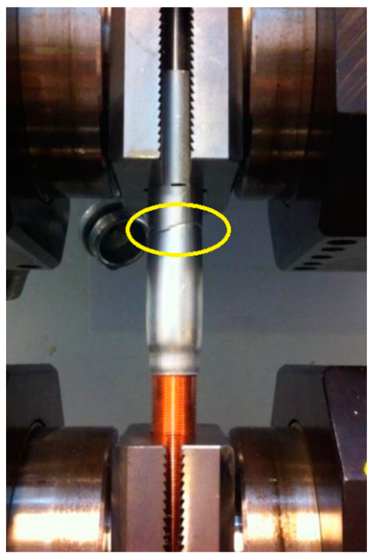
Table 8 presents the load values registered at the failure points of the welds, performed in this study, obtained from uniaxial tensile tests. All joints failed in the welded zones except for the specimen prepared by threading (Al/Cu-R), in this specimen failure occurred at the Al tube base as illustrated in Figure 6. It means that the resistance of the Al/Cu-R joint was superior to the base material though there was not any metallurgical bonding. The occurrence of a failure in the base material is an indication of a sound joint.
The smallest tensile load registered in this study belongs to the joint produced by the use of lubricated specimen (Al/Cu-O), this weak bonding is attributed to the lack of welding due to the excess of contamination and poor efficiency of the jet phenomenon. Nonetheless, the joint produced by the use of threaded target (Al/Cu-R) showed the highest load at the failure point. This achievement is attributed to the occurrence of the crimping joint rather than welding (Figure 4f and Figure 5f). Regarding the load values, Table 8 also depicts that the Al/Cu-Q joint follows the Al/Cu-R, the microstructure of the joint interface (Figure 4d and Figure 5d) contributed to this level of load, and the waviness pattern, which is a strong characteristic of MPW process, was more pronounced in the Al/Cu-Q joint.
In fact, the impact of surface roughness has been influenced by the welding windows. However, a moderate roughness and a perfectly clean surface are required, which is consistent with similar studies [19].
4. Conclusions
A high velocity plastic deformation joining technique was performed on dissimilar Al/Cu tubular assemblies through the application of magnetic pulse forces. This study evaluated the influence of the surface roughness of the copper target component on the quality of the joint considering the microstructure of the interface and the fracture load obtained from the uniaxial tensile test.
The surface condition of the target component influences the welding quality. However, it is not possible to correlate the surface roughness of the target with the waviness interface and also with the tensile load. Nonetheless, the formation of a waviness pattern at the joint interface requires a moderate roughness since neither the smoothest surface (polished copper) nor the least smooth surface (sandblasted surface) established a waviness pattern, and the best pattern was formed in the joint produced by the use of chemically treated surface. The surface roughness should have influenced the jet formation and consequently the pattern at the joint interface. Though the MPW is called a solid-state process, the occurrence of localized melting was verified. The formation of the intermetallic compounds (mainly Al2Cu phase) at the Al/Cu joint interfaces which found wavy patterns is confirmed. Moreover, some microvoids and a few microcracks were also formed in these reacted zones.
The strongest joint was obtained from the use of a threaded target, and it was achieved without the formation of any intermetallic or waviness at the interface. This joint failed at the Al tube base during the tensile test, indicating a sound joint though it was not a metallurgical type. Thus, in the MPW process, it seems very challenging to achieve an effective metallurgical bond.
The joint assembly prepared by lubrication on the target surface failed during the MPW process, meaning that the preparation of a clean surface appears a prerequisite for this process.
For this study, the parameters such as the standoff distance, the voltage level, and LWZ distance were kept constant, and this arrangement was implemented to study the influence of the surface conditions for the same working conditions. However, it seems that the samples’ length may influence joint formation. Thus, for any design, a new welding window should be optimized.
Author Contributions
Contributed to the conceptualization of this study, A.R., I.V.d.O., and G.A.T.; contributed to the experiments, A.M.R.; contributed to the conceptualization and writing the manuscript, O.E.; provided the revision, O.E. and A.R. All authors have read and agreed to the published version of the manuscript.
Funding
This research received no external funding.
Conflicts of Interest
The authors declare no conflict of interest.
References
- Properties and Selection: Nonferrous Alloys and Special Purpose Materials, 10th ed.; ASM International: Almere, The Netherlands, 1990; Volume 2.
- Kah, P.; Vimalraj, C.; Martikainen, J.; Suoranta, R. Factors influencing Al-Cu weld properties by intermetallic compound formation. Int. J. Mech. Mater. Eng. 2015, 10, 10. [Google Scholar] [CrossRef] [Green Version]
- Mori, K.I.; Bay, N.; Fratini, L.; Micari, F.; Tekkaya, A.E. Joining by plastic deformation. CIRP Ann.-Manuf. Technol. 2013, 62, 673–694. [Google Scholar] [CrossRef]
- Wang, H.; Wang, Y. High-velocity impact welding process: A review. Metals 2019, 9, 144. [Google Scholar] [CrossRef] [Green Version]
- Kang, B.-Y. Review of magnetic pulse welding. J. Weld. Join. 2015, 33, 7–13. [Google Scholar] [CrossRef] [Green Version]
- Psyk, V.; Risch, D.; Kinsey, B.L.; Tekkaya, A.E.; Kleiner, M. Electromagnetic forming—A review. J. Mater. Process. Technol. 2011, 211, 787–829. [Google Scholar] [CrossRef]
- Cai, W.; Daehn, G.; Vivek, A.; Li, J.; Khan, H.; Mishra, R.S.; Komarasamy, M. A state-of-the-art review on solid-state metal joining. J. Manuf. Sci. Eng. 2019, 141, 031012. [Google Scholar] [CrossRef]
- Watanabe, M.; Kumai, S. High-speed deformation and collision behavior of pure aluminum plates in magnetic pulse welding. Mater. Trans. 2009, 0906290826. [Google Scholar] [CrossRef] [Green Version]
- Kapil, A.; Sharma, A. Magnetic pulse welding: An efficient and environmentally friendly multi-material joining technique. J. Clean. Prod. 2015, 100, 35–58. [Google Scholar] [CrossRef]
- Ben-Artzy, A.; Stern, A.; Frage, N.; Shribman, V.; Sadot, O. Wave formation mechanism in magnetic pulse welding. Int. J. Impact Eng. 2010, 37, 397–404. [Google Scholar] [CrossRef]
- Stern, A.; Shribman, V.; Ben-Artzy, A.; Aizenshtein, M. Interface phenomena and bonding mechanism in magnetic pulse welding. J. Mater. Eng. Perform. 2014, 23, 3449–3458. [Google Scholar] [CrossRef]
- Wu, X.; Shang, J. An investigation of magnetic pulse welding of Al/Cu and interface characterization. J. Manuf. Sci. Eng. 2014, 136, 051002. [Google Scholar] [CrossRef]
- Rebensdorf, A.; Boehm, S. Increase of the reproducibility of joints welded with magnetic pulse technology using graded surface topographies. In Proceedings of the 7th International Conference on High Speed Forming, Dortmund, Germany, 27–28 April 2016; pp. 125–136. [Google Scholar]
- Cui, J.; Sun, T.; Geng, H.; Yuan, W.; Li, G.; Zhang, X. Effect of surface treatment on the mechanical properties and microstructures of Al-Fe single-lap joint by magnetic pulse welding. Int. J. Adv. Manuf. Technol. 2018, 98, 1081–1092. [Google Scholar] [CrossRef]
- Rebensdorf, A.; Böhm, S. Magnetic pulse welding—Investigation on the welding of high-strength aluminum alloys and steels as well as the influence of fluctuations in the production on the welding results for thin metal sheets. Weld. World 2018, 62, 855–868. [Google Scholar] [CrossRef]
- Lee, W.-B.; Bang, K.-S.; Jung, S.-B. Effects of intermetallic compound on the electrical and mechanical properties of friction welded Cu/Al bimetallic joints during annealing. J. Alloy. Compd. 2005, 390, 212–219. [Google Scholar] [CrossRef]
- Oliveira, I.; Cavaleiro, A.; Taber, G.; Reis, A. Magnetic Pulse Welding of Dissimilar Materials: Aluminum-Copper. In Materials Design and Applications; Silva, L.F.M.d., Ed.; Springer: Berlin/Heidelberg, Germany, 2017; pp. 419–431. [Google Scholar] [CrossRef]
- Inês Vieira de Oliveira, I.V. Pulse Technology as a Tool for Multi-Material Joining; Faculty of Engineering University of Porto: Porto, Portugal, 2016. [Google Scholar]
- Marre, M.; Weddeling, C.; Hammers, T.; Merzkirch, M.; Rautenberg, J.; Tekkaya, A.; Schulze, V.; Biermann, D.; Zabel, A. Innovative joining methods in lightweight designs, Part II. Alum. Int. J. Ind. Res. Appl. 2010, 86, 55–59. [Google Scholar]
Figure 1.
The setup applied for the performance of MPW in this study: (a) the coil assembly (A) on the station of the equipment, (b) the arrangement of coil-flyer-target (that were kept constant in this study).
Figure 1.
The setup applied for the performance of MPW in this study: (a) the coil assembly (A) on the station of the equipment, (b) the arrangement of coil-flyer-target (that were kept constant in this study).

Figure 2.
The processing window applied for welding in this study (adapted from [18]).
Figure 2.
The processing window applied for welding in this study (adapted from [18]).

Figure 3.
(a) The placement of the welded specimen between the grips of the tensile test, (b) the grips used for holding samples (a SOLIDWorks® design).
Figure 3.
(a) The placement of the welded specimen between the grips of the tensile test, (b) the grips used for holding samples (a SOLIDWorks® design).

Figure 4.
SEM/BSE images from the (a) Al/Cu-M, (b) Al/Cu-G, (c) Al/Cu-P, (d) Al/Cu-Q, (e) Al/Cu-O, and (f) Al/Cu-R joints produced by MPW technique.
Figure 4.
SEM/BSE images from the (a) Al/Cu-M, (b) Al/Cu-G, (c) Al/Cu-P, (d) Al/Cu-Q, (e) Al/Cu-O, and (f) Al/Cu-R joints produced by MPW technique.


Figure 5.
SEM/BSE images used for the chemical analysis of the interested zones at the interfaces of the (a) Al/Cu-M, (b) Al/Cu-G, (c) Al/Cu-P, (d) Al/Cu-Q, (e) Al/Cu-O, and (f) Al/Cu-R joints produced by MPW technique.
Figure 5.
SEM/BSE images used for the chemical analysis of the interested zones at the interfaces of the (a) Al/Cu-M, (b) Al/Cu-G, (c) Al/Cu-P, (d) Al/Cu-Q, (e) Al/Cu-O, and (f) Al/Cu-R joints produced by MPW technique.


Figure 6.
The Al/Cu-R tensile specimen illustrating the fractured zone (seen in yellow insert).


Table 1.
A summary of related studies on the influence of surface preparation for MPW process.
| Materials | Preparation Conditions | Results | Ref. |
|---|---|---|---|
| AA6063-O Al (flyer) to C110 Cu (target) tubes | A: tangential scratches over Cu length made by lathe B: axial scratches along the Cu length by 200-grit C: A + silicon-based high-viscosity lubricant oil | A: was in favour C: failed | [12] |
| EN AW-1050 Al (flyer) to S235 JR steel (target) sheets | Belt grinding Laser ablation | Not clearly explained | [13] |
| Al5182 (flyer) to HC340LA steel | Grinding steel parallel to welding (PW) Grinding steel vertical to welding (VW) | VW caused a wavy-shape interface and better mechanical properties PW caused straight interface with less elemental diffusion | [14] |
| EN AW-6016-T6 Al (flyer) to DC04 steel (target) sheets | Untreated surface Polished surface Laser ablation | Surface pre-treatment was not essential Processing window was the most important factor | [15] |
Table 2.
Physical and mechanical properties of the Al flyer and of the Cu target used in this study.
Table 2.
Physical and mechanical properties of the Al flyer and of the Cu target used in this study.
| Material | Density (kg/m3) | Youg‘s Modulus (GPa) | Yield Strength (MPa) | Shear Modulus (GPa) | Tensile Strength (MPa) | Hardness (HV) | Fracture Toughness (MPa m) | Melting Point (°C) | Electrical Resistivity (μΩcm) |
|---|---|---|---|---|---|---|---|---|---|
| Cu-R300 | 8940–8950 | 127 | 250 | 45–50 | 290–360 | 90–110 | 43.2–57.6 | 1083 | 1.70–1.74 |
| AA 6063-T5 | 2660–2710 | 67.2–70.7 | 113–125 | 25.3–26.6 | 158–175 | 61.8–68.3 | 30–36 | 615–655 | 3.08–3.21 |
Table 3.
Roughness measurements of the copper R300 rods.
| Sample Indication | M | G | P | Q |
|---|---|---|---|---|
| Ra (µm) | 1.5 | 4.8 | 0.6 | 2.1 |
| Rq (µm) | 1.9 | 6.1 | 0.7 | 2.5 |
Table 4.
Welding parameters applied in this study that were kept constant [17].
Table 4.
Welding parameters applied in this study that were kept constant [17].
| Energy [kJ] | Voltage [kV] | LWZ [mm] | Air Gap [mm] |
|---|---|---|---|
| 10.24 | 16 | 8 | 1 |
Table 5.
Tensile tests parameters according to ASTM A 370.
| Cell | Type of Grip | Test Speed |
|---|---|---|
| 200 kN | Hydraulic | 2 mm/min |
Table 6.
The average thickness (in μm) of intermetallic layers formed at the interface of the joints obtained in this study.
Table 6.
The average thickness (in μm) of intermetallic layers formed at the interface of the joints obtained in this study.
| Joint | Aluminium Side | Copper Side |
|---|---|---|
| Al/Cu-M | 0 to 12 ± 8 | 23 ± 22 |
| Al/Cu-G | 17 ± 15 | 27 ± 15 |
| Al/Cu-P | 0 to 13 ± 7 | 11 ± 7 |
| Al/Cu-Q | 0 to 30 ± 13 | 18 ± 15 |
Table 7.
The SEM/EDS results obtained from the zones of interest indicated in the images in Figure 5.
Table 7.
The SEM/EDS results obtained from the zones of interest indicated in the images in Figure 5.
| Zone | Al (at.%) | Cu (at.%) | Others (at.%) | Probable Coumpound |
|---|---|---|---|---|
| Z1 | 63 | 37 | - | θ |
| Z2 | 72 | 28 | - | θ |
| Z3 | 62 | 38 | - | θ |
| Z4 | 70 | 30 | - | θ |
| Z5 | 66 | 34 | - | θ |
| Z6 | 65 | 35 | - | θ |
| Z7 | 67 | 33 | - | θ |
| Z8 | 2.8 | 1.0 | 19.3 O2, 76.4 C, 0.5 S | - |
| Z9 | 1.5 | 26.3 | 5.6 O2, 66.6 C | - |
| Z10 | 93 | 7 O2 | - | |
| Z11 | 68 | - | 25 C, 7 O2 | - |
| Z12 | - | 88 | 10 C, 2 O2 | - |
Table 8.
The result of the tensile test performed for the joints.
| Joint | Al/Cu-M | Al/Cu-G | Al/Cu-P | Al/Cu-Q | Al/Cu-O | Al/Cu-R |
|---|---|---|---|---|---|---|
| Load at fracture (kN) | 12.1 | 12.1 | 13.1 | 14.3 | 9.6 | 19.7 |
© 2020 by the authors. Licensee MDPI, Basel, Switzerland. This article is an open access article distributed under the terms and conditions of the Creative Commons Attribution (CC BY) license (http://creativecommons.org/licenses/by/4.0/).
Share and Cite
MDPI and ACS Style
Emadinia, O.; Ramalho, A.M.; de Oliveira, I.V.; Taber, G.A.; Reis, A. Influence of Surface Preparation on the Interface of Al-Cu Joints Produced by Magnetic Pulse Welding. Metals 2020, 10, 997. https://doi.org/10.3390/met10080997
AMA Style
Emadinia O, Ramalho AM, de Oliveira IV, Taber GA, Reis A. Influence of Surface Preparation on the Interface of Al-Cu Joints Produced by Magnetic Pulse Welding. Metals. 2020; 10(8):997. https://doi.org/10.3390/met10080997
Chicago/Turabian StyleEmadinia, Omid, Alexandra Martins Ramalho, Inês Vieira de Oliveira, Geoffrey A. Taber, and Ana Reis. 2020. "Influence of Surface Preparation on the Interface of Al-Cu Joints Produced by Magnetic Pulse Welding" Metals 10, no. 8: 997. https://doi.org/10.3390/met10080997
Note that from the first issue of 2016, this journal uses article numbers instead of page numbers. See further details here.