Laser Welding of ASTM A553-1 (9% Nickel Steel) (PART II: Comparison of Mechanical Properties with FCAW)

Smart Mobility Materials and Components R&D Group, Korea Institute of Industrial Technology, Gwangju 61012, Korea
*
Author to whom correspondence should be addressed.
Metals 2020, 10(8), 999; https://doi.org/10.3390/met10080999
Submission received: 12 July 2020
/
Revised: 19 July 2020
/
Accepted: 20 July 2020
/
Published: 24 July 2020
Abstract
:The International Maritime Organization (IMO) is tightening regulations to reduce greenhouse gas emissions from ship operations. As a result, the number of vessels using liquefied natural gas (LNG) as fuel has increased rapidly. At this time, ASTM A553-1 (9% nickel steel) is being used as a tank material for storing LNG as fuel because of its higher strength than other cryogenic materials. Currently, shipyards are manufacturing LNG fuel tanks using the flux cored arc welding (FCAW) method using 9% nickel steel material. However, fabrication through FCAW has two drawbacks. The first is that the welding filler is 20 times higher cost than the base metal, and the second is that the total production cost increases because the thickness of the tank increases due to the strength drop near the heat affected zone (HAZ) after welding. The laser welding of A553-1, which does not require additional welding fillers and has no yield and tensile strength reduction in the HAZ, can overcome the drawbacks of FCAW and ensure price competitiveness. Through the study of Part I (penetration shape by bead on plate), the penetration characteristics of laser welding were studied and the optimized welding conditions of 15 mm thickness of A553-1 were obtained. With optimized conditions, butt laser welding tests of A553-1 material were conducted in this study, and mechanical properties, which are tensile/yield strength, hardness, bending strength, and impact property on the cryogenic temperature of the weld zone after laser beam welding, are confirmed by comparing those after FCAW. In the case of tensile/yield strength, hardness, and bending strength at weldment, the values of laser beam welding (LBW) are higher than those of FCAW, and the value of the impact test after FCAW is higher than that of LBW, but both values are satisfied in ASTM. Through these conclusions, it is confirmed that there are no mechanical property problems in replacing the existing FCAW with LBW.
1. Introduction
Recently, the shipbuilding industry has been moving rapidly in response to environmental issues. The International Maritime Organization (IMO) is tightening regulations to reduce greenhouse gas emissions from ship operations. By using liquefied natural gas (LNG) as fuel, CO2 emission is reduced by about 20%, nitrogen oxides (NOx) by 80%, sulfur oxides (SOx) by 90%, and particulate matter (PM) by 99% compared to when using heavy fuel oil (HFO), which is the existing marine fuel, and it is possible to satisfy the standards of Tier III [1,2,3,4]. In order to cope with such environmental regulations, major shipbuilding companies in the world have been developing LNG fuel propulsion ships, and the need for fuel tanks for storing and transporting fuel at cryogenic temperature is increasing. In addition, the fuel tank for storing and transporting cryogenic fuel is produced through the cryogenic material list in IGC (International Code for the Construction & Equipment of Ships Carrying Liquefied Gases in Bulk), which is A553-1, stainless steel 304 L, aluminum alloy 5083-0, and invar [5].
A553-1 is used as a material for cryogenic tanks such as LNG and has recently been used as an LNG fuel tank material because of its relatively higher yield strength/tensile strength than other materials [6]. There are several factors that determine the thickness of LNG fuel tanks, among which the minimum yield/tensile strength is an important factor. The material of A553-1 has a weak point in that the thickness of the tank becomes thicker due to weakened strength at the weld after welding because of the lower mechanical properties of the filler metal, which is ENIMo13T0-1 (1.2 mm), mostly used in recent projects of shipyards [7].
Laser welding has been studied for application to various materials due to its low welding deformation, easy automation, and its characteristics of heat affected parts [8,9,10,11]. Laser welding, which does not require additional welding fillers, can overcome the drawbacks of flux cored arc welding (FCAW), widely used because of its welding efficiency and easy weldability, and ensure price competitiveness in the case of A553-1 welding [12,13,14].
From the study of Part I (penetration shape by bead on plate), the penetration characteristics of laser beam welding (LBW) according to the welding speed and power are studied. The results of this study can be summarized as follows.
(1) The increase in bead height and bead width of 9% nickel steel was not uniform as the laser power increased. However, the penetration depth of the two materials was highly dependent on the laser power, despite the difference in properties of the two materials. In the case of A553-1, when the welding power increased from 3 to 5 kW, the average penetration depth increased from 4.3 to 5.7 mm.
(2) In the case of the laser welding of A553-1, as the welding speed increased, the bead height, width, and penetration depth were reduced. To prevent weld under-fill, welding must ultimately be performed at a speed equal to or less than the constant speed. It was confirmed that the occurrence of under-fill was dependent on the welding speed, and the results were observed in a specific range (over 1.5 m/min).
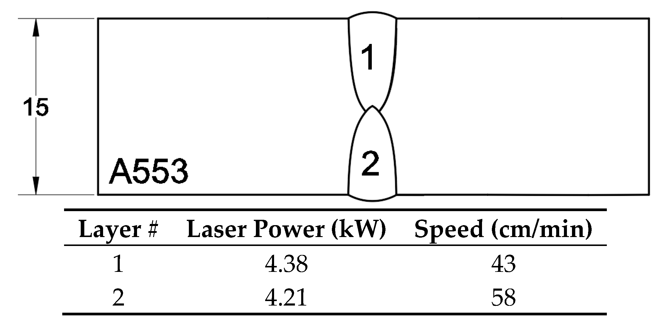
Based on the results of the Part I study, an optimized 2-pass laser butt welding condition of 15 mm thickness of A553-1, predicted to be most used in LNG fuel propulsion tanks, was obtained. This is the condition that maintains the long and narrow penetration during welding of 15 mm thick A553-1 by laser butt welding and can be fully penetrated. The laser welding conditions used are a 2-pass welding condition with a penetration depth of 8 mm (1st pass) and 7 mm (2nd pass) from Part I as shown in Figure 1. In the case of LBW, a no-filler metal with a 0 mm gap between base materials is required, and the experiment is performed using autogenous 1G welding. Shielding gas of 99.99% Ar (18 L/min) is used on the top (face side) of the base material and defocus value is 0 mm.
The purpose of this study is the comparison of mechanical properties (tensile/yield strength, hardness, bending strength, and impact property on cryogenic temperature) of the weld zone between LBW and FCAW.
2. Experiment Conditions of FCAW and LBW
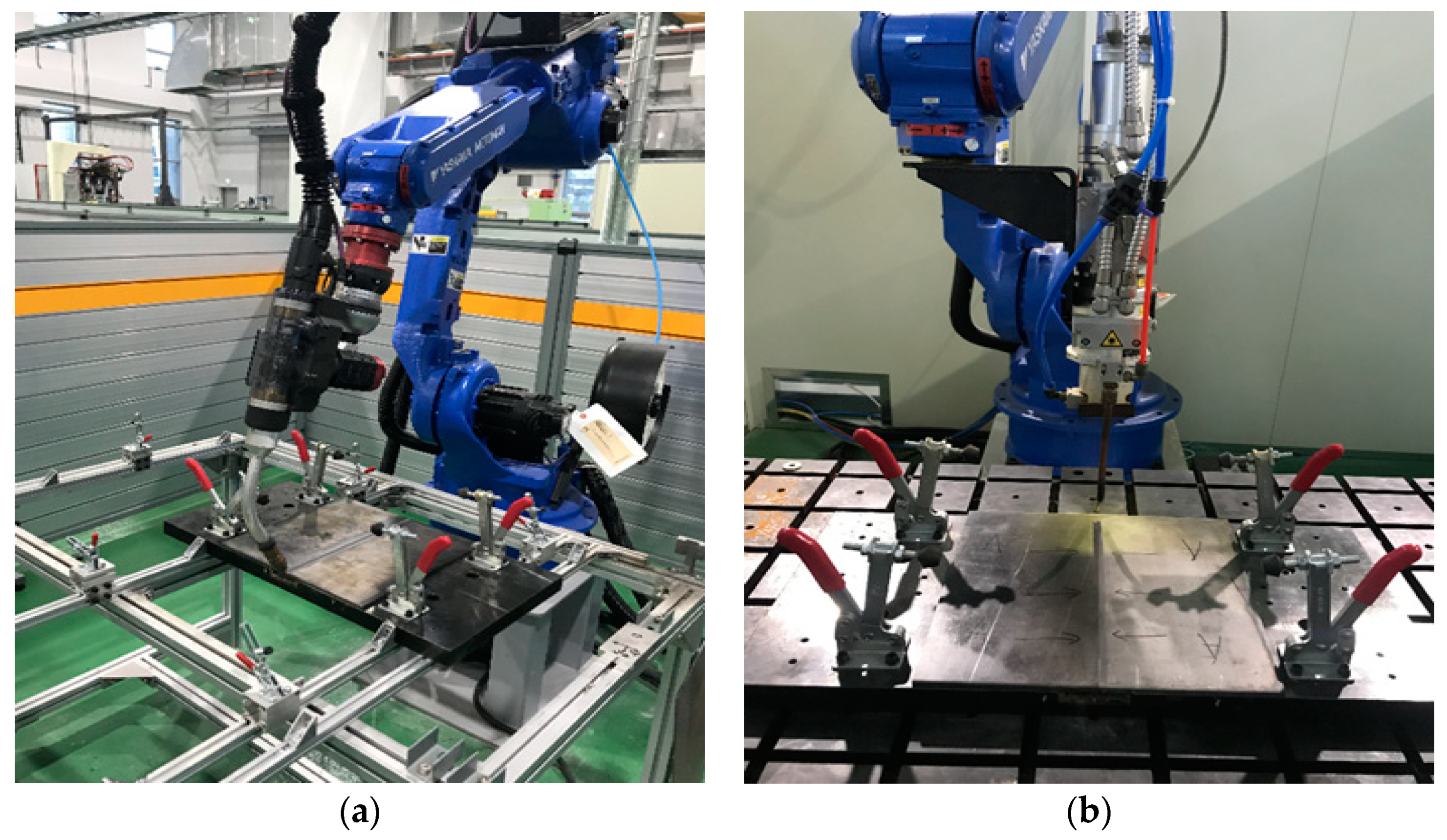
The welding equipment used in this study were both a 500 A current FCAW from SKS, Germany and a 5 kW fiber LBW from Miyachi, Japan. The 6-axis robot system was used for both FCAW and LBW. Figure 2 shows the welding equipment used in the experiment.
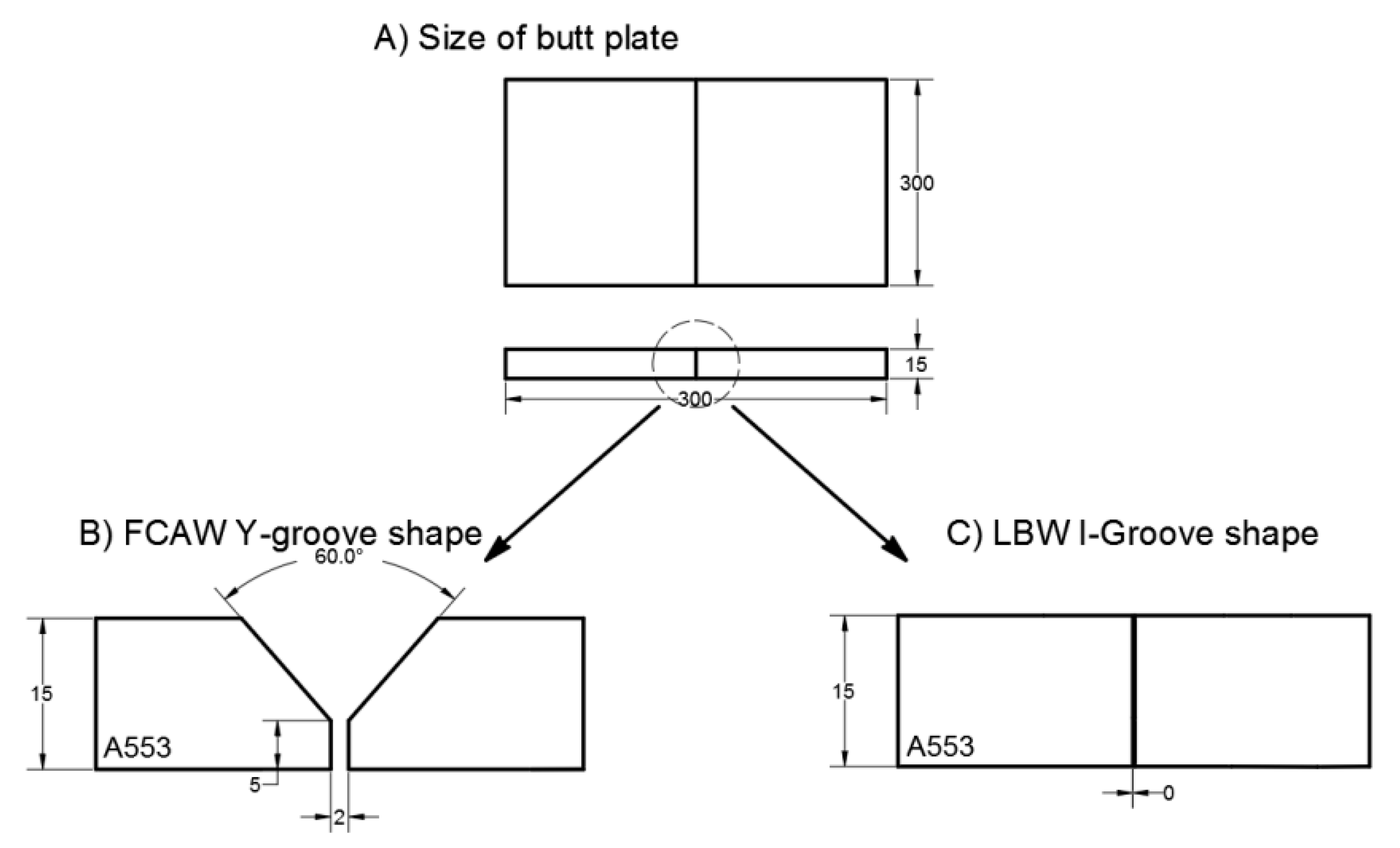
The dimensions of the welding material used in the experiment were 300 mm × 300 mm × 15 mm. The specimens were machined into Y-grooves for FCAW and I-grooves for LBW as shown in Figure 3.
The FCAW experiments were conducted based on the welding procedure specification (WPS) of the filler metal, which is ENIMo13T0-1 (1.2 mm) designated AWS A5.34 and provided by Kobe. The chemical composition of the filler is shown in Table 1.
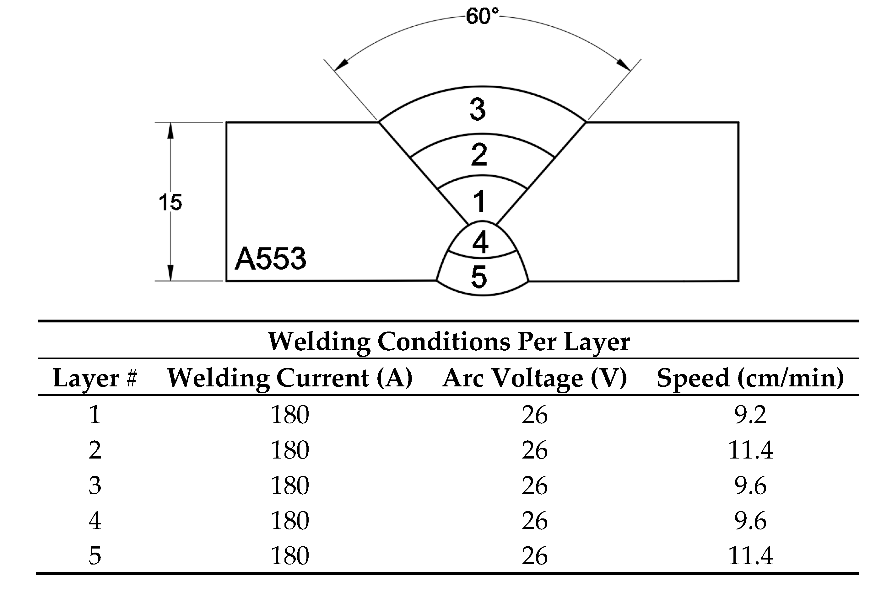
The FCAW experiments were carried out in a condition of 1 G position and 80% Ar-20% CO2 (18 L/min) as shielding gas, and the contact tip-work distance was 15 mm, referred to the technical report by the filler maker. The welding layer consisted of a 5-pass, which is a 3-pass at the top of the material and a 2-pass at the bottom of the material after gouging. The welding conditions were as shown in Figure 4.
3. Mechanical Properties Comparison between FCAW and LBW
3.1. Yield and Tensile Strength
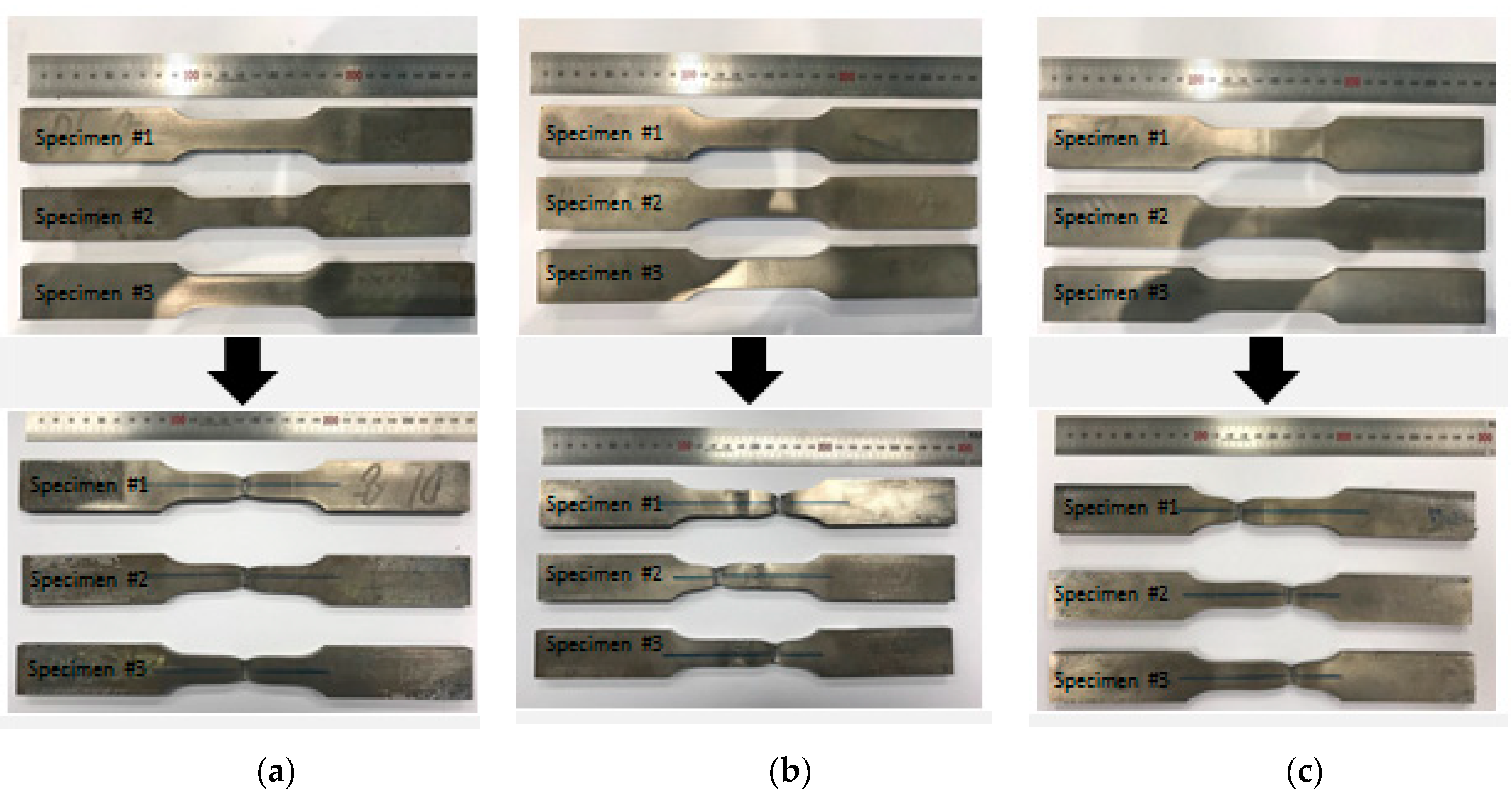
The yield and tensile strength tests of the welded zone were carried out using a universal tension machine (UTM). They are essential factors in designing the weldment of structures and are also a very important factor in the thickness determination of LNG fueled tanks [15,16,17]. The yield and tensile strength were evaluated by the ASME IX QW code and the test method is as specified in ASTM E8/E8M. The experimental setup accorded with the KDTM100 model with a mechanical load of up to 100 tons. The operation speed was related to the elongation. Because the purpose of this experiment was to compare the yield and tensile strengths of FCAW with those of LBW, each experiment was conducted three times. Figure 5 shows the tensile test specimens of three types, which are (a) base metal (A553-1), (b) FCAW, and (c) LBW, and the fracture position after the tensile test was performed.
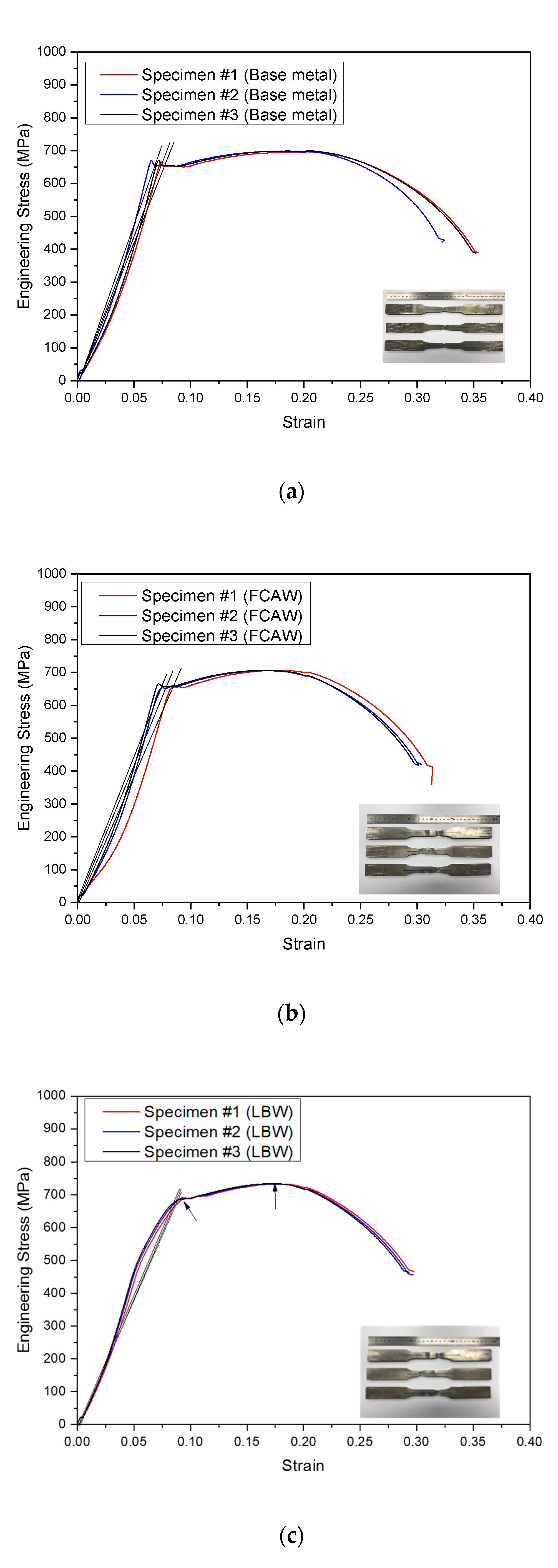
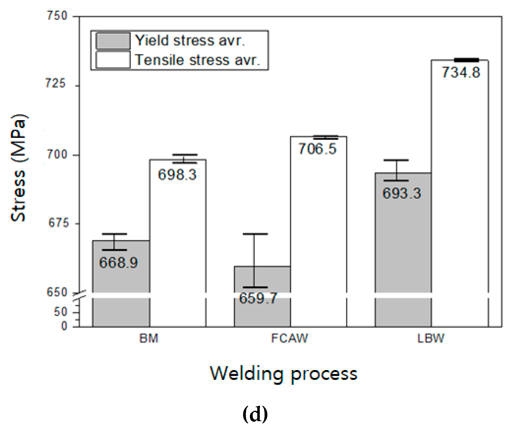
Figure 6a–c show the stress–strain curves by the welding process. Figure 6d shows the average values of each yield/tensile strength. In the results for (a), the yield strength and tensile strength of the base material were 668.9 MPa and 698.3 MPa. In the results for (b), the yield strength and tensile strength of the FCAW weldment were 659.7 MPa and 706.5 MPa. As the yield strength of the filler material was lower than the yield strength of the base material, it can be confirmed that the yield strength of the FCAW was slightly lower than the yield strength of the base material. In the results for (c), the yield strength and tensile strength of the LBW weldment were 693.3 MPa and 734.8 MPa. In the case of LBW, as no filler material was used, it can be confirmed that the value was higher than the yield strength and tensile strength of the base material.
3.2. Hardness Test
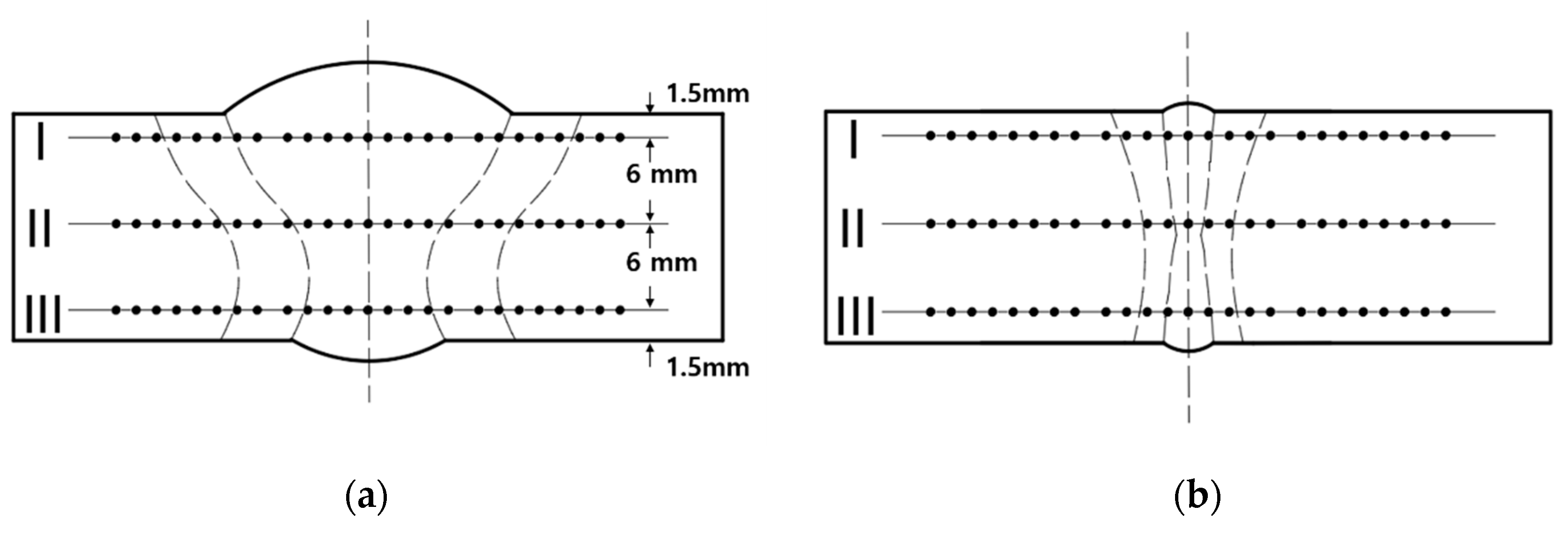
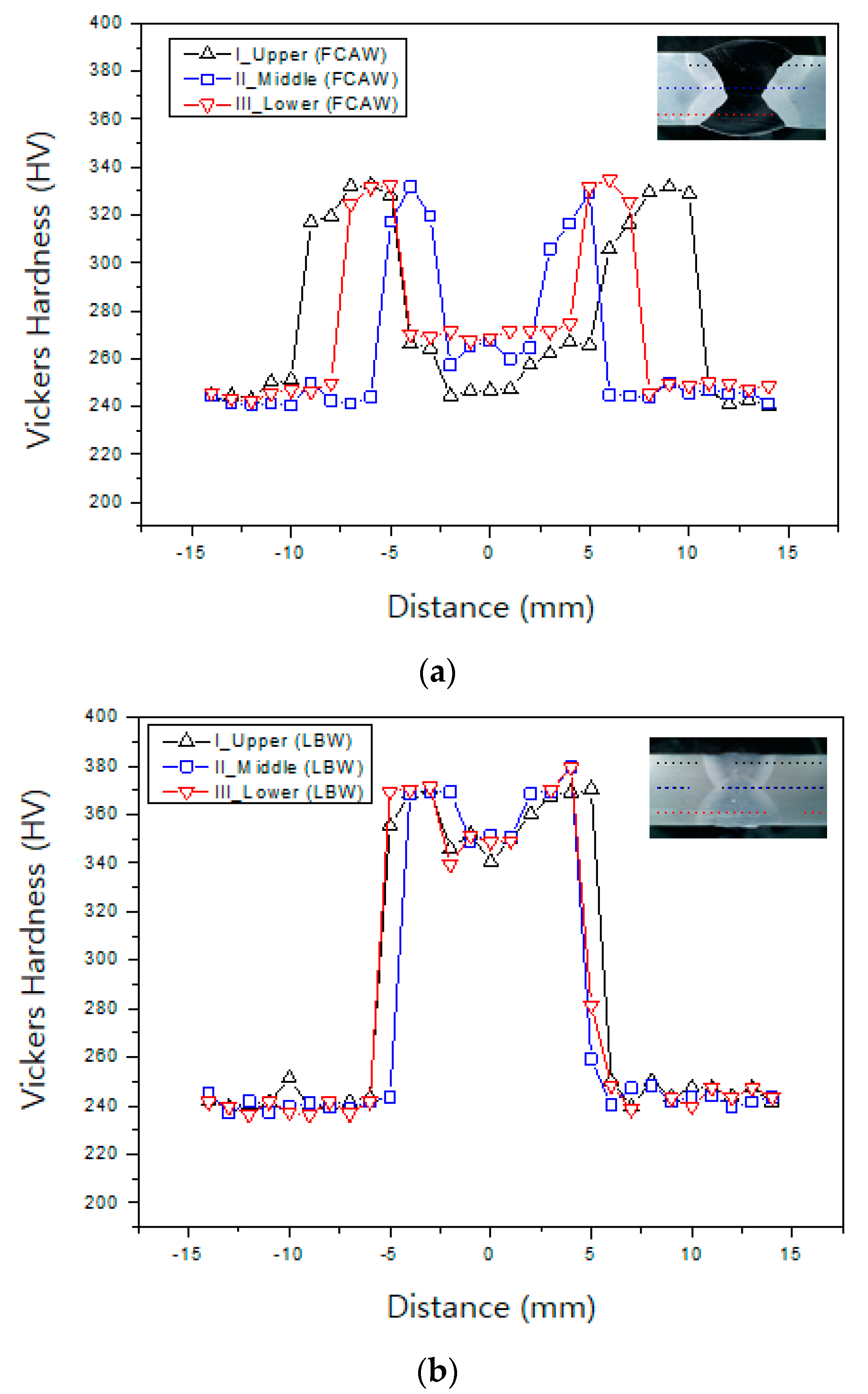
Hardness has a close relationship with other mechanical properties of materials such as tensile strength and fatigue strength. In this study, the welds are divided into upper, middle, and lower sections, as shown in Figure 7 below, to measure a total of 25 points at intervals of 0.5 mm. The hardness is measured with a Vickers hardness tester (Shimadzu, HMV-GT-21st) under the force of 0.50 HV (4.5 mN).
As a result of the hardness measurement of the weldment, the FCAW was improved from the heat affected zone (HAZ) to the maximum hardness of 334 HV as shown in Figure 8a, and the weld zone was measured at 20% higher than the base metal. In particular, hardness similar to that of the base material was observed at the upper part, and it was observed that the hardness of the base material was lower than that of other positions due to the continuous heat effect, which was influenced by the multi-pass. The hardness measurement results of LBW are shown in Figure 8b. The hardness of the weld zone and HAZ formed by laser welding showed a much higher hardness value (375 HV) than that of the base material, and the hardness value of the weld part was formed with an average of 350 HV.
3.3. Bending Test
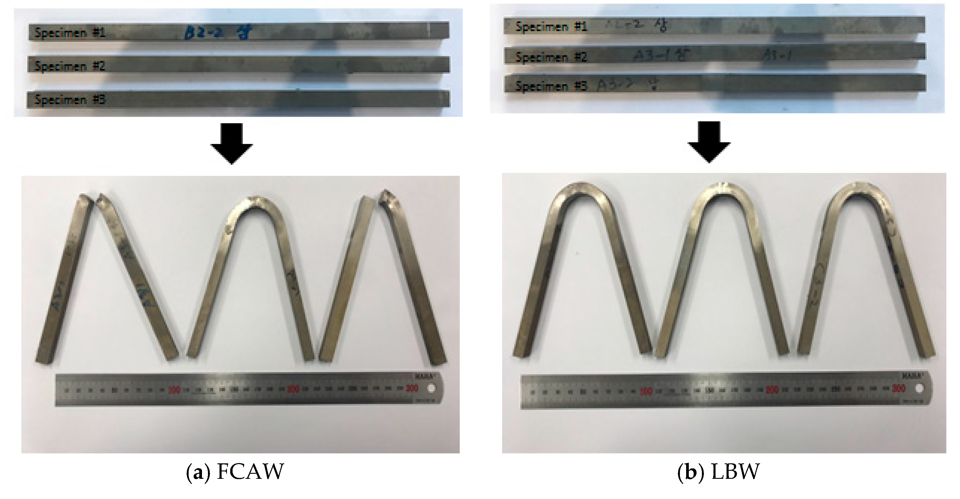
The bending test of the weld was carried out to confirm whether there was a harmful defect in the weld metal or whether it had sufficient ductility to the extent of the base metal. The common bending test used in this study is KS B 0804, which uses a U-jig called a 3-points bending test. The orientation of the specimen was made by bending the top, bottom, and side. The bending test of the butt weldment was based on the test method of KS B 0804. The bend test of the welded specimen and the results are shown in Figure 9.
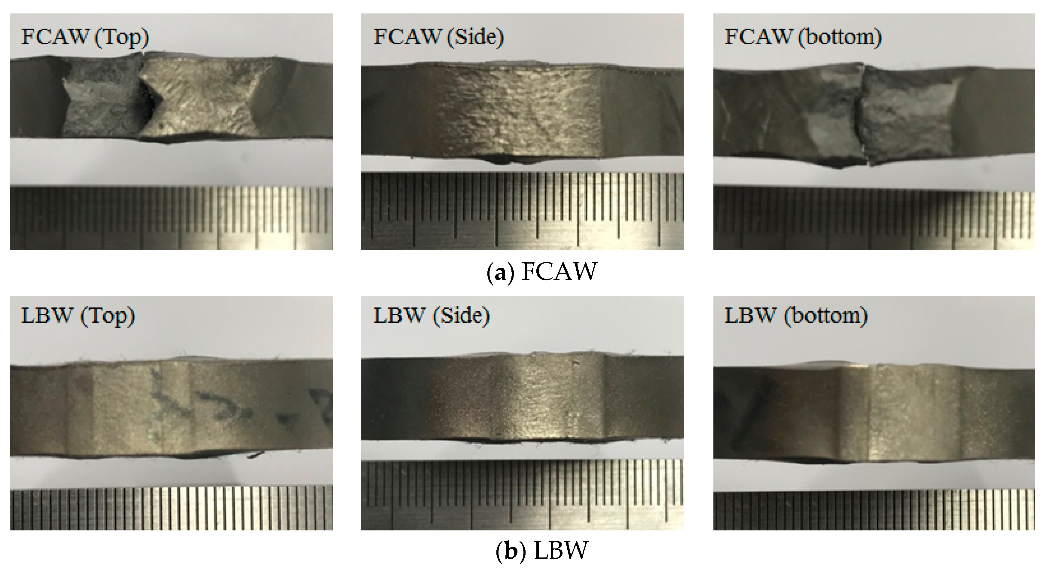
In the case of FCAW, fracture occurred at the upper part and the lower part. No break occurred at the upper, lower, and side parts of the LBW. The bending phenomenon of FCAW shows that the plastic deformation continuously occurred. Moreover, the fracture occurred at the interface between the welded part and the base metal, which was caused by the difference in physical properties between A553-1 and the filler metal. The filler metal has the disadvantage of a brittle dilution zone between weld and base metal, because it contains about 70% nickel and is resistant to low temperature. For this reason, breakage occurred at the interface between the weld zone and the base material as shown in Figure 10.
However, the plastic deformation in all directions of the LBW welds is less than those of FCAW. The autogenously welded LBW is considered to have high resistance to the bending moment without changing the bending characteristics of the base metal.
3.4. Impact Test at −196 °C
In the impact test, the specimen was instantaneously subjected to a load for 1 × 10⁻³ to 5 × 10⁻⁵ s to break it. The strengths of the material were judged by the magnitude of the energy (absorption energy) required for this rupture [18]. The test most widely used in industry is the impact test, in which an impact load is applied to a test piece with a notch. Generally, the material exhibiting a large plastic deformation during the tensile test, due to a high tensile strength, and sufficient ductility, due to a static load, absorbs the large impact energy against the impact failure and exhibits a high impact resistance and a high viscosity. On the other hand, a material lacking impact resistance exhibits brittleness due to its low impact-absorbing energy ability, even though its tensile strength is high.
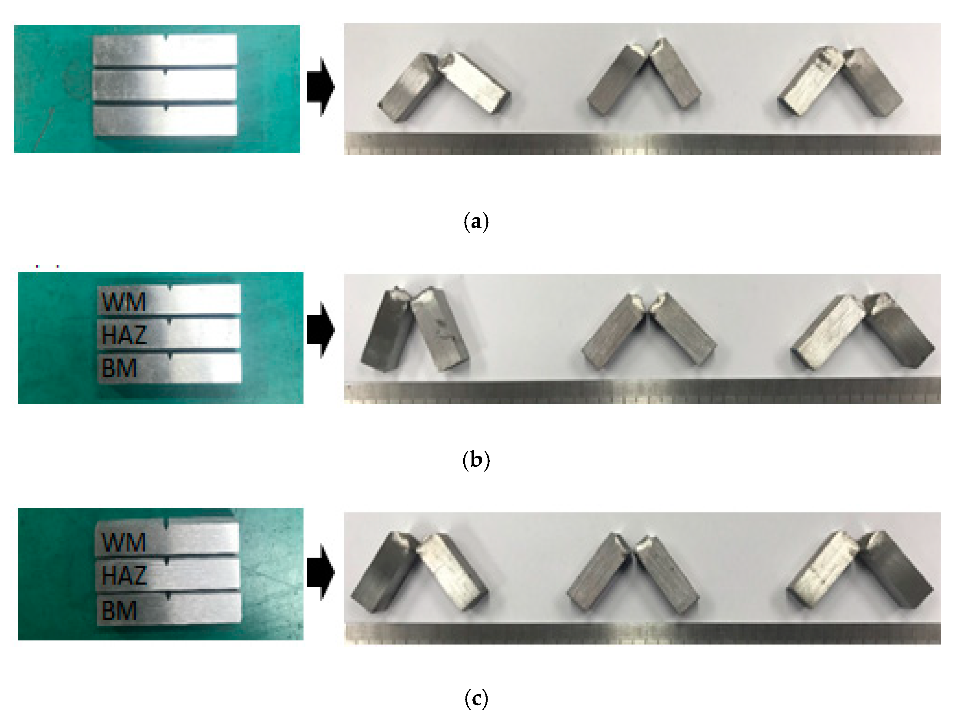
The impact test in this study was based on the method of cryogenic steel specified by IACS (International Association of Classification Societies) and the impact test method of ISO 21028-2: 2004 (en) (toughness requirements for materials at cryogenic temperature). The charpy impact tester, which has a maximum impact energy of 300 J, was used in this test. The impact absorption rate of cryogenic steel specified by IACS was at least 41 J. The experimental results were also evaluated by the provision that the cushion absorption rate of cryogenic steel in ATSM should be over 27 J [19]. In the impact test, liquid nitrogen was used to create a cryogenic environment, and a cryogenic impact test environment was established by immersing the specimen in liquid nitrogen for 5 min to quench the specimen. The experiment was performed three times. In addition, by measuring the impact absorption rate of the base material itself and comparing FCAW and LBW, the difference in shock absorption rate according to the welding process was observed. Figure 11 shows the prepared specimens and specimens after the impact test.
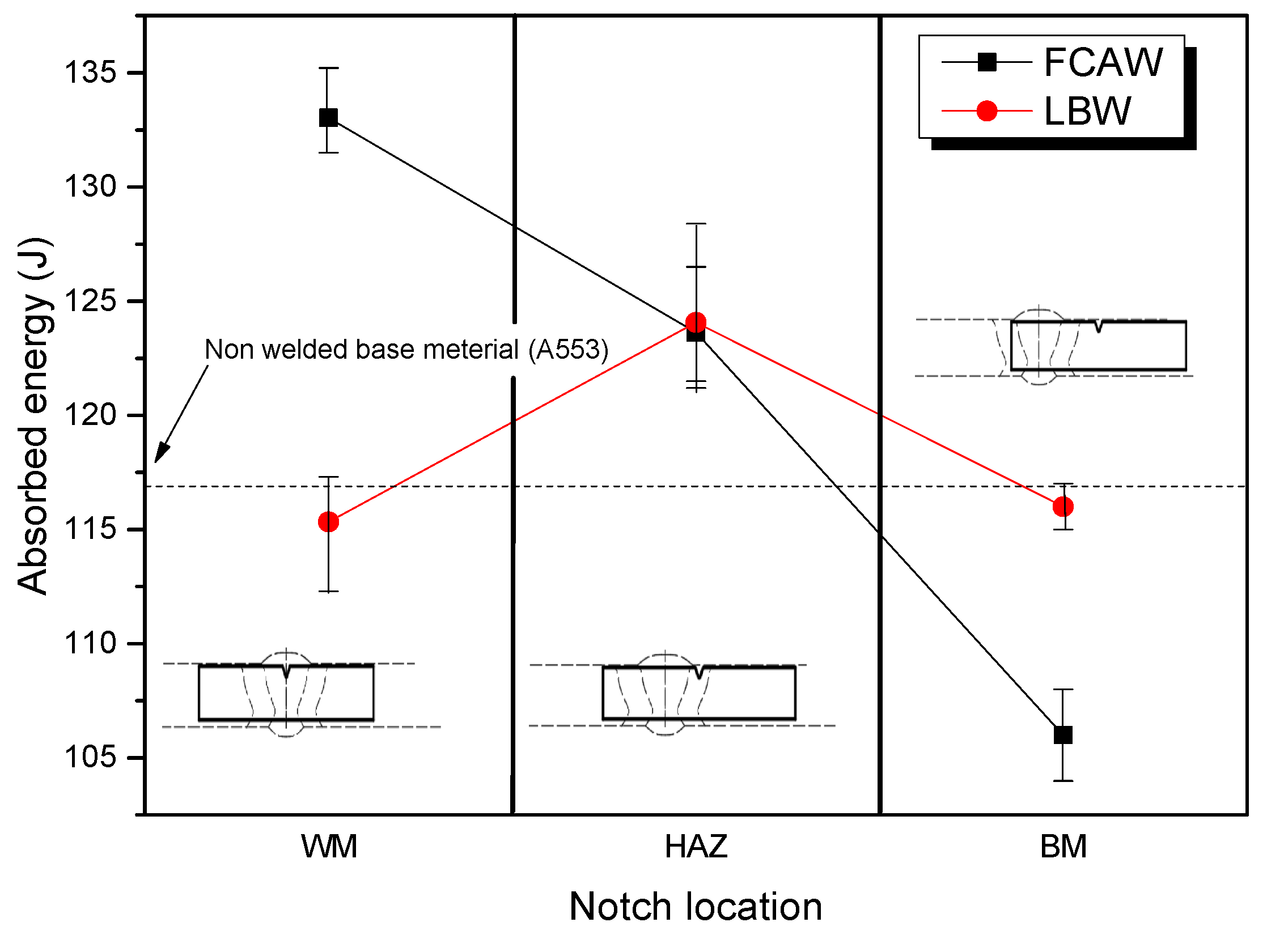
The impact-absorbed energy of the non-welded parent material was 117 J and is indicated by the dotted line in Figure 12. As mentioned above, the impact-absorbed energy of cryogenic steel was allowed to be 27 J in ASTM, which is a value that satisfies the standard. In addition, it meets the minimum impact-absorbed energy of cryogenic steel specified by IACS. The square dots represent the impact-absorbed energy of the LBW and the circle dots represent the impact-absorbed energy of the FCAW in Figure 12. The small horizontal bar shows the maximum and minimum shock absorption during three measurements, and the impact-absorbed energy of LBW was measured to be similar to the impact-absorbed energy of the base material. The impact-absorbed energy of the FCAW was measured by weld metal (WM) > HAZ > base metal (BM). The weld zone of the FCAW was a result of improved impact toughness of the weld zone due to the characteristics of the filler metal (containing 70% nickel). However, the impact-adsorbed energy of the base material (20 mm away from the weld zone) of the FCAW was 106 J, which is 10 J less than the impact-absorbed energy of the non-welded base material. It is not affected by the HAZ, but it can be predicted that the weld zone was softened because the heat temperature of less than 400 °C was applied to the base material.
4. Conclusions
In this study, the comparison of mechanical properties, which are tensile/yield strength, hardness, bending strength, and impact property on cryogenic temperature, of the weld zone between LBW and FCAW was performed.
(1) Yield strength and tensile strength: Both values of yield strength and tensile strength from the LBW weldment are higher than those of the FCAW weldment by about 5% and 4%, because LBW is performed with no filler material, which has the effect of reducing the microstructure during welding.
(2) Hardness: In the case of LBW, the maximum hardness value is 375 HV at the weld zone, and the maximum hardness value is 334 HV at the HAZ zone in the case of FCAW because of multi-pass, which affects the difference trends of hardness as shown in Figure 8.
(3) Bending strength: In the case of FCAW, a fracture occurs at the upper part and the lower part. No break occurs at the upper, lower, and side parts of the LBW. Because of the filler metal, the fracture occurs at the interface between the FCAW welded part and the base metal, which is caused by the difference in physical properties between A553-1 and the filler metal.
(4) Impact strength at cryogenic temperature: The impact strength value of FCAW is from 106 J (BM) to 134 J (WM) and LBW is from 115 J (WM) to 124 J (HAZ). The impact strength values of both FCAW and LBW satisfied ATSM at all positions, which are WM, HAZ, and BM as shown in Figure 12.
Author Contributions
Conceptualization: J.K. (Jaewoong Kim) and J.K. (Jisun Kim); methodology: J.K. (Jaewoong Kim); software: J.K. (Jisun Kim); validation: J.K. (Jaewoong Kim); formal analysis: J.K. (Jisun Kim); resources: J.K. (Jisun Kim); data curation: J.K. (Jisun Kim); writing—original draft preparation: J.K. (Jaewoong Kim); writing—review and editing: J.K. (Jaewoong Kim); visualization: J.K. (Jaewoong Kim); project administration: J.K. (Jaewoong Kim). All authors have read and agreed to the published version of the manuscript.
Funding
This research has been conducted with the support of the Ministry of Trade, Industry, and Energy, Republic of Korea as “Development of small and medium LNG fuel storage module for coastal ship” in the material parts technology development project.
Conflicts of Interest
The authors declare no conflict of interest.
References
- Kim, J.W.; Kim, J.S.; Kang, S.W.; Chun, K.S. Laser welding of ASTM A553-1 (9% Nickel Steel) (PART I: Penetration shape by bead on plate). Metals 2020, 10, 484. [Google Scholar] [CrossRef] [Green Version]
- Schinas, O.; Butler, M. Feasibility and commercial considerations of LNG-fueled ships. Ocean Eng. 2016, 122, 84–96. [Google Scholar] [CrossRef]
- Yoo, B.Y. Economic assessment of liquefied natural gas (LNG) as a marine fuel for CO2 carriers compared to marine gas oil (MGO). Energy 2017, 121, 772–780. [Google Scholar] [CrossRef]
- Thomson, H.; Corbett, J.J.; Winebrake, J.J. Natural gas as a marine fuel. Energy Policy 2015, 87, 153–167. [Google Scholar] [CrossRef] [Green Version]
- Kim, B.E.; Park, J.Y.; Lee, J.S.; Kim, M.H. Study on the initial design of an LNG fuel tank using 9 wt.% nickel steel for ships and performance evaluation of the welded joint. J. Weld. Join. 2019, 37, 555–563. [Google Scholar] [CrossRef] [Green Version]
- Lee, J.S.; You, W.H.; Yoo, C.H.; Kim, K.S.; Kim, Y.I. An experimental study on fatigue performance of cryogenic metallic materials for IMO type B tank. Int. J. Nav. Archit. Ocean 2013, 5, 580–597. [Google Scholar] [CrossRef] [Green Version]
- Na, K.B.; Lee, C.I.; Park, J.H.; Cho, S.M. A comparison of hot cracking in GTAW and FCAW by applying alloy 625 filler materials of 9% Ni steel. J. Weld. Join. 2019, 37, 357–362. [Google Scholar] [CrossRef] [Green Version]
- Kim, J.W.; Jang, B.S.; Kim, Y.T.; Chun, K.S. A study on an efficient prediction of welding deformation for T-joint laser welding of sandwich panel PART I: Proposal of a heat source model. Int. J. Nav. Archit. Ocean 2013, 5, 348–363. [Google Scholar] [CrossRef] [Green Version]
- Zhu, Y.; Li, C.; Zhang, L. Effects of cryo-treatment on corrosion behavior and mechanical properties of laser-welded commercial pure titanium. Mater. Trans. 2014, 55, 511–516. [Google Scholar] [CrossRef]
- Tsumura, T.; Murakami, T.; Nakajima, H.; Nakata, K. Numerical simulation of laser fusion zone profile of lotus-type porous metals. Mater. Trans. 2006, 47, 2248–2253. [Google Scholar] [CrossRef] [Green Version]
- Park, J.U.; Lee, J.B.; An, G.B.; Kim, S.M.; Seo, H.W. Characteristic of welding rotational deformation in laser welding of thin steel sheet. J. Weld. Join. 2018, 36, 1–7. [Google Scholar] [CrossRef] [Green Version]
- Swierczynska, A. Effect of storage conditions of rutile flux cored welding wires on properties of welds. Adv. Mater. Sci. 2019, 19, 46–56. [Google Scholar] [CrossRef] [Green Version]
- Mu, W.; Li, Y.; Cai, Y.; Wang, M.; Hua, X. The cryogenic low-cycle fatigue performance 9%Ni steel joint made by flux cored arc welding. Mater. Charact. 2019, 151, 27–37. [Google Scholar] [CrossRef]
- Rodrigues, L.A.S.; Loayza, L.C.R.; Borges, D.J.A.; Baia, P.E.C.; Freitas, E.N.; Braga, E.M. Welding procedures influence analysis on the residual stress distribution and distortion of stiffened panels welded via robotized FCAW. Thin-Walled Struct. 2019, 141, 175–183. [Google Scholar] [CrossRef]
- DNVGL Maritime. Rules for Classification—Part 5 Chapter 7 Liquefied Gas Tankers; DNV-GL: Oslo, Norway, 2019. [Google Scholar]
- Maritime, B.V. Rules for the Classification of Steel Ships—Pressure Equipment; Bureau Veritas (BV): Paris, France, 2019. [Google Scholar]
- Maritime Safety Committee. International Code of Safety for Ships Using Gases or Other Low-Flashpoint Fuels (IGF Code); International Maritime Organization (IMO): London, UK, 2016. [Google Scholar]
- ASTM International. ASTM E23: Standard Test Methods for Notched Bar, Impact Testing of Metallic Materials; American Society for Testing and Materials (ASTM): West Conshohocken, PA, USA, 2013. [Google Scholar]
- Kim, E.; Park, J.Y.; Lee, J.S.; Lee, J.I.; Kim, M.H. Effects of the welding process and consumables on the fracture behavior of 9 wt.% nickel steel. Exp. Tech. Sept. 2019, 44, 1–12. [Google Scholar] [CrossRef]
Figure 1.
Butt LBW conditions of A553-1 (15 mm thickness).

Figure 2.
Welding equipment. (a) FCAW equipment. (b) LBW equipment.

Figure 3.
Test specimens and groove shapes.

Figure 4.
Welding conditions of FCAW.

Figure 5.
Specimen after test for tensile strength each welding process. (a) Base metal (A553-1); (b) FCAW weldment; (c) LBW weldment.
Figure 5.
Specimen after test for tensile strength each welding process. (a) Base metal (A553-1); (b) FCAW weldment; (c) LBW weldment.

Figure 6.
Stress–strain curve and comparison of yield/tensile strength. (a) Stress–strain curve of base metal; (b) stress–strain curve of FCAW weldment; (c) stress–strain curve of LBW weldment; (d) comparison yield/tensile strength.
Figure 6.
Stress–strain curve and comparison of yield/tensile strength. (a) Stress–strain curve of base metal; (b) stress–strain curve of FCAW weldment; (c) stress–strain curve of LBW weldment; (d) comparison yield/tensile strength.


Figure 7.
Measurement points of hardness test. (a) FCAW; (b) LBW.

Figure 8.
Hardness curve at different upper, middle, and lower positions of FCAW specimen. (a) Hardness of FCAW; (b) hardness of LBW.
Figure 8.
Hardness curve at different upper, middle, and lower positions of FCAW specimen. (a) Hardness of FCAW; (b) hardness of LBW.

Figure 9.
The results of 3-points bending test.

Figure 10.
Comparison of bending test results. (a) 3-points bending specimen fracture shape with FCAW; (b) 3-points bending specimen fracture shape with LBW.
Figure 10.
Comparison of bending test results. (a) 3-points bending specimen fracture shape with FCAW; (b) 3-points bending specimen fracture shape with LBW.

Figure 11.
Prepared impact test specimens and tested specimens. (a) BM (Base metal). (b) FCAW. (c) LBW.
Figure 11.
Prepared impact test specimens and tested specimens. (a) BM (Base metal). (b) FCAW. (c) LBW.

Figure 12.
Comparison of LBW and FCAW impact-absorption energy by notch position.


Table 1.
The chemical composition of ENIMo13T0-1.
| Component | Percentage (%) |
|---|---|
| Carbon, C | 0.02 |
| Manganese, Mn | <0.01 |
| Phosphorous, P | <0.001 |
| Silicon, Si | <0.01 |
| Sulfur, S | <0.001 max |
| Nickel, Ni | 70.1 |
| Copper, Cu | <0.01 |
| Chromium, Cr | 1.9 |
| Molybdenum, Mo | 19.1 |
| Iron, Fe | 5.6 |
| Tungsten, W | 3.0 |
© 2020 by the authors. Licensee MDPI, Basel, Switzerland. This article is an open access article distributed under the terms and conditions of the Creative Commons Attribution (CC BY) license (http://creativecommons.org/licenses/by/4.0/).
Share and Cite
MDPI and ACS Style
Kim, J.; Kim, J. Laser Welding of ASTM A553-1 (9% Nickel Steel) (PART II: Comparison of Mechanical Properties with FCAW). Metals 2020, 10, 999. https://doi.org/10.3390/met10080999
AMA Style
Kim J, Kim J. Laser Welding of ASTM A553-1 (9% Nickel Steel) (PART II: Comparison of Mechanical Properties with FCAW). Metals. 2020; 10(8):999. https://doi.org/10.3390/met10080999
Chicago/Turabian StyleKim, Jaewoong, and Jisun Kim. 2020. "Laser Welding of ASTM A553-1 (9% Nickel Steel) (PART II: Comparison of Mechanical Properties with FCAW)" Metals 10, no. 8: 999. https://doi.org/10.3390/met10080999
Note that from the first issue of 2016, this journal uses article numbers instead of page numbers. See further details here.