Laser Metal Deposition of an AlCoCrFeNiTi0.5 High-Entropy Alloy Coating on a Ti6Al4V Substrate: Microstructure and Oxidation Behavior

1
Department of Mechanical and Aerospace Engineering, Missouri University of Science and Technology, Rolla, MO 65409, USA
2
Department of Mechanical Engineering, University of Texas at Dallas, Richardson, TX 75080, USA
3
Materials Research Center, Missouri University of Science and Technology, Rolla, MO 65409, USA
*
Author to whom correspondence should be addressed.
Crystals 2020, 10(8), 638; https://doi.org/10.3390/cryst10080638
Submission received: 15 June 2020
/
Revised: 17 July 2020
/
Accepted: 21 July 2020
/
Published: 23 July 2020
(This article belongs to the Special Issue Development of High Entropy Alloys)
Abstract
:Ti6Al4V has been recognized as an attractive material, due to its combination of low density and favorable mechanical properties. However, its insufficient oxidation resistance has limited the high-temperature application. In this work, an AlCoCrFeNiTi0.5 high-entropy alloy (HEA) coating was fabricated on a Ti6Al4V substrate using laser metal deposition (LMD). The microstructure and isothermal oxidation behaviors were investigated. The microstructure of as-deposited HEA exhibited a Fe, Cr-rich A2 phase and an Al, Ni, Ti-enriched B2 phase. Its hardness was approximately 2.1 times higher than that of the substrate. The oxidation testing at 700 °C and 800 °C suggested that the HEA coating has better oxidation resistance than the Ti6Al4V substrate. The oxide scales of the Ti6Al4V substrate were mainly composed of TiO2, while continuous Al2O3 and Cr2O3 were formed in the HEA coatings and could be attributed to oxidation resistance improvement. This work provides an approach to mitigate the oxidation resistance of Ti6Al4V and explore the applicability of the HEA in a high-temperature environment.
1. Introduction
Ti6Al4V has been an important and versatile titanium alloy currently used in petrochemical, automotive, power generation, and biomedical industries. Indeed, this alloy possesses a desirable combination of properties, such as high melting point, superior corrosion resistance, good biocompatibility, and weldability [1,2,3]. However, Ti6Al4V alloy is very active at elevated temperature, which results in being easily oxidized, as well as its insufficient oxidation resistance [4,5]. At present, the permitted maximal service temperature of Ti6Al4V alloy still does not exceed 600 °C [1,4]. The improvement of its high-temperature oxidation property can be solved by the surface modification process [3,4,5,6].
As a promising surface modification technology, laser metal deposition (LMD) has introduced a number of capabilities unparalleled by conventional process [3,6,7,8,9,10,11]. LMD achieves layer-by-layer fabrication of near net-shaped deposition onto the substrate by introducing a powder stream into a laser beam. In addition to the geometry freedom, precise tailoring of compositions and microstructure can be achieved to produce highly specialized coatings. On the basis of these advantages, many efforts have been made to improve the oxidation resistance of Ti6Al4V alloy. In particular, Liu et al. prepared a TiN/Ti3Al composite coating on the Ti6Al4V substrate [12]. The isothermal oxidation results indicated that the relative oxidation resistance of the coating was approximately six times higher than that of the substrate at 600 °C, due to the formation of TiN, Al2O3, and TiO2. A titanium–aluminum alloy (Ti48Al2Cr2Nb) was adopted as a coating material and demonstrated good anti-oxidation property in comparison with the Ti6Al4V at 800 °C [13]. Successive layers of oxides (up to 12 µm thick) were formed on the Ti48Al2Cr2Nb after 150 h of oxidation, while the oxide layers detached from the Ti6Al4V after 5 h. A gradient Ti-Ni alloy was fabricated by laser cladding, and a dense Al2O3 layer was formed, inhibiting the further diffusion of oxygen atoms under 800 °C [14]. Wang et al. manufactured a Ti5Si3/γ/TiSi composite coating, in which the presence of continuous Al2O3 and SiO2 scales contributed to the high-temperature oxidation resistance [15]. The authors also discovered that Ti5Si3 and TiSi possessed brittleness at room temperature, and the shedding was observed on the worn face of the coatings. Although the titanium silicide-based materials mentioned above can have an excellent high-temperature oxidation resistance, they also bring some issues, such as the brittleness at room temperature and high cracking susceptibility [2,6,15].
An important concept of “High-entropy alloys (HEAs)” has broken the traditional idea of alloy design based on one or two principal components [16,17,18]. This new class of alloys typically contain 5 to 13 principal elements, and the concentration of each element is between 5 and 35 atomic percent. The high-entropy effect of HEAs is beneficial to the formation of the solid solution with crystal structures such as face-centered cubic (FCC), body-centered cubic (BCC), or hexagonal close-packed (HCP), instead of too many complex intermetallic compounds. Among a variety kind of HEAs, Al-Co-Cr-Fe-Ni has been one of the most developed and refined systems. The equimolar AlCoCrFeNi alloy exhibited dendritic and interdendritic microstructures, which were composed of CrFe-rich precipitates embedded in an AlNi-rich matrix [19,20]. After the ageing treatments at 800 °C, 1000 °C, and 1200 °C, the precipitation of an FCC phase resulted in reduced compressive yield strength accompanied by enhanced ductility [21]. Concerning the oxidation resistance, the sluggish diffusion kinetics has been found, and it can restrain the formation of non-protective transient oxides [22,23]. Mohanty et al. investigated two types of HEAs (Al0.3CoCrFeNi and Al0.7CoCrFeNi) and reported that the thickness of the oxide layer increased with the content of Al [24]. The oxidation behaviors of a series of arc-melted Alx(NiCoCrFe)100−x (x = 8, 10, 12, 15, 20 and 30 atomic%) and AlCoCrFeNi(Fe or Si) HEAs were studied by Butler et al. [25,26]. The oxide scales contained a combination of Al2O3, AlN beneath, and external Cr2O3 scale. Each HEA exhibited initial transient oxidation followed by parabolic oxide growth. The oxidation study of AlCoCrCuxFeNi (x = 0, 0.5, 1 in molar ratio) revealed the parabolic constants were at the same level as those Al-Ni intermetallic alloys [27]. The oxide scales consisted of α-Al2O3 and were visible on the oxidation surface of these HEAs. The addition of Ti could lead to solid solution strengthening and precipitation strengthening in Al1.5CrFeMnTi and AlCoCrFeNiTix HEAs [28,29]. The study of AlxCoCrFeNiTi1−x (x = 1, 0.8, 0.5 in molar ratio) indicated that Ti promoted the formation of FCC phase, and Al resulted in BCC phase [30]. Nevertheless, these HEAs have been mainly prepared by arc melting [25,26,27,29,30], thermal spray technique [31], and the electrospark process [32]. Therefore, it is desirable to laser fabricate an AlCoCrFeNiTi0.5 HEA coating and evaluate its oxidation performance.
This work aimed to investigate the microstructure and oxidation behavior of an AlCoCrFeNiTi0.5 HEA coating synthesized on the Ti6Al4V substrate by laser metal deposition. Microstructural characterization was performed on the as-deposited HEA coating. Then, the isothermal oxidation test was conducted to evaluate its oxidation behaviors at elevated temperatures. The weight change, phase constitutions, and cross-sectional morphology after oxidation were analyzed and discussed.
2. Materials and Methods
2.1. Sample Preparation
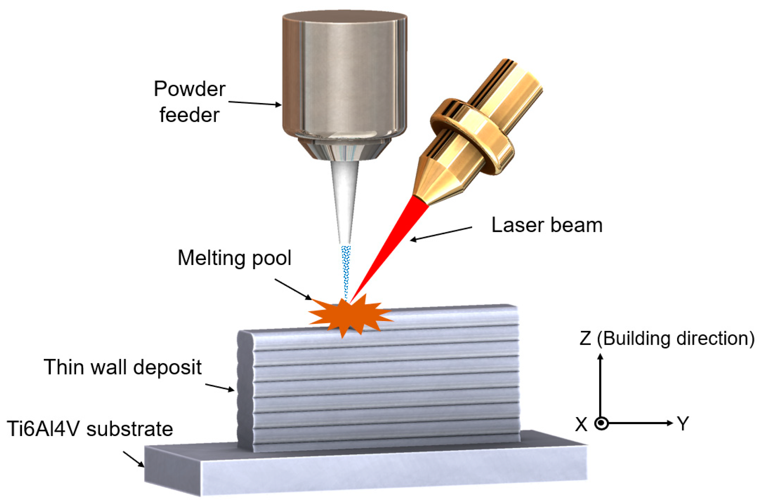
AlCoCrFeNiTi0.5 HEA samples with the nominal composition (as shown in Table 1) were prepared by LMD. Spherical gas-atomized elemental powder blends were used. The powders of Al, Co, Cr, Fe, Ni, and Ti were supplied by Micron Metals (Ramapo, NJ, USA) with 99.9% purity and 44–145 µm particle size distribution. The powder mixture (total: 276.5 g) was prepared by carefully weighing the powders using a weighing balance with an accuracy of ±0.1 mg. The mixed powders were homogenized in a Turbula mixer (Glen Mills Inc., Clifton, NJ, USA) for 1 h. The experimental setup consisted of an IPG 1 kW continuous wave YAG fiber laser (IPG Photonics, Oxford, MA, USA), a numerical control working table, and a vibration powder feeder (Powder Motion Labs, Rolla, MO, USA), as shown in Figure 1. The Grade 5 Ti6Al4V bar stock was used as the substrates (dimensions 75 mm × 12 mm × 6 mm) and cleaned with acetone to remove the dirt and oil before the experiment. The deposition process was performed in a sealed, controlled environment purged with a continuous flow of argon gas. A pre-heating was undertaken to minimize the thermal stress between the deposit and the Ti6Al4V substrate. The powders were delivered to the laser beam by an argon jet with a flow rate of 3 g/min. The deposits with a thin-wall structure were fabricated at the transverse laser speed of 200 mm/s, 2 mm laser beam size, 0.5 mm layer thickness, and the powers of 700 W for the first two layers, 600 W for the next two layers and 500 W for further layers.
2.2. Characterization
After the deposition, the specimens were sectioned by electrical discharge machining (EDM) (Hansvedt Industries Inc., Rantoul, IL, USA) and prepared by standard metallographic procedures. They were polished with 320–1200 grit SiC grinding paper, followed by 9 µm, 3 µm, 1 µm diamond solutions with a final step of 0.05 µm colloidal silica suspension. The HEA sample was etched with aqua regia (30 mL HCl and 10 mL HNO3) (Thermal Fisher Scientific, Waltham, WA, USA), and Ti6Al4V was etched with Kroll’s reagent (2 mL HF, 8 mL HNO3 and 90 mL H2O) (Thermal Fisher Scientific, Waltham, WA, USA).
The microstructure was characterized by a Helios Nanolab 600 (Thermal Fisher Scientific, Waltham, WA, USA) scanning electron microscope (SEM). The energy dispersive spectroscopy (EDS) data were collected and analyzed in the factory standardization manner (Oxford AZtec version 4.2). The electron backscatter diffraction (EBSD) scan was acquired using an Oxford HKL system with a step size of 2 µm, and data analysis was performed on HKL Channel 5 software (Oxford Instruments, Abingdon, UK). The grain was determined by a misorientation angle of 10°, and grain size was measured using the line intercept method. X-ray diffraction (XRD) profiling was performed to determine the phase constituents in the samples. The phases were identified by Phillips X’Pert diffractometer (Amsterdam, The Netherlands) using Cu-Kα radiation at 45 kV/40 mA with a scanning step of 0.05° and a scanning range from 20° to 90°. The Vickers hardness was measured using Struers Duramin hardness equipment (Struers Inc, Cleveland, OH, USA) at a 9.8 N load and a duration of 10 s. The reported hardness results were the average of ten indentations.
2.3. Oxidation Tests
The HEA and Ti6Al4V specimens for oxidation tests with dimensions of 10 mm (length) × 10 mm (width) × 2 mm (height) were prepared using EDM. Sample surfaces were subsequently polished using 320–1200 grit SiC grinding paper and cleaned with acetone. Oxidation tests were carried out in an electric furnace (DT-29-RSA, Deltech, Denver, CO, USA) under atmospheric pressure at 700 °C and 800 °C for 45 h. The samples were heated from room temperature to the target temperatures at a heating rate of 10 °C/min. The weight gain was measured before and after at specified intervals using an analytic balance (AG204, Mettler Toledo, Columbus, OH, USA) with an accuracy of 0.1 mg. The oxidized samples were characterized by XRD and SEM, as described above.
3. Results and Discussion
3.1. Microstructures of the As-Deposited HEA
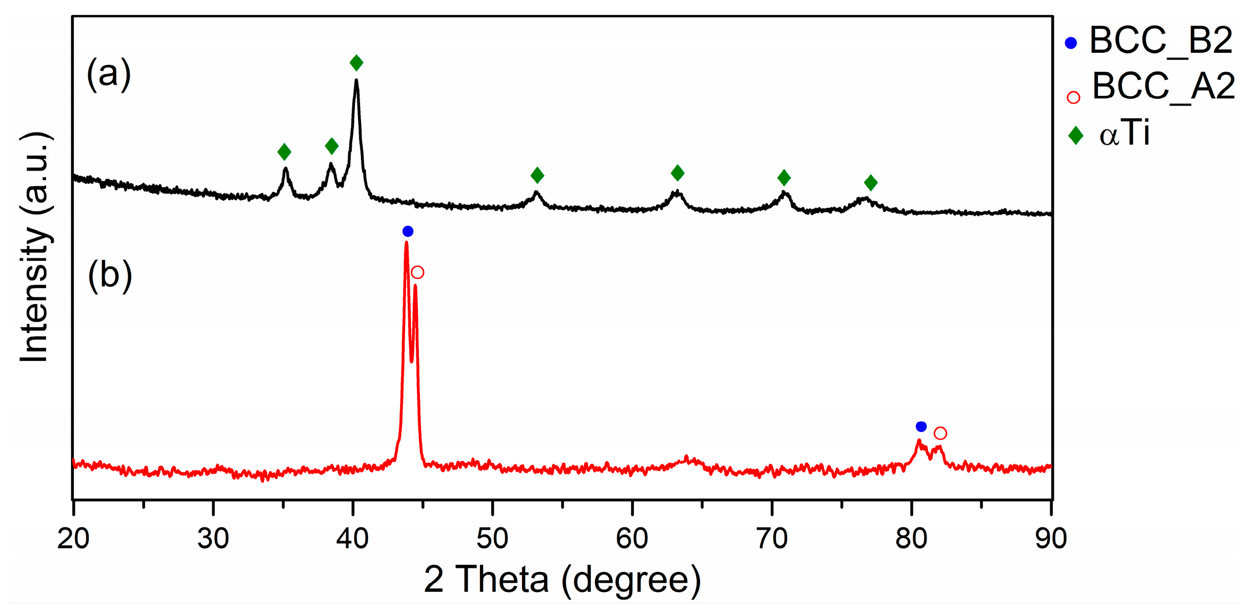
Figure 2 illustrates the XRD patterns of as-deposited AlCoCrFeNiTi0.5 HEA and the Ti6Al4V substrate. The α-Ti phase was detected in the Ti6Al4V (Figure 2a). Two BCC phases were observed in the HEA (Figure 2b), and they are ordered a BCC structure (B2) phase and a disordered BCC structure (A2) phase. Through careful analysis of the standard PDF database, the two BCC phases were identified as Al-Ni and Fe-Cr phases, which is in accordance with the similar alloys synthesized using arc-melting [23,30] and casting [33].
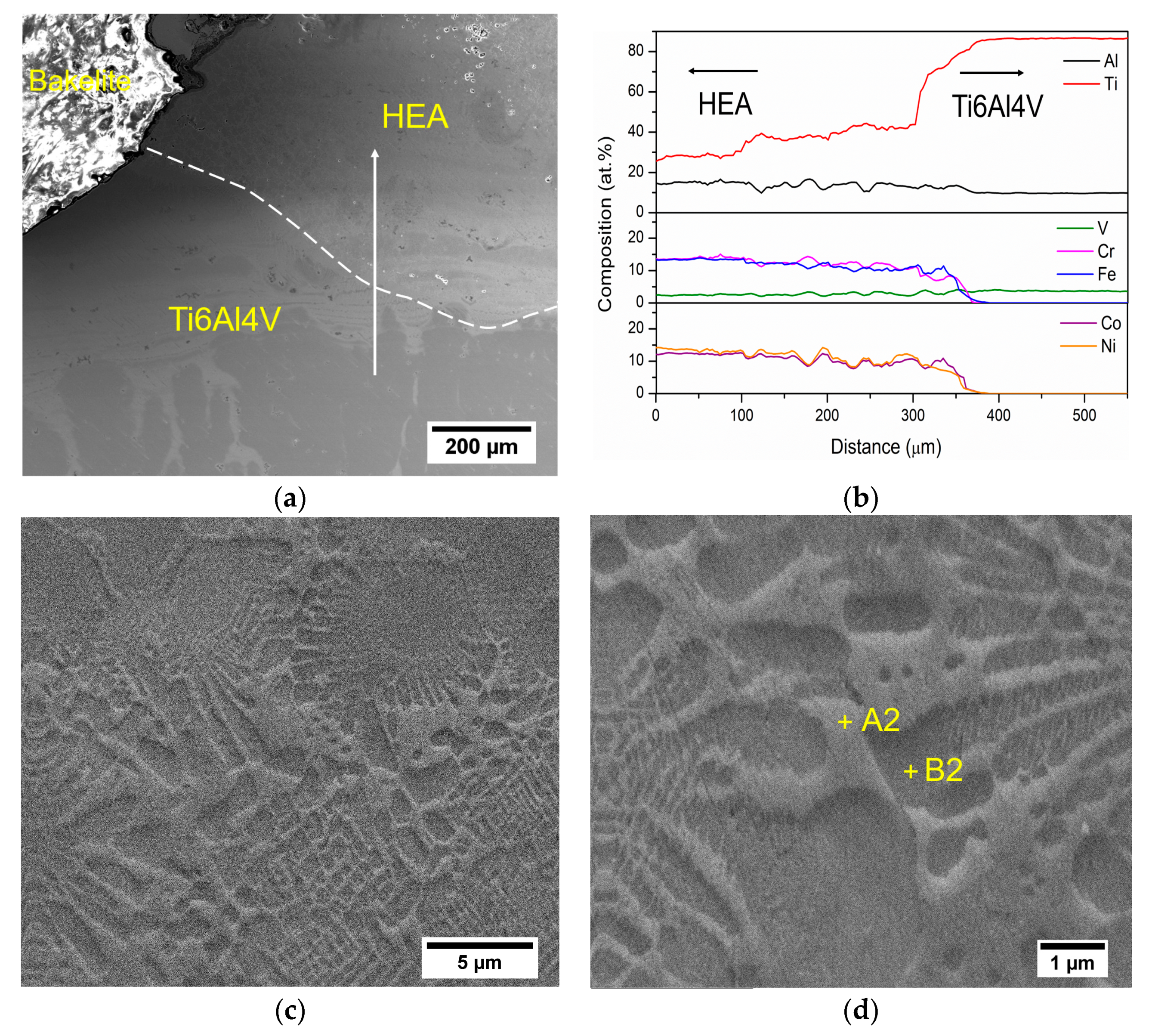
Figure 3a presents the interface between the HEA coating and the Ti6Al4V substrate, which can be seen as a good metallurgical bond without crack. The EDS line scan was used to characterize the elemental evolution from the Ti6Al4V substrate to the HEA, and the quantitative results are shown in Figure 3b. The EDS measured compositions of the Ti6Al4V substrate (Ti: ~84–86 atom%, Al: ~10–11 atom%, V: ~3–4 atom%) did not deviate from the nominal compositions of Grade 5 Ti6Al4V. Since the Ti6Al4V was mixed with the HEA layer, the elements of Al (~12–14 atom %), Co (~10–12 atom%), Cr (~11–13 atom%), Fe (~9–11 atom%), Ni (~11–14 atom%) and Ti (~36–39 atom%) were detected. A small amount of V (~1–3 atom%) was detected in the HEA layer, due to the dilution. According to the equilibrium Fe-V, Fe-Ti phase diagrams, the Fe-V or Fe-Ti intermetallic phases might be formed when the content of V was in a range of 30–65 atom% or the content of Fe was above 50 atom% [34,35,36]. From the elemental analysis above, the contents of V and Fe were low (~10 atom% or below), thus the HEA layer had a low risk of forming those intermetallic phases. Moreover, the XRD patterns obtained did not show Fe-V or Fe-Ti intermetallic phases.
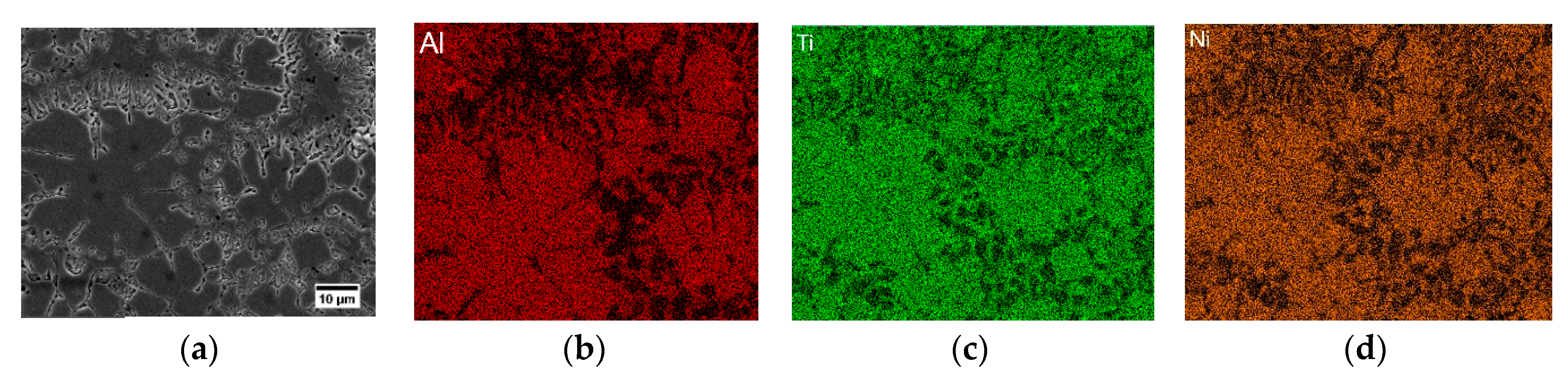
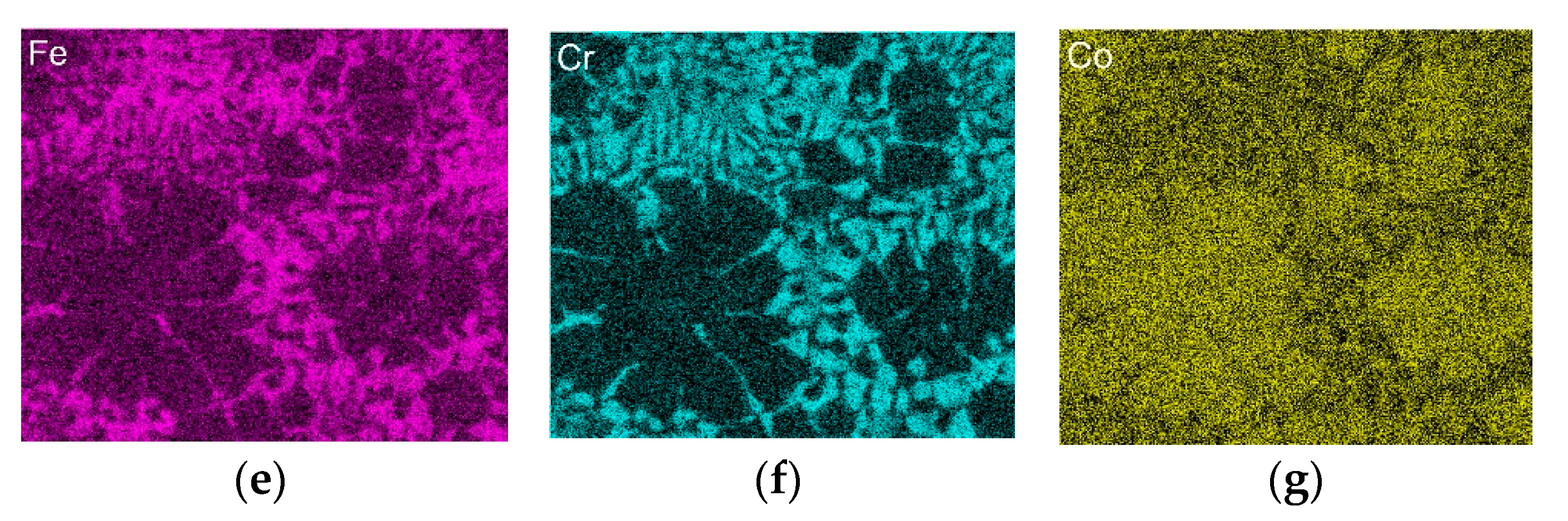
The microstructural details of the laser deposited HEA at different magnifications are shown in Figure 3c,d. The equiaxed grains were delineated by intergranular phases (Figure 3c). The dendritic structure can be observed within the equiaxed grains. The EDS was used to analyze the element distribution, and the results are listed in Table 2 and Figure 4a–g. The dark contrast phase was enriched in Al, Ni, Co, and Ti, and the high level of Fe and Cr concentration was detected in the bright contrast phase. As learned from Table 2, the chemical compositions of Fe and Cr were ~45 atom% in the bright contrast phase while were ~16 atom% in the dark contrast phase. In combination with the phase identification, the dark contrasted phases rich in Al, Ni, and Ti are B2 phase while the bright contrast phases are Fe, Cr enriched A2 phase. A similar microstructure has been observed, and it was attributed to the spinodal decomposition of B2 dendrites into B2 and A2 coexisting phases [20,23,37].
The chemical mixing enthalpies of element pairs in AlCoCrFeNiTi0.5 alloy are tabulated in Table 3. The phase formation and element segregation are determined by the mixing enthalpy among the constituent metallic elements. It is shown that Al, Ni, and Co has high negative mixing enthalpy with Ti, and they are liable to generate the B2 phase. For example, the mixing enthalpy between Al-Ti, Al-Ni, and Al-Co are −30 kJ/mol, −22 kJ/mol, and −19 kJ/mol, respectively. Furthermore, Cr and Fe tend to form the A2 phase as they exhibit low mixing enthalpy close to zero.
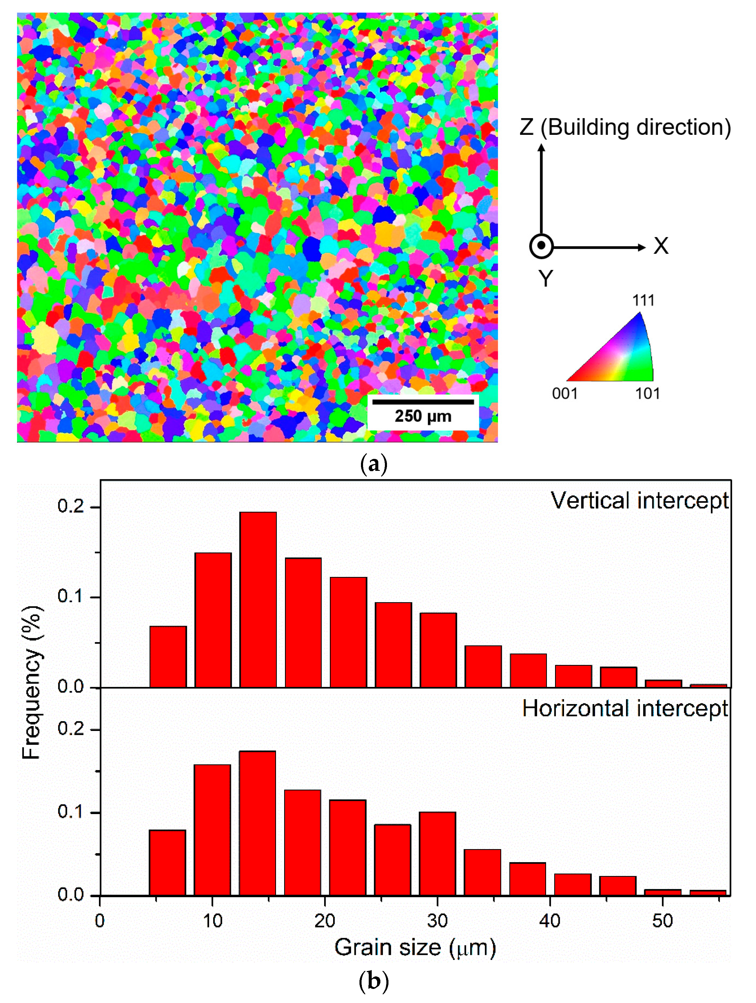
The EBSD inverse pole figure (IPF) image of a region of 1180 µm by 1056 µm taken in the XZ-plane of the as-deposited AlCoCrFeNiTi0.5 alloy is given in Figure 5a. Each individual grain in the IPF image was color-coded based on the relationship between its crystallographic orientation and the building direction, which was vertically upwards (Z direction indicated in Figure 5a). There was no obvious preferred crystallographic texture developed in the alloy because the grains were randomly color-coded. It revealed the equiaxed grains from the IPF image. Moreover, the histogram of the grain size measurement is illustrated in Figure 5b. The grain size measured by the vertical intercept was approximately 20.3 µm and was 21.1 µm along with the horizontal intercept. It has been acknowledged that, for a specific alloy, the temperature gradient G and the solidification rate R determine the solidification microstructure during the laser process. As the advancing laser moved away from the substrate, the melt pool retreated, and the solidification from moved upward, which led to the temperature field to low G and high R and the formation of the equiaxed grains. A recent study demonstrated that B2-structured dendrites were frequently fragmented, providing profuse effective nucleation sites, and therefore, promoted equiaxed grain formation in the AlCoCrFeNiTi0.5 HEA [37].
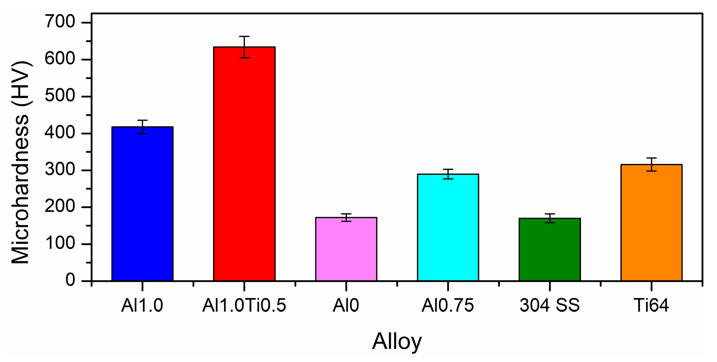
Figure 6 presents the microhardness of AlCoCrFeNiTi0.5 (Al1.0Ti0.5) HEA and Ti6Al4V (Ti64) substrate. Those of AlCoCrFeNi (Al1.0), CrCuFeNi2 (Al0), Al0.75CrCuFeNi2 (Al0.75), and AISI 304 stainless steel substrate (304 SS) alloys reported in our previous work are shown for comparison [17,18]. The addition of Ti into the AlCoCrFeNi system enhanced the microhardness from 418 HV (Al1.0) to 634 HV (Al1.0Ti0.5), which was about 2.1 times that of the Ti6Al4V substrate. Since Ti has a larger atomic radius than Al (as in Table 3), it would increase lattice distortion and improve the effect of solid solution strengthening. Our previous study reported that Al0 and Al0.75 possessed FCC phase structures, making them less resistant towards localized plastic deformation, thereby exhibiting low hardness (170 HV and 290 HV, respectively). The BCC phase consisted of a decreased number of dislocation slip systems compared to the FCC phase, which could explain the high hardness of AlCoCrFeNiTi0.5 HEA in this work.
3.2. Oxidation Behavior
3.2.1. Oxidation Kinetics
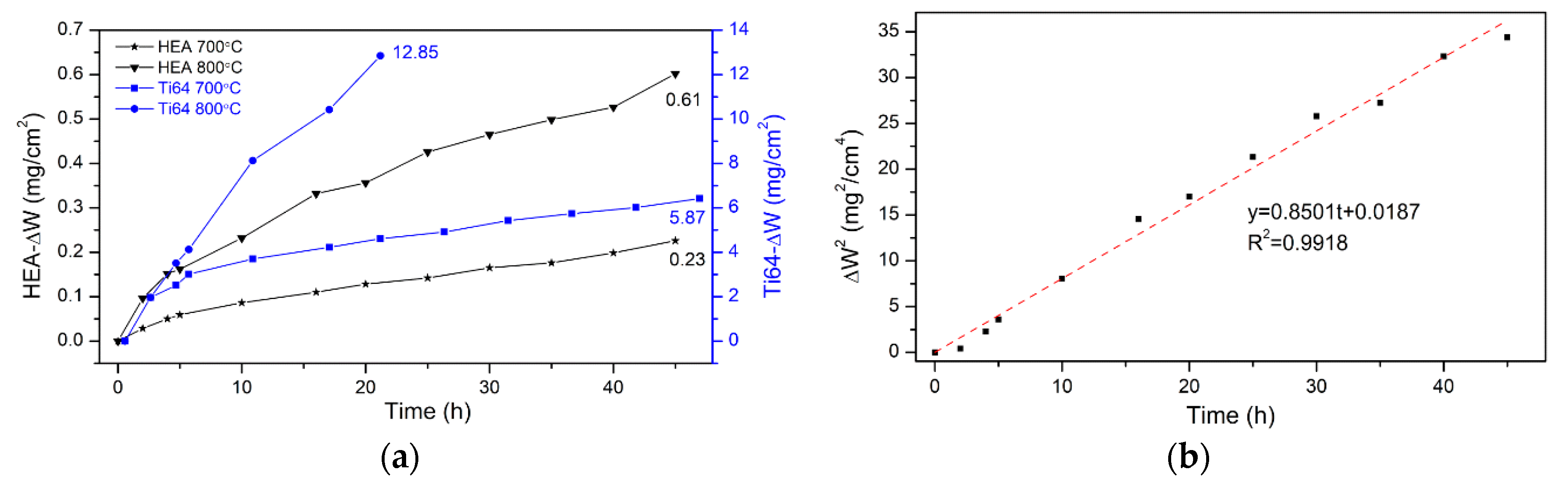
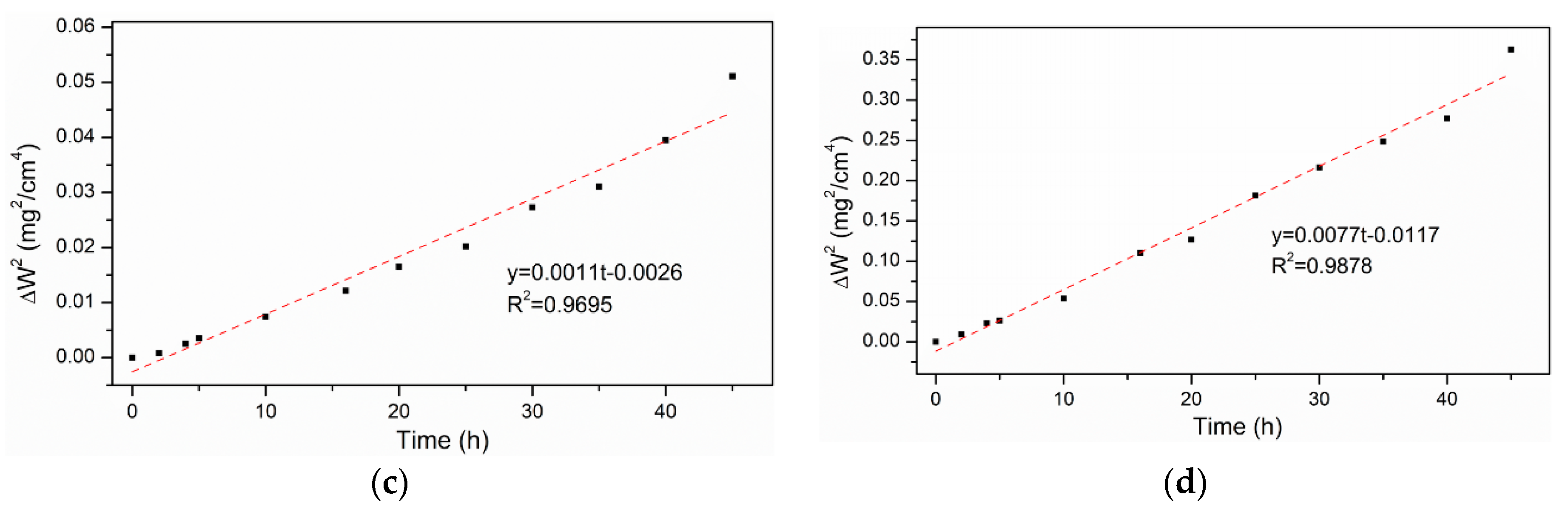
Figure 7 displays the isothermal oxidation results of the AlCoCrFeNiTi0.5 HEA and Ti6Al4V at different temperatures (700 °C and 800 °C), over a period of 45 h in the air atmosphere. As illustrated in Figure 7a, the weight gains () of the HEA were found to be 0.23 mg/cm2 and 0.61 mg/cm2 at 700 °C and 800 °C, respectively. For the Ti6Al4V alloy, its mass gain was measured at 5.87 mg/cm2 at 700 °C, and its curve was recorded only within 20 h due to the scale spalling at 800 °C. The oxidation curves were observed to follow the parabolic form. The results of the parabolic rate law plot are shown in Figure 7b–d. Here, the parabolic rate constant, can be considered as a measure of the oxidation resistance, and it was calculated using the Equation (1).
where is the mass gain (mg/cm2), A represents the unit area, is the parabolic rate constant in mg2cm−4h−1, t is the oxidation time (h), and C is a constant value. In addition, the coefficient determination R2 values (>0.95) indicate that the parabolic model fits well with the observations in Figure 7b–d. The values were determined as 0.8501 (Ti6Al4V at 700 °C), 0.0011 (HEA at 700 °C) and 0.0077 mg2cm−4h−1 (HEA at 800 °C). For discussion in Section 3.3, the values were converted to the unit of g2cm−4s−1, i.e., 2.36 × 10⁻¹⁰ (Ti6Al4V at 700 °C), 3.06 × 10⁻¹³ (HEA at 700 °C), and 2.14 × 10⁻¹² (HEA at 800 °C). Hence, better oxidation resistance was observed with the HEA as its low weight gain and parabolic rate constant.
3.2.2. Phase Analysis
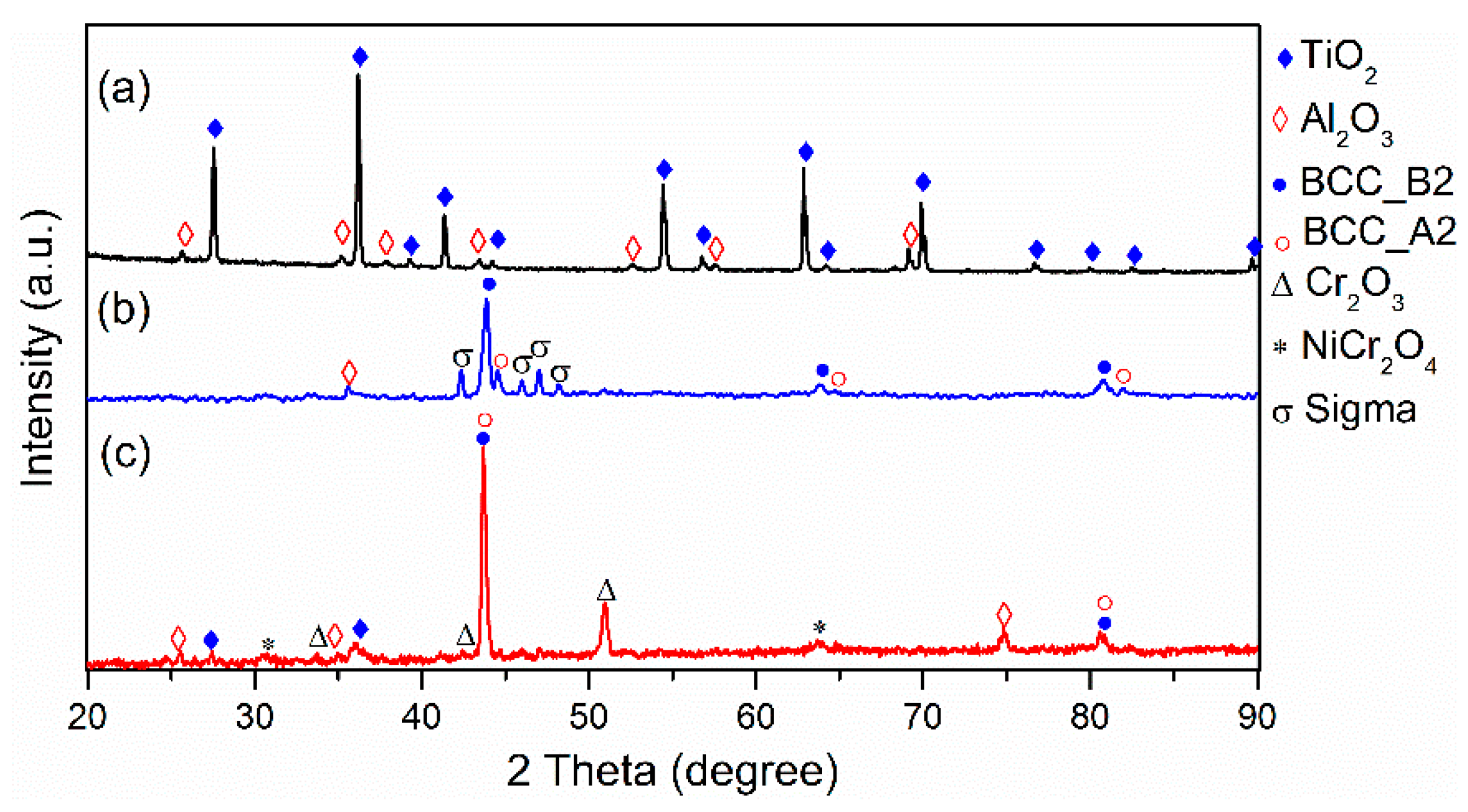
XRD analyses were performed following oxidation tests, and the results are indicated in Figure 8. The strong diffraction peaks of TiO2 and weak diffraction peaks of Al2O3 were seen from the Ti6Al4V substrate, as in Figure 8a. This illustrated that the scale formed on the Ti6Al4V substrate was mostly composed of TiO2 and a small amount of Al2O3. The TiO2 was a poorly adherent and brittle scale, and Ti and O ions could diffuse through the porous oxides, which resulted in the fast oxidation kinetics. A thick oxide scale was formed and cracked due to the thermal stress at the elevated temperature [2].
For the AlCoCrFeNiTi0.5 alloy oxidized at 700 °C, Al2O3, together with B2 and A2 phases were detected, as shown in Figure 8b. When oxidized at 800 °C, the oxides were Cr2O3, TiO2, Al2O3, and spinel (mainly composed of NiCr2O4), as in Figure 8c. Besides, a Fe-Cr sigma phase with a tetragonal structure (P42/mmm, 136) was detected in AlCoCrFeNiTi0.5 alloy oxidized shown in Figure 8b. A similar phenomenon was described by Wang et al., in which the transformation occurred from BCC to sigma phase at 650 °C [38,39].
3.2.3. Cross-Sectional Morphology of Oxide Scales
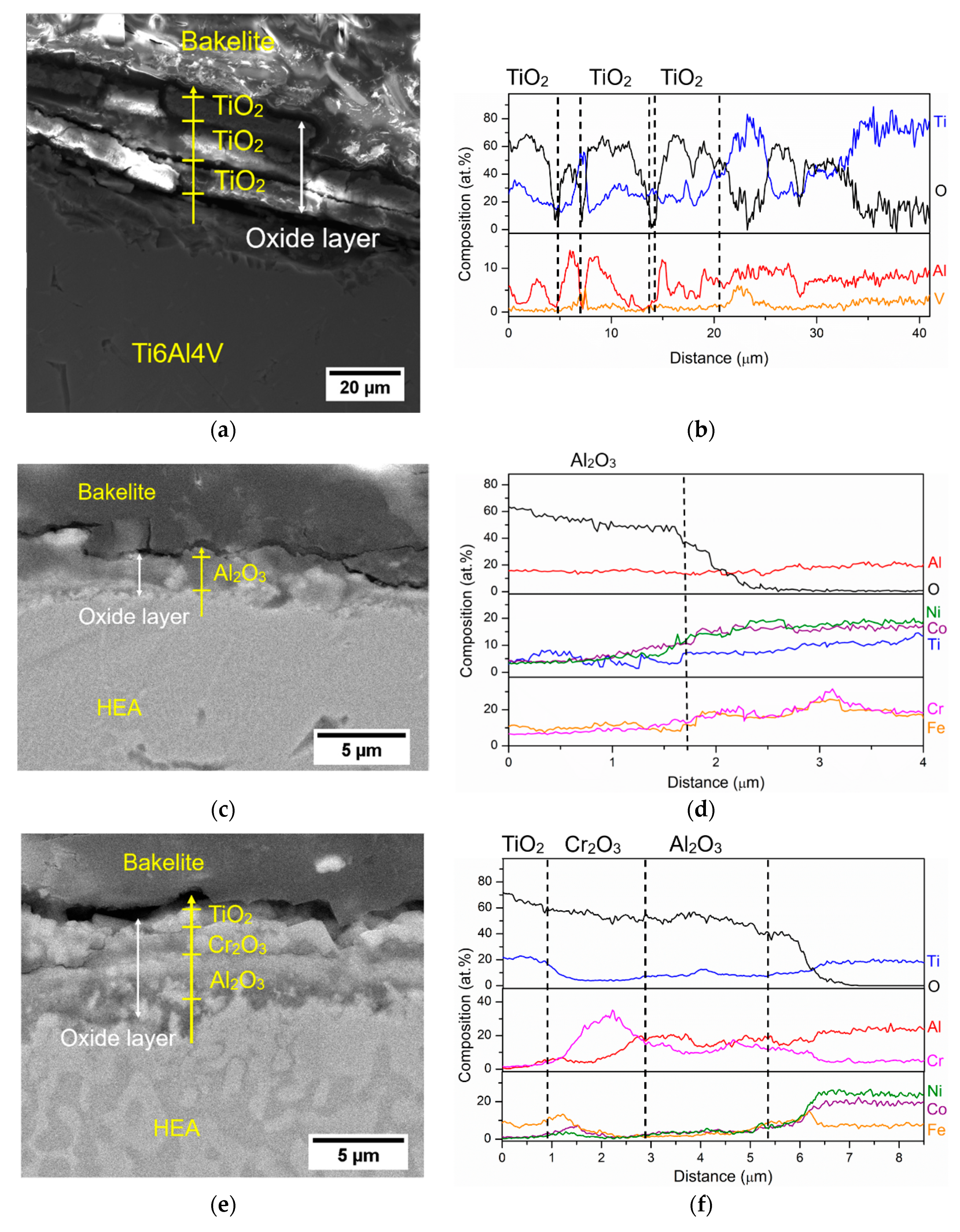
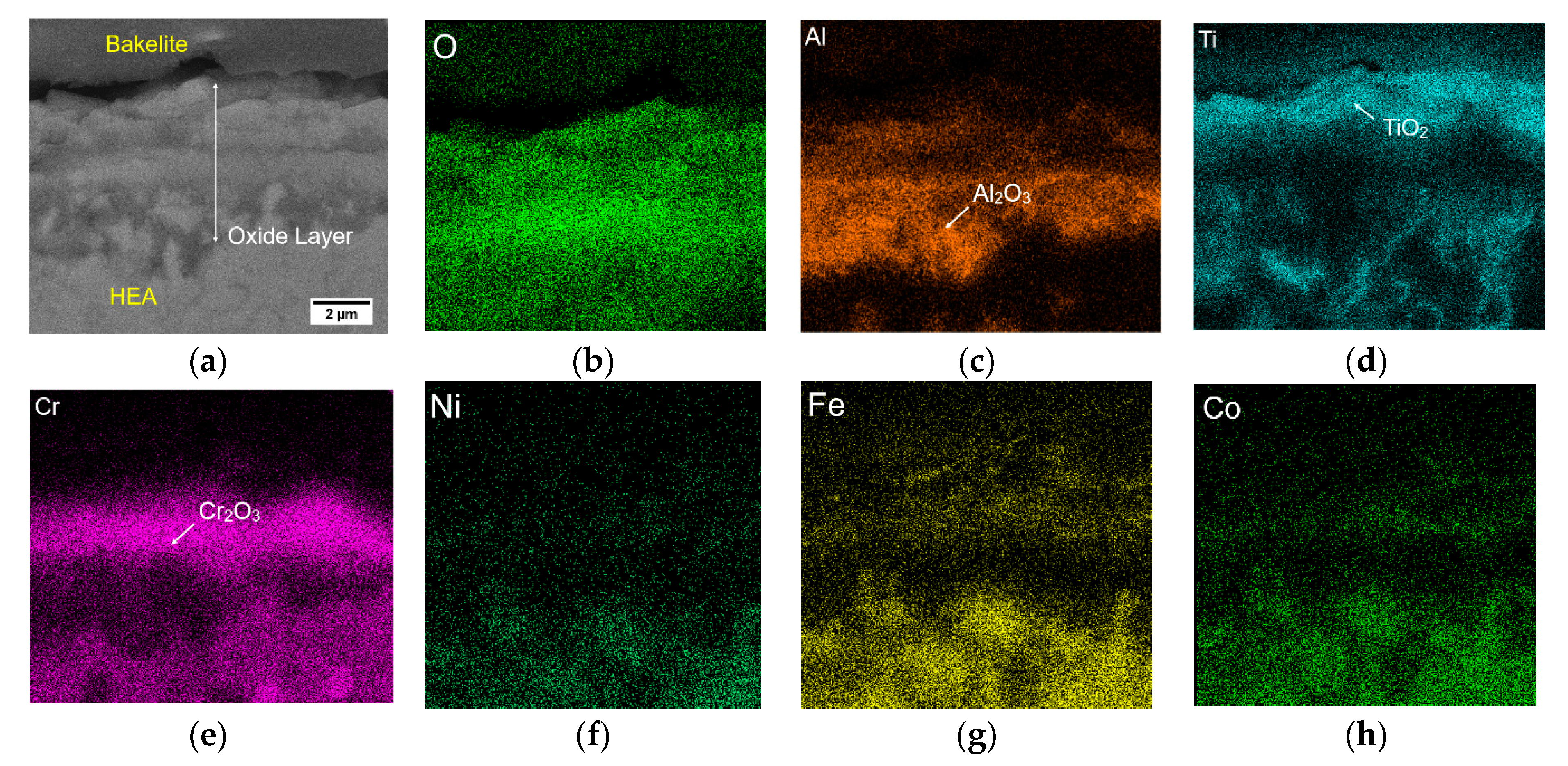
The cross-sectional backscattered electron images and the elemental composition distribution of the Ti6Al4V and AlCoCrFeNiTi0.5 HEA oxidized at 700 °C and 800 °C are present in Figure 9. The oxide scales of the Ti6Al4V had a thickness of 25.54 ± 1.85 µm and they were loose, porous, and some cracks can be observed in Figure 9a. Its main composition was TiO2, as the content of Ti was ~25–28 atom% and ~47–60 atom% of O (as in Figure 9b). EDS mapping analysis of the cross-sectional HEA oxidized at 700 °C and 800 °C was performed to reveal the oxide scales better, and the results are shown in Figure 10a–h and Figure 11a–h. The thickness of the scale on the HEA oxidized at 700 °C was about 1.73 ± 0.14 µm, of which it mainly contained Al2O3 (Al: ~15–17 atom%, O: 50–55 atom%, Ni, Cr, Co, Ti: below 10 atom% as in Figure 9c,d and this was consistent with the observation in Figure 10. The thickness of the scale on the HEA reached to 5.12 ± 0.37 µm at 800 °C in Figure 9e, corresponding to that the scale thickness increased with the oxidation temperature. The scale structure mainly comprised of TiO2 (Ti: ~20–22 atom%, O: ~63–66 atom%), Cr2O3 (Cr: ~18–21 atom%, O: ~53–56 atom%) and Al2O3 (Al: ~17–19 atom%, O: ~48–50 atom%) for the oxidized HEA at 800 °C (Figure 9f). The thickness of each layer was measured at 0.96 µm for the TiO2, 1.69 µm for the Cr2O3, and 2.51 µm for the Al2O3. This HEA mainly formed an outermost TiO2 scale, an innermost continuous Al2O3 layer, and a Cr2O3 layer in-between, as illustrated in Figure 11a–e. The formation of the continuous Cr2O3 and Al2O3 layers can actually limit the diffusion of oxygen [40], providing excellent oxidation resistance at high temperatures.
3.3. Discussion on the Oxidation Behavior
The oxidation mechanism of Ti6Al4V and AlCoCrFeNiTi0.5 HEA can be obtained from the above analysis. The predominant oxide in Ti6Al4V is TiO2, with a small amount of Al2O3 at 700 °C. Since TiO2 is brittle and loose in the oxide film, it is vulnerable to detach from the substrate when it comes to high-temperature oxidation. For the AlCoCrFeNiTi0.5 HEA, it is slightly oxidized at 700 °C, as a thin Al2O3 oxide layer is observed, and the Fe-Cr sigma phase occurs due to the phase transformation. The Al, Cr, and Ti are selectively oxidized and diffuses and enriches into the oxide layer at 800 °C. The TiO2 is distributed in the outermost oxide layer, and continuous protective Cr2O3 and Al2O3 scales are located beneath the TiO2 layer. The behavior of the AlCoCrFeNiTi0.5 HEA is similar to Group II in Ni-Cr-Al alloy systems [25,41]. The oxide map can be explained that the concentrations of Al and Cr facilitate the external Cr2O3 with an internal subscale Al2O3 scale. In a review of thermodynamic data, the standard Gibbs free energy of Al2O3 (−891 KJ/mol at 800 °C) formation is more negative than other possible oxides (i.e., Cr2O3: −569 KJ/mol) in the HEA [42], the growth of Al2O3 should be favorable during the initial stage of oxidation.
It is important and interesting to compare the oxidation rates from our work with other HEAs and conventional alloys. Table 4 collects the parabolic constants measured for different HEAs (CrMnFeCoNi, FeCoNiCrAl and Al0.5CoCrFeNiTi0.5) and alumina-forming austenitic (AFA) stainless steel. It is worth noting that the examined HEAs are comparable to those similar types of HEAs. The AlCoCrFeNiTi0.5 HEA is believed to own good oxidation properties due to the sluggish diffusion effect and formation of Al2O3 and Cr2O3 oxides. However, its oxidation resistance is shown to fall short of FeCoNiCrAl, Al1.5CoCrFeNiTi0.5 and AFA steel, i.e., 2–3 order of differences in values. According to Butler et al. [24,25], increased Al content enhanced the continuity of the Al2O3 scale, leading to improved oxidation resistance. The formed alumina could exhibit a protective effect at low Ti content. With the addition of Ti, it negatively affected the oxidation behavior of the aluminum-containing HEAs. As described in Erdogan’s work [43], a good barrier against oxidation did not form in the Ti-rich CoCrFeNiAl0.5Ti due to the fast-growing oxides.
Based on these facts, the laser processed AlCoCrFeNiTi0.5 HEA has great potential under the high-temperature application. A great effort should be put on (1) the investigation of the sequence of oxide formation at the early stage, and (2) the improvement of the oxidation resistance by alloying addition, e.g., Al, Si.
4. Conclusions
The AlCoCrFeNiTi0.5 high-entropy alloy (HEA) coating was fabricated by laser metal deposition (LMD) on a Ti6Al4V substrate. The microstructure and isothermal oxidation behavior at 700 °C and 800 °C in air atmosphere were investigated, and the underlying mechanisms were discussed. The main phase constitutions in as-deposited HEA were the Fe, Cr-rich A2 and Al, Ni, and Ti-enriched B2 phases. The isothermal oxidation testing demonstrated that the HEA coatings could effectively improve the oxidation resistance of the Ti6Al4V substrate. The oxidation kinetics of the HEA and Ti6Al4V met the parabolic rate law, while the weight gain and parabolic rate constant of the HEA were lower than Ti6Al4V, implying a better oxidation resistance. The scales of the Ti6Al4V were mainly composed of TiO2 at 700 °C, and it suffered from spalling at 800 °C. The AlCoCrFeNiTi0.5 HEA was slightly oxidized at 700 °C as a few oxides were formed. At 800 °C, the formation of continuous Al2O3, Cr2O3 scales could be ascribed to their good oxidation resistance of the HEA. This work provides an approach to enhance the oxidation resistance of Ti6Al4V alloy and accelerate the broad adoption of HEAs in high-temperature applications.
Author Contributions
W.C. designed, conducted the experiment, and wrote the manuscript; W.-T.C. and W.L. assisted in results analysis; W.-T.C. assisted in SEM imaging; F.L. supervised the research project. The authors reviewed the manuscript. All authors have read and agreed to the published version of the manuscript.
Funding
Wenyuan Cui and Frank Liou are grateful for the financial support from NSF (National Science Foundation) grants CMMI-1625736 and EEC-1937128, and Intelligent System Center (ISC) at Missouri University of Science and Technology (Missouri S&T).
Acknowledgments
The materials preparation and characterization were supported by the Materials Research Center (MRC) at Missouri S&T. Wenyuan Cui would like to thank Jiaqi Duan, Austin J. Martin, and Eric Bohannan from Missouri S&T for their support and discussions.
Conflicts of Interest
The authors declare no conflict of interest.
References
- Guleryuz, H.; Cimenoglu, H. Oxidation of Ti-6Al-4V alloy. J. Alloy. Compd. 2009, 472, 241–246. [Google Scholar] [CrossRef]
- Huang, C.; Zhang, Y.; Shen, J.; Vilar, R. Thermal stability and oxidation resistance of laser clad TiVCrAlSi high entropy alloy coatings on Ti-6Al-4V alloy. Surf. Coat. Technol. 2011, 206, 1389–1395. [Google Scholar] [CrossRef]
- Weng, F.; Chen, C.; Yu, H. Research status of laser cladding on titanium and its alloys: A review. Mater. Des. 2014, 58, 412–425. [Google Scholar] [CrossRef]
- Lv, Y.H.; Li, J.; Tao, Y.F.; Hu, L.F. High-temperature wear and oxidation behaviors of TiNi/Ti 2 Ni matrix composite coatings with TaC addition prepared on Ti6Al4V by laser cladding. Appl. Surf. Sci. 2017, 402, 478–494. [Google Scholar] [CrossRef]
- Kumar, S.; Sankara Narayanan, T.S.N.; Ganesh Sundara Raman, S.; Seshadri, S.K. Thermal oxidation of Ti6Al4V alloy: Microstructural and electrochemical characterization. Mater. Chem. Phys. 2010, 119, 337–346. [Google Scholar] [CrossRef]
- Zhou, Z.Y.; Liu, X.B.; Zhuang, S.G.; Wang, M.; Luo, Y.S.; Tu, R.; Zhou, S.F. Laser in-situ synthesizing Ti5Si3/Al3Ni2 reinforced Al3Ti/NiTi composite coatings: Microstructure, mechanical characteristics and oxidation behavior. Opt. Laser Technol. 2019, 109, 99–109. [Google Scholar] [CrossRef]
- Bobbio, L.D.; Otis, R.A.; Borgonia, J.P.; Dillon, R.P.; Shapiro, A.A.; Liu, Z.K.; Beese, A.M. Additive manufacturing of a functionally graded material from Ti-6Al-4V to Invar: Experimental characterization and thermodynamic calculations. Acta Mater. 2017, 127, 133–142. [Google Scholar] [CrossRef]
- Reichardt, A.; Dillon, R.P.; Borgonia, J.P.; Shapiro, A.A.; McEnerney, B.W.; Momose, T.; Hosemann, P. Development and characterization of Ti-6Al-4V to 304L stainless steel gradient components fabricated with laser deposition additive manufacturing. Mater. Des. 2016, 104, 404–413. [Google Scholar] [CrossRef]
- Li, W.; Ghazanfari, A.; McMillen, D.; Leu, M.C.; Hilmas, G.E.; Watts, J. Characterization of zirconia specimens fabricated by ceramic on-demand extrusion. Ceram. Int. 2018, 44, 12245–12252. [Google Scholar] [CrossRef]
- Li, W.; Ghazanfari, A.; McMillen, D.; Leu, M.C.; Hilmas, G.E.; Watts, J. Fabricating ceramic components with water dissolvable support structures by the Ceramic On-Demand Extrusion process. CIRP Ann. Manuf. Technol. 2017, 66, 225–228. [Google Scholar] [CrossRef]
- Cui, W.; Zhang, Y.; Zhang, X.; Li, L.; Liou, F. Metal Additive Manufacturing Parts Inspection Using Convolutional Neural Network. Appl. Sci. 2020, 10, 545. [Google Scholar] [CrossRef] [Green Version]
- Liu, H.; Zhang, X.; Jiang, Y.; Zhou, R. Microstructure and high temperature oxidation resistance of in-situ synthesized TiN/Ti3Al intermetallic composite coatings on Ti6Al4V alloy by laser cladding process. J. Alloy. Compd. 2016, 670, 268–274. [Google Scholar] [CrossRef]
- Zambrano Carrullo, J.C.; Pereira Falcón, J.C.; Amigó Borrás, V. Influence of process parameters and initial microstructure on the oxidation resistance of Ti48Al2Cr2Nb coating obtained by laser metal deposition. Surf. Coat. Technol. 2019, 358, 114–124. [Google Scholar] [CrossRef]
- Liu, F.; Mao, Y.; Lin, X.; Zhou, B.; Qian, T. Microstructure and high temperature oxidation resistance of Ti-Ni gradient coating on TA2 titanium alloy fabricated by laser cladding. Opt. Laser Technol. 2016, 83, 140–147. [Google Scholar] [CrossRef]
- Liu, X.B.; Wang, H.M. Microstructure, wear and high-temperature oxidation resistance of laser clad Ti5Si3/γ/TiSi composite coatings on γ-TiAl intermetallic alloy. Surf. Coat. Technol. 2006, 200, 4462–4470. [Google Scholar] [CrossRef]
- Yeh, J.-W.; Chen, S.-K.; Lin, S.-J.; Gan, J.-Y.; Chin, T.-S.; Shun, T.-T.; Tsau, C.-H.; Chang, S.-Y. Nanostructured High-Entropy Alloys with Multiple Principal Elements: Novel Alloy Design Concepts and Outcomes. Adv. Eng. Mater. 2004, 6, 299–303. [Google Scholar] [CrossRef]
- Cui, W.; Karnati, S.; Zhang, X.; Burns, E.; Liou, F. Fabrication of AlCoCrFeNi High-Entropy Alloy Coating on an AISI 304 Substrate via a CoFe2Ni Intermediate Layer. Entropy 2019, 21, 2. [Google Scholar] [CrossRef] [Green Version]
- Cui, W.; Zhang, X.; Li, L.; Chen, Y.; Pan, T.; Liou, F. Fabrication and Characterization of AlxCrCuFeNi2 High-Entropy Alloys Coatings by Laser Metal Deposition. Procedia Manuf. 2019, 39, 509–518. [Google Scholar] [CrossRef]
- Wang, Y.P.; Li, B.S.; Ren, M.X.; Yang, C.; Fu, H.Z. Microstructure and compressive properties of AlCrFeCoNi high entropy alloy. Mater. Sci. Eng. A 2008, 491, 154–158. [Google Scholar] [CrossRef]
- Tang, Z.; Senkov, O.N.; Parish, C.M.; Zhang, C.; Zhang, F.; Santodonato, L.J.; Wang, G.; Zhao, G.; Yang, F.; Liaw, P.K. Tensile ductility of an AlCoCrFeNi multi-phase high-entropy alloy through hot isostatic pressing (HIP) and homogenization. Mater. Sci. Eng. A 2015, 647, 229–240. [Google Scholar] [CrossRef] [Green Version]
- Wang, R.; Zhang, K.; Davies, C.; Wu, X. Evolution of microstructure, mechanical and corrosion properties of AlCoCrFeNi high-entropy alloy prepared by direct laser fabrication. J. Alloy. Compd. 2017, 694, 971–981. [Google Scholar] [CrossRef]
- Tsai, K.Y.; Tsai, M.H.; Yeh, J.W. Sluggish diffusion in Co-Cr-Fe-Mn-Ni high-entropy alloys. Acta Mater. 2013, 61, 4887–4897. [Google Scholar] [CrossRef]
- Nong, Z.S.; Lei, Y.N.; Zhu, J.C. Wear and oxidation resistances of AlCrFeNiTi-based high entropy alloys. Intermetallics 2018, 101, 144–151. [Google Scholar] [CrossRef]
- Mohanty, A.; Sampreeth, J.K.; Bembalge, O.; Hascoet, J.Y.; Marya, S.; Immanuel, R.J.; Panigrahi, S.K. High temperature oxidation study of direct laser deposited AlXCoCrFeNi (X = 0.3,0.7) high entropy alloys. Surf. Coat. Technol. 2019, 380, 125028. [Google Scholar] [CrossRef]
- Butler, T.M.; Weaver, M.L. Oxidation behavior of arc melted AlCoCrFeNi multi-component high-entropy alloys. J. Alloy. Compd. 2016, 674, 229–244. [Google Scholar] [CrossRef]
- Butler, T.M.; Alfano, J.P.; Martens, R.L.; Weaver, M.L. High-Temperature Oxidation Behavior of Al-Co-Cr-Ni-(Fe or Si) Multicomponent High-Entropy Alloys. JOM 2015, 67, 246–259. [Google Scholar] [CrossRef]
- Dąbrowa, J.; Cieślak, G.; Stygar, M.; Mroczka, K.; Berent, K.; Kulik, T.; Danielewski, M. Influence of Cu content on high temperature oxidation behavior of AlCoCrCuxFeNi high entropy alloys (x = 0; 0.5; 1). Intermetallics 2017, 84, 52–61. [Google Scholar] [CrossRef]
- Feng, R.; Gao, M.C.; Zhang, C.; Guo, W.; Poplawsky, J.D.; Zhang, F.; Hawk, J.A.; Neuefeind, J.C.; Ren, Y.; Liaw, P.K. Phase stability and transformation in a light-weight high-entropy alloy. Acta Mater. 2018, 146, 280–293. [Google Scholar] [CrossRef]
- Löbel, M.; Lindner, T.; Mehner, T.; Lampke, T. Influence of Titanium on Microstructure, Phase Formation and Wear Behaviour of AlCoCrFeNiTix High-Entropy Alloy. Entropy 2018, 20, 505. [Google Scholar] [CrossRef] [Green Version]
- Jiang, S.; Lin, Z.; Xu, H.; Sun, Y. Studies on the microstructure and properties of AlxCoCrFeNiTi1-x high entropy alloys. J. Alloy. Compd. 2018, 741, 826–833. [Google Scholar] [CrossRef]
- Tian, L.H.; Xiong, W.; Liu, C.; Lu, S.; Fu, M. Microstructure and Wear Behavior of Atmospheric Plasma-Sprayed AlCoCrFeNiTi High-Entropy Alloy Coating. J. Mater. Eng. Perform. 2016, 25, 5513–5521. [Google Scholar] [CrossRef]
- Li, Q.H.; Yue, T.M.; Guo, Z.N.; Lin, X. Microstructure and corrosion properties of alcocrfeni high entropy alloy coatings deposited on AISI 1045 steel by the electrospark process. Metall. Mater. Trans. A Phys. Metall. Mater. Sci. 2013, 44, 1767–1778. [Google Scholar] [CrossRef]
- Yu, Y.; Wang, J.; Li, J.; Kou, H.; Liu, W. Characterization of BCC phases in AlCoCrFeNiTix high entropy alloys. Mater. Lett. 2015, 138, 78–80. [Google Scholar] [CrossRef]
- Bobbio, L.D.; Bocklund, B.; Otis, R.; Borgonia, J.P.; Dillon, R.P.; Shapiro, A.A.; McEnerney, B.; Liu, Z.K.; Beese, A.M. Characterization of a functionally graded material of Ti-6Al-4V to 304L stainless steel with an intermediate V section. J. Alloy. Compd. 2018, 742, 1031–1036. [Google Scholar] [CrossRef]
- Chen, S.; Zhang, M.; Huang, J.; Cui, C.; Zhang, H.; Zhao, X. Microstructures and mechanical property of laser butt welding of titanium alloy to stainless steel. Mater. Des. 2014, 53, 504–511. [Google Scholar] [CrossRef]
- von Goldbeck, O.K. IRON—Binary Phase Diagrams; Springer: Berlin/Heidelberg, Germany, 1982. [Google Scholar]
- Guan, S.; Solberg, K.; Wan, D.; Berto, F.; Welo, T.; Yue, T.M.; Chan, K.C. Formation of fully equiaxed grain microstructure in additively manufactured AlCoCrFeNiTi0.5 high entropy alloy. Mater. Des. 2019, 184, 108202. [Google Scholar] [CrossRef]
- Yu, Y.; Wang, J.; Li, J.; Yang, J.; Kou, H.; Liu, W. Tribological Behavior of AlCoCrFeNi(Ti0.5) High Entropy Alloys under Oil and MACs Lubrication. J. Mater. Sci. Technol. 2016, 32, 470–476. [Google Scholar] [CrossRef]
- Munitz, A.; Salhov, S.; Hayun, S.; Frage, N. Heat treatment impacts the micro-structure and mechanical properties of AlCoCrFeNi high entropy alloy. J. Alloy. Compd. 2016, 683, 221–230. [Google Scholar] [CrossRef]
- Chen, W.T.; Gleeson, B.; Heuer, A. Oxidation Behavior of γ′-Ni3Al-Based Ni–20Al–5Cr Alloys With and Without Reactive Elements Under Different Heating Conditions. Oxid. Met. 2019, 92, 137–150. [Google Scholar] [CrossRef]
- Giggins, C.S.; Pettit, F.S. Oxidation of Ni-Cr-Al Alloys Between 1000° and 1200 °C. J. Electrochem. Soc. 1971, 118, 1782. [Google Scholar] [CrossRef]
- Zhang, P.; Li, Y.; Chen, Z.; Zhang, J.; Shen, B. Oxidation response of a vacuum arc melted NbZrTiCrAl refractory high entropy alloy at 800–1200 °C. Vacuum 2019, 162, 20–27. [Google Scholar] [CrossRef]
- Erdogan, A.; Doleker, K.M.; Zeytin, S. Effect of Al and Ti on High-Temperature Oxidation Behavior of CoCrFeNi-Based High-Entropy Alloys. JOM 2019, 71, 3499–3510. [Google Scholar] [CrossRef]
- Laplanche, G.; Volkert, U.F.; Eggeler, G.; George, E.P. Oxidation Behavior of the CrMnFeCoNi High-Entropy Alloy. Oxid. Met. 2016, 85, 629–645. [Google Scholar] [CrossRef]
- Kai, W.; Li, C.C.; Cheng, F.P.; Chu, K.P.; Huang, R.T.; Tsay, L.W.; Kai, J.J. Air-oxidation of FeCoNiCr-based quinary high-entropy alloys at 700–900 °C. Corros. Sci. 2017, 121, 116–125. [Google Scholar] [CrossRef]
- Wang, S.; Chen, Z.; Zhang, P.; Zhang, K.; Chen, C.L.; Shen, B.L. Influence of Al content on high temperature oxidation behavior of Al x CoCrFeNiTi 0.5 high entropy alloys. Vacuum 2019, 163, 263–268. [Google Scholar] [CrossRef]
- Rashidi, S.; Choi, J.P.; Stevenson, J.W.; Pandey, A.; Gupta, R.K. Effect of Aluminizing on the High-Temperature Oxidation Behavior of an Alumina-Forming Austenitic Stainless Steel. JOM 2019, 71, 109–115. [Google Scholar] [CrossRef]
- Wang, J.; Qiao, Y.; Dong, N.; Fang, X.; Quan, X.; Cui, Y.; Han, P. The Influence of Temperature on the Oxidation Mechanism in Air of HR3C and Aluminum-Containing 22Cr–25Ni Austenitic Stainless Steels. Oxid. Met. 2018, 89, 713–730. [Google Scholar] [CrossRef]
Figure 1.
Schematic of the laser metal deposition (LMD) experiment setup.

Figure 2.
X-ray diffraction (XRD) pattern of the (a) Ti6Al4V substrate and (b) as-deposited AlCoCrFeNiTi0.5 HEA.
Figure 2.
X-ray diffraction (XRD) pattern of the (a) Ti6Al4V substrate and (b) as-deposited AlCoCrFeNiTi0.5 HEA.

Figure 3.
(a) Secondary electron images of the interface between the AlCoCrFeNiTi0.5 HEA coating and Ti6Al4V substrate, (b) energy dispersive spectroscopy (EDS) line scan along the white arrow line in (a), (c,d) backscattered electron images of the HEA microstructure at different magnifications.
Figure 3.
(a) Secondary electron images of the interface between the AlCoCrFeNiTi0.5 HEA coating and Ti6Al4V substrate, (b) energy dispersive spectroscopy (EDS) line scan along the white arrow line in (a), (c,d) backscattered electron images of the HEA microstructure at different magnifications.

Figure 4.
(a) Secondary electron image and the corresponding elemental maps of (b) Al, (c) Ti, (d) Ni, (e) Fe, (f) Cr, and (g) Co of the AlCoCrFeNiTi0.5 HEA.
Figure 4.
(a) Secondary electron image and the corresponding elemental maps of (b) Al, (c) Ti, (d) Ni, (e) Fe, (f) Cr, and (g) Co of the AlCoCrFeNiTi0.5 HEA.


Figure 5.
(a) Electron backscatter diffraction (EBSD)-inverse pole figure (IPF) map of the XZ-plane in the as-deposited HEA sample, and (b) histogram of the grain size measurement.
Figure 5.
(a) Electron backscatter diffraction (EBSD)-inverse pole figure (IPF) map of the XZ-plane in the as-deposited HEA sample, and (b) histogram of the grain size measurement.


Figure 7.
Isothermal oxidation results of AlCoCrFeNiTi0.5 HEA and Ti6Al4V at 700 °C and 800 °C for 45 h; (a) weight gain versus oxidation time curves, the parabolic plot for (b)Ti6Al4V at 700 °C, (c) HEA at 700 °C and (d) HEA at 800 °C.
Figure 7.
Isothermal oxidation results of AlCoCrFeNiTi0.5 HEA and Ti6Al4V at 700 °C and 800 °C for 45 h; (a) weight gain versus oxidation time curves, the parabolic plot for (b)Ti6Al4V at 700 °C, (c) HEA at 700 °C and (d) HEA at 800 °C.


Figure 8.
XRD patterns of the oxidized (a) Ti6Al4V at 700 °C, (b) HEA at 700 °C, and (c) HEA at 800 °C for 45 h.
Figure 8.
XRD patterns of the oxidized (a) Ti6Al4V at 700 °C, (b) HEA at 700 °C, and (c) HEA at 800 °C for 45 h.

Figure 9.
Cross-sectional backscattered electron images and the corresponding elemental composition distribution along the yellow arrow for the oxidized: (a) and (b) Ti6Al4V at 700 °C, (c) and (d) HEA at 700 °C, (e) and (f) HEA at 800 °C for 45 h.
Figure 9.
Cross-sectional backscattered electron images and the corresponding elemental composition distribution along the yellow arrow for the oxidized: (a) and (b) Ti6Al4V at 700 °C, (c) and (d) HEA at 700 °C, (e) and (f) HEA at 800 °C for 45 h.

Figure 10.
(a) Backscattered electron image and the corresponding (b) O, (c) Al, (d) Ti, (e) Cr, (f) Ni, (g) Fe and (h) Co EDS maps of the oxide scales on AlCoCrFeNiTi0.5 HEA oxidized at 700 °C for 45 h.
Figure 10.
(a) Backscattered electron image and the corresponding (b) O, (c) Al, (d) Ti, (e) Cr, (f) Ni, (g) Fe and (h) Co EDS maps of the oxide scales on AlCoCrFeNiTi0.5 HEA oxidized at 700 °C for 45 h.

Figure 11.
(a) Backscattered electron image and the corresponding (b) O, (c) Al, (d) Ti, (e) Cr, (f) Ni, (g) Fe and (h) Co EDS maps of the oxide scales on AlCoCrFeNiTi0.5 HEA oxidized at 800 °C for 45 h.
Figure 11.
(a) Backscattered electron image and the corresponding (b) O, (c) Al, (d) Ti, (e) Cr, (f) Ni, (g) Fe and (h) Co EDS maps of the oxide scales on AlCoCrFeNiTi0.5 HEA oxidized at 800 °C for 45 h.


Table 1.
Nominal composition (atom%) of an AlCoCrFeNiTi0.5 high-entropy alloy (HEA).
| Al | Co | Cr | Fe | Ni | Ti | |
|---|---|---|---|---|---|---|
| Atom% | 18.2 | 18.2 | 18.2 | 18.2 | 18.2 | 9.0 |
Table 2.
Elemental composition (atom %) of each phase in the HEA by SEM-EDS (more than 5 locations).
Table 2.
Elemental composition (atom %) of each phase in the HEA by SEM-EDS (more than 5 locations).
| Phase | Element | |||||
|---|---|---|---|---|---|---|
| Al | Co | Cr | Fe | Ni | Ti | |
| B2 | 24.8 ± 1.6 | 17 ± 1.0 | 7.2 ± 0.7 | 8.4 ± 1.1 | 21.2 ± 0.6 | 20 ± 1.7 |
| A2 | 15.5 ± 2.1 | 13.8 ± 1.4 | 19.7 ± 1.2 | 25.4 ± 1.3 | 14.3 ± 0.9 | 12.1 ± 0.5 |
| Element | Al | Co | Cr | Fe | Ni | Ti |
|---|---|---|---|---|---|---|
| (Atomic Size, nm) | (0.143) | (0.125) | (0.127) | (0.127) | (0.125) | (0.145) |
| Al | −19 | −10 | −11 | −22 | −30 | |
| Co | −4 | −1 | 0 | −28 | ||
| Cr | −1 | −7 | −7 | |||
| Fe | −2 | −17 | ||||
| Ni | −35 |
Table 4.
The values of the parabolic constants for various alloys.
| Alloy | (g2mg−4s−1) | Temperature (°C) | Reference |
|---|---|---|---|
| AlCoCrFeNiTi0.5 | 3.06 × 10⁻¹³ | 700 | This work |
| 2.14 × 10⁻¹² | 800 | ||
| CrMnFeCoNi | 5.47 × 10⁻¹² | 700 | [44] |
| 1.67 × 10⁻¹¹ | 800 | ||
| FeCoNiCrAl | 8.5 × 10⁻¹⁵ | 700 | [45] |
| 4.0 × 10⁻¹⁴ | 800 | ||
| Al1.5CoCrFeNiTi0.5 | 1.66 × 10⁻¹⁴ | 700 | [46] |
| 14Cr-25Ni-3.5Al AFA steel | 3 × 10⁻¹⁴ | 850 | [47] |
| 22Cr-25Ni-2.5Al AFA steel | 9.19 × 10⁻¹⁵ | 700 | [48] |
| 3.55 × 10⁻¹⁴ | 800 |
© 2020 by the authors. Licensee MDPI, Basel, Switzerland. This article is an open access article distributed under the terms and conditions of the Creative Commons Attribution (CC BY) license (http://creativecommons.org/licenses/by/4.0/).
Share and Cite
MDPI and ACS Style
Cui, W.; Li, W.; Chen, W.-T.; Liou, F. Laser Metal Deposition of an AlCoCrFeNiTi0.5 High-Entropy Alloy Coating on a Ti6Al4V Substrate: Microstructure and Oxidation Behavior. Crystals 2020, 10, 638. https://doi.org/10.3390/cryst10080638
AMA Style
Cui W, Li W, Chen W-T, Liou F. Laser Metal Deposition of an AlCoCrFeNiTi0.5 High-Entropy Alloy Coating on a Ti6Al4V Substrate: Microstructure and Oxidation Behavior. Crystals. 2020; 10(8):638. https://doi.org/10.3390/cryst10080638
Chicago/Turabian StyleCui, Wenyuan, Wei Li, Wei-Ting Chen, and Frank Liou. 2020. "Laser Metal Deposition of an AlCoCrFeNiTi0.5 High-Entropy Alloy Coating on a Ti6Al4V Substrate: Microstructure and Oxidation Behavior" Crystals 10, no. 8: 638. https://doi.org/10.3390/cryst10080638
Note that from the first issue of 2016, this journal uses article numbers instead of page numbers. See further details here.