CFD Simulation on Workability of a Seaweed Harvesting Boat Due to Wake-Wash


1
Department of Naval Architecture & Ocean Engineering, Pusan National University, Busan 46241, Korea
2
Future Ship Research Department, Korea Shipbuilding & Offshore Engineering Co. Ltd., Gyeonggi-do 13591, Korea
3
R&D Center, Haemin Heavy Industry Co. Ltd., Busan 46751, Korea
*
Author to whom correspondence should be addressed.
J. Mar. Sci. Eng. 2020, 8(8), 544; https://doi.org/10.3390/jmse8080544
Submission received: 21 May 2020
/
Revised: 19 July 2020
/
Accepted: 20 July 2020
/
Published: 22 July 2020
(This article belongs to the Section Coastal Engineering)
Abstract
:In the present study, a 2-ton class seaweed harvesting boat was optimized by employing a W-shape hull form to reduce roll motion due to wake-wash from passing boats. A series of numerical simulations were conducted using Star-CCM+, a commercial CFD (computational fluid dynamics) software, to improve workability by optimizing the hull form from the conventional design (original hull form). The 2-dimensional roll decay motion of various hull forms with W-shape midsection were simulated and the hull form with the best performance in free roll decay test was selected. To evaluate stability of each hull in wake-wash, the original or optimized hull was alternately located at the middle of a computational domain as a target ship while an advancing ship (original hull) moved forward generating Kelvin waves which impact the original or optimized boat. Two kinds of working conditions, i.e., ballast and full loading conditions, of the target ship were considered with and without initial roll angle. It was observed through the comparison of motion between the original and optimized hulls a decrement of roll motion for the optimized ship demonstrating the effectiveness of the W-shape hull. Decrement of roll motion was observed for both working conditions. Additionally, the optimized W-shape hull showed an extraordinary performance under the ballast condition without initial roll angle.
1. Introduction
Seaweed has been used across the world for centuries not only in coastal communities but in many industries such as pharmaceuticals, industrial sectors (soil fertilizers), and food industry due to its rich nutritional composition [1]. Seaweed can be harvested in farms or from the wild by hand from open boats. Harvesting seaweed by hand is a dangerous activity because workers are biased toward one side in the ship producing a change in the center of gravity generating a heel angle.
In addition, ship traffic of advancing ships near seaweed farms could induce a large energy affecting the stability of the harvesting boats. The far-fields generated by advancing ships are classified in transverse and divergent waves [2]; while transverse waves might not impact the harvesting boats’ stability, divergent waves might increase the energy at the seaweed farm. Therefore, divergent waves produced by nearby ships, so-called ‘wake-wash’, can increase the heel angle leading to a risky situation for the operational personnel [3].
Many researchers, institutions, and companies have worked to improve the stability of large ships and cruisers by using passive stability systems such as bilge keels which have proved a reduction in the roll motion [4]. On the other hand, design of seaweed boats has not changed largely in the recent leading to a lag of the improvement of the workers safety conditions. Divergent waves affect the stability of the ships by increasing the roll motion which is known to be a nonlinear phenomenon related to effects of viscous nature of water, such as eddy making, turbulent boundary layer development, and viscous roll damping. Therefore, to improve the workability of the crew in harvesting boats viscous effects must be considered. Analytical solutions based in the potential flow theory have frequently been used to analyze ship motion successfully. However, methods based on the potential flow theory has limitations for problems related with nonlinear phenomena such as roll motion. The CFD approaches have provided good results, for roll motions [5]. Since the roll motion can be used to judge the stability of a ship it is clear that CFD analysis can provide good motion prediction. The main purpose of this work is to study an improvement in the design of seaweed harvesting boats which can lead to a reduction of the roll motion increasing the safety of the workers and proposing a new design for the mentioned boats. In this study, therefore, to reduce the possibility of accidents or casualties during working conditions, an optimized ship hull was design based on W-shape to reduce the roll motion. By numerical simulation, roll motion of 11 different hulls was carried out to find the most appropriate W-shape in terms of roll decay performance. No experimental data of optimized hulls was available to validate the results; therefore, a proper numerical setting was sought to produce reliable results. For instance, roll decay motion of the rectangular barge based on experiments [6] was simulated.
Results of simulations were compared with experimental data until the proper configuration was obtained. Then, a series of roll motion simulations were carried for 11 hulls using the confirmed numerical settings. In addition, the increment of the hydraulic force was compared for the original and W-shape hull under ballast and full loading condition and the effective horsepower was calculated and compared with a sea trial. For the original and optimized hulls, the comparative studies for workability were performed by simulating wake-wash under ballast and full loading conditions. In addition, the influence of workers’ weight distribution was investigated by using an initial roll angle because the position of workers is mostly biased towards one side during working hours.
2. Numerical Methods and Simulations
Numerical simulations were carried out using a commercial CFD software, Star-CCM+. Unsteady Reynolds-averaged Navier–Stokes (URaNS) equations for continuity Equation (1) and momentum Equation (2) were used as governing equations in the numerical simulation, and they are defined in integral form as follows:
where is the cell volume, the face area vector, the density, and the velocity and grid velocity, respectively, the source term, the tensor product, the pressure, the identity matrix, the viscous stress tensor, and the external force. For more detailed explanation of governing equation refer to Star-CCM+ Documentation User Guide [7].
The governing Equations (1) and (2) are discretized by a finite-volume manner. Viscosity effects are modeled by using the SST (Shear Stress Transport) turbulence model [8]. It is well known that the SST turbulence model has strength in estimating separation flow near the wall layers for flows with moderate adverse gradient compared to the other turbulence model of RaNS [9]. In addition, the turbulence viscosity is well resolved at the wake of the ship due to the viscosity limiter used in the SST model. As the target ship has knuckles, chines, and transom stern which affect separation flow, it can be determined that the SST model is suitable for this study. There are similar simulation cases that used the SST model to estimate the flow field around small boat, which yielded a resistance coefficient close to the experiment [10].
In this study the calculation of the damping force due to vorticity should be obtained accurately to capture all the flow characteristics of the body motions, especially the roll motion. Therefore, 2nd order of accuracy scheme was used for the diffusion term and 2nd order of accuracy TVD scheme was used for the convection term. Second order of accuracy assures a high accuracy while the TVD scheme for the convection schemes secures high accuracy avoiding unphysical oscillations. Implicit second order discretization scheme was used for time advancing to maintain the stability of the solution during the total time of the simulation.
PISO algorithm was used to decouple the pressure-velocity fields in the momentum equation. For each time step the PISO algorithm was solved 10 times; in addition, a convergence criterion of 10−5 was set up. At each solution of the PISO algorithm the pressure and velocity fields were compared with the previous solution and if the convergence criterion was achieved, before the PISO algorithm was solved 10 times, the simulation advanced to the next timestep.
Prediction of hull motion was implemented through dynamic fluid body interaction (DFBI) technique. The DFBI technique is a technique that predicts the motion of an object by solving the six-degree-of-freedom motion equation. The external force of the motion equation is the fluid force which is solved through the fluid governing equation. The pressure acting on the hull (dynamic pressure, hydrostatic pressure) gravity, and buoyancy force of the hull are calculated at every time step and substituted into the equation of motion, after the equation of motion is solved the body position will be updated and the simulation will advance to the next time step. Sinkage, trim, and roll motion were predicted by using the DFBI technique. The overset grid system was employed to handle ship motion.
2.1. Validation of Numerical Modeling
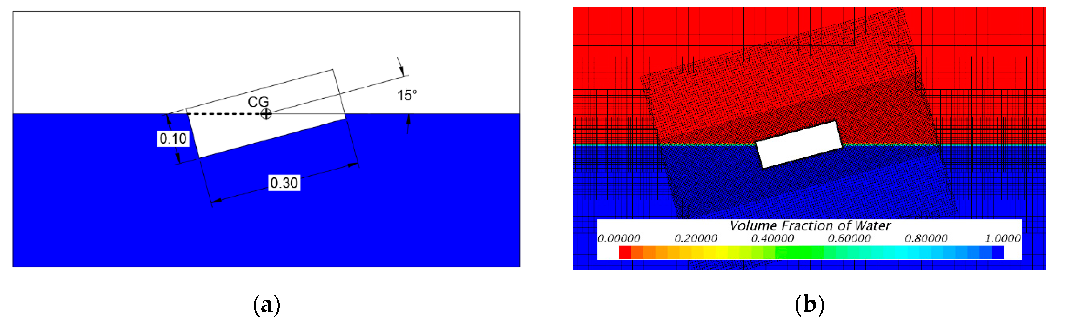
To validate the CFD tool used, a roll decay test of a rectangular barge was simulated and the results compared to the published experimental data by [6]. The simulation considered a 2-D barge 0.3 m wide, 0.1 m high, while the moment of inertia was and the density was . The barge was allowed to rotate freely to its center of gravity (CG). It was inclined at an initial roll angle of 15 with respect to the free surface. The draft was set at 0.05 m. Figure 1a shows the initial setup.
Only rolling motion was freely represented using multi blocks and overset grids while other motions were constrained. The inner grid was allowed to rotate while the outer grid remained static. The fine grid was used near the free surface as shown in Figure 1b. Second order schemes were used for convection and temporal terms. The y+ value is defined as a non-dimensional distance (based on local cell fluid velocity) from the wall to the first mesh node. Therefore, to guarantee the turbulence model was applied correctly in the numerical simulation a was used. The barge was discretized with a uniform grid near-body with spacing of 0.005 m and a Courant number (CFL) smaller than 1 was used during the simulation. Calderer et al. (2014) [11] used four grids with spacing of 0.008, 0.004, 0.002, and 0.001 m and a time step of 0.0005 s was employed. Calderer et al. (2014) performed LES simulations to study the vortex around the barge.
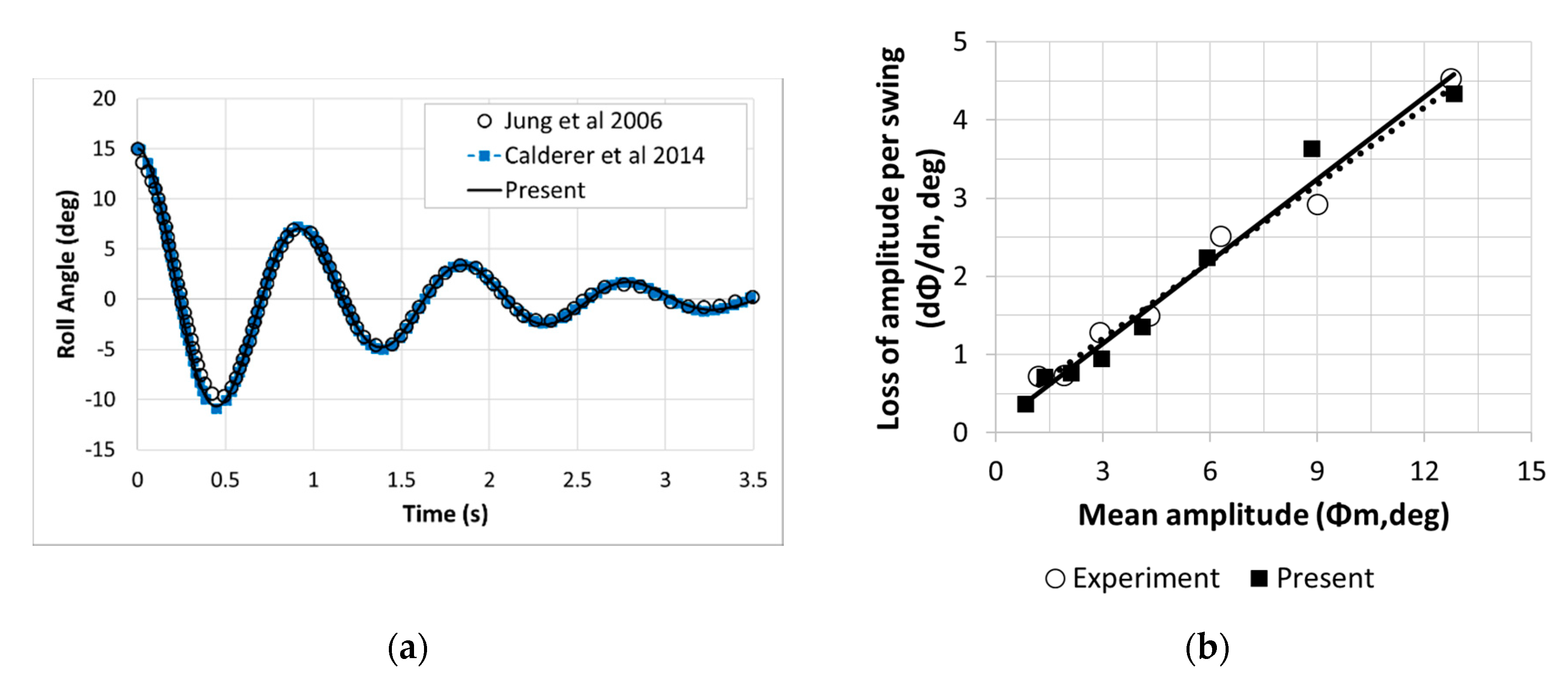
Figure 2a shows the results of roll decay test, that were compared with the experiment [6] and the other CFD simulation [11]. The natural period obtained from the simulation is , which is 0.945% different from the experiment (). Figure 2b shows the curve of extinction for the roll decay motion. The slope in the graph was used to calculate the damping coefficient following [12]. The damping coefficient calculated from the simulation results is 0.538 and shows an error of 3.68% compared to 0.519 in the experiment [6], which gives a very good agreement. Therefore, it can be seen that the present numerical schemes and mesh setting can be considered to be valid for the hull optimization to minimize roll motion and stability analysis related to the workability of 3-D vessels due to wake-wash effects.
2.2. Roll Decay Motion of Optimized W-Shape Hull
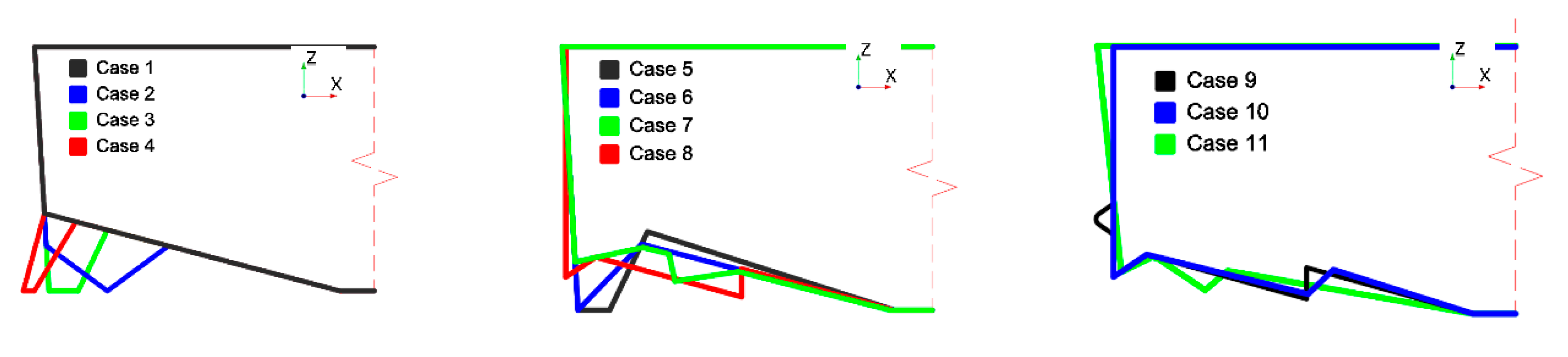
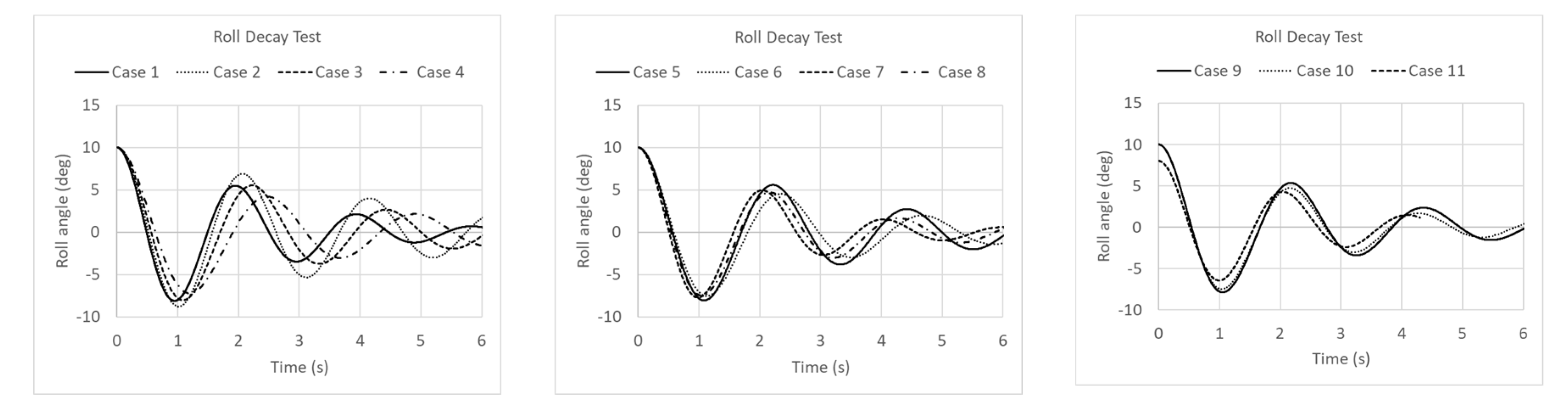
A series of roll decay motion for 11 hulls were simulated using the numerical schemes and grid system in the same manner of the prementioned validation case. Figure 3 illustrates the 11 hulls used in the optimization stage while Case 1 shows a common hull geometry for a seaweed harvesting boat. Proposed hull geometries (Cases 2–11) included appendages attached at the hull bottom based on different angles, length, and shapes to dissipate the rolling motion through vortex. Based on the hull geometry, physical properties of the hull were modified, for example, moment of inertia, draft, added mass, damping, and buoyancy force. Therefore, different approaches were considered to find the proper balance which can produce roll motion reduction. Cases 2, 3, 5, 6, and 8 considered big appendages, on the other hand, Cases 4, 7, 10, and 11 were based on short appendages which smoothly dissipate the roll motion. Results of roll motion for Cases 1–11 are shown in Section 3.1.
2.3. Workability of Boats by Wake-Wash
In order to investigate the workability of the optimized vessel through the previous process, the roll motion performance between the original and optimized vessels due to the influence of Kelvin waves generated by other vessels passing by (called as wake wash [13,14,15]) were compared. The portside force of the target boat was applied during the whole simulation to account for the situation in which the worker’s weight was biased to one side for the operation. Therefore, the simulation was conducted by inducing an initial roll angle at the beginning of the simulation and compared with the case where the workers were located in the center of the boat and no initial roll angle condition was generated.
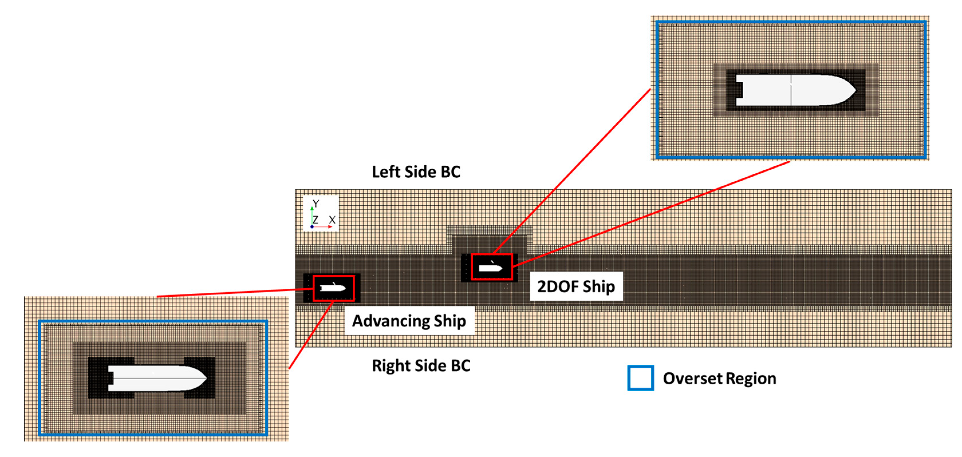
The target ship rotated freely around the x-axis (roll motion) while a passing ship advanced free in the x-direction (surge motion). The overset grid was introduced to allow surge and roll motions in advancing and target boat, respectively. Figure 4 shows the schematic view of grid system for initial setup and location of advancing and target boats.
Fine mesh was located around the free surface and waves near the Left and Right Side boundary conditions were damped to avoid wave reflection through introducing vertical resistance to the vertical motion. The advancing ship accelerated at 25 knots and the target ship rests at zero speed under working conditions. The original and W-shape hulls were located in turn at the target ship position, on the other hand, the original hull was used as the advancing ship for both simulations.
3. Simulation Results
3.1. Roll Decay Motion of Optimized W-Shape Hull
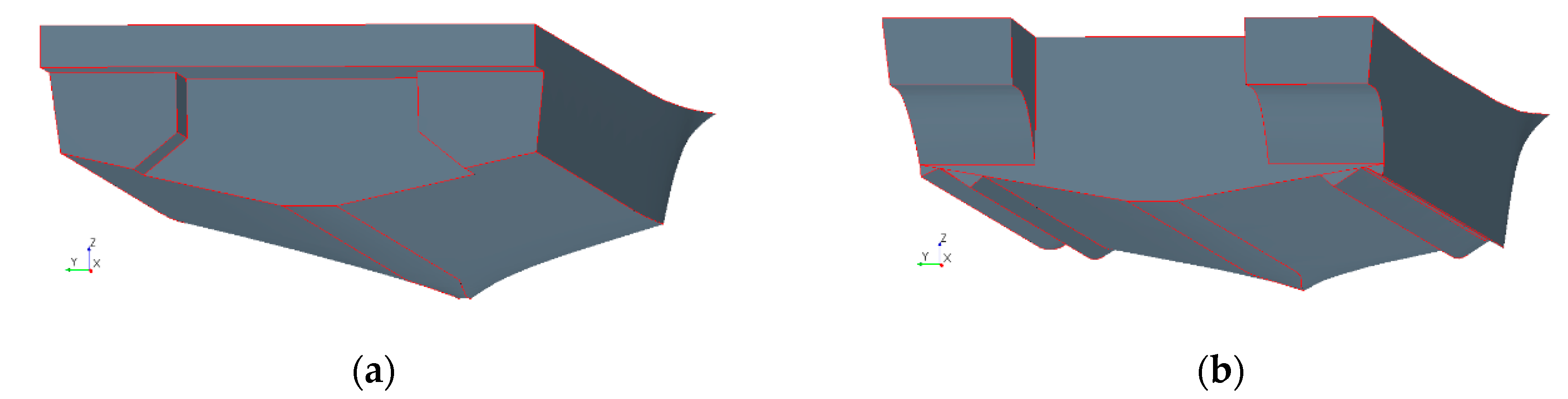
Figure 5 shows the roll motion results of the optimized shapes, hull geometries are shown in Figure 3. Roll motion of the original hull is presented in Figure 5 in Case 1, while results of investigated hulls are shown in Cases 2–11. Cases 2 and 5 increase the roll motion and natural period compared with the original hull. Cases 3, 7–10 showed similar performance to the original hull; however, time series of Case 3 showed a considerable increment of the natural period. Cases 4, 6, and 11 reduced roll motion compared with the Case 1. However, the natural period of Cases 4 and 6 are larger than 2 s which is larger than the original hull. Roll motion of Case 11 is considerably more damped compared with proposed hulls and original hull (Case 1). Due to natural period and decrement of roll motion, a 3-dimensional model of Case 11 was performed to study wake-wash effect. The original hull and optimized W-shape hull are shown in Figure 6, in which appendages at the optimized hull are attached on the hull bottom to increase the damping dissipation through vortex behavior.
3.2. Resistance Force and Effective Horsepower Calculation
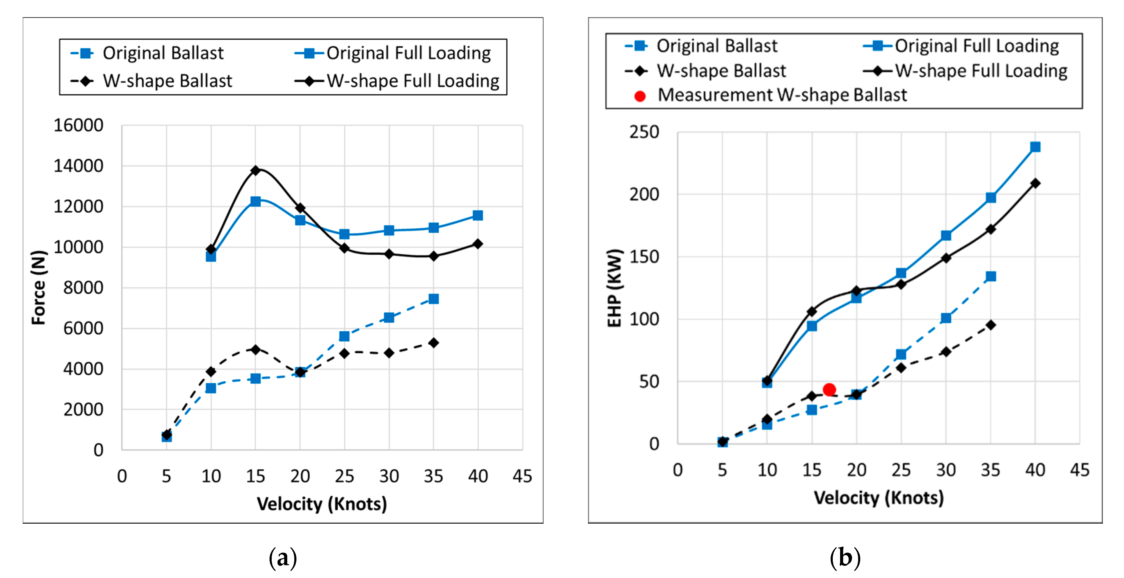
The resistance increased due to W-shape at the bottom of the hull. Therefore, resistance simulations at several incoming flow velocities (5–40 knots) were performed to verify the increment of the hydraulic force at the hull. Figure 7a shows a comparison of the resistant calculation for ballast (the boat is not loaded with seaweed) and full loading condition (the boat is loaded with 2 T of seaweed) of the original and W-shape hull. Results showed that the force augmented for flow velocities below 20 knots because the W-shape hull increases the submerged transversal area. However, above 20 knots the boat moved upwards and transversal area decreased inducing a reduced force.
The effective horsepower (EHP) was calculated based in the Equation (3) where stands for velocity in the x direction and stands for the resistance force as function of . Figure 7b shows the trends of ballast and full loading condition of original and W-shape hull. Fuel consumption is not seriously affected at 10 and 15 knots due to hull shape optimization and a motor of 150 KW can provide required power for design speed of 15 knots.
A full-scale boat, of which the principal dimension was 9.6 2.6 0.65 m, was built of aluminum material based in the W-Type hull and a sea trial was tested at 17 knots under the ballast condition. EHP was measured trough sea trial test, and the result was displayed in a red circle in Figure 7 and compared with the CFD estimation. Sea trial measurement agrees very well with simulation results.
3.3. Workability of Boats by Wake-Wash
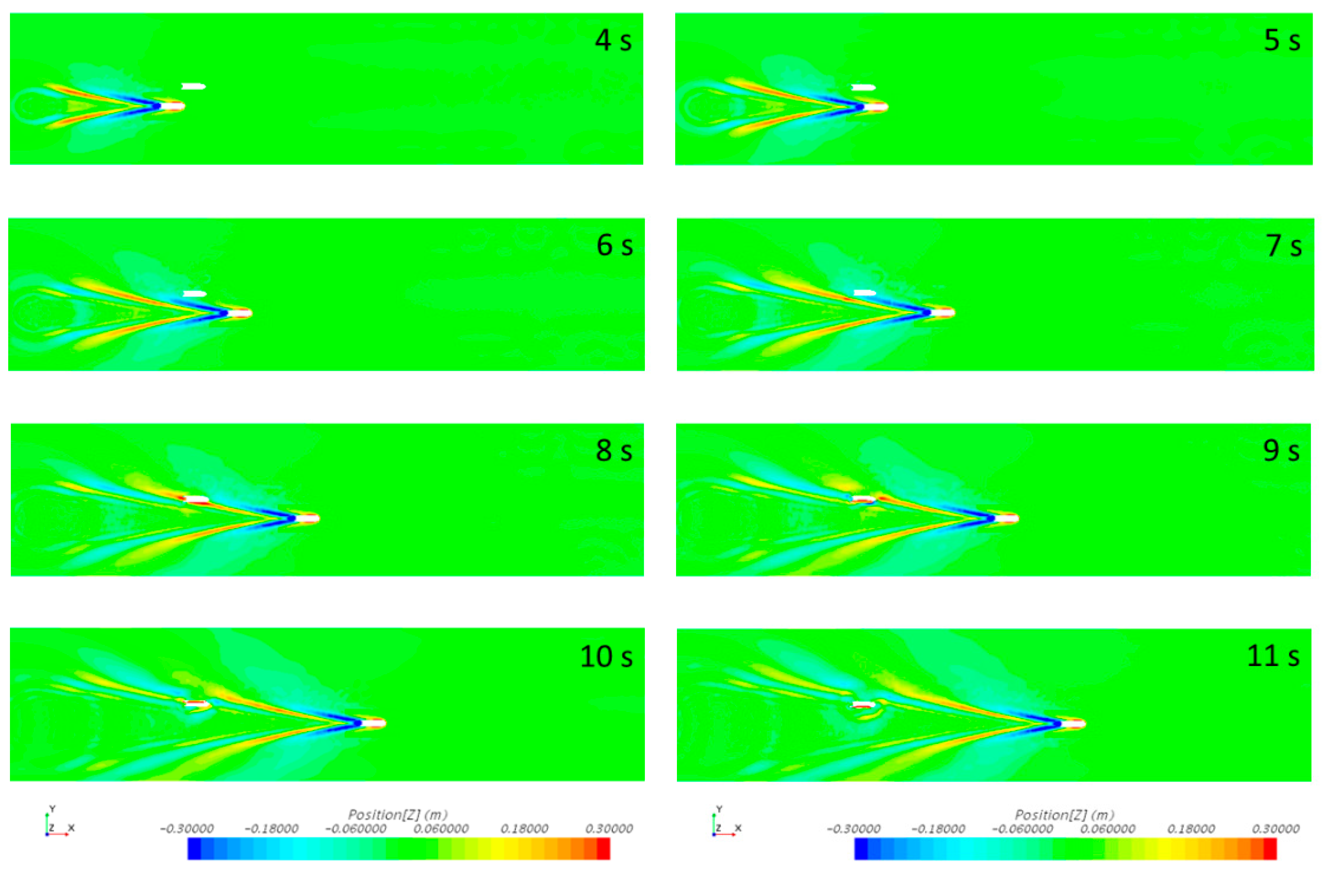
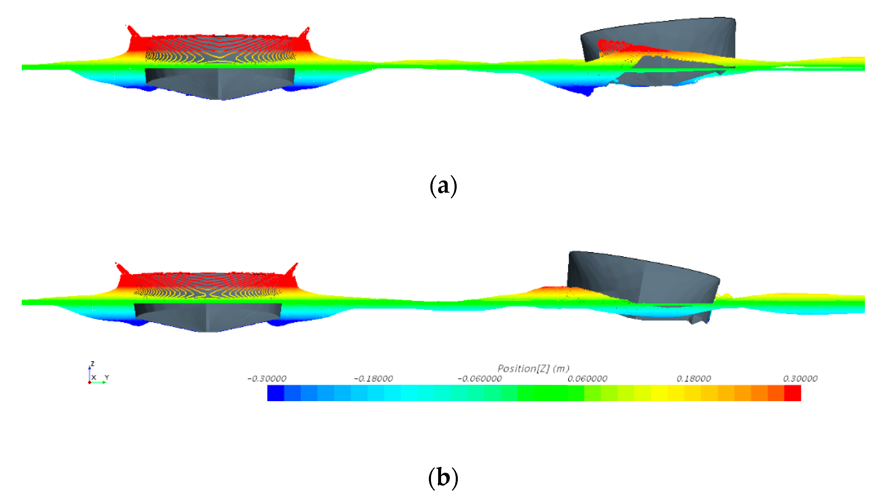
Figure 8 shows the Kelvin waves patterns of a passing ship at several time frames for the W-shape ship located at a target position. The Kelvin waves pull the target ship and rolls in starboard and portside. The roll motion goes to decay due to the radiation waves produced by the target ship, vortex generation, and W-shape hull form. The motion is described next. At t = 6 s, the wave trough pulls target ship into starboard. From t = 7 s to t = 8 s, the following wave crest approaches the rolling ship making it roll in the opposite direction (i.e., port side). The target ship rolls into the starboard again and the roll motion is augmented due to the incoming wave trough.
Figure 9a shows the frontal view of the advancing and target boats at t = 9 s where the maximum motion to the starboard can be observed. After t = 9 s the roll motion decays and the boat rolled into the portside again and approximately at t = 10 s, as it is shown in Figure 9b, the following wave crest hits the boat; however, the height of the wave crest is smaller than the previous wave trough. The subsequent wave crest and trough do not seem to influence significantly the roll motion of the target boat. Since then, roll motion of W-shape boat decays until the ship rests at zero roll angle.
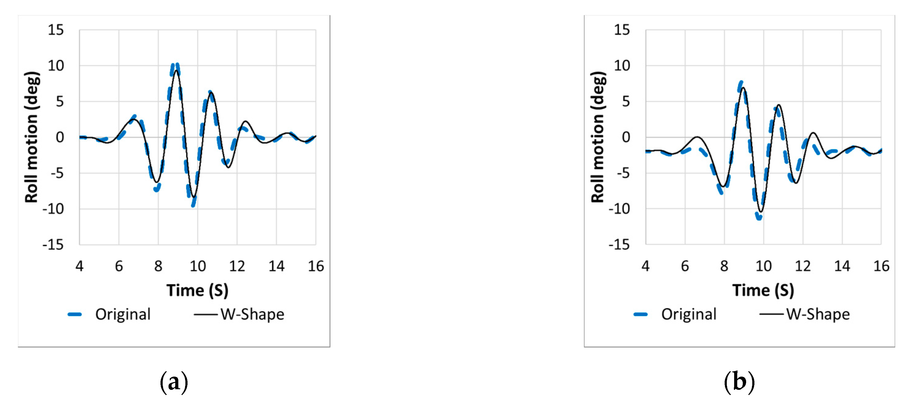
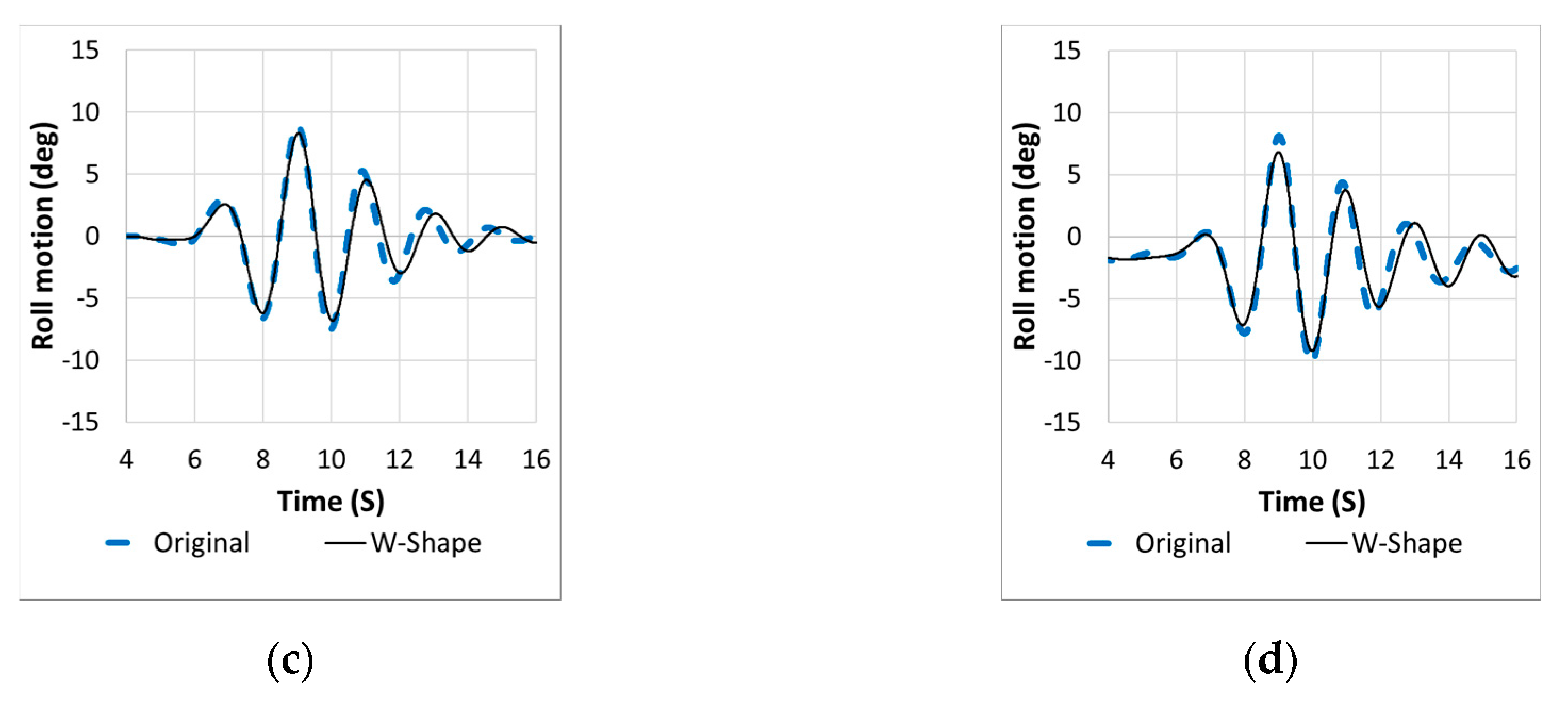
Figure 10 shows the roll motion of the original and W-shape boats under ballast and full loading conditions with and without an initial heel angle. The roll motion of the original and optimized hulls follows a similar trend when the starboard of hulls is impacted by the crest and trough of Kelvin waves produced by the passing boat. Figure 10a,c demonstrates the differences between ballast and full loading condition and it can be concluded that the motion is smaller during full loading condition as the center of gravity is lower than ballast condition. The largest roll motion can be observed in Figure 10b under ballast condition with an initial heel angle. The maximum roll motion of the original boat is greater than 10. On the other hand, the W-shape boat shows the maximum motion smaller than 10° which shows the effectiveness of this type of hull form to reduce the roll motion during wake-wash condition.
Table 1 shows a comparison of the maximum roll motion for wake-wash simulations. Percentage reduction was calculated based on the difference of the original hull with W-Type hull divided by the maximum roll angle of original hull. It clearly observed a reduction of the maximum roll motion especially in full loading condition by reduction of 16.31. W-Type hull definitely reduced the roll motion in wake wash condition.
4. Conclusions
The purpose of this paper was to optimize a hull to reduce the roll motion due to the Kelvin waves produced by another vessel passing by. The hull was modified using a W-shape, based on a standard (original) hull which is used to harvest seaweed. The present study was performed based on numerical simulation. Therefore, algorithm (PISO), numerical schemes, and technique (DFBI) were tested and the results of mentioned numerical schemes were validated with experimental results [3].
The numerical method used in the validation case was used to simulate the roll motion of 11 modified hulls based on a 2-D model. The modified hull in which the motion decay was quicker (case 11) was used to generate a 3-D model. The 3-D model was used to calculate the increment of the hydraulic force due to the optimization of the hull and EHP. Resistance force and EHP were compared with a sea trial of a built boat. The sea trial measurement agreed very well with the simulation results. In addition, the 3-D model was used to study and to compare the roll motion for the original and optimized seaweed hull under wake wash produced by a passing ship. In addition, ballast and full loading conditions were compared for the original and the W-shape hulls. The advancing boat produced Kelvin waves which produced a roll motion in the boat located at the target position. The Kelvin waves pull the target ship and it rolls in starboard and portside. After the maximum roll motion toward the starboard was reached (t = 9 s) the roll motion decayed due to the radiated waves produced by the target ship.
Time series of roll motion was studied for ballast and full loading condition of original and optimized hull. The weight of the workers was located at the center and towards one side of the boat during working hours (initial heel angle). Based on the numerical simulation results, roll motion is smaller for full loading condition as the center of gravity is lower than in the ballast condition. The larger roll motion was observed under ballast condition with an initial heel angle. The optimized W-shape reduced the roll motion with an initial heel angle. The original roll angle was greater than 10 while the roll motion was below 10 for the W-shape. Reduction of roll motion was clearly observed by comparison of the maximum roll angle. In no initial heel angle case, the maximum reduction in terms of roll motion reduction was observed during ballast condition with a reduction of 1.24. The effectiveness of the W-shape is clearly observed under full loading condition with initial heel angle where a reduction of 1.32 (16.31%) was observed in comparison with the original hull. Roll motion of optimized hull was reduced due to the W-shape demonstrating the effectiveness of the W-shape to decrease roll motion in ballast and full loading condition considering a lateral change of the center of gravity due to the worker’s weight.
Author Contributions
Conceptualization, J.-C.P.; Data curation, D.-H.K.; Formal analysis, M.P.E.H.; Funding acquisition, S.-B.L.; Resources, J.-C.P.; Supervision, J.-C.P.; Writing—original draft, M.P.E.H.; Writing—review and editing, J.-C.P. All authors have read and agreed to the published version of the manuscript.
Funding
This research was a part of the project titled ‘Development of coastal garbage collection technology in difficult to access areas’, funded by the Ministry of Oceans and Fisheries, Korea.
Conflicts of Interest
The authors declare no conflict of interest.
References
- Ferdouse, F.; Holdt, F.; Smith, S.L.R.; Murúa, P.; Yang, Z. The Global Status of Seaweed Production, Trade and Utilization; Food and Agriculture Organization of the United Nations: Rome, Italy, 19 November 2018. [Google Scholar]
- Bellafiore, D.; Zaggia, L.; Broglia, R.; Ferrarin, C.; Barbariol, F.; Zaghi, S.; Lorenzetti, G.; Manfe, G.; De Pascalis, F.; Benetazzo, A. Modeling ship-induced waves in shallow water systems: The Venice experiment. Ocean. Eng. 2018, 155, 227–239. [Google Scholar] [CrossRef]
- Ghani, M.P.A.; Rahim, M.A.R.M.A. The prediction of wake wash in the towing tank. J. Mek. 2008, 26, 129–140. [Google Scholar]
- Gu, Y.; Day, S.; Boulougouris, E. A Study on the Effects of Bilge Keels on Roll Damping Coefficient. In Proceedings of the 12th International Conference on the Stability of Ships and Ocean Vehicles, Glasgow, UK, 14–19 June 2015. [Google Scholar]
- Shi, F.; Malej, M.; Smith, J.M.; Kirby, J.T. Breaking of ship bores in a Boussinesq-type ship-wake model. Coast. Eng. 2018, 132, 1–12. [Google Scholar] [CrossRef]
- Jung, K.H.; Chang, K.A.; Jae, J.H. Viscous Effect on the Roll Motion of a Rectangular Structure. J. Eng. Mech. 2006, 132, 190–200. [Google Scholar] [CrossRef]
- SIEMENS. STAR-CCM+ User Guide; Version 11.06; SIEMENS: Munich, Germany, 2016. [Google Scholar]
- Menter, F.R.; Kuntz, M.; Langtry, R. Ten Years of Industrial Experience with the SST Turbulence Model. In Turbulence, Heat and Mass Transfer; Hanjalić, K., Nagano, Y., Tummers, M., Eds.; Begell House Inc.: New York, NY, USA, 2003; pp. 625–632. [Google Scholar]
- Wilcox, D.C. Turbulence Modeling for CFD, 2nd ed.; DCW Industries Inc.: La Canada Flintridge, CA, USA, 1998; pp. 172–180. [Google Scholar]
- Caponnetto, M.; Bučan, B.; Pedišić-Buča, M.; Perić, M.; Pettinelli, C. Simulation of Flow and Motion of High-Speed Vessels. In Proceedings of the 12th International Conference on Fast Sea Transportation, Amsterdam, The Netherlands, 2 December 2013. [Google Scholar]
- Calderer, A.; Kang, S.; Sotiropoulos, F. Level set immersed boundary method for coupled simulation of air/water interaction with complex floating structures. J. Comput. Phys. 2014, 277, 201–227. [Google Scholar] [CrossRef] [Green Version]
- Bhattacharyya, R. Dynamics of Marine Vehicles; Wiley: New York, NY, USA, 1978. [Google Scholar]
- Stumbo, S.; Fox, K.; Dvorak, F.; Elliot, L. The Prediction, Measurement, and Analysis of Wake Wash from Marine Vessels. Mar. Technol. 1999, 36, 248–260. [Google Scholar]
- Garel, E.; Fernández, L.L.; Collins, M. Sediment resuspension events induced by the wake wash of deep-draft vessels. Geo-Mar. Lett. 2008, 28, 205–211. [Google Scholar] [CrossRef]
- Osborne, P.D.; McDonald, N.J.; Reynolds, W.J. Response of mixed sediment beaches to wake wash from passenger only fast ferries: Rich Passage, Washington. In Coastal Engineering 2006; Smith, J.M., Ed.; World Scientific: Singapore, 2007; Volume 5, pp. 3105–3116. [Google Scholar]
Figure 1.
Roll decay test of 2-D rectangular barge used for validation. (a) Dimensions of barge; (b) overset grid system.
Figure 1.
Roll decay test of 2-D rectangular barge used for validation. (a) Dimensions of barge; (b) overset grid system.

Figure 2.
Results of verification condition. (a) Roll decay motion; (b) extinction curve.

Figure 3.
Geometry of proposed W-shape hulls.

Figure 4.
Schematic view of initial setup and location of advancing and target boats.

Figure 5.
Roll decay results of proposed W-shape hulls.

Figure 6.
3-dimensional view of original and optimized hulls. (a) Original boat; (b) W-shape boat.

Figure 7.
Resistance and effective horsepower. (a) Resistance force calculation (N); (b) effective horsepower (KW).
Figure 7.
Resistance and effective horsepower. (a) Resistance force calculation (N); (b) effective horsepower (KW).

Figure 8.
Wave patterns around advancing and target ships.

Figure 9.
Influence of wave trough (upper) and crest (lower) on W-shape boat in ballast condition. Advancing boat is located at the left side and W-Shape hull is located at the right side of the figure. (a) time = 9 s; (b) time = 10 s.
Figure 9.
Influence of wave trough (upper) and crest (lower) on W-shape boat in ballast condition. Advancing boat is located at the left side and W-Shape hull is located at the right side of the figure. (a) time = 9 s; (b) time = 10 s.

Figure 10.
Roll motions in ballast conditions (a) w/o initial heel angle; (b) w/initial heel angle; and in full loading conditions (c) w/o initial heel angle (d) w/initial heel angle.
Figure 10.
Roll motions in ballast conditions (a) w/o initial heel angle; (b) w/initial heel angle; and in full loading conditions (c) w/o initial heel angle (d) w/initial heel angle.


Table 1.
Comparison of maximum roll motion.
| Initial Heel | Condition | Hull Type | Max Roll Motion (Deg) | Reduction (Deg) | Reduction (%) |
|---|---|---|---|---|---|
| No initial heel angle | Ballast | Original | 10.54 | 1.24 | 11.76 |
| W-Type | 9.30 | ||||
| Full loading | Original | 7.91 | 0.99 | 12.57 | |
| W-Type | 6.91 | ||||
| Initial heel angle | Ballast | Original | 8.72 | 0.50 | 5.69 |
| W-Type | 8.22 | ||||
| Full loading | Original | 8.11 | 1.32 | 16.31 | |
| W-Type | 6.78 |
© 2020 by the authors. Licensee MDPI, Basel, Switzerland. This article is an open access article distributed under the terms and conditions of the Creative Commons Attribution (CC BY) license (http://creativecommons.org/licenses/by/4.0/).
Share and Cite
MDPI and ACS Style
Haro, M.P.E.; Park, J.-C.; Kim, D.-H.; Lee, S.-B. CFD Simulation on Workability of a Seaweed Harvesting Boat Due to Wake-Wash. J. Mar. Sci. Eng. 2020, 8, 544. https://doi.org/10.3390/jmse8080544
AMA Style
Haro MPE, Park J-C, Kim D-H, Lee S-B. CFD Simulation on Workability of a Seaweed Harvesting Boat Due to Wake-Wash. Journal of Marine Science and Engineering. 2020; 8(8):544. https://doi.org/10.3390/jmse8080544
Chicago/Turabian StyleHaro, Marco Polo Espinoza, Jong-Chun Park, Dong-Hyun Kim, and Sung-Bum Lee. 2020. "CFD Simulation on Workability of a Seaweed Harvesting Boat Due to Wake-Wash" Journal of Marine Science and Engineering 8, no. 8: 544. https://doi.org/10.3390/jmse8080544
Note that from the first issue of 2016, this journal uses article numbers instead of page numbers. See further details here.