

Abstract
Non-collinear spin density functional theory calculations were employed to study structural, magnetic, and electronic properties of the hexagonal LuMnO3 compound in its ferroelectric phase. For that purpose, it was utilized full-potential linearized augmented plane wave plus local orbitals method, for the first time. The exchange and correlation effects were treated in the frame of the local spin density approximation (LSDA) including effective Hubbard (Ueff) correction. The principal objective of the work was to determine three properties of the LuMnO3 ground state: (1) the crystallographic space group (P63cm or P63), (2) the non-collinear magnetic configuration of the Mn spin moments (Γ1, Γ2, Γ3, Γ4, Γ1 + Γ2 or Γ3 + Γ4), and (3) the electronic structure. The results reveal that the P63cm structure with the Γ3 + Γ4 spin configuration (with ϕ = 80°) should be the ground state. The calculated indirect bandgap of 1.19 eV agrees well with the gap determined from optical conductivity measurements. Analysis of the details of the calculated electronic structure made it possible to interpret the origin of the most pronounced 1.7 eV peak in the optical conductivity spectrum, as well as to explain why it is registered only for the incident light polarized perpendicularly to the c-axis.
Export citation and abstract BibTeX RIS
1. Introduction
The hexagonal LuMnO3 compound in its ferroelectric phase (space group P63cm) has been extensively investigated because it exhibits both magnetoelectric [1–3] and magnetoelastic effects [4–6]. Moreover, LuMnO3 is an interesting material for application in ferroelectric photovoltaic devices [7]. The magnetoelectric effect, which manifests itself as a coupling between magnetism and ferroelectricity, has drawn the attention of the scientific community because of its technological significance in controlling one order parameter through the other. In the LuMnO3, magnetic and electric orders coexist below ∼90 K [3, 8]. The magnetism is due to the Mn3+ ions whose spin magnetic moments are arranged in a non-collinear triangular manner within the hexagonal basal planes. On the other hand, the ferroelectric order arises due to the asymmetric movement of Lu3+ ions (along the c-axis) from their positions in a corresponding high-temperature centrosymmetric structure (space group P63/mmc). The most probable reason for this movement is found to be a re-hybridization between empty Lu dz2 and populated O pz orbitals along the c-axis [9–11].
Although the structural and magnetic properties of the LuMnO3 in the ferroelectric phase have been investigated in numerous experimental and theoretical studies up to now, a few important questions remained unanswered, still provoking the debate in the literature.
One of these questions refers to the crystallographic space group (CSG) of the LuMnO3 compound below the Néel temperature (TN). Despite many experimental works had described LuMnO3 as having the CSG P63cm [3–5, 7–9], Tong et al [12] found that CSG P63 better characterizes the compound for the temperatures below TN. The two crystal structures are very similar globally, with slight differences in local surroundings around the Mn and Lu ions (figure 1). In both structures, the Mn ions are crystallographically equivalent and form the triangular lattices within the basal (a-b) hexagonal planes. These lattices are separated by c/2 along the c-axis, and rotated by 60 degrees around it with respect to each other. Each Mn is surrounded by five O ions, forming the trigonal bipyramid with the Mn in its center and the oxygens at its vertices. Two O ions (O1 and O2) are settled at the apical positions, approximately along the c-axis, and three of them at the in-plane positions, approximately within the basal plane (O3 and two O4 in the case of the P63cm, and O3, O4, O5 in the case of P63). Lower symmetry of the P63 CSG causes the splitting of the two equivalent ions (O4) into two inequivalent ones (O4 and O5). For both P63cm and P63 symmetries, there is one Lu1 and one Lu2 atom. However, in the P63 the site occupied by Lu2 is split into two (Lu2 and Lu3). All the Lu atoms are coordinated to eight O atoms (two apical and six equatorial). For the reason of clarity, these local structures are not presented in figure 1. The interested reader may, however, analyze the complete crystal structures and compare interatomic angles and distances based on crystallographic data recorded upon the LuMnO3 P63cm [4] and the P63 [12] structures, and using some visualization software.
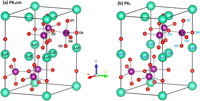
Figure 1. Conventional unit cells of the hexagonal LuMnO3 compound assuming (a) the P63cm crystal structure, as determined in [4], and (2) the P63 crystal structure, as determined in [12].
Download figure:
Standard image High-resolution imageAnother issue debated in the literature refers to the LuMnO3 ground state magnetic structure. Figure 2 shows the possible magnetic arrangements of the Mn spins for both P63 and P63cm CSG (actually, the P63cm permits two more arrangements [13] (not shown in figure 2) but, since they have not been indicated to be the ground states by the previous studies, they were not considered in the present work). Magnetic arrangements are distinguished by the angle ϕ, defined as the angle between the Mn spin direction and the a- or b-axis within the hexagonal basal plane. ϕ can be 0° (Γ2, Γ3), 90° (Γ1, Γ4) or 0°< ϕ < 90° (Γ1 + Γ2, Γ3 + Γ4).
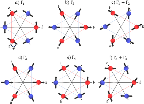
Figure 2. Symmetry allowed magnetic configurations of the Mn spins in the LuMnO3 compound, denoted by their irreducible representations (Γ1, Γ2, Γ3, and Γ4) and combination of them (Γ1 + Γ2 and Γ3 + Γ4). Arrows indicate the spin directions of the Mn atoms situated within the adjacent basal planes in the hexagonal unit cell (red and blue circles, respectively), separated by c/2 along the c-axis. The inter-plane coupling of the Mn moments is antiferromagnetic for the configurations (a)–(c), and ferromagnetic for the configurations (d)–(f).
Download figure:
Standard image High-resolution imageAs summarized in table 1, independent experimental and theoretical works have proposed different ground state magnetic configurations [2, 5, 10, 14–18]. The principal difficulty to resolve them, faced by experimentalists that employed the neutron diffraction method, is imposed by the existence of the so-called homometric spin configurations and limited instrumental resolution [5]. On the other hand, from a theoretical point of view (Density Functional Theory (DFT) and Hartree–Fock (HF) method), the obtained results were not decisive up to now mostly because the total energy difference between these magnetic structures is quite small (of the order of 10–4 eV). The co-existence of various magnetic structures in the LuMnO3 ground state could be an intrinsic characteristic of the system, but before concluding this, it is desirable to perform more investigations using different methodologies.
Table 1. Ground-state magnetic structure of the hexagonal LuMnO3 as determined in previous publications. DFT: density-functional theory; ND: neutron diffraction; SHG: second harmonic generation; HF: Hartree–Fock. The authors of the [16] concluded that the ground state magnetic configuration should be the Γ3 + Γ4 with ϕ = 80°.
| References | Method | Magnetic Configuration | |
|---|---|---|---|
| Experimental | |||
| [5] | ND | Γ4 | |
| [14] | SHG | Γ3 and Γ3 + Γ4 | |
| [15] | ND | Γ2 | |
| [16] | ND | Γ3 + Γ4 | |
| [17] | ND | Γ4 | |
| Theory | |||
| [2] | DFT | Γ3 | |
| [10] | DFT | Γ4 | |
| [18] | HF | Γ4 | |
The present work has an intention to elucidate the unresolved questions raised above, contributing to a better understanding of the low-temperature characteristics of important LuMnO3 multiferroic. Specifically, our objective is to determine the CSG and the magnetic structure of its ground state. Towards this objective, we performed a series of non-collinear spin DFT calculations [19, 20] utilizing for the first time the full-potential linearized augmented plane wave plus local orbitals (FP-LAPW+lo) electronic structure method [21, 22]. This method treats explicitly all atomic electrons (core + valence), while the previously reported DFT studies [2, 10], based on the pseudo-potential approach, approximate the potential of the core ones. Exchange and correlation effects were calculated in the frame of the LSDA + Ueff scheme [23, 24], as well as the previous DFT studies [2, 10]. The results demonstrated that the ground states should be characterized by the CSG P63cm with the Γ3 + Γ4 spin configuration (with ϕ = 80°). These conclusions are in accordance with the experimental observations published in [16]. The electronic structure has been calculated for the first time for this specific CSG and magnetic configuration. The calculated band gap value agrees with that determined from optical conductivity measurements [1], and the analysis of the partial density of states revealed the origin of the 1.7 eV peak observed in the optical spectrum for light polarized perpendicularly to the c-axis [1].
2. Computational method and details of calculations
All calculations have been performed by the all-electron FP-LAPW+lo method [21, 22], based on spin DFT [19] and implemented in the Elk (version 4.3.6) computer code [25]. In this method, the electronic wave functions, charge density, and crystal potential are expanded in spherical harmonics inside the non-overlapping spheres centered at each nuclear position (atomic spheres), and in-plane waves in the rest of the space (interstitial region). All electrons are treated explicitly: the valence ones by a self-consistent solution of the scalar-relativistic Kohn–Sham equation, while the core ones are relaxed in a fully-relativistic way [26]. For both investigated crystal structures (P63cm and P63) the same computational parameters have been utilized. Atomic sphere radii (RMT) chosen for the Lu, Mn, and O atoms are shown in table 2, as well as the electron states that have been considered as valence ones. Inside the atomic spheres, the expansion of the partial waves was limited to lmax = 10. In the interstitial region, the number of plane waves was defined by the cut-off at Kmax = 7.0/RMT(O), where RMT(O) is the oxygen atomic sphere radius. Charge density was Fourier expanded up to Gmax = 16. For the Brillouin zone integration, it was used a 4 × 4 × 2 k-point grid. The effects of the spin–orbit coupling have been calculated via a second variational procedure which utilizes scalar-relativistic eigenfunctions as a basis set [26].
Table 2. Atomic sphere radii (RMT, expressed in atomic units) and valence states that were adopted in the present calculations of the properties of the LuMnO3 assuming either P63cm or P63 crystal structure.
| Atom | RMT (a. u.) | Valence states |
|---|---|---|
| 71Lu | 2.1 | 5s25p64f145d16s2 |
| 25Mn | 1.8 | 3s23p63d54s2 |
| 8O | 1.5 | 2s22p4 |
All six non-collinear magnetic structures shown in figure 2 have been simulated, for both crystal structures P63cm and P63. For the lattice parameters and atomic positions, we have adopted the experimentally determined ones at T = 10 K [4] (P63cm) and T = 12 K [12] (P63), respectively. Spin arrangement for each of the six simulated magnetic structures has been initially set up by switching on an external magnetic field inside the Mn atomic spheres, pointed to the directions which precisely define it. Then, during the self-consistent calculation, this field was gradually switched off [25]. This procedure guaranteed that the magnitude and the direction of the Mn spin moments were not fixed, but allowed to change. The self-consistent calculations upon all magnetic and crystal structures have been performed in an equal way (using the same computational parameters) and on the same level of precision. They successfully converged within the energy precision of 10–5 Ha. For Γ1 + Γ2 and Γ3 + Γ4 configurations, the initial value of the angle ϕ was set up to be 80°, as being indicated by experiment [16].
Exchange and correlation (XC) effects have been treated by local spin density approximation (LSDA) with effective Hubbard correction term (Ueff) (LSDA + Ueff) [23, 24]. The Hubbard correction has been employed to correct the size of the bandgap since the standard LSDA approach severely underestimates it. The LSDA + Ueff approach is based on Hubbard multiband model, in which the parameters U and J approximate correlation and exchange effects between the Mn d-electrons, respectively. The values for the U and J were chosen to be the same as utilized in recent DFT calculations upon the YMnO3 compound [27] (U = 3.5 eV and J = 0.95 eV, resulting in Ueff = U- J = 2.55 eV). This choice has been made because Ueff = 2.55 eV reproduced the YMnO3 dielectric tensor in excellent agreement with the experimental data [28]. As will be shown in section 3.2, this Ueff successfully reproduces the bandgap of the LuMnO3 determined from optical conductivity measurements.
3. Results and discussion
3.1. The crystal structure and magnetic configuration of the ground state
Figure 3 compares the computed total energies of the hexagonal LuMnO3 in different magnetic configurations simulated upon CSG P63 and P63cm. Independently of the spin arrangement, the CSG P63cm is energetically more favorable than P63. Thus, the present results do not confirm the conclusions of Tong et al [12] who suggested the lowering of the symmetry of the LuMnO3, from P63cm to P63, below the Néel temperature, but corroborate with the conclusions of various other works which describe the LuMnO3 in its ferroelectric phase with CSG P63cm [3–5, 7–9, 16].
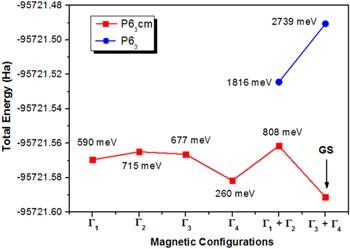
Figure 3. Total energies (in Hartree) of different magnetic configurations of the LuMnO3 compound in its CSG P63cm and P63. The abbreviation GS means the 'ground state'. For each magnetic configuration, it is presented the difference of its total energy with respect to the total energy of the GS, expressed in millielectron-volt (meV).
Download figure:
Standard image High-resolution imageIt is interesting to observe that for the CSG P63cm, all six magnetic structures shown in figure 2 successfully converged. For the CSG P63, this was the case only for Γ1 + Γ2 and Γ3 + Γ4 configurations. The initially set Γ1 and Γ4 structures converged to the spin configurations with a non-zero canting angle, which is not permitted by symmetry. Γ2 and Γ3 converged to the configurations with ϕ ≠ 0, which does not characterize them. For all four obtained structures, the total energies were found to be higher than Γ3 + Γ4 spin configurations. The possible reason for this failure could be the local distortion around the Mn atoms in relation to the CSG P63cm (compare figures 1(a) and (b)), which does not favor the stabilization of the Γ1, Γ2, Γ3, or Γ4 magnetic spin configurations. To elucidate this fact, a detailed analysis of interlayer super-exchange interaction and the single-ion anisotropy should be performed. As it was discussed in [2, 18], the interlayer super-exchange interaction should be responsible for distinguishing the inter-plane coupling (ferromagnetic or antiferromagnetic) while the single-ion anisotropy should be responsible for determining the Mn moment direction (ϕ angle) within the a-b crystalline plane.
According to figure 3, the Γ3 + Γ4 (with ϕ = 80°) should be the ground state magnetic structure of the LuMnO3. This result agrees with the experimental prediction made by Park et al [16]. It is interesting to note that our previous theoretical results about the ground state magnetic structure of the hexagonal YMnO3 compound [29] also agree with the conclusions of Park et al [30]. In this latter case, the ground-state magnetic structure of the hexagonal YMnO3 was found to be Γ1 + Γ2 (with ϕ = 10°). The ϕ = 80° was an initial guess in our calculations, but, despite the ϕ was allowed to change in the course of calculations, it persisted with this value until the end of the convergence. This means that ϕ = 80° is found to be energetically favorable for both Γ1 + Γ2 and Γ3 + Γ4 magnetic configurations. It is important to mention that, in comparison with the previous DFT [2, 10] and HF [18] calculations, the energy differences between the considered magnetic structures are much higher (hundreds of meV). Previously reported energy differences are of the order of 10−5 eV [2, 10] and 10−8 eV [18].
The Γ3 + Γ4 magnetic configuration is characterized by a small canting of the spins out of the a-b plane ( = 0.002 μB/Mn-atom), which, however, results in a zero magnetization since the z-components of the spin moments in adjacent a-b planes cancel each other. The computed value for
  is of the same order of magnitude as that measured for the hexagonal ScMnO3 compound (0.009 μB/Mn-atom) [13]. Park et al [16] have not measured
  for the LuMnO3 compound. The calculated non-zero
  value arises entirely from the spin–orbit coupling of the Mn d-electrons since no external field along the c-axis has been applied in the course of the calculations. The spin magnetic moment of the Mn ions was computed to be 2.91 μB/Mn-atom, a value that fits within the interval of the experimental predictions (2.48 (5) μB/Mn-atom [15] and 3.3 μB/Mn-atom [16]). Previous theoretical studies [2, 10, 18] did not present the results for the spin magnetic moment of the Mn ion.
The present result for the ground state magnetic structure of the LuMnO3 is in accordance with the conclusions of Fabreges et al [31], who connected this property of the hexagonal manganites RMnO3 with the internal parameter  which determines the Mn position. According to their analysis based on spin-lattice coupling, the
  should favor ferromagnetic coupling between the Mn planes, and the magnetic structure tends to be Γ3 or Γ4, while the
  should favor antiferromagnetic coupling between the Mn planes with the magnetic structure either Γ1 or Γ2. In present calculations, the Mn position is determined by
 and the ground state magnetic structure is found to be Γ3 + Γ4. It is interesting to mention that our earlier DFT study of YMnO3 [29] indicated Γ1 + Γ2 configuration as the ground state magnetic structure (with a very small energy difference in relation to Γ3 + Γ4). In these calculations, the Mn position was determined by
  (
( ). Thus, the calculated ground state magnetic structures of LuMnO3 and YMnO3 agree with the fact that these compounds have different natures of the interplane couplings.
3.2. Electronic structure of the ground state
Figure 4 presents the band structure of the hexagonal LuMnO3 in its ground state (CSG P63cm with magnetic configuration Γ3 + Γ4) calculated along the certain high symmetry directions in the Brillouin zone. As shown in this figure, the compound is characterized by an indirect bandgap of 1.19 eV (M → Γ) and a direct bandgap of 1.29 eV (Γ → Γ). The characteristics of the band structure and the bandgap are found to be the same for both of the CSG (P63cm and P63) and all six simulated magnetic structures. Present results are different in relation to the results from previous DFT studies [2, 7]. In the [2], the authors reported the bandgap of 1.43 eV, but it has been calculated upon the collinear configuration of the Mn spins. As the band structure has not been presented, it is unclear if this gap has direct or indirect character. In the [7], the authors reported an indirect bandgap of 1.45 eV (M → Γ) and a direct bandgap of 1.48 eV (Γ → Γ), as well as the different band dispersion on the top of the valence band. They, however, did not report upon which magnetic configuration the calculations have been performed. Additionally, they utilized very different Ueff value (Ueff = 8.0 eV) in relation to the present study.
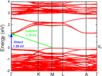
Figure 4. Band structure of the hexagonal LuMnO3 compound in its ground state (CSG P63cm and Γ3 + Γ4 magnetic structure). EF denotes the Fermi level.
Download figure:
Standard image High-resolution imageFrom the experimental point of view, the energy bandgap of the LuMnO3 has been estimated to be 1.1 eV [1] and 1.555 ± 0.025 eV [7]. The discrepant results may be related to the form of the sample that the authors utilized in their experiments. In [1], the energy bandgap was determined from optical absorption measurements performed upon single-crystal samples, while in the [7] the measurements were performed upon thin-film samples. In the latter case, the thickness of the film could have an influence on the band gap value of the material [32]. Considering this fact, as well as the fact that our calculations describe the bulk properties of the material, the comparison with the result presented in [1] is more appropriate. Thus, we can conclude that the calculated bandgap value agrees very well with the experimental one [1]. This agreement serves as a reliable manner to validate the value of the Ueff = 2.55 eV, used in this work, giving credibility to other presented results.
In figure 5, it is presented the calculated density of electronic states (DOS) of the LuMnO3 compound in its ground state. In the chart at the top, it is shown the total DOS of the compound. The charts below it exhibit the partial DOS (PDOS) of the Lu and the Mn ions, as well as the O ions which surround the Mn ion (see figure 1(a)). As a representative of the Lu ions, it is chosen Lu1 (Lu2 exhibits very similar PDOS). Considering the O ions, they are distinguished according to their location in the Mn neighborhood. As a representative of apical oxygens (Oapical), it is chosen O1 (O2 exhibits very similar PDOS), while the oxygens situated (approximately) within the basal plane (Oin-plane) are represented by O4 (with very similar PDOS as O3).

Figure 5. Top chart: the calculated total density of states (DOS) (in states per eV and per unit cell) of the LuMnO3 in its ground state (CSG P63cm and Γ3 + Γ4 magnetic structure). The charts below: the partial DOS (in states per eV and per atom) of the Mn, the Lu, and the oxygens located in the first neighborhood of the Mn. As representatives for the Lu, Oapicals, and Oin-plane ions, the Lu1, O1, and O4 have been chosen, respectively (see figure 1). Fermi level (EF) is positioned at 0 eV.
Download figure:
Standard image High-resolution image
The valence band of the LuMnO3 (from −6 to 0 eV) is formed of the Lu 4f-, Mn 3d- and O 2p-states, while the conduction band is composed of the Mn 3d-, O 2p- and Lu 5d-states. The Mn 3d- and the O 2p-states dominate at the valence band top and the conduction band bottom. At the very top of the valence band, the presence of the Oin-plane 2p-states is more pronounced than the presence of the Oapical 2p-states. This fact has a direct effect on the optical response of the LuMnO3 registered up to 2 eV [1]. In this region of the spectrum, the experiment determined a sharp peak in optical conductivity, centered on 1.7 eV, when the incident light is polarized along the a- or b-axis of the crystal. The peak is practically absent when the incident light is polarized along the c-axis. According to the PDOS presented in figure 5, this occurs because the charge transfer between the occupied O 2p-states and unoccupied Mn 3d-states, which generates the 1.7 eV peak, takes place within the a-b crystalline plane. This transfer is provoked by absorption of the energy of incident light by the Oin-plane 2p-electrons via the interaction with the electric field of the light. When the latter oscillates within the basal plane, it reinforces the electron jumping from the O to the Mn within the same plane.
Comparing the DOS presented in figure 5 to the DOS published previously (DFT + PAW + Ueff) [2], one may note some differences. The most significant one is the presence of the Lu 4f-states within the valence band, split into two peaks (with J = 5/2 and J = 7/2 characters respectively) due to the strong spin–orbit interaction. A reason for this discrepancy is a fact that in [2] the authors did not consider Lu 4f-states as the valence ones. However, the presence of these states within the valence band of the isostructural LuFeO3 compound has been confirmed by x-ray photoemission spectroscopy [33], as well as by DFT calculations [34]. Another difference refers to the predominant orbital character of the valence band top. In our case, the latter is formed by strongly hybridized Mn 3d- and Oin-plane 2p-states. In the [2], however, it is dominated by Mn 3d-states with a very low concentration of the O 2p-states.
4. Conclusions
In this work, we presented a thorough DFT study of structural, magnetic, and electronic properties of the LuMnO3 multiferroic compound below the temperature of approx. 90 K, at which magnetic and ferroelectric orders coexist. They were investigated two crystalline space groups of the compound, P63cm and P63, appointed to be the possible ground states by independent experimental studies. For each of them, the six possible non-collinear arrangements of the Mn spin moments (Γ1, Γ2, Γ3, Γ4, Γ1 + Γ2, Γ3 + Γ4) were considered. For the calculations, it was adopted the DFT-based all-electron FP-LAPW+lo method implemented in Elk code. Exchange and correlation effects were treated in the frame of the LSDA + Ueff approximation with Ueff = 2.55 eV applied to the Mn d-band. For the heavy Lu and Mn ions, the spin–orbit interaction has been taken into account, causing splitting of the Lu 4f-states within the valence band and a canting of the spin moment  in the case of the Γ2, Γ3, Γ1 + Γ2 and Γ3 + Γ4 magnetic structures. Comparison of the total energies of different spin arrangements and crystal structures clearly demonstrated that the P63cm with the Γ3 + Γ4 spin configuration (with ϕ = 80°) should be the ground state of the hexagonal LuMnO3 compound. The spin canting resulted in a weak antiferromagnetic moment along the c-axis of
  = 0.002 μB/Mn-ion. The computed energy band gap (1.19 eV) agrees well with the gap determined from optical conductivity measurement (1.1 eV). Analysis of the partial density of states of the compound revealed the origin of the most pronounced 1.7 eV peak in the optical conductivity spectrum. It is generated principally by a charge transfer from the occupied 2p-states of the oxygens situated within the basal plane to the unoccupied Mn d-states. A fact that the energy absorbed from the incident light is transferred across the basal planes explains why the 1.7 eV peak is registered only for the light polarized perpendicularly to the c-axis of the crystal.
Acknowledgments
The authors acknowledge the CNPq, CAPES, and FAPITEC (Brazilian funding agencies) for financial support and LCAD/UFS/SE and CENAPAD/SP for computation facilities.