The Statistical Damage Constitutive Model of the Mechanical Properties of Alkali-Resistant Glass Fiber Reinforced Concrete


1
College of Civil and Transportation Engineering, Hohai University, Nanjing 210098, China
2
College of Civil Engineering, Anhui Jianzhu University, Hefei 230022, China
*
Author to whom correspondence should be addressed.
Symmetry 2020, 12(7), 1139; https://doi.org/10.3390/sym12071139
Submission received: 31 May 2020
/
Revised: 30 June 2020
/
Accepted: 5 July 2020
/
Published: 8 July 2020
Abstract
:Alkali-resistant glass fiber reinforced concrete (AR-GFRC) has greatly improved in terms of tensile strength, toughness, durability, and reduction of cracking, which has been proven by testing. However, the constitutive relationship of fiber reinforced concrete under complicated stress represents a complex theoretical problem. In order to investigate the microscopic damage evolution and failure mechanism of AR-GFRC, the meso-statistical damage theory, microcontinuum theory, and composite material theory were considered, and uniaxial tensile tests of two types of AR-GFRC were conducted. A new damage variable expression of the AR-GFRC was proposed, and the stress-strain curve was redefined by considering the residual strength based on experimental fitting parameters and statistical parameters. A Weibull distribution was assumed and a statistical damage constitutive model was developed of the deformation process of the AR-GFRC while considering the residual strength effect; detailed calculation methods to determine the mechanical and statistical parameters of the concrete were developed. The validation results show that the theoretical stress-strain curve of the constitutive model is in good agreement with the experimental curve and the trend is consistent.
1. Introduction
Concrete is used as an indispensable engineering material in construction for a wide range of long-term applications, but gradually shows its own defects, such as plastic shrinkage cracking, fatigue, and brittleness [1,2]. Once the concrete structure is destroyed under complex geological conditions, it will endanger the living environment and safety of human beings [3]. Experimental research on the long-term mechanical properties of concrete has shown that the tensile properties, crack resistance, and brittleness can be significantly improved when a certain amount of alkali-resistant glass fiber is added [4]. However, the microscopic damage evolution and failure mechanism of alkali-resistant glass fiber reinforced concrete (AR-GFRC) is not yet clearly understood. Therefore, the long-term mechanical properties of concrete require improvements, and the microscopic damage evolution and failure mechanism of AR-GFRC must be explored and understood; this is an urgent problem that must be addressed to achieve safe, reliable, and stable operation of concrete structures.
The tensile properties and crack resistance of concrete are greatly influenced by glass fiber, as demonstrated by Tassew, Lubell [5], and Kizilkanat [6]. Tests of AR-GFRC were carried out by Ghugal and Deshmukh [7], where the compressive strength, splitting tensile strength, and flexural strength of concrete with different fiber contents were obtained and an equation determining the mechanical parameters of concrete was put forward. Yildizel et al. [8,9] proposed a stochastic distribution method to investigate micro-cracks and micro-defects and improve the mechanical properties of AR-GFRC. Research was conducted on the durability of AR-GFRC and X-ray diffraction (XRD) and scanning electron microscopy (SEM) were used to determine the damage evolution of AR-GFRC with different fiber dosages (0.6–2.4%). The long-term mechanical properties of AR-GFRC were determined experimentally in references [10,11,12,13,14].
The damage in concrete is the result of the origination, nucleation, and expansion of cracks caused by microscopic local tensile strain. Concrete is a heterogeneous composite material and its mechanical behavior is nonlinear under complex high levels of stress (30–80% compressive strength). However, the accuracy and precision of a nonlinear analysis depends on the constitutive relationship [15,16]. At present, theoretical research on the constitutive relationship of quasi-brittle materials is based on the statistical meso-damage theory. This damage concept was introduced by Dougill [17], and the damage constitutive model and equations of the evolution of the internal variables based on the thermodynamic theory were established by Lemaitre [18]. Subsequently, a stochastic damage model for concrete based on microscopic statistical mechanics was put forward by Kandarpa [19]. Based on these research results, the parallel bar system (PBS) model was proposed by Krajcinovic [20,21].
It is assumed that the micro-unit strength is subject to some statistical distribution, and the microscopic heterogeneity of the quasi-brittle material has been considered. Since then, different improvements have been made to the PBS model in references [22,23,24,25]. In these studies, the constitutive models were based on the macroscopic continuous damage mechanics theory to determine the microscopic damage mechanism, the damage variables, and the damage evolution. A statistical probability distribution method was used to ascertain the damage evolution microscopically. However, most damage constitutive models are based on Lemaitre’s hypothesis of strain equivalence [26], and the dominant damage type in quasi-brittle materials is the formation of a cavity [27,28]. That is, no bearing capacity (residual strength) remains after the concrete is destroyed, and this behavior requires further clarification.
In this study, the stress-strain curve and new damage variable considering the post-peak residual strength were redefined based on experimental uniaxial tensile data of concrete. The statistical meso-statistical damage theory, microcontinuum theory, and composite material theory were used in conjunction to propose a constitutive equation describing the statistical damage evolution of AR-GFRC based on the Weibull distribution. The calculation method and definition of the mechanical and statistical parameters of the concrete are presented, which can provide theoretical support and reference data to ensure structural safety in concrete engineering.
2. Materials and Methods
2.1. Uniaxial Tensile Test Material
- (1)
- Alkali-resistant glass fiber
Alkali-resistant glass fiber was used in the uniaxial tensile test, including Anti-Crak®HD/alkali-resistant fiber and Anti-Crak®HP/alkali-resistant glass fiber. The performance parameters are listed in Table 1.
- (2)
- Concrete matrix materials
In this test, ordinary Portland cement was used with a strength grade of 42.5 and a coarse aggregate of 4.75–20 mm continuously graded gravel with high strength, equal shape and size, and no active silicon. The particle size distribution is shown in Table 2. The fine aggregate was natural medium and coarse river sand that was hard and clean. The mineral powder was S95 grade slag powder and SM-IV polycarboxylate superplasticizer.
2.2. Mix Proportion Design of Concrete Samples
The mix ratio was calculated using the methods described in [29,30,31]. Zhang and Zhu [32] carried out an indoor experiment on the mechanical properties of AR-GFRC, and concluded that the tensile strength of AR-GFRC was related to the fiber content. Therefore, we used seven groups of mix ratios with two types of fibers and a concrete matrix (C35) to explore the relationship of fiber contents to the tensile strength of AR-GFRC. The details are shown in Table 3.
2.3. Preparation and Test Scheme for Concrete Samples
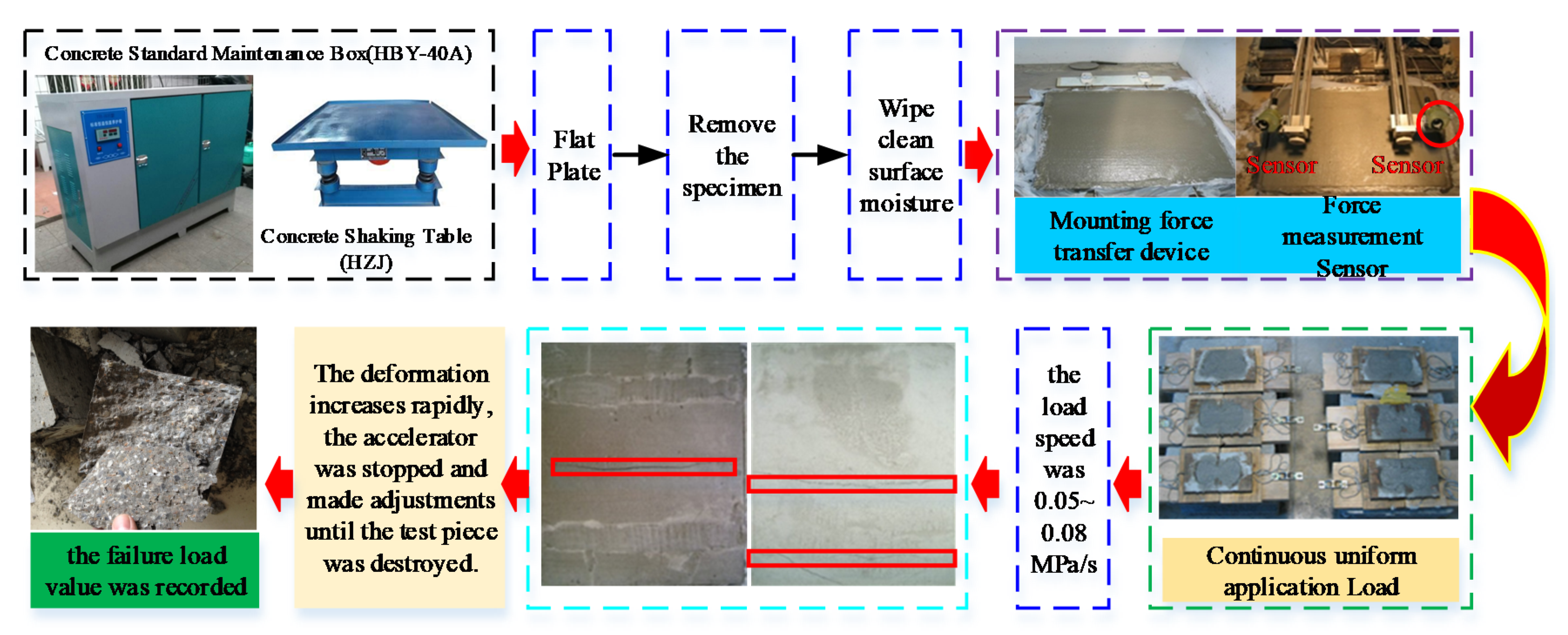
An HJW-60 concrete mixer, HZJ concrete shaking table, HBY-40A concrete standard curing box, and YJ-22 electric measuring instrument were used in the tensile test. Three test specimens were selected for each group, and the test results were accurate to 0.1 MPa [32,33]. The test scheme is shown in Figure 1.
- (1)
- After the concrete specimens were cured, the surface moisture of the specimens was wiped off and a force transfer device was placed on both sides of the specimens.
- (2)
- The specimen force sensor was attached and the corresponding stress sensors were placed on both sides. The stress monitor was attached on the left and right sides of the specimens.
- (3)
- The test piece was continuously and uniformly loaded, and the load speed was 0.05–0.08 MPa/s. When the deformation of the test piece increased rapidly, the accelerator was stopped and adjustments were made until the test piece was destroyed. At this time, the failure load value was recorded.
3. Test Results and Analysis of the AR-GFRC
3.1. Effect of Fiber Content on the Tensile Strength of Concrete
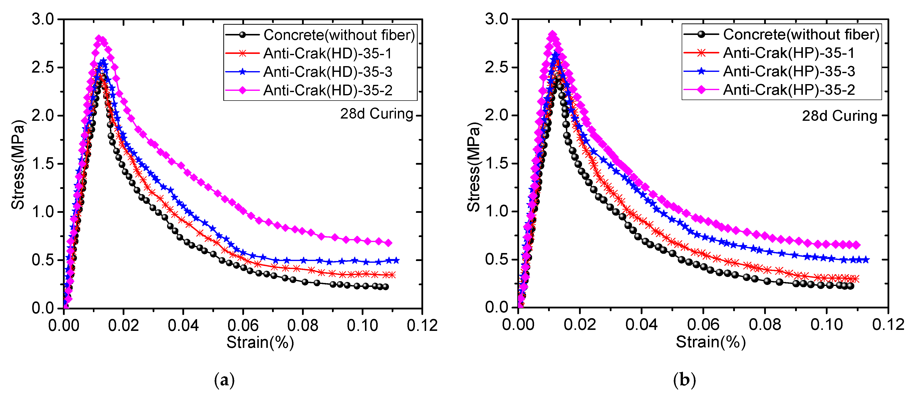
To investigate the effects of the fiber content on the tensile strength of the concrete, HD12 and HP12 AR-glass fiber were added to the concrete matrix. The strength grade was C35 and the volume content was 0%, 0.5%, 1%, and 1.5%. The tensile stress-strain curve of the AR-GFRC is shown in Figure 2.
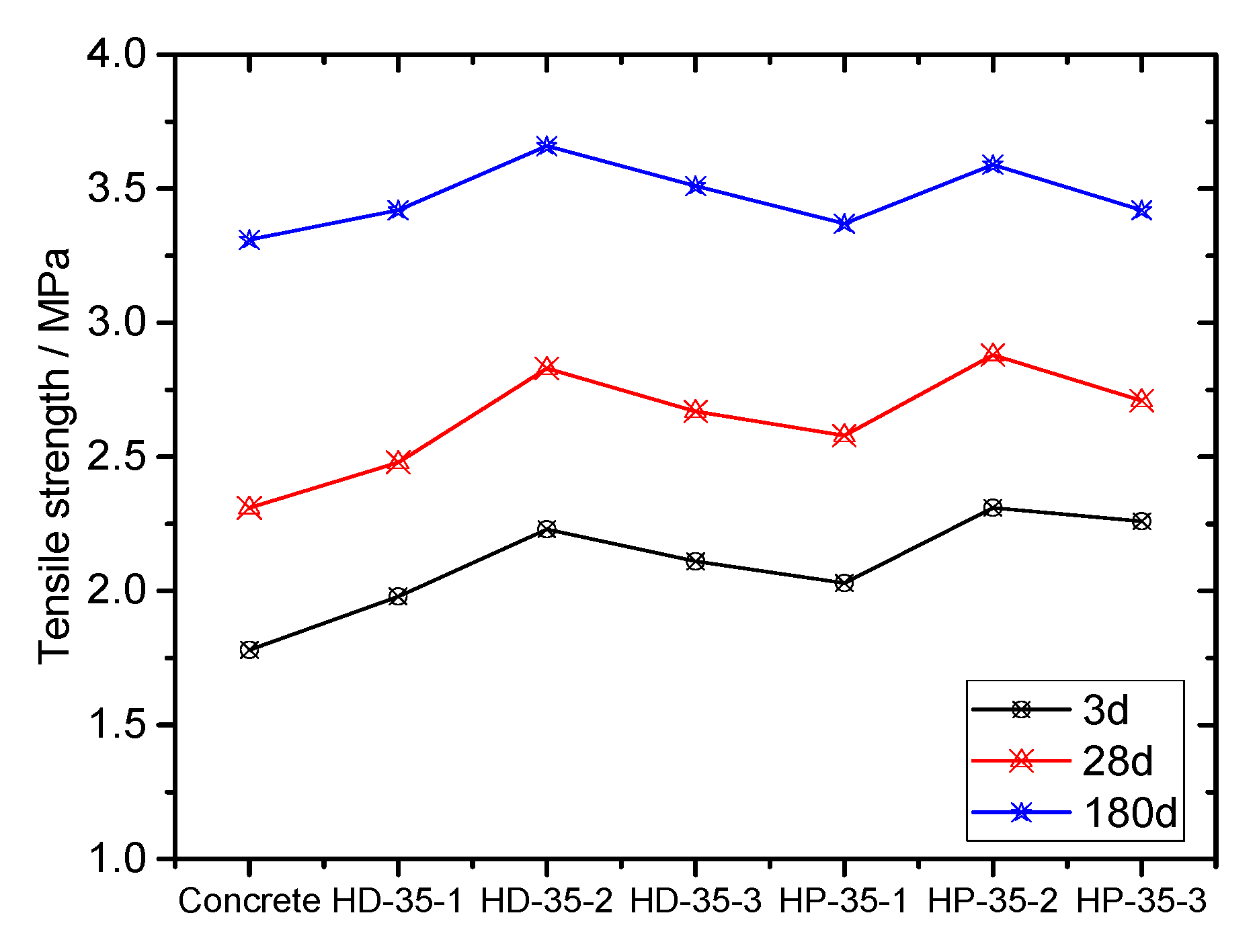
The tensile stress-strain curve represents a macroscopic reflection of the concrete’s tensile performance and parameters and characteristics of crack appearance, development, damage accumulation, penetration, and failure of the concrete under a tensile load. The addition of alkali-resistant glass fibers into concrete can significantly improve the tensile strength of concrete, as shown in Figure 2 and Figure 3. Compared with the concrete (without fiber), the three-day tensile strength of concrete with fiberglass increased by 11.2% to 29.7%, the strength of the 28-day tensile increased by 7.4% to 24.7%, and the 180-day tensile strength increased by 1.8% to 10.6%. Moreover, the tensile strength of concrete shows the law of increasing first and then decreasing with increasing alkali-resistant glass fiber doping. The peak strength and tensile strength first increased and then decreased with increasing fiber content at a fiber content of 1%. The AR-GFRC specimens had higher peak strength and residual strength after cracking than the concrete (without fiber).
Fiber has obvious cracking effects in concrete. The main reason is that there are micro-cracks of different sizes inside the concrete, and the impact of micro-cracks against pull strength is much greater than the pressure strength. When mixed with alkali-resistant glass fibers, fibers prevent the production of these cracks, thereby reducing the number of cracks, and making the size of the cracks smaller, which reduces the stress strength factor of the tip of the crack, eases the degree of stress concentration of the tip of the crack, and inhibits the initiation and expansion of the crack in the force process. When the amount of alkali-resistant glass fiber doping is too large, the dispersion of fiber in concrete is poor, thereby reducing the compactness of the concrete, and leading to decreases in cracking and folding strength.
3.2. Stress-Strain Curve of the Whole Process of the AR-GFRC
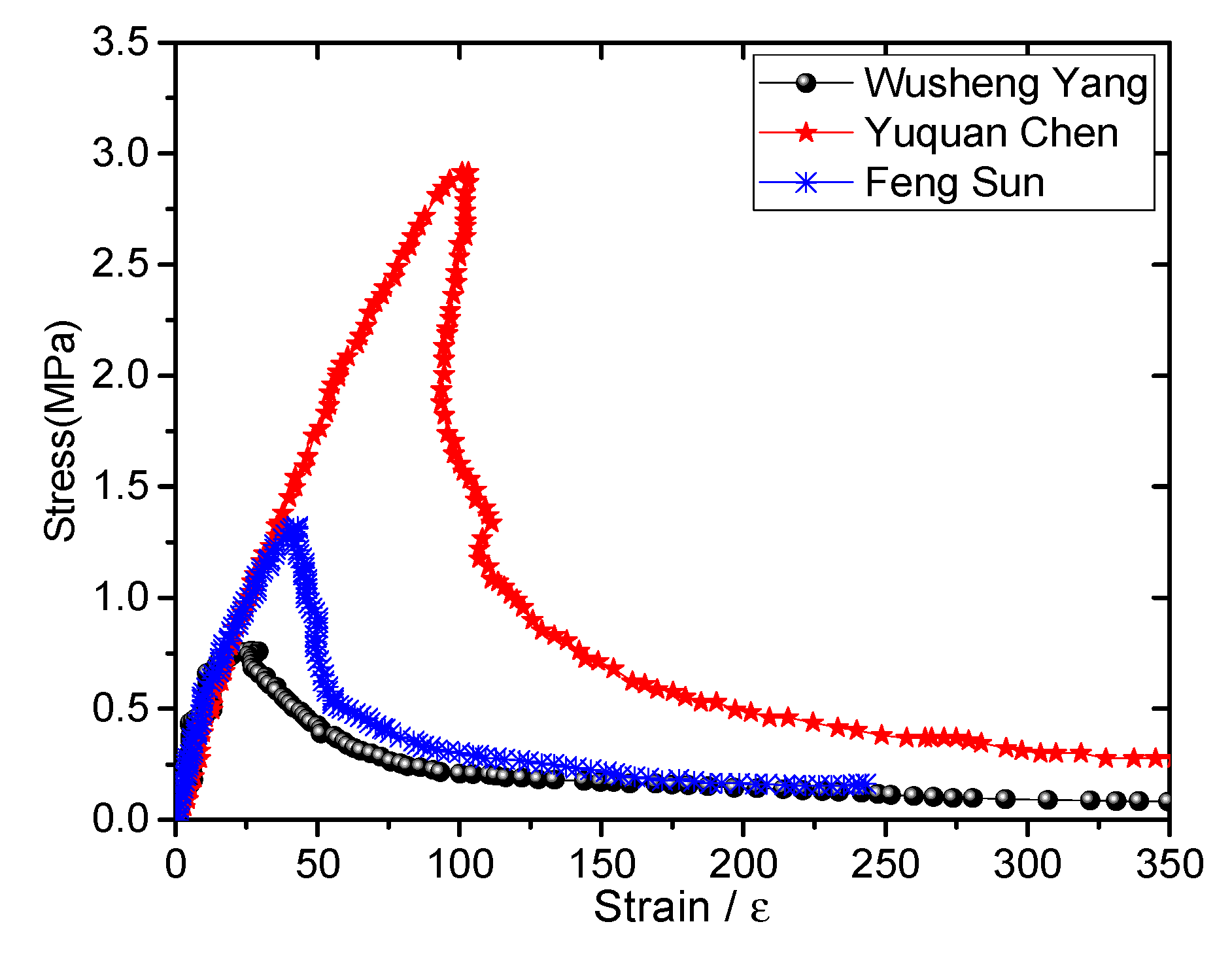
To study the curve change rule of the whole process of the AR-GFRC uniaxial tensile stress and strain, some typical concrete uniaxial tensile test data of several researchers [34,35,36] were selected for comparative studies. Yang [34] introduced a new test method for measuring the uniaxial tensile complete stress-strain curve, and obtained a uniaxial tensile stress-strain full curve of concrete. Chen [35] used independently developed test equipment to conduct an axial tension test on two groups of sample size 45 cm × 45 cm × 135 cm and obtained the test data by fitting an empirical formula of the complete curve of the full grade concrete. Sun [36] obtained the full stress-strain curve by using a uniaxial tension test and developed a mathematical model with clear physical significance and certain practicality through data fitting, as shown in Figure 4.
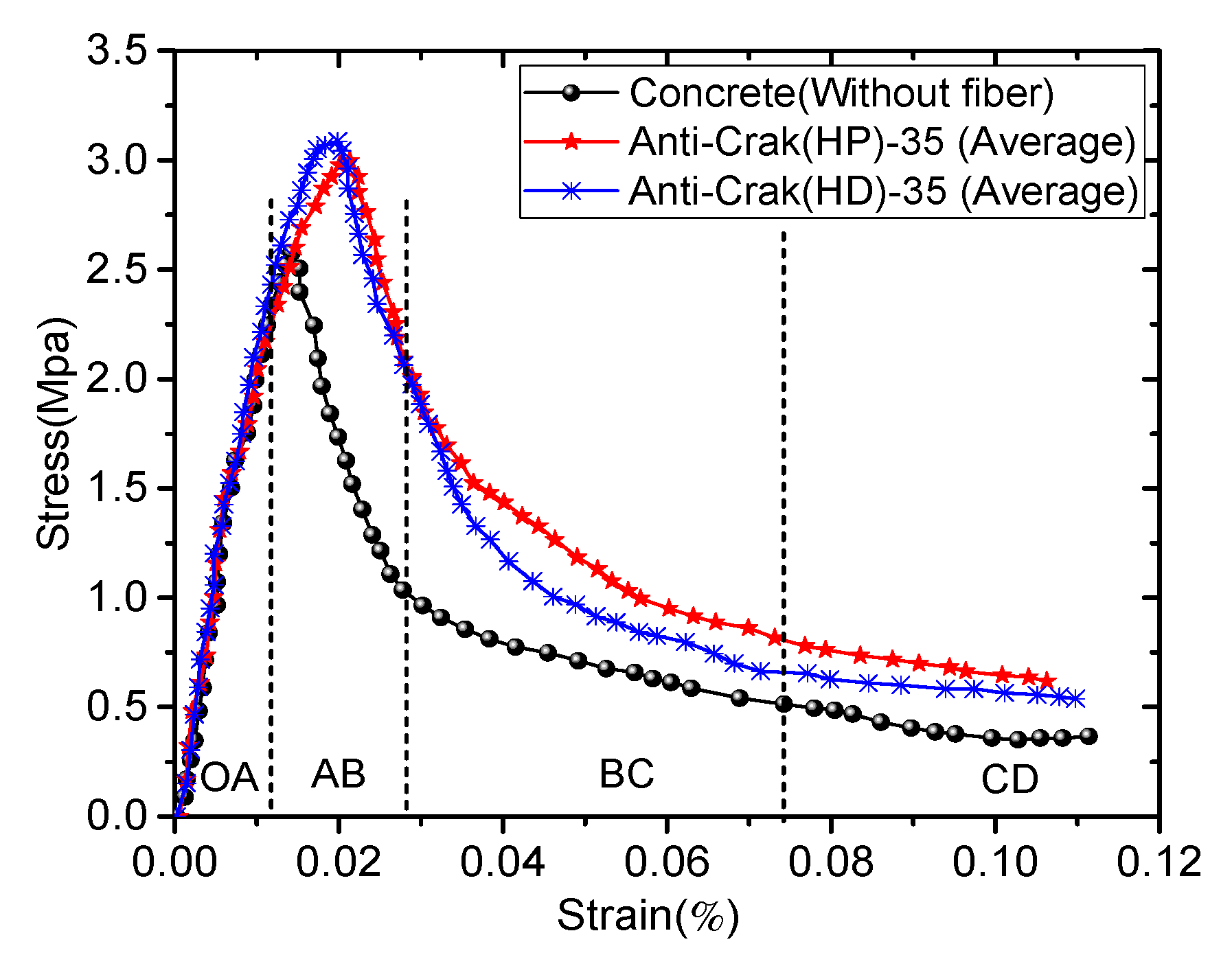
Based on the macroscopic failure morphology and tensile curve of the AR-GFRC obtained from the experiments, the stress-strain curve was redefined and divided. As shown in Figure 5, the uniaxial tensile stress-strain curves of the AR-GFRC can be divided into four parts, where the elastic deformation to micro-fracture development stage (OA region) showed the most effects.
We can draw some important conclusions:
- (1)
- Elastic deformation to micro-fracture development stage (OA region)
As shown in Figure 5, the σ-ε curve exhibits an approximately linear shape in this stage; the AB region is the elastic deformation stage and the σ-ε concrete curve increases. The BC region is the micro-crack development stage and the σ-ε curve is linear. The linear growth segment is 70–80% from the start of loading to the limit stress.
- (2)
- Stress peak stage (AB region)
As the load is continually applied, when the stress value exceeds 70–80% of the limit stress, the concrete has plastic deformation, the stress-deformation curve is slightly convex, and the slope decreases. When approaching the peak point of the stress, deformation increases and stress does not increase; the stress is quickly reduced, forming a basic symmetrical drop segment with the rising segment; the stress-deformation curve measured by a different ranging range is quite different; and the visible cracks of the test piece appear in the decreasing segment of the stress-deformation curve.
- (3)
- Progressive rupture stage (BC region)
The stress of the plain concrete and AR-GFRC rapidly increase, but the slope of the stress-strain curve of the plain concrete is smaller than that of the AR-GFRC, which indicates that the fiber content has an effect on crack development and propagation. Therefore, the crack development and expansion speed are slow. As more micro-cracks develop and the cracks finally penetrate the concrete, the compression state changes to an expansion state and the axial strain and volume strain rate rapidly increase. After reaching peak strength, the internal structure of the AR-GFRC is destroyed and the number of cracks increases; they become larger, are combined, and penetrate the concrete, eventually resulting in a macroscopic fracture surface. When the stress of the test piece drops to 45% to 50% of the maximum pull stress, the stress-deformation curve is at an inflection point, the deformation increases sharply, and the stress slowly decreases.
- (4)
- Post-rupture stage (CD region)
The stress rapidly decreases but the strain is still increasing, and the rate of increase is faster than during the previous stage. The deformation of the concrete specimens occurs due to block slips of the macroscopic fracture surface. At the fracture position, the alkali-resistant glass fiber is pulled out or off, and the bearing capacity of the specimen rapidly decreases, although some bearing capacity remains. The test piece still has a nominal stress of 15% to 20% (at this time, the macro-crack of the test piece has been fully developed and the effective pull area is greatly reduced), indicating that the deformation retracts after the release of the concrete stress on both sides of the crack, which is mainly the width of the concrete crack.
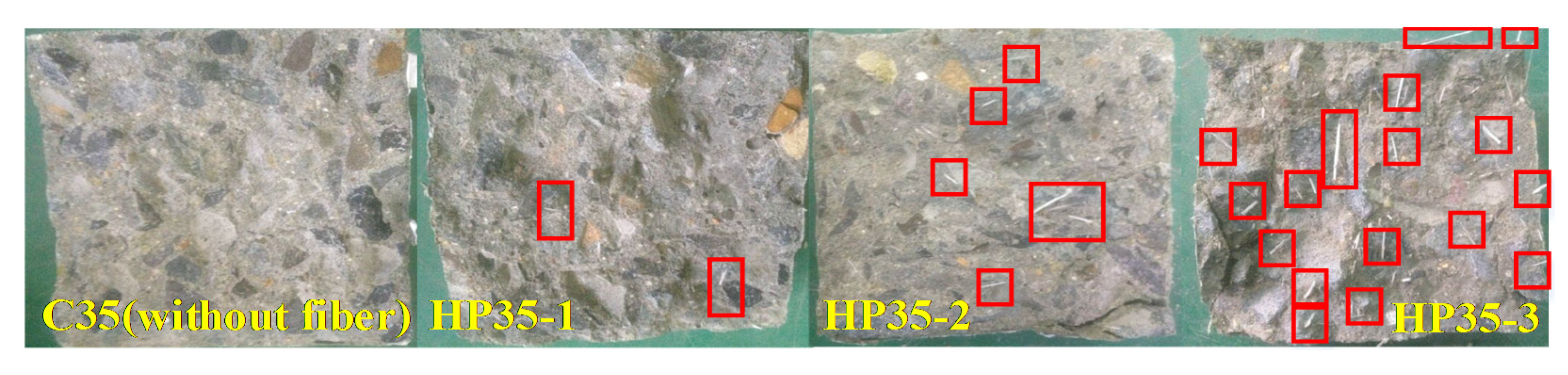
To analyze the uniaxial tensile results of AR-GFRC more intuitively, the shape of the samples after uniaxial tensile testing are shown in Figure 6. (An example is HP-35 concrete).
4. Development of the Statistical Damage Constitutive Model for the AR-GFRC
4.1. Assumptions
There are different micro-cracks, pores, and defects in the interior of quasi-brittle materials such as concrete and rock; stress concentration occurs under an external load. After the penetration stage of the cracks has been reached, some bearing capacity remains in the final failure stage of the concrete. The statistical meso-damage theory, micro-continuum theory, and composite material theory were used to define a new damage variable and to provide a more suitable statistical damage constitutive model of the AR-GFRC. The assumptions are as follows:
- (1)
- Assuming that the AR-GFRC consists of a series of isotropic elastic micro-units, each of which is an ideal elastomer with the same stiffness prior to the destruction.
- (2)
- Assuming that the micro-unit strength follows the Weibull distribution.
- (3)
- Assuming that the concrete consists of an undamaged part and a damaged part and the stress-strain relationship of the undamaged part obeys Hooke’s law.
- (4)
- Assuming that the concrete damage only occurs under axial stress, damage occurs after a load has been applied, and immediately after damage, failure occurs.
4.2. Derivation of the Statistical Damage Constitutive Model
4.2.1. The Constitutive Equation of the Elastic Section of Uniaxial Tensile Concrete
The uniaxial tensile deformation process of AR-GFRC is divided into a nondestructive phase and damage evolution phase:
where is the elastic modulus of alkali resistant fiberglass concrete, which was deduced and verified in previous research by Zhang Cong et al. [32,33], and will not be repeated here.
4.2.2. The Constitutive Equation of the Inelastic Section in the Whole Process of Uniaxial Tensile Concrete
Based on the assumptions, the statistical damage constitutive model of the AR-GFRC, which considers the residual strength, is established.
The microelements of the AR-GFRC were analyzed. The macroscopic nominal axial stress is assumed to be and the stress of the undamaged part and damaged part of the concrete is and , respectively. The cross-sectional area of the element is and the cross-sectional areas of the elements in the undamaged and damaged parts are and , respectively, .
Based on assumption (1), we obtain:
is the axial damage variable or damage factor of the material where [37]. The damage variable correction coefficient is used to describe the residual strength after the peak strength [38]; it is defined as:
where is the residual strength after the peak strength and is the peak strength.
Equation (2) can be rewritten as:
The partial deformation of the undamaged part obeys Hooke’s law and is expressed as [39]:
Equation (4) is:
Based on the stress-strain characteristics of concrete and rock, it was concluded that the microscopic homogenous mechanical properties of quasi-brittle materials follow the Weibull distribution [40]. Therefore, it is assumed that the concrete damage variables also follow the Weibull distribution. The Weibull distribution of two parameters is defined as [41]:
where is the strain, represents the size parameters, and represents the shape parameters of the material.
By substituting Equation (7) into Equation (6), we obtain:
where is the strain at peak strength.
The geometric conditions of the stress-strain curve of quasi-brittle materials are as follows [42]: I. ; II. ; III. ; IV.
In Equation (8), to variable derivation can be obtained,
I and II. IV is put into Equation (9) to obtain:
When the peak strength is reached, can be determined by the limit method. That is , . It is:
According to Equation (11), we obtain:
By substituting Equation (12) into Equation (8), can be obtained based on III. ,
The residual strength of the AR-GFRC is usually determined using the peak strength model. The residual strength is calculated using the Mohr–Coulomb model:
where and are the residual internal friction angle and residual adhesion force of the material, and is a correction factor of the residual strength, which can be obtained by fitting the test data, = 22~25. The composite material theory was introduced by Hilles and Ziara [43,44]. The calculation model of the elastic modulus of the AR-GFRC is obtained by using the mechanical equilibrium equation:
where is the elastic modulus of the AR-GFRC, is the elastic modulus of the fiber, is the elastic modulus of the substrate, is the volume ratio of the fiber, and is the volume ratio of the substrate, .
However, the distribution of the fiber material in the concrete depends on the mixing conditions in practical applications and during the test [45]. The effects of the fiber content, fiber length, and interfacial bonding characteristics on the material strength were considered, and these effects are defined by the coefficients , , (), respectively. We assume that the coefficients are independent; is used to represent the effect between the three coefficients:
where is the coefficient of the th factor affecting the properties of the composite. Therefore, the elastic modulus of the randomly distributed fiber in the composite can be expressed as:
By integrating Equations (8), (12), (13) and (17), the statistical damage constitutive model of the AR-GFRC, which considers the residual strength, is obtained:
The modulus and strength of the AR-GFRC are proportional to the volume content of the fiber. is less than 1. However, the elastic modulus and strength of the alkali-resistant glass fiber are much greater than that of the concrete substrates, i.e., Ef > Em and σf > σm. Therefore, the tensile statistical damage constitutive model of AR-GFRC is:
4.3. Parameter Determination of the Statistical Damage Constitutive Model
The parameters in the model include: , , , , , , , , and . The mechanical parameters can be obtained from concrete tests [46,47,48]. can be obtained from Equation (14). The statistical parameters such as and are obtained from Equations (12), (13) and (17). Therefore, only the expression for the last parameter is given here.
5. Verification of the Statistical Damage Constitutive Model of the AR-GFRC
5.1. Verification of Field Test
5.1.1. Project Overview and Field Test
To apply the above research to actual projects, the tunnel portion of the Chenglan Railway Project of China Railway 14th Bureau was selected for field testing to verify the validity and applicability. The mileage of the selected tunnel is DK194 + 198~DK194 + 368, the tunnel width is 13.70 m, the center angle of the top arch is 120°, and the joints are developed. For the field test, typical test sections were selected with similar geological conditions, topography, and supporting conditions: test Section 1 (DK194 + 210~DK194 + 230), test Section 2 (DK194 + 270~DK194 + 290), and test Section 3 (DK194 + 325~DK194 + 345). Test Section 1 is a common concrete sprayed layer, and test Section 2 and Section 3 are alkali-resistant glass fiber sprayed layers with alkali-resistant glass fiber contents of 1.0% HP and 1.0% HD, respectively. The trends in stress of the concrete and the convergence value of the tunnel were obtained by field monitoring, which were used to qualitatively analyze and verify the validity of the above research.
5.1.2. On-Site Deformation Monitoring and Result Analysis
- (1)
- Stress variation in concrete lining
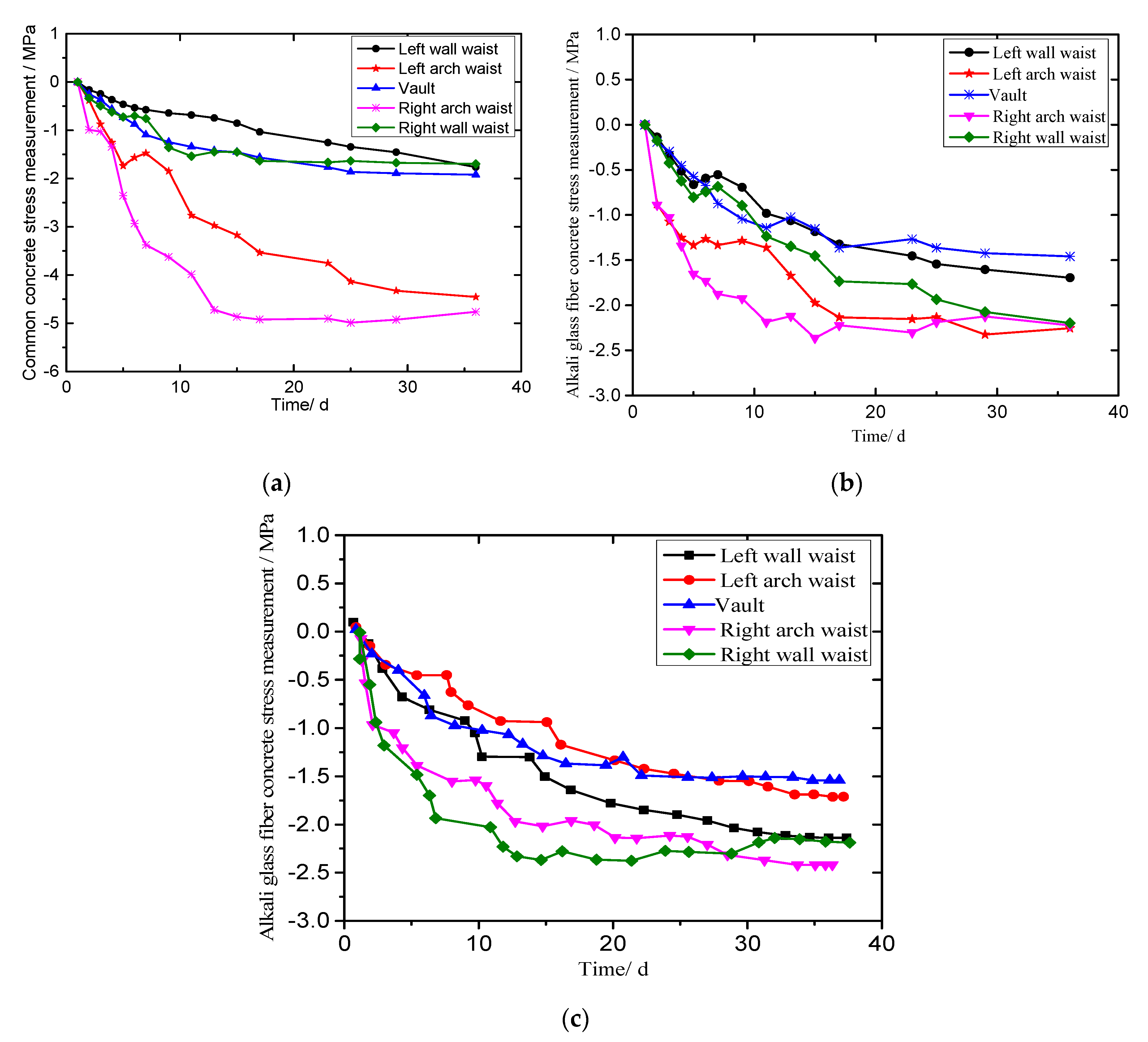
The monitoring plan was to monitor the key typical locations of the tunnel, such as the tunnel vault, left arch waist, left wall waist, right vault, and right arch waist lined with an ordinary spray layer and alkali-resistant glass fiber spray layer. The monitoring data are shown in Figure 7.
It can be seen from Figure 7 that the stress value of the shotcrete lining shows an increasing trend with time (the negative sign represents the direction). When it reaches 25 days, the stress of the two types of concrete spraying layers slowly increase and gradually stabilize. This is mainly because the stress of the surrounding rock tends to stabilize and reach equilibrium at this time. However, no matter the kind of concrete spray layer structure, the stress on the left and right wall waist of the tunnel is more obvious, and the stress distribution in the alkali-resistant glass fiber reinforced concrete spray layer is more uniform than that of the ordinary concrete spray layer, which is related to the pressure distribution of the surrounding rock being consistent. Therefore, it can be seen that the stress of the alkali-resistant glass fiber sprayed layer is much smaller than that of the ordinary concrete sprayed layer, and the stress distribution is more uniform.
- (2)
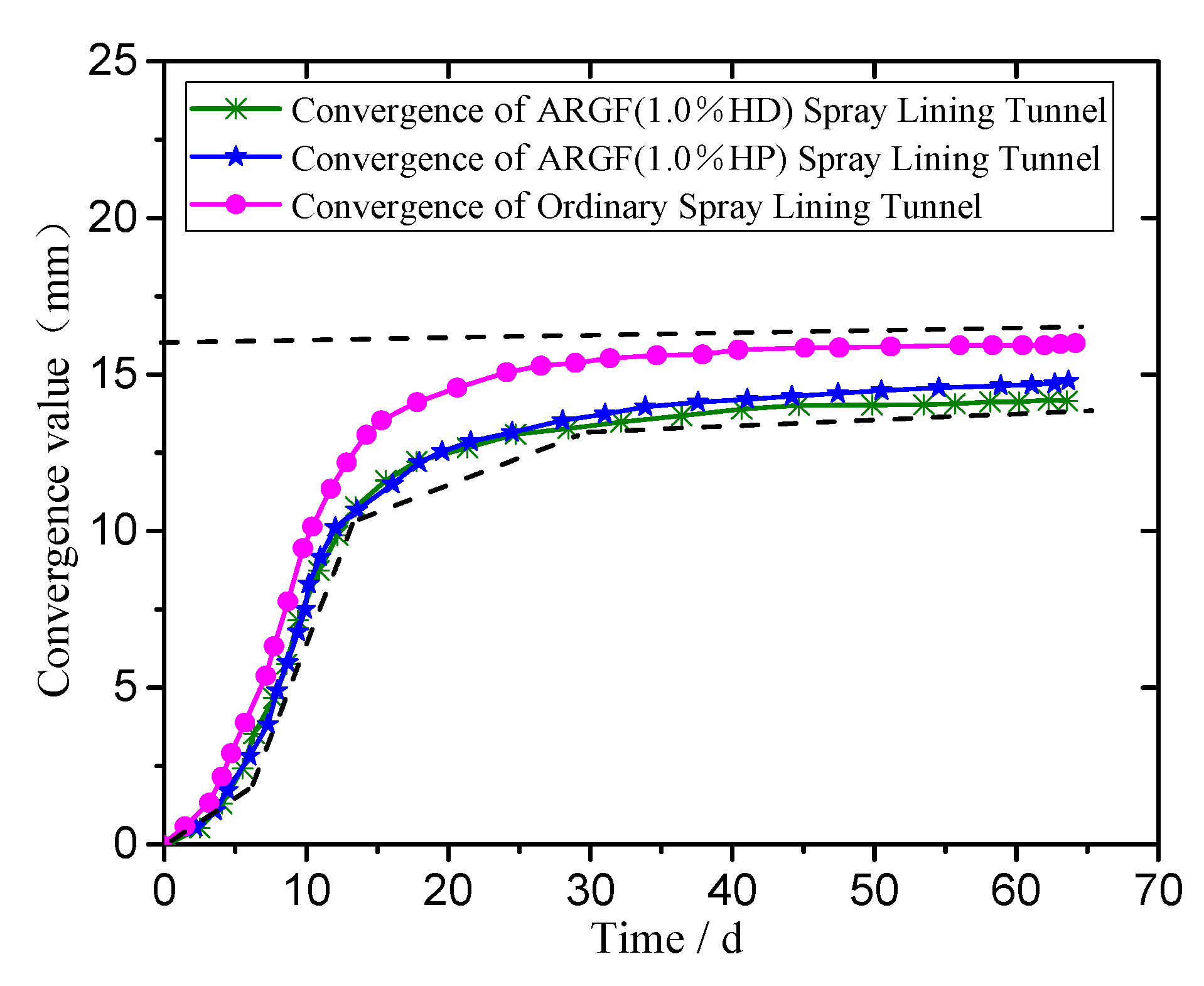
- Variation of the convergence value around the tunnel
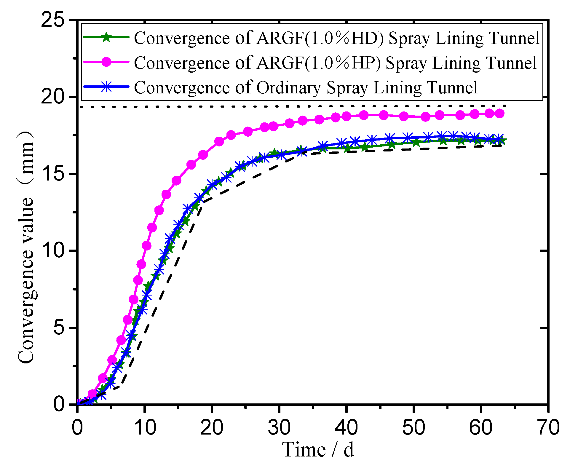
According to the monitoring and analysis of the displacement value of the tunnel under the ordinary spray layer and alkali-resistant glass fiber spray layer lining, the convergence of the position of the two arch waists and that of the vault are shown in Figure 8 and Figure 9.
As shown in Figure 8 and Figure 9, the convergence values of the two arch waists and arch of the ordinary spray layer and AR-GFRC spraying layer show rapid, exponential increases, and show a gradually stable trend. After stabilization, the convergence value gradually tends to balance and no longer changes. The convergence values of the two sills of the tunnel are greater than the convergence of the tunnel vault. Although the convergence value of the AR-GFRC sprayed layer is the same as that of the ordinary concrete sprayed layer, the convergence values of the tunnel arches and tunnel vaults are greater. This shows that the tensile strength of the concrete after adding alkali-resistant glass fiber increased, and the fiber plays a certain role in pulling and deforming the concrete, so that the stress distribution of the surrounding rock is uniform, and the stress concentration phenomenon does not easily occur.
5.2. Verification of the Theory and Laboratory Experiment
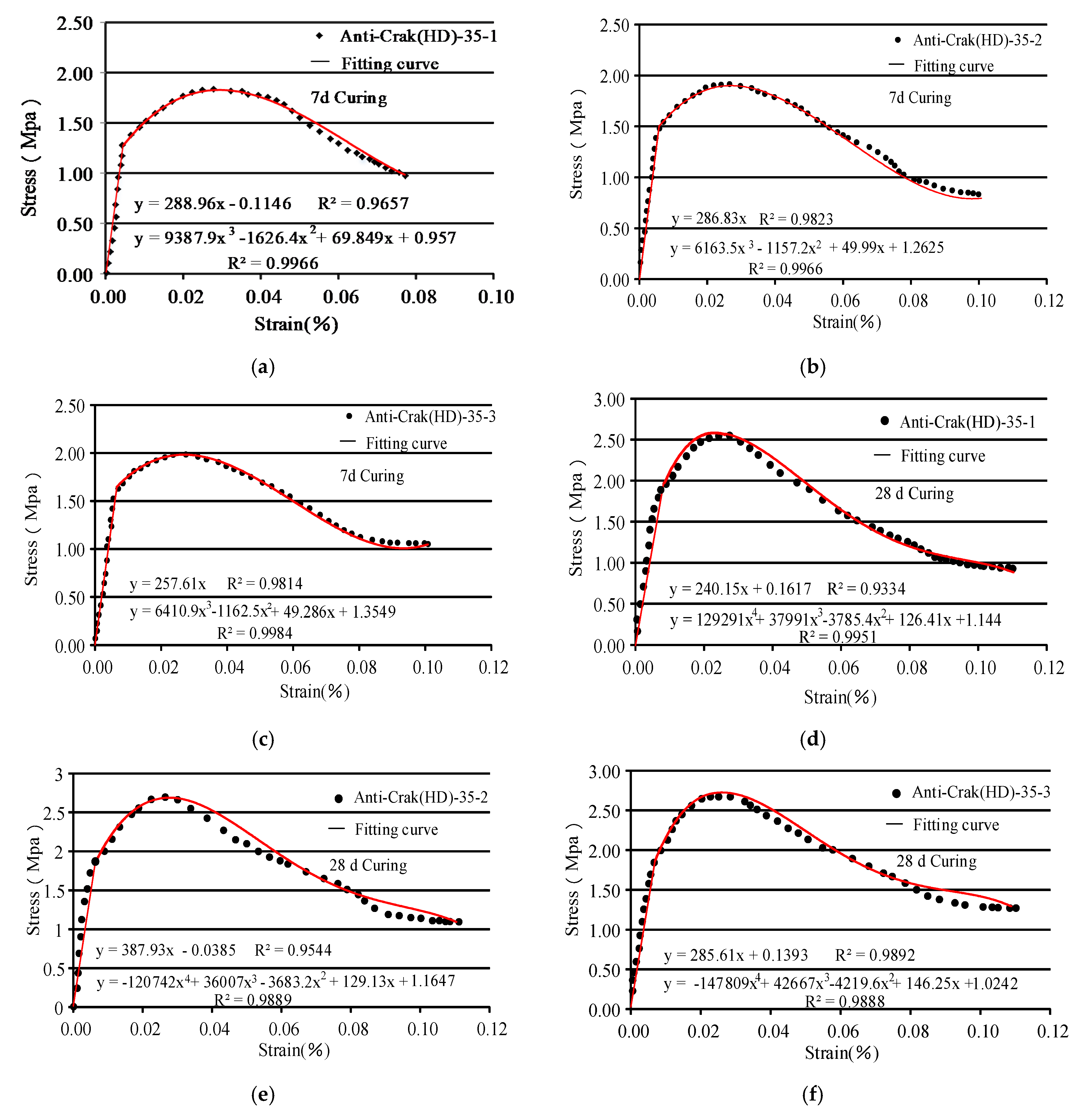
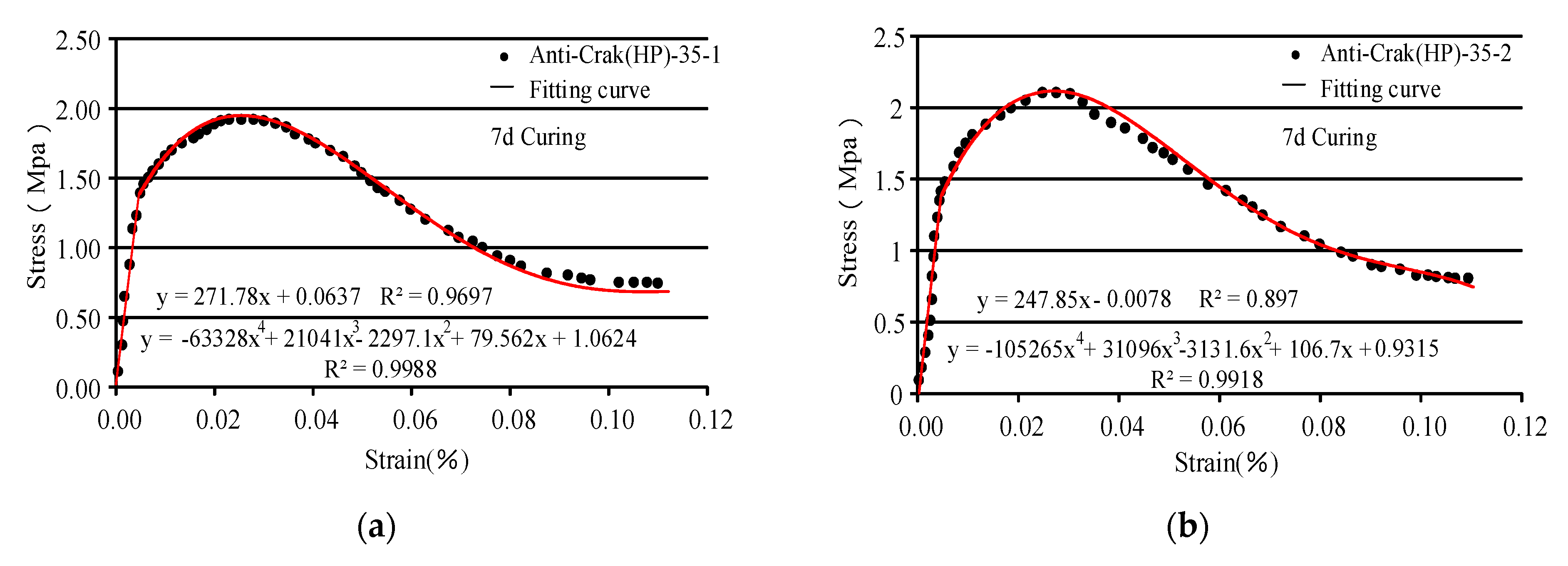
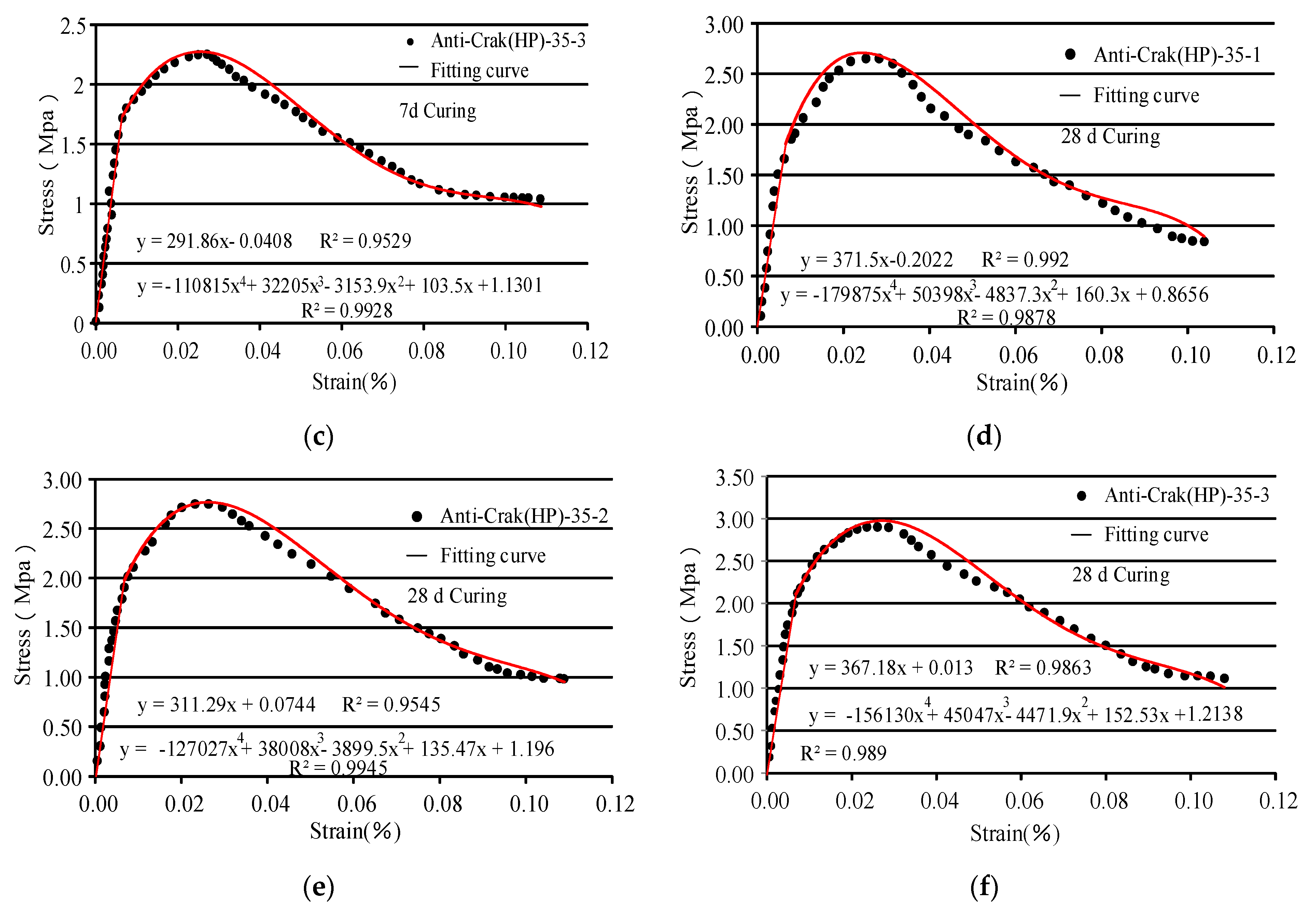
For the verification of the accuracy and applicability of the proposed model, we used data for HD concrete, HP concrete, and the experimental results for the concrete with different fiber contents (0.5%, 1%, and 1.5%) for 7 d and 28 d curing to obtain the material parameters and statistical damage parameters. The uniaxial tensile test curves were compared with the theoretical curves of the constitutive model, as shown in Figure 10 and Figure 11.
- (1)
- The proposed constitutive model describes the post-peak damage evolution of the AR-GFRC and the trends and characteristics of the concrete strength in the stress state. The theoretical and experimental stress-strain curves are in good agreement for the different fiber contents. The early tensile strength of the concrete was improved by the addition of alkali-resistant glass fiber.
- (2)
- As shown in Figure 10a–f and Figure 11a–f, the proposed tensile statistical damage constitutive model of AR-GFRC can accurately describe the stress-strain evolution law of the different fiber contents of alkali-resistant glass fiber concrete in this concrete tensile test. The content of the alkali-resistant glass fiber doping range was considered 0 to 1.5%, the 7-day peak strength difference between HD and HP concrete under standard curing between the experimental results and the theoretical results is small, and the 28-d peak strength shows similar patterns of change. The theoretical equation curve is consistent with the indoor test data curve in the elastic stage, peak strength, and nonlinear change segment after its peak. Different types of fibers (HD and HP) have little effect on the theoretical and test curves. This shows that the proposed AR-GFRC tensile statistical damage model is also applicable to the description of the concrete stress-strain curve of HD and HP fibers.
6. Discussion
AR-GFRC is used as an anchor spraying support material. The basic mechanical performance test assumes that the alkali-resistant glass fiber is in a continuous and uniform state. Alkali-resistant glass fibers may bond or break during mixing, and it is difficult for alkali-resistant glass fibers to be evenly distributed in concrete [32]. Based on this hypothesis, Cao [42] introduced the strain strength theory and hypothesis of particle strength of rock-like materials obeying Weibull random distribution to build a statistical damage constitutive model under triaxial compression. On this basis, a uniaxial tensile test of AR-GFRC was carried out to further explore the statistical damage relationship. The relationship can be used to truly reflect the actual pull state and crack conditions of concrete structure field engineering, which have been given in the verification section. It was used in the sprayed concrete layer of soft rock tunnel, and its effects were stronger than an ordinary concrete sprayed layer with great engineering application value.
The statistical damage constitutive model of the AR-GFRC, which considers residual strength, is based on the statistical meso-damage theory, microcontinuum theory, and composite material theory. It is assumed that the concrete consists of a series of isotropic elastic micro-units prior to failure and that the micro-unit strength follows a Weibull distribution; in addition, the interface between the alkali-resistant glass fiber and concrete matrix is not considered. However, if these two assumptions are not met, the calculation formula may not be applicable.
In the uniaxial tensile test, the lateral parts of the concrete were not damaged, and the part that was damaged due to axial stress after the axial failure was damaged due to residual stress. These observations are consistent with the results and stress-strain behavior of high strength concrete reinforced with glass fiber carried out by Muhammed [43].
The stress-strain curve that takes into consideration the residual strength effect is less affected by the interface discontinuity problem and is more representative of actual conditions. In practical engineering, the different parameters of the stress-strain curves of the AR-GFRC can be accurately described by the proposed constitutive model, and the parameters of this model have definitive physical meaning.
7. Conclusions
Uniaxial tensile tests were conducted for concrete with additions of alkali-resistant glass fiber with different fiber contents. The effects of fiber content on the concrete tensile strength were described macroscopically based on the types of failures of the concrete specimens.
- (1)
- A new damage variable of the AR-GFRC was defined based on the results of the uniaxial tensile test and the stress-strain curve was redefined by taking into consideration the residual strength.
- (2)
- The meso-statistical damage theory, microcontinuum theory, and composite material theory were used to develop a statistical damage constitutive equation of the AR-GFRC based on a Weibull distribution. The calculation methods for determining the mechanical and statistical parameters of the concrete have been provided, and the research results can be used to provide reference data for practical concrete engineering.
- (3)
- The constitutive theoretical curve was verified in MATLAB based on the uniaxial tensile test data of the concrete. The theoretical and experimental stress-strain curves of the AR-GFRC were in good agreement.
- (4)
- The fiber contents (0.5%, 1%, and 1.5%) and the size and shape parameters in the constitutive equation were quantified, and it was determined that the proposed model was well suited to describe the microscopic damage evolution and failure mechanism of the concrete while considering the residual strength effects. The results provide a theoretical basis and have practical application value.
Author Contributions
Conceptualization, X.S. and C.Z.; methodology, C.Z.; validation, X.S. and C.Z.; formal analysis, X.Z.; investigation, C.Z.; resources, C.Z.; data curation, X.S. and C.Z.; writing—original draft preparation, C.Z.; writing—review and editing, X.S. and C.Z.; visualization, X.S. and C.Z.; supervision, C.Z.; project administration, C.Z.; funding acquisition, X.S., C.Z. and X.Z. All authors have read and agreed to the published version of the manuscript.
Funding
This research was partially carried out with financial support from the China Scholarship Council (CSC) and supported by the Fundamental Research Funds for the Central Universities and Postgraduate Research and Practice Innovation Program of Jiangsu Province, grant number (2019B74214,SJKY19_04533), and project support from the National Natural Science Foundation of China, grant number (51579081).
Conflicts of Interest
The authors declare no conflict of interest.
References
- Fathi, H.; Lameie, T.; Maleki, M.; Yazdani, R. Simultaneous effects of fiber and glass on the mechanical properties of self-compacting concrete. Constr. Build. Mater. 2017, 133, 443–449. [Google Scholar] [CrossRef]
- Dimchev, M.; Caeti, R.; Gupta, N. Effect of carbon nanofibers on tensile and compressive characteristics of hollow particle filled composites. Mater. Des. 2010, 31, 1332–1337. [Google Scholar] [CrossRef]
- Takeda, K.; Nakashima, E. Nuclear Power and Environmental Concerns in the Aftermath of 3/11 Fukushima Daiichi Nuclear Power Plant Accident in Japan. In Globalization, Development and Security in Asia: Environment and Sustainable Development in Asia; World Scientific: Singapore, 2014. [Google Scholar]
- Keleştemur, O.; Arıcı, E.; Yıldız, S.; Gökçer, B. Performance evaluation of cement mortars containing marble dust and glass fiber exposed to high temperature by using Taguchi method. Constr. Build. Mater. 2014, 60, 17–24. [Google Scholar] [CrossRef] [Green Version]
- Tassew, S.T.; Lubell, A.S. Mechanical properties of glass fiber reinforced ceramic concrete. Constr. Build. Mater. 2014, 51, 215–224. [Google Scholar] [CrossRef]
- Kizilkanat, A.B.; Kabay, N.; Akyüncü, V.; Chowdhury, S.; Akça, A.H. Mechanical properties and fracture behavior of basalt and glass fiber reinforced concrete: An experimental study. Constr. Build. Mater. 2015, 100, 218–224. [Google Scholar] [CrossRef]
- Yuwaraj, M.G.; Santosh, B.D. Performance of Alkali-resistant Glass Fiber Reinforced Concrete. J. Reinf. Plast. Compos. 2006, 25, 617–630. [Google Scholar]
- Yildizel, S.A.; Ozturk, A.U. Micro Glass Fiber Reinforced Concrete. ICOCEE CESME 2018, 4, 24–27. [Google Scholar]
- Kwan, W.H.; Cheah, C.B.; Ramli, M.; Chang, K.Y. Alkali-resistant glass fiber reinforced high strength concrete in simulated aggressive environment. Materiales de Construcción 2018, 68, 1–14. [Google Scholar] [CrossRef]
- Chandramouli, K.; Rao, P.S.; Pannirselvam, N.; Sekhar, T.S.; Sravana, P. Chloride Penetration Resistance Studies on Concretes Modified with Alkali Resistant Glass Fibers. Am. J. Appl. Sci. 2010, 7, 371–375. [Google Scholar] [CrossRef]
- Yurdakul, A.; Dölekçekiç, E.; Karasu, B.; Günkaya, G. Characterization of Commercially Available Alkali Resistant Glass Fiber for Concrete Reinforcement and Chemical Durability Comparison with SrO-Mn2O3-Fe2O3-MgO-ZrO2-SiO2(SMFMZS SYSTEM GLASSES). Anadolu Univ. J. Sci. Technol. A Appl. Sci. Eng. 2012, 13, 95–102. [Google Scholar]
- Qin, X.; Li, X.; Cai, X. The applicability of alkaline-resistant glass fiber in cement mortar of road pavement: Corrosion mechanism and performance analysis. Int. J. Pavement Res. Technol. 2017, 10, 536–544. [Google Scholar] [CrossRef]
- Kumar, J.D.C.; Abhilash GV, S.; Khan, P.K.; Manikantasai, G.; Tarakaram, V. Experimental Studies on Glass Fiber Concrete. Am. J. Eng. Res. 2016, 5, 100–104. [Google Scholar]
- Yıldızel, S.A. Effects of Barite Sand Addition on Glass Fiber Reinforced Concrete Mechanical Behavior. Int. J. Eng. Appl. Sci. 2017, 9, 100–105. [Google Scholar] [CrossRef] [Green Version]
- Krishnan, K.A.; Anjana, R.; George, K.E. Effect of alkali-resistant glass fiber on polypropylene/polystyrene blends: Modeling and characterization. Polym. Compos. 2014, 37, 398–406. [Google Scholar] [CrossRef]
- Oh, H.S.; Moon, D.Y.; Kim, S.D. An Investigation on Durability of Mixture of Alkali-Resistant Glass and Epoxy for Civil Engineering Application. Procedia Eng. 2011, 14, 2223–2229. [Google Scholar] [CrossRef] [Green Version]
- Dougill, J.W. On stable progressively fracturing solids. Zeitschrift für Angewandte Mathematik und Physik ZAMP 1976, 27, 432–437. [Google Scholar] [CrossRef]
- Lemaitre, J. Coupled elasto-plasticity and damage constitutive equations. Comput. Methods Appl. Mech. Eng. Fr. 1985, 51, 31–49. [Google Scholar] [CrossRef]
- Kandarpa, S.; Krikner, D.J.; Spencer, B.F. Stochastic damage model for brittle materials subjected to monotonic loading. J. Eng. Mech. ASCE 1996, 122, 788–795. [Google Scholar] [CrossRef]
- Krajcinovic, D.; Silva, M.A.G. Statistical aspects of the continuous damage theory. Int. J. Solids Struct. 1982, 18, 551–562. [Google Scholar] [CrossRef]
- Krajcinovic, D. Constitutive equations for damaging materials. J. Appl. Mech. 1983, 50, 355–360. [Google Scholar] [CrossRef]
- Breysse, D. Probabilistic formulation of damage-evolution law of cementious composites. J. Eng. Mech. 1990, 1169, 1489–1511. [Google Scholar] [CrossRef]
- Guo, Y.; Kuang, Y. An elastoplastic micro-mechanical damage model for quasi-brittle materials under uniaxial loading. Int. J. Damage Mech. 2019, 28, 1191–1202. [Google Scholar] [CrossRef]
- Bakhshi, M.; Mobasher, B. Simulated shrinkage cracking in the presence of Alkali Resistant Glass fibers. Spec. Publ. 2011, 280, 1–14. [Google Scholar]
- Eiras, J.N.; Kundu, T.; Bonilla, M. Nondestructive Monitoring of Ageing of Alkali Resistant Glass Fiber Reinforced Cement (GRC). J. Nondestruct. Eval. 2013, 32, 300–314. [Google Scholar] [CrossRef]
- Lemaitre, J. How to use damage mechanics. Nucl. Eng. Des. 1984, 80, 233–245. [Google Scholar] [CrossRef]
- Wengui, C.; Sheng, Z.; Minghua, Z. Study on a statistical damage constitutive model with conversion between softening and hardening properties of rock. Eng. Mech. 2006, 23, 110–115. [Google Scholar]
- Weiya, X.; Lide, W. Study on statistical damage constitutive model of rock. Chin. J. Rock Mech. Eng. 2002, 21, 787–791. [Google Scholar]
- Mehta, P.K.; Aitcin, P.C. Microstructural basis of selection of materials and mix proportions for high-strength concrete. Spec. Publ. 1990, 121, 265–286. [Google Scholar]
- Alireza, A.; Mehdi, G.; Akram, F. Glass fber-reinforced epoxy composite with surface modifed graphene oxide: Enhancement of interlaminar fracture toughness and thermo-mechanical performance. Polym. Bull. 2018. [Google Scholar] [CrossRef]
- Abeysinghe, C.M.; Thambiratnam, D.P.; Perera, N.J. Flexural performance of an innovative hybrid composite floor plate system comprising glass–fibre reinforced cement, polyurethane and steel laminate. Compos. Struct. 2013, 95, 179–190. [Google Scholar] [CrossRef] [Green Version]
- Zhu, Z.; Zhang, C.; Meng, S.; Shi, Z.; Tao, S.; Zhu, D. A Statistical Damage Constitutive Model Based on the Weibull Distribution for Alkali-Resistant Glass Fiber Reinforced Concrete. Materials 2019, 12, 1908. [Google Scholar] [CrossRef] [PubMed] [Green Version]
- Zhang, C.; Zhu, Z.; Zhu, S.; He, Z.; Zhu, D.; Liu, J.; Meng, S. Nonlinear Creep Damage Constitutive Model of Concrete Based on Fractional Calculus Theory. Materials 2019, 12, 1505. [Google Scholar] [CrossRef] [PubMed] [Green Version]
- Yang, W.; Xue, M. Test method and equipment of stress-strain curves of concertein in direct tension. Ind. Constr. 2009, 39, 907–909. [Google Scholar]
- Chen, Y.; Du, C.; Zhou, W. Experimental study on the complete stress-deformation curve of full grade concrete under axial tension. J. Hydroelectr. Eng. 2010, 29, 76–81. [Google Scholar]
- Sun, F. Experimental Research for Complete Stress-Deformation Curve of Concrete in Uniaxial Tension. Master’s Thesis, Hohai University, Nanjing, China, 2007. [Google Scholar]
- Wu, N.; Zhang, C.; Maimaitiyusupu, S.; Zhu, Z. Investigation on Properties of Rock Joint in Compression Dynamic Test. KSCE J. Civ. Eng. 2019, 23, 3854–3863. [Google Scholar] [CrossRef]
- He, Z. The Research on Nonlinear Rheological Mechanics Models of Deep-Buried Tunnel Surrounding Rock and Its Application; HoHai University: Nanjing, China, 2018. [Google Scholar]
- Skrzypacz, P.; Nurakhmetov, D.; Wei, D. Generalized stiffness and effective mass coefficients for power-law Euler–Bernoulli beams. Acta Mech. Sin. 2020, 36, 160–175. [Google Scholar] [CrossRef]
- Eissa, F.H. Stress-Strength Reliability Model with the Exponentiated Weibull Distribution: Inferences and Applications. Int. J. Stat. Probab. 2018, 7. [Google Scholar] [CrossRef]
- Kasagani, H.; Rao, C.B.K. Effect of Short length Glass Fiber on dilated concrete in Compression and Tension. Proc. Inst. Civ. Eng. Struct. Build. 2018, 4, 1–12. [Google Scholar]
- Cao, R.L.; He, S.H.; Wei, J.; Wang, F. Study of modified statistical damage softening constitutive model for rock considering residual strength. Rock Soil Mech. 2013, 34, 1652–1661. [Google Scholar]
- Hilles, M.M.; Ziara, M.M. Mechanical behavior of high strength concrete reinforced with glass fiber. Eng. Sci. Technol. Int. J. 2019, 22, 920–928. [Google Scholar] [CrossRef]
- Khosravani, M.R.; Nasiri, S.; Anders, D.; Weinberg, K. Prediction of dynamic properties of ultra-high performance concrete by an artificial intelligence approach. Adv. Eng. Softw. 2019, 127, 51–58. [Google Scholar] [CrossRef]
- Brandon, F.; Pedram, S. Contribution of Longitudinal GFRP Bars in Concrete Cylinders under Axial Compression. Can. J. Civ. Eng. 2018, 45, 458–468. [Google Scholar]
- Yu, W.; Xue, H.; Qian, M. Tensile and compressive properties of epoxy syntactic foams reinforced by short glass fiber. Indian J. Eng. Mater. Sci. 2017, 24, 283–289. [Google Scholar]
- Sun, W.; Zuo, Y.; Wang, S.; Wu, Z.; Liu, H.; Zheng, L.; Lou, Y. Pore structures of shale cores in different tectonic locations in the complex tectonic region: A case study of the Niutitang Formation in northern Guizhou, Southwest China. J. Nat. Gas Sci. Eng. 2020, 80, 103398. [Google Scholar] [CrossRef]
- Sun, W.; Zuo, Y.; Wu, Z.; Liu, H.; Zheng, L.; Wang, H.; Shui, Y.; Lou, Y.; Xi, S.; Li, T.; et al. Pore characteristics and evolution mechanism of shale in a complex tectonic area: Case study of the Lower Cambrian Niutitang Formation in Northern Guizhou, Southwest China. J. Pet. Sci. Eng. 2020, 193, 107373. [Google Scholar] [CrossRef]
Figure 1.
Test scheme.

Figure 2.
Tensile curves of alkali-resistant glass fiber reinforced concrete (AR-GFRC) and ordinary concrete. (a) HD 28 d curing and (b) HP 28 d curing.
Figure 2.
Tensile curves of alkali-resistant glass fiber reinforced concrete (AR-GFRC) and ordinary concrete. (a) HD 28 d curing and (b) HP 28 d curing.

Figure 3.
The law of the tensile strength of the specimen with time.

Figure 4.
Previous studies.

Figure 5.
The stress-strain curve of the deformation whole process of AR-GFRC.

Figure 6.
The shape of the samples after the uniaxial tensile.

Figure 7.
Variation of stress in concrete lining. (a) Common concrete spray; (b) AR-GFRC (1.0%HP); and (c) AR-GFRC (1.0%HD).
Figure 7.
Variation of stress in concrete lining. (a) Common concrete spray; (b) AR-GFRC (1.0%HP); and (c) AR-GFRC (1.0%HD).

Figure 8.
Convergence value of two arch waists of tunnels supported by different spray layers.

Figure 9.
Convergence value of arch vaults supported by different spray layers.

Figure 10.
The stress-strain curve of HD concrete under 7 d and 28 d of curing. (a) 0.5%, 7 d; (b) 1.0%, 7 d; (c) 1.5%, 7 d; (d) 0.5%, 28 d; (e) 1.0%, 28 d; and (f) 1.5%, 28 d.
Figure 10.
The stress-strain curve of HD concrete under 7 d and 28 d of curing. (a) 0.5%, 7 d; (b) 1.0%, 7 d; (c) 1.5%, 7 d; (d) 0.5%, 28 d; (e) 1.0%, 28 d; and (f) 1.5%, 28 d.

Figure 11.
The stress-strain curve of HP concrete under 7 d and 28 d of curing. (a) 0.5%, 7 d; (b) 1.0%, 7 d; (c) 1.5%, 7 d; (d) 0.5%, 28 d; (e) 1.0%, 28 d; and (f) 1.5%, 28 d.
Figure 11.
The stress-strain curve of HP concrete under 7 d and 28 d of curing. (a) 0.5%, 7 d; (b) 1.0%, 7 d; (c) 1.5%, 7 d; (d) 0.5%, 28 d; (e) 1.0%, 28 d; and (f) 1.5%, 28 d.


Table 1.
Basic performance parameters of different varieties of fibers.
| Type | Length/mm | Equivalent Diameter/um | Fracture Strength | Elongation at Break/% | Modulus/GPa | Melting Point/°C |
|---|---|---|---|---|---|---|
| Anti-Crak®HD | 6/12 | 14 | 1700 | 3.6 | 72 | 1580 |
| Anti-Crak®HP | 6/12 | 700 | 1700 | 3.6 | 72 | 1580 |
Table 2.
Gravel particle grading (%).
| Sieve Hole Size | 31.5 | 26.5 | 16.0 | 4.75 | 2.36 |
|---|---|---|---|---|---|
| Actual cumulative percentage of sieve remainder/% | 0 | 0~5 | 30~70 | 90~95 | 95~100 |
Table 3.
Mix ratio of concrete samples.
| Number | Name | Cement | Mineral Powder | Fly Ash | Sand | Stone | Water | Admixture | Fiber Contents (%) |
|---|---|---|---|---|---|---|---|---|---|
| C35 | Concrete (without fiber) | 245 | 100 | 95 | 735 | 1040 | 175 | 10.5 | 0 |
| HD-35-1 | Anti-Crak® (HD) Concrete | 245 | 100 | 95 | 735 | 1040 | 175 | 10.5 | 0.5 |
| HD-35-2 | 245 | 100 | 95 | 735 | 1040 | 175 | 10.5 | 1 | |
| HD-35-3 | 245 | 100 | 95 | 735 | 1040 | 175 | 10.5 | 1.5 | |
| HP-35-1 | Anti-Crak® (HP) Concrete | 245 | 100 | 95 | 735 | 1040 | 175 | 10.5 | 0.5 |
| HP-35-2 | 245 | 100 | 95 | 735 | 1040 | 175 | 10.5 | 1 | |
| HP-35-3 | 245 | 100 | 95 | 735 | 1040 | 175 | 10.5 | 1.5 |
© 2020 by the authors. Licensee MDPI, Basel, Switzerland. This article is an open access article distributed under the terms and conditions of the Creative Commons Attribution (CC BY) license (http://creativecommons.org/licenses/by/4.0/).
Share and Cite
MDPI and ACS Style
Shi, X.; Zhang, C.; Zhou, X. The Statistical Damage Constitutive Model of the Mechanical Properties of Alkali-Resistant Glass Fiber Reinforced Concrete. Symmetry 2020, 12, 1139. https://doi.org/10.3390/sym12071139
AMA Style
Shi X, Zhang C, Zhou X. The Statistical Damage Constitutive Model of the Mechanical Properties of Alkali-Resistant Glass Fiber Reinforced Concrete. Symmetry. 2020; 12(7):1139. https://doi.org/10.3390/sym12071139
Chicago/Turabian StyleShi, Xianzeng, Cong Zhang, and Xingde Zhou. 2020. "The Statistical Damage Constitutive Model of the Mechanical Properties of Alkali-Resistant Glass Fiber Reinforced Concrete" Symmetry 12, no. 7: 1139. https://doi.org/10.3390/sym12071139
Note that from the first issue of 2016, this journal uses article numbers instead of page numbers. See further details here.