Heat Transfer Improvement in a Double Backward-Facing Expanding Channel Using Different Working Fluids
by
 , and
, and
Tuqa Abdulrazzaq
1, 
Hussein Togun
2 ,
,
Hamed Alsulami
3,
Marjan Goodarzi
4 and
Mohammad Reza Safaei
5,6,3,* 1
Petroleum & Gas Engineering Department, University of Thi-Qar, Nassiriya 64001, Iraq
2
Biomedical Engineering Department, University of Thi-Qar, Nassiriya 64001, Iraq
3
NAAM Research Group, Department of Mathematics, Faculty of Science, King Abdulaziz University, Jeddah P.O.Box 80259, Saudi Arabia
4
Sustainable Management of Natural Resources and Environment Research Group, Faculty of Environment and Labour Safety, Ton Duc Thang University, Ho Chi Minh City 700000, Vietnam
5
Institute of Research and Development, Duy Tan University, Da Nang 550000, Vietnam
6
Faculty of Electrical-Electronic Engineering, Duy Tan University, Da Nang 550000, Vietnam
*
Author to whom correspondence should be addressed.
Symmetry 2020, 12(7), 1088; https://doi.org/10.3390/sym12071088
Submission received: 26 May 2020
/
Revised: 18 June 2020
/
Accepted: 21 June 2020
/
Published: 1 July 2020
(This article belongs to the Special Issue Turbulence and Multiphase Flows and Symmetry)
Abstract
:This paper reports a numerical study on heat transfer improvement in a double backward-facing expanding channel using different convectional fluids. A finite volume method with the k-ε standard model is used to investigate the effects of step, Reynolds number and type of liquid on heat transfer enhancement. Three types of conventional fluids (water, ammonia liquid and ethylene glycol) with Reynolds numbers varying from 98.5 to 512 and three cases for different step heights at a constant heat flux (q = 2000 W/m2) are examined. The top wall of the passage and the bottom wall of the upstream section are adiabatic, while the walls of both the first and second steps downstream are heated. The results show that the local Nusselt number rises with the augmentation of the Reynolds number, and the critical effects are seen in the entrance area of the first and second steps. The maximum average Nusselt number, which represents the thermal performance, can be seen clearly in case 1 for EG in comparison to water and ammonia. Due to the expanding of the passage, separation flow is generated, which causes a rapid increment in the local skin friction coefficient, especially at the first and second steps of the downstream section for water, ammonia liquid and EG. The maximum skin friction coefficient is detected in case 1 for water with Re = 512. Trends of velocities for positions (X/H1 = 2.01, X/H2 = 2.51) at the first and second steps for all the studied cases with different types of convectional fluids are indicated in this paper. The presented findings also include the contour of velocity, which shows the recirculation zones at the first and second steps to demonstrate the improvement in the thermal performance.
1. Introduction
In the last decades, heat transfer techniques have been adopted and investigated by many researchers around the world. One of the essential methods is the modification of geometry, such as ribbed channels, expanding or contracting channels and convergence and divergence channels. Separation and reattachment flow, which are frequently created by flow over forward-facing steps (FFSs) or backward-facing steps (BFSs), have been studied by many different researchers. A variety of applications of this research can be found in thermal systems in power plants, combustion furnaces, nuclear reactors, heat exchangers and electronic devices. A previous study of flow over a BFS was conducted by Abbot and Kline [1] and Goldstein et al. [2]. Experimental and numerical studies over a backward-facing step were performed by Armaly et al. [3]. The findings showed a decrease in the separation length for Reynolds numbers between 1200 and 5550 and a rise in the separation length for Reynolds numbers less than 1200. Aung [4] studied laminar fluid flow over a BFS experimentally and detected that the reduction in the Reynolds number led to the creation of small fluctuations. Abu-Nada [5] performed an investigation on fluid flow and heat transfer with different expansion ratios. It was found that the effect of both the Reynolds number and expansion ratio on entropy generation was undeniable. A review report on various positions (horizontal, vertical and inclined) for BFS-FFS channels with laminar flow was published by Abu-Mulaweh [6]. Masatoshi et al. [7] experimentally studied fluid flow through a BFS channel through suction over a slot at the end corner of a step. The outcomes showed an increase in the heat transfer coefficient at the separation zone and a decrease in pressure drop. In another investigation by Terhaar et al. [8], pulsating laminar heat transfer through a BFS channel was studied experimentally. They found a rise in the Nusselt number at specific Strouhal numbers.
Due to the recent improvement in computational fluid dynamics (CFD) programing, efforts to study velocity mechanisms and heat transfer features have been realized [9]. Abe at al. [10,11] adopted RANS with a new K-ε model for calculating the heat transfer and fluid flow in the recirculation and reattachment zones. Their findings are significantly compatible with the results of Vogel and Eaton [12]. Chiang and Tony [13], Tylli et al. [14] and Durst and Pereira [15] reported excellent agreement between the numerical and experimental data for fluid flow through a BFS at Re < 648. Biswas et al. [16] studied laminar fluid flow over a BFS with different step heights. An increase in separation length was observed with a rise in step height. This result is in accordance with the experimental data of Armaly et al. [3]. An investigation into the fluid flow and heat transfer over a DFFS (double forward-facing step) was performed numerically by Oztop et al. [17]. Their findings revealed that the heat transfer increment and the maximum thermal performance were reached at an aspect ratio of 1.
Over the last several years, many studies have focused on using nanofluids with separation flow in BFSs and FFSs, which have been considered by various researchers [18,19,20,21,22,23,24,25,26,27,28,29,30] with similar conclusions. Recently, the modeling of turbulent heat transfer over a microscale BFS was presented by Sadeq et al. [31]. They found that ethylene glycol had higher heat transfer augmentation in comparison to water. Tuqa et al. [32] have numerically studied turbulent TiO2-based nanofluid flow in an annular pipe with a sudden reduction. A rise in the surface heat transfer coefficient was found with growing nanoparticle volume fractions and Reynolds numbers. Laminar fluid flow over a BFS and FFS with three obstacles was studied by Shujit Kumar Bala et al. by implementing the lattice Boltzmann method (LBM) [33]. It was noticed that heat transfer could rise up to 80% with a Reynolds number increase of 100. Additionally, Yuan et al. [34] conducted a study on heat transfer for MWCNT (Multi-Walled Carbon Nanotube)-Fe3O4/water hybrid nanofluid flow over forward- and backward-facing step channels with a baffle fixed on its top wall. The results showed an increase in the average Nusselt number as the length of the baffle increased or as the baffle moved towards the backward-facing step. Fetta et al. [35] performed a numerical investigation into the influence of Bingham fluid flow over a backward-facing step to enhance the thermal performance. They found that increases in the Bingham number led to the reduction of recirculation zones, and increases in the Richardson number intensified recirculation zones. Large-eddy simulation (LES) and its comparison with direct numerical simulation (DNS) were reported in an investigation by Jure et al. [36]. LES data were in good agreement with the DNS data for predictions of temperature fluctuations.
Based on previous studies, the numerical investigation of laminar water, ammonia liquid and ethylene glycol flow through a DBFS (double backward-facing step) channel has not yet been studied. Therefore, this research can be considered the first. The current research aims to find the impacts of the step, Reynolds number and type of liquid on the thermal performance of the DBFS.
2. Numerical Approach
2.1. Physical Model
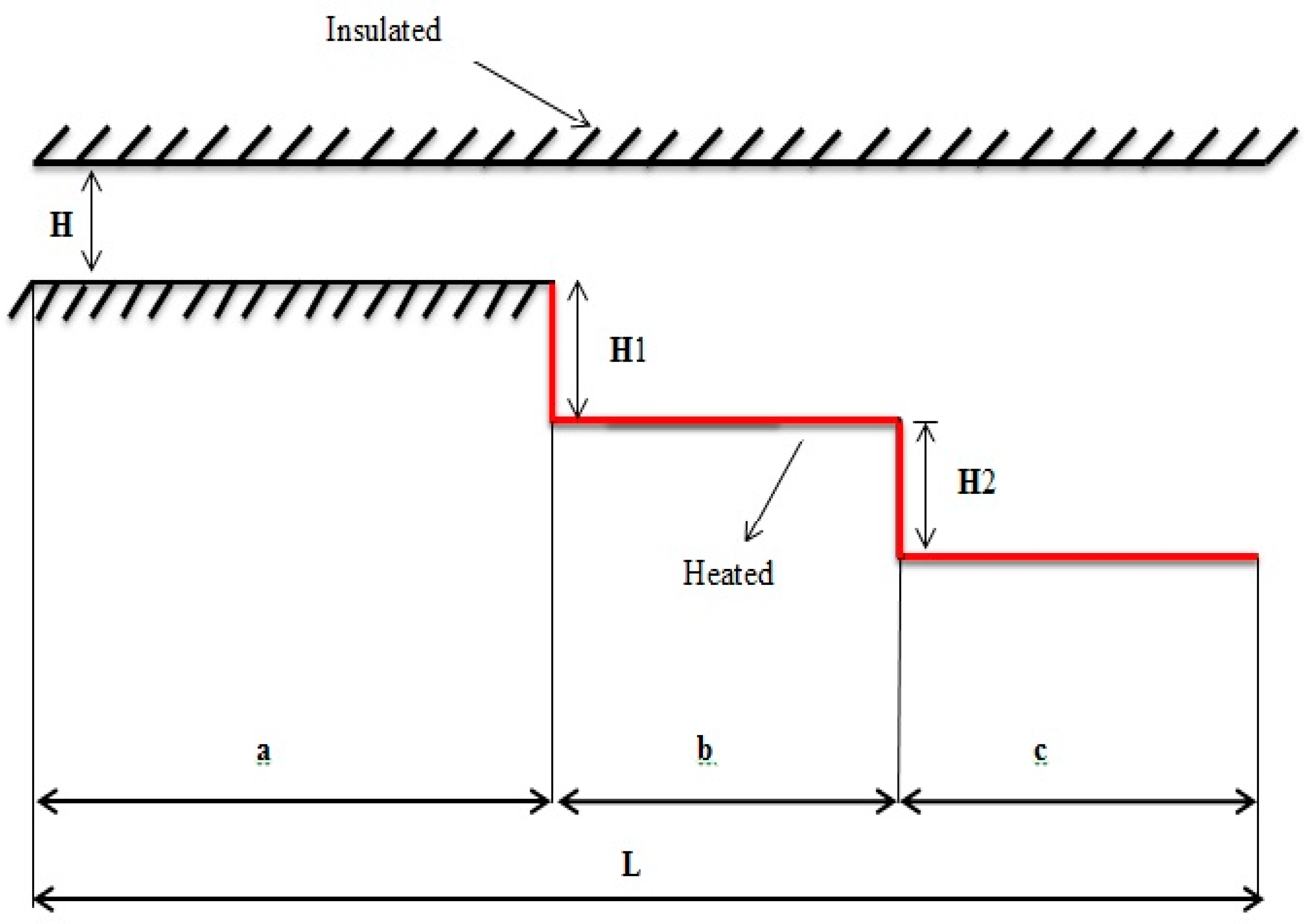
The two-dimensional DBFS of the expanding passage used in this study is presented in Figure 1. Three types of conventional fluids are considered as the base fluids, represented by water, ammonia liquid and ethylene glycol (EG). Three cases of dimensional geometry with different step heights are presented in Table 1. The upstream wall length (a) is 2000 mm, while the entry height (H) is 9.8 mm. The first (b) and second (c) downstream wall lengths are 500 mm with variable step heights. The top wall of the passage and the bottom of the upstream section are adiabatic, while the walls of both the first (b) and second (c) steps downstream are heated with a constant heat flux (q = 2000 W/m2). Four different velocities are used in this simulation, and the Reynolds numbers are 98.5, 190, 343 and 512.
2.2. Governing Equations
In the present model, the flow is assumed to be laminar, steady-state and incompressible. According to this hypothesis, Equations (1)–(4) are solved with the control volume method in this simulation.
The Reynolds number can be calculated by using Equation (5):
while the values of the Nusselt number and the skin friction coefficient are determined by the use of Equations (6) and (7), respectively:
where is the hydraulic diameter, H is the step height and is the wall shear stress.
The thermophysical properties of the convectional fluids (water, ammonia liquid and ethylene glycol) are presented in Table 2 for a constant temperature. The second-order upwind scheme is utilized for the discretization of equations. The convergence scales for the continuity, energy and momentum equations are selected as 10−6, 10−7 and 10−7, respectively.
3. Grid Independence Study and Data Validation
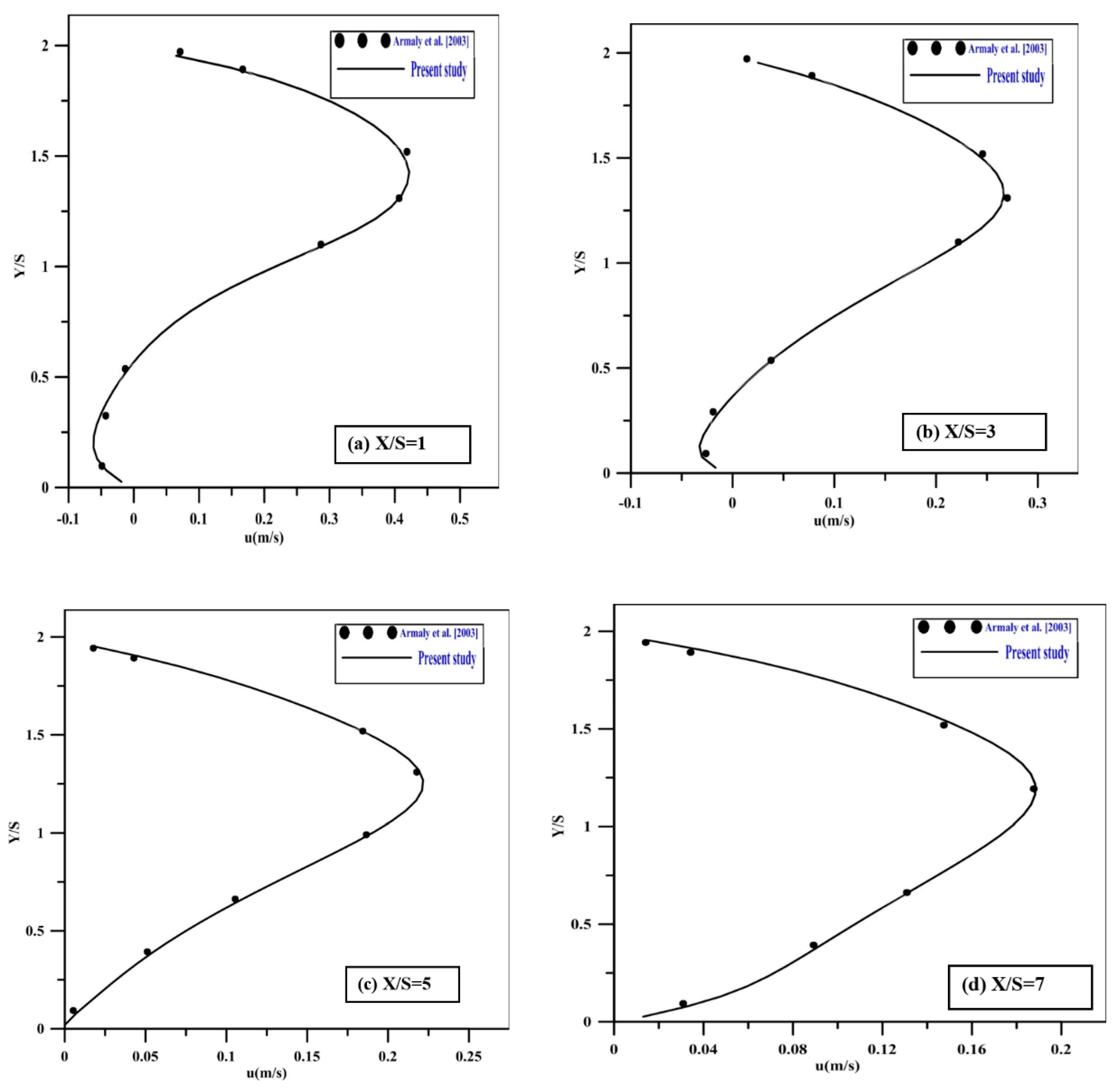
Computational fluid dynamics (CFD) based on ANSYS software was used to analyze the data obtained. It was used to create the configuration of the current model with the meshing process that was performed by ICEM and then exported to Fluent. The independent grid study was performed by boosting the number of elements [37,38]. The total grid numbers were varied between 94,681, 46,741 and 28,471. However, at the grid number of 28,471, the velocity variation was less than <4% in comparison to the finer grids. The validation of the model was performed by comparing the velocity profile in the expanding section of the passage at Re = 343 with those carried out by Armaly et al. [39] in similar circumstances, as presented in Figure 2a–d, where the data appear to be in excellent agreement.
4. Results and Discussion
The present simulations were conducted for three cases at various step heights, three types of conventional fluids (water, ammonia liquid and ethylene glycol), a constant and uniform heat flux value (q = 2000 W/m2) and four variations of the Reynolds number (98.5, 190, 343 and 512).
4.1. Nusselt Number
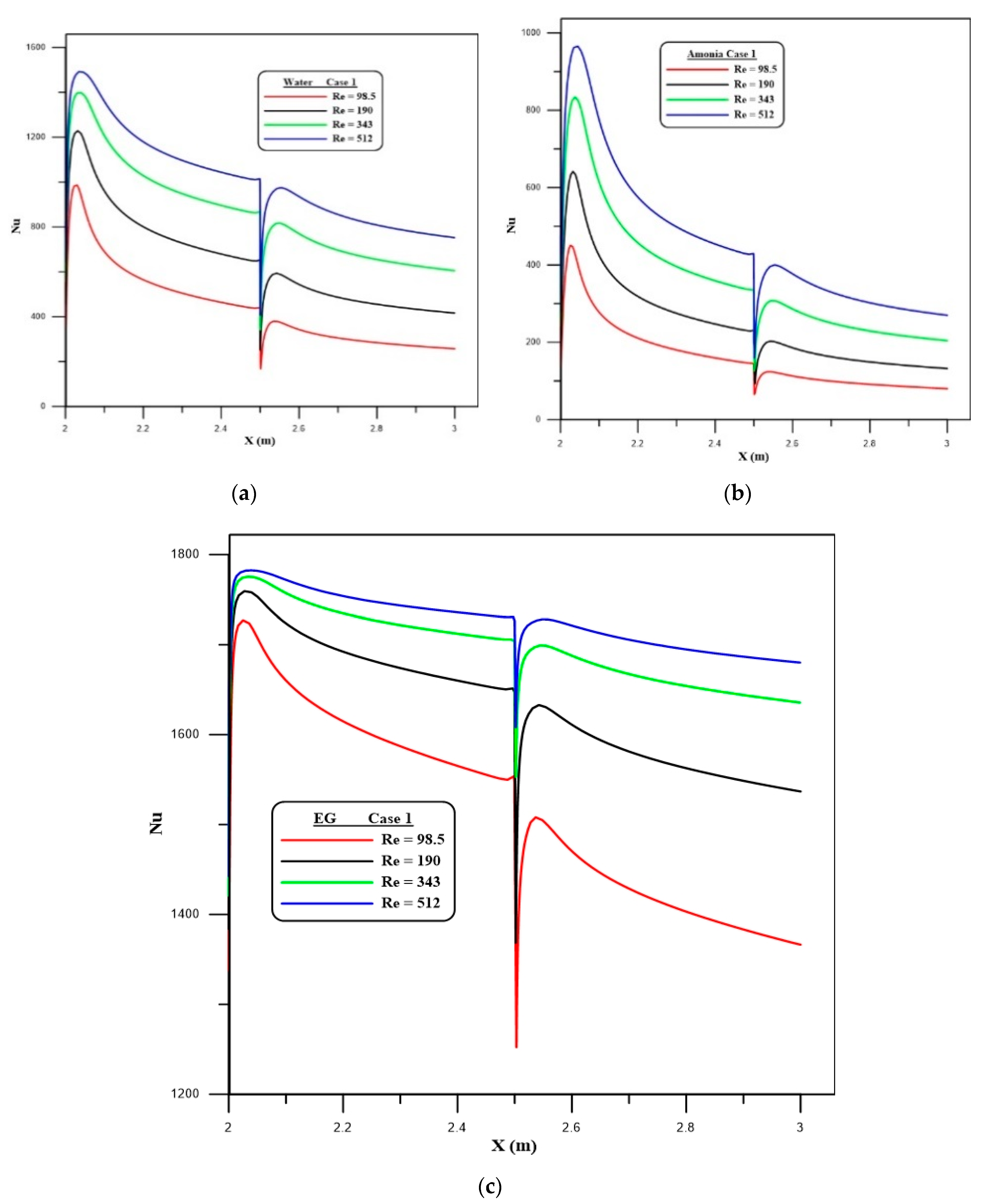
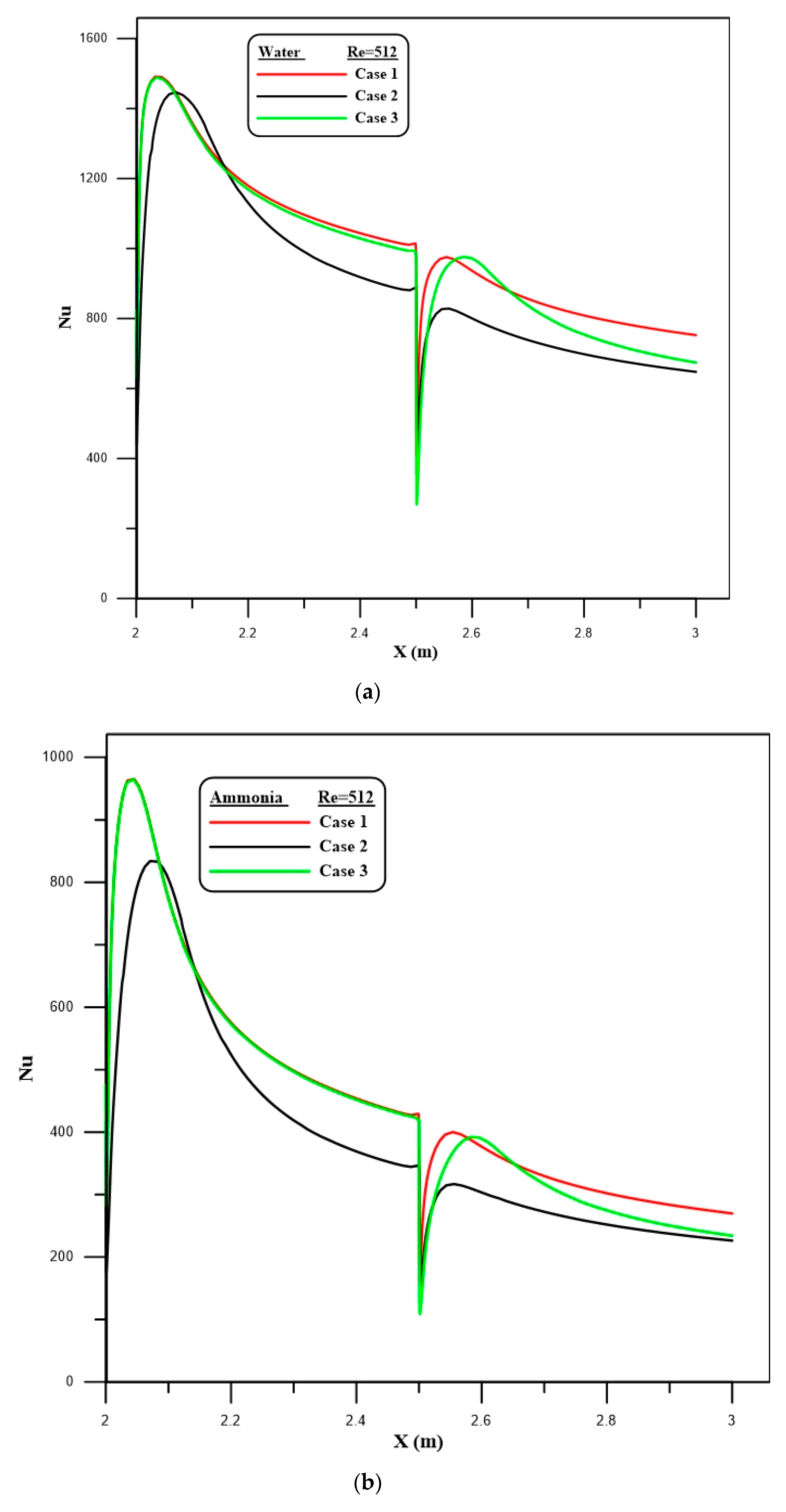
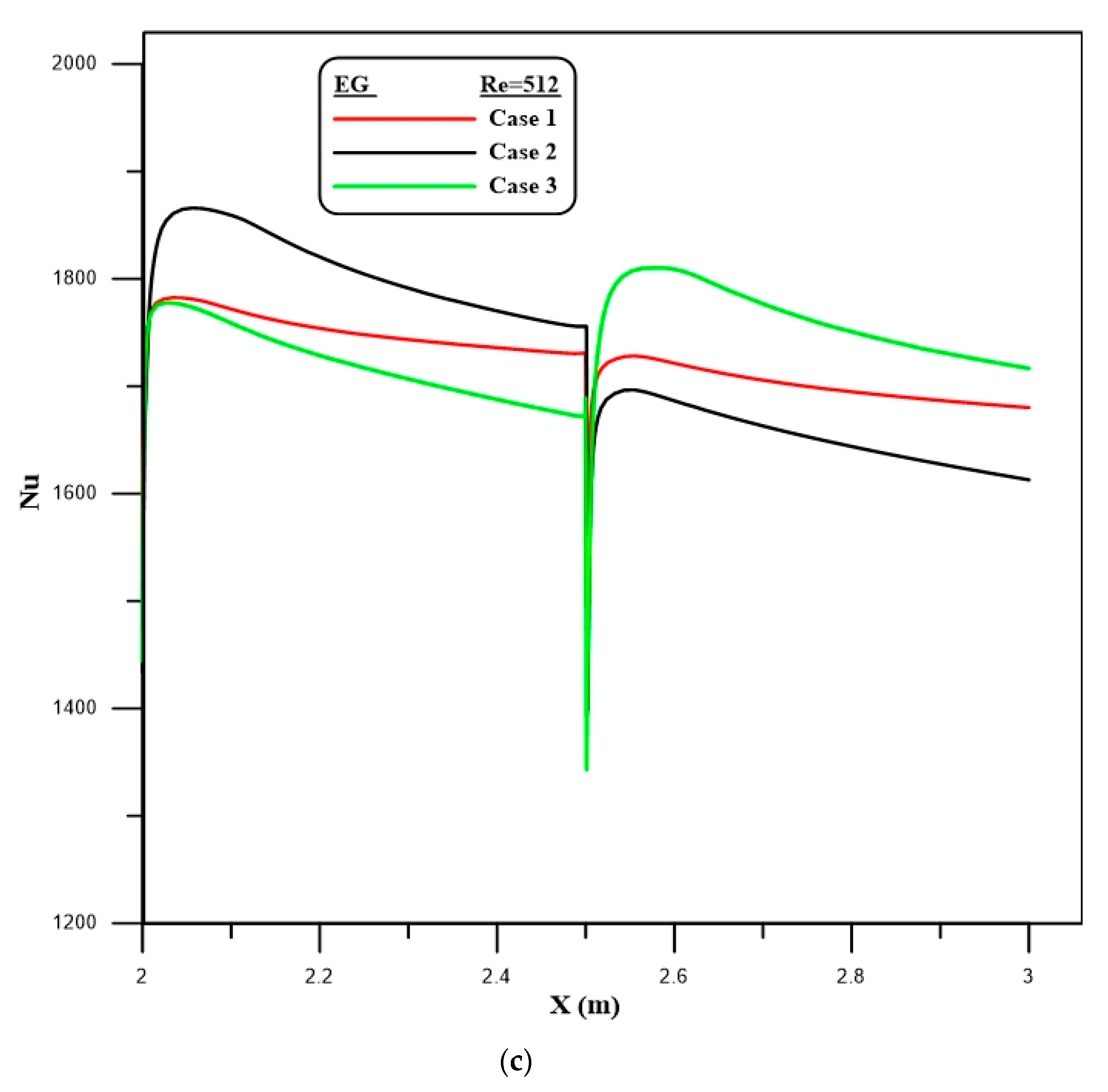
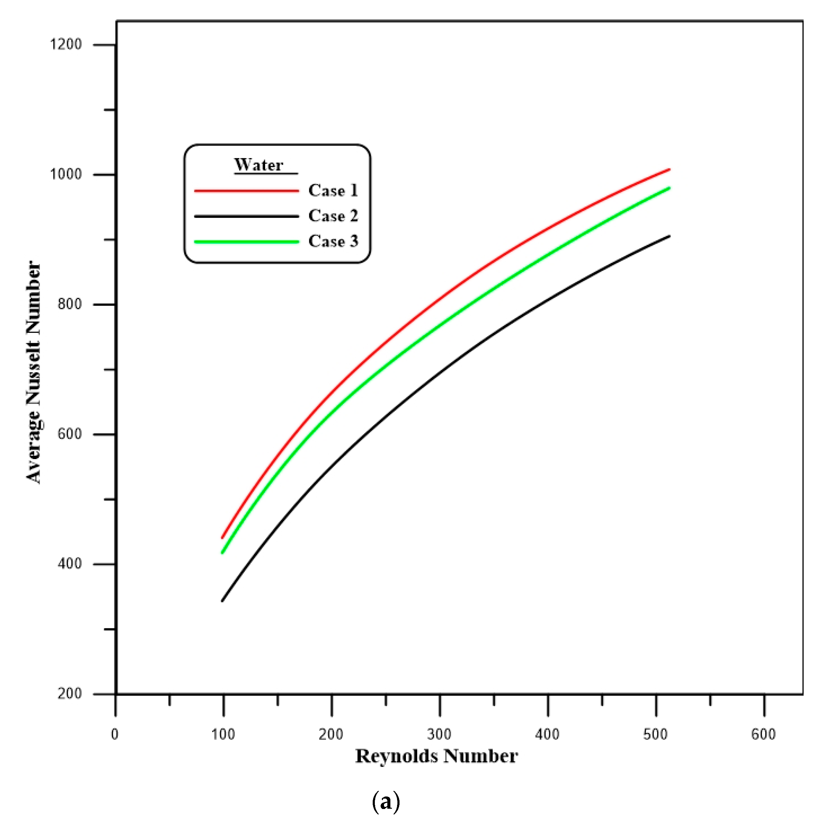
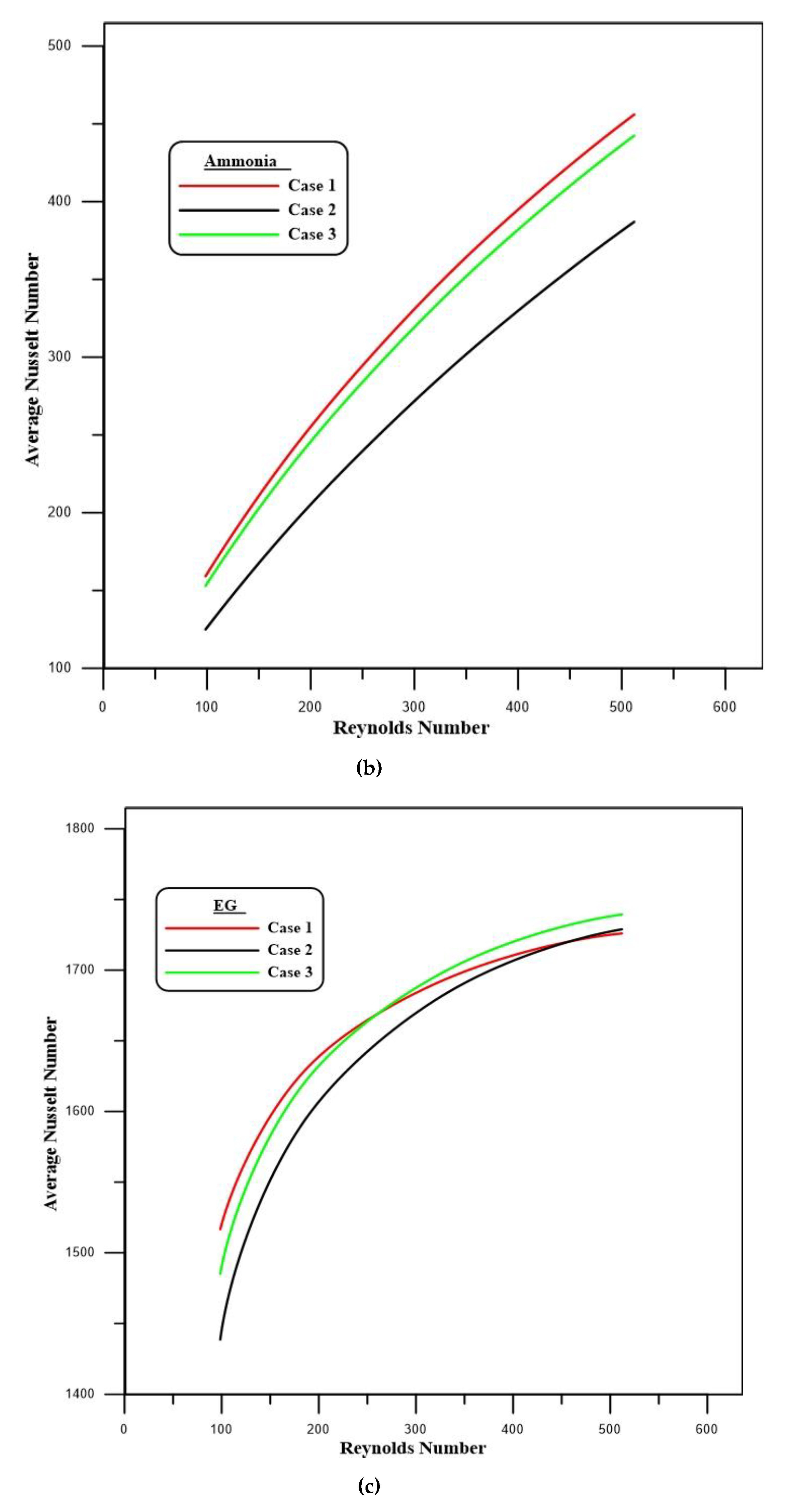
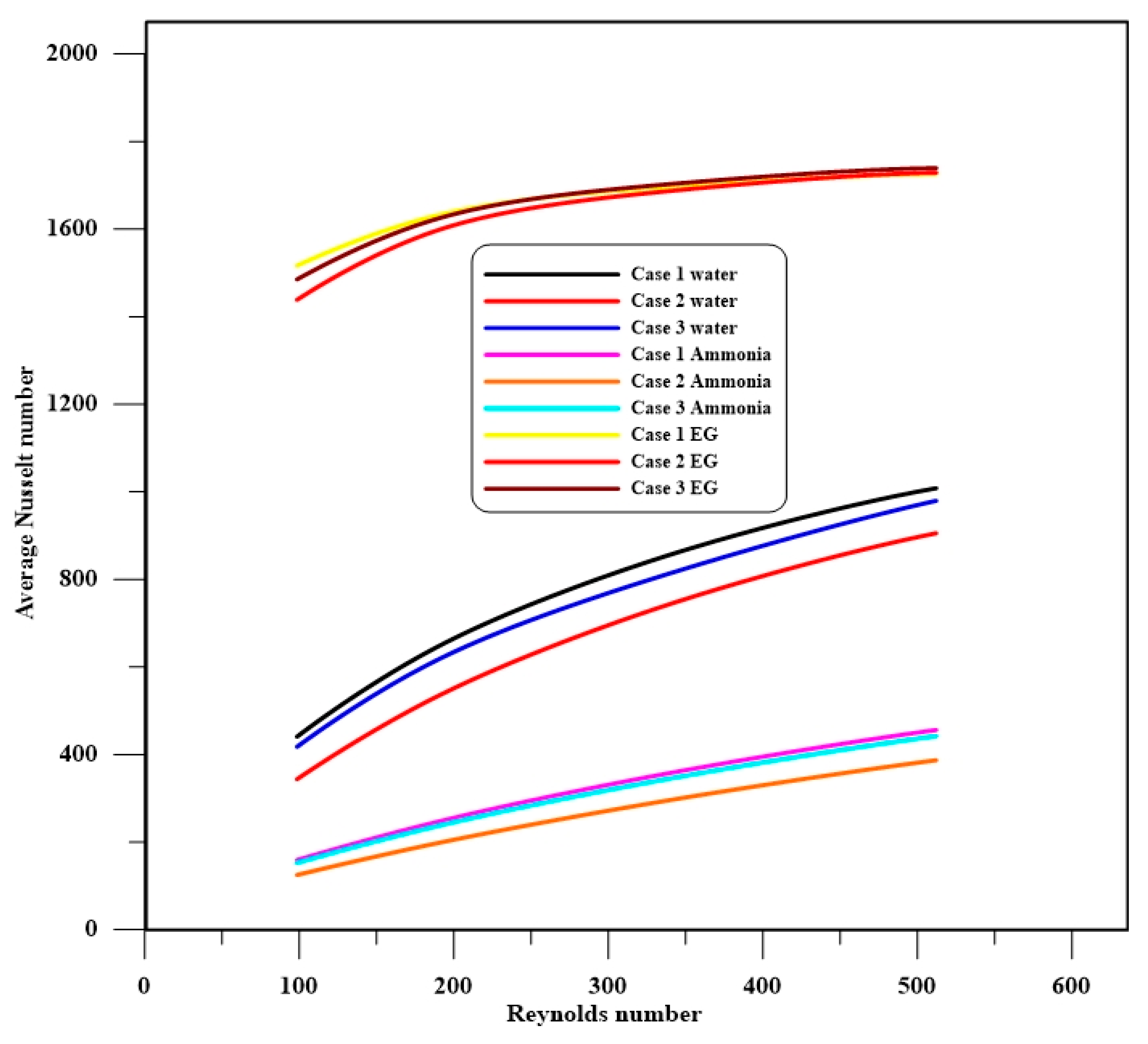
Figure 3a–c display the profile of the local Nusselt number versus different Reynolds numbers for three types of fluids (water, ammonia liquid and EG) for case 1. The results show that the local Nusselt number increases with rising Re. The critical effects are seen at the entrance area of the first and second steps, which are represented by sudden increments in value, with two peaks on the curve. The influences of the step height on the local Nusselt number for all the types of studied fluids at Re = 512 are depicted in Figure 4a–c. The findings indicate that the local Nusselt number is higher in cases 1 and 3 in comparison to case 2. The profile of the average Nusselt number for several cases and Reynolds numbers and all the working fluids is shown in Figure 5a–c. In general, the results demonstrate that the average Nu is higher in case 1 compared to the other cases. Additionally, as evident from Figure 6, the maximum average Nusselt number, which represents the thermal performance, can clearly be seen in case 1 for EG, in comparison to water and ammonia.
4.2. Flow Characteristics
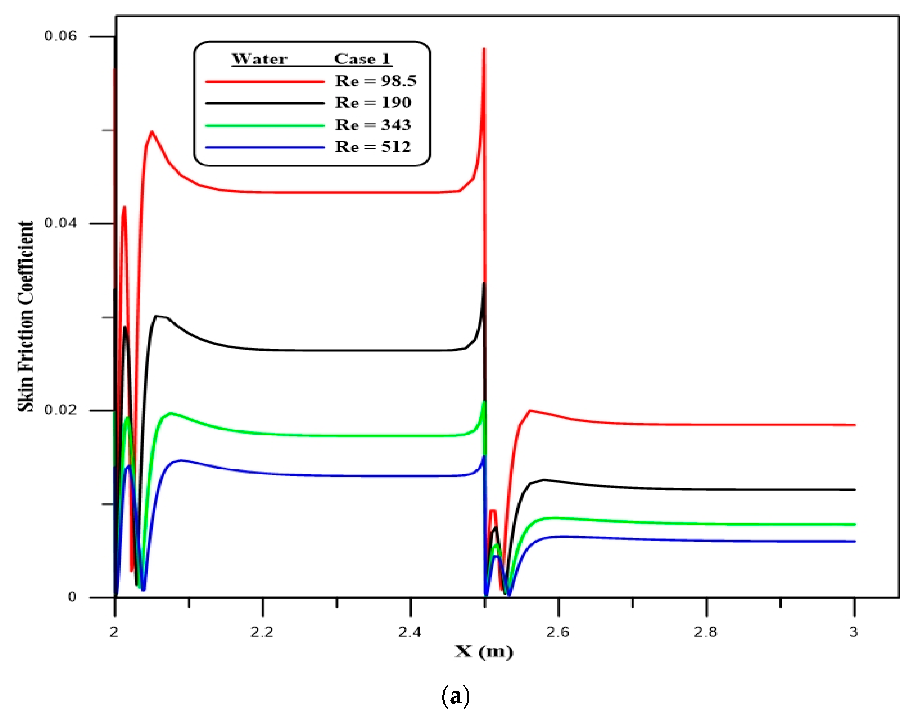
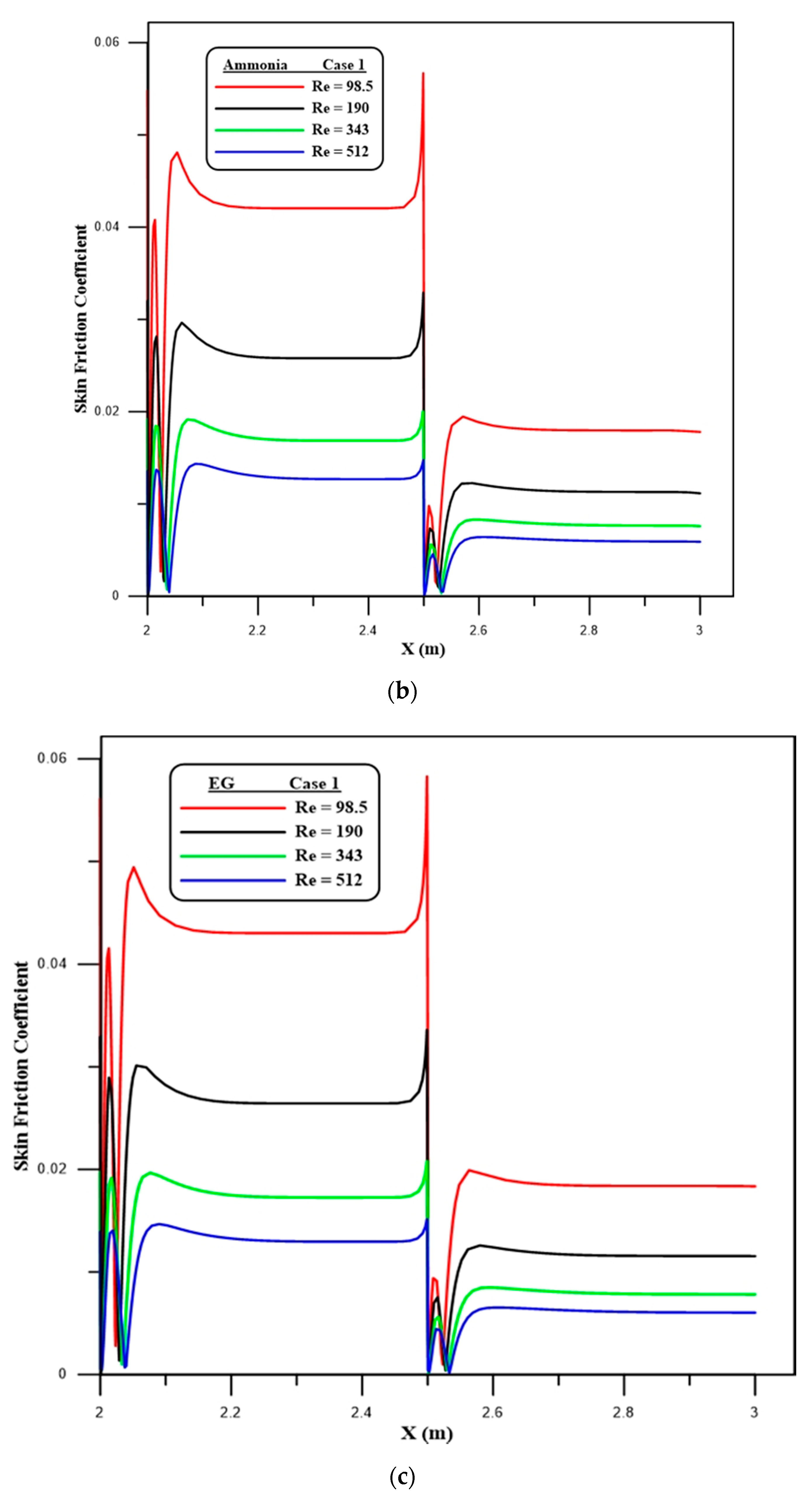
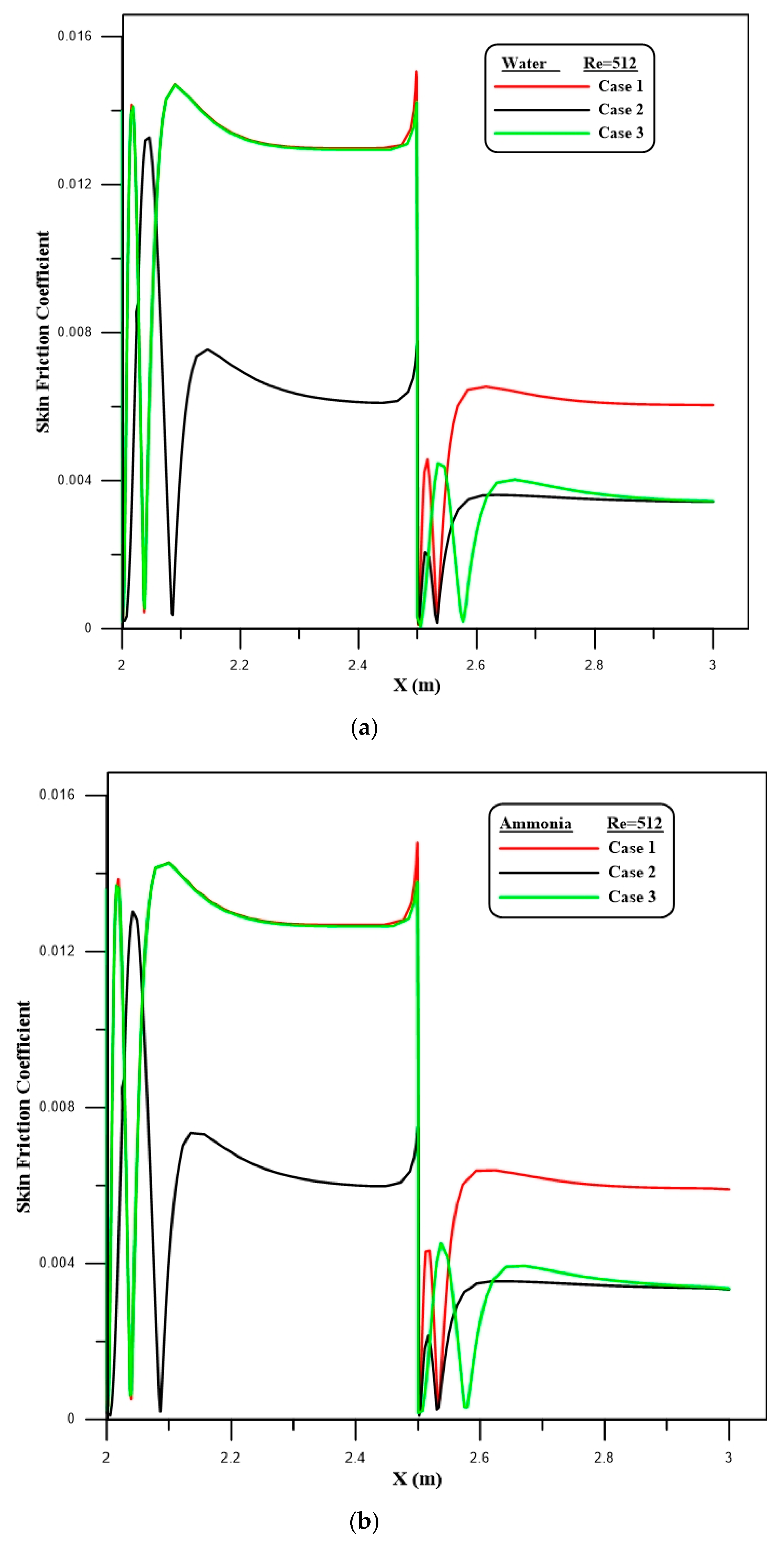
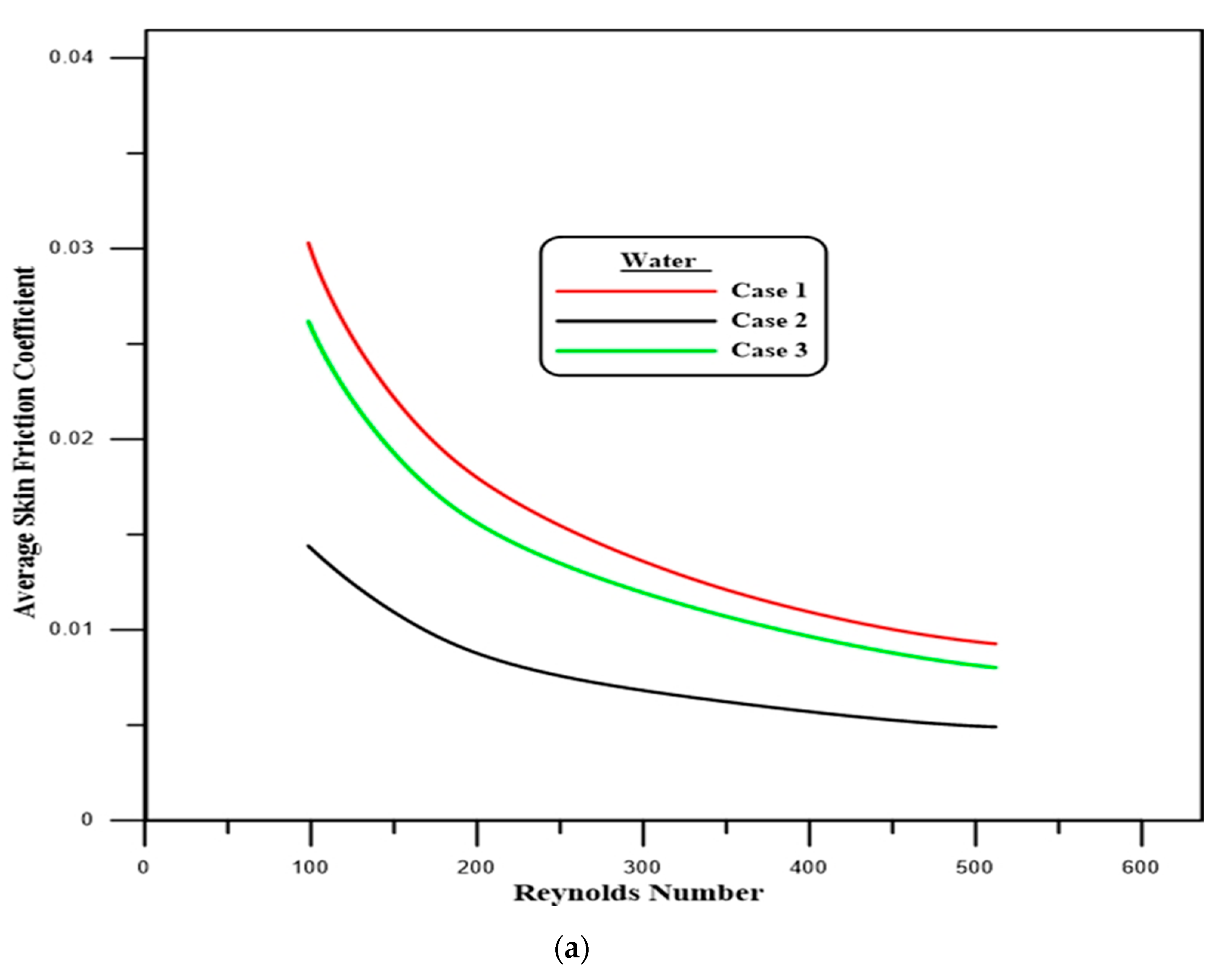
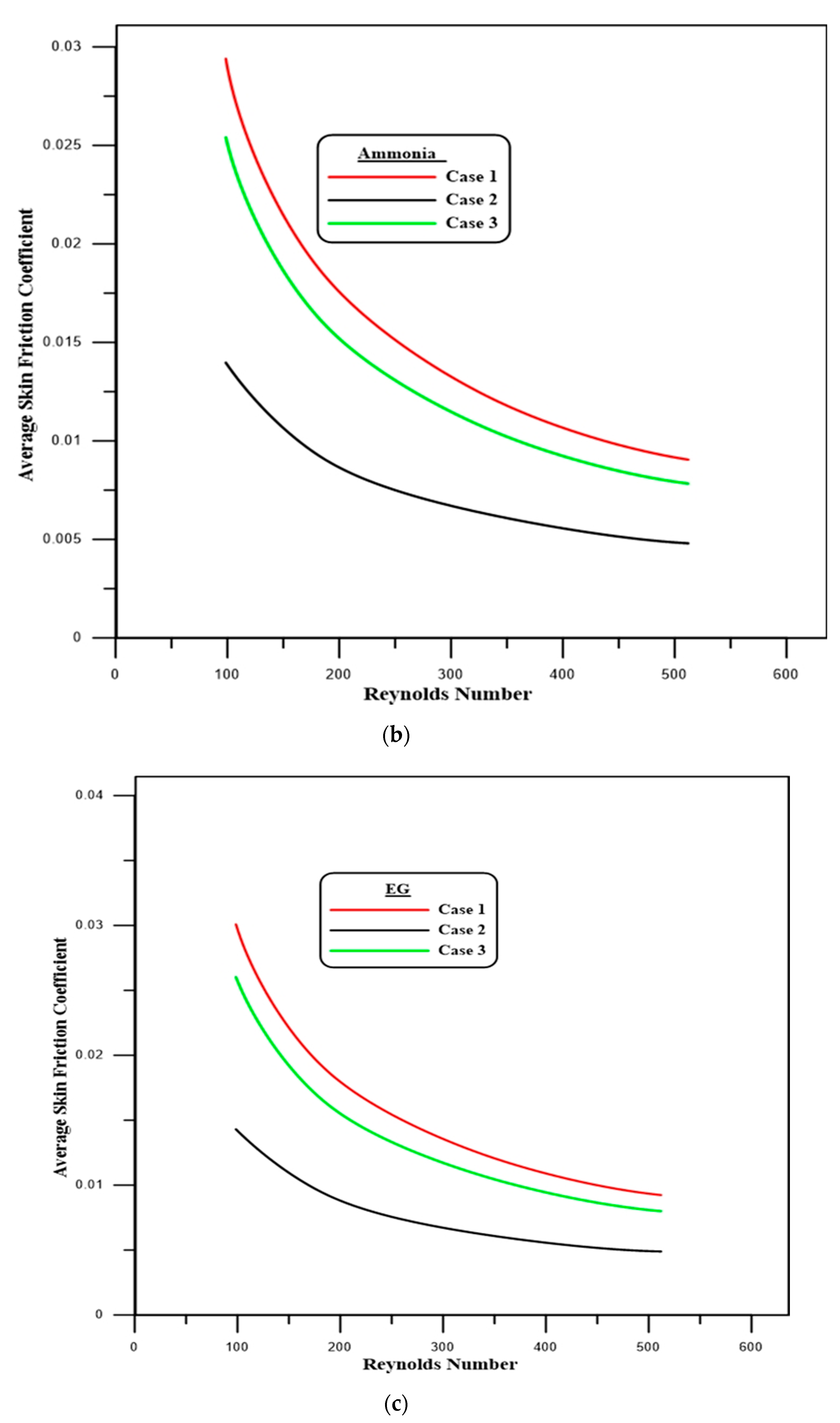
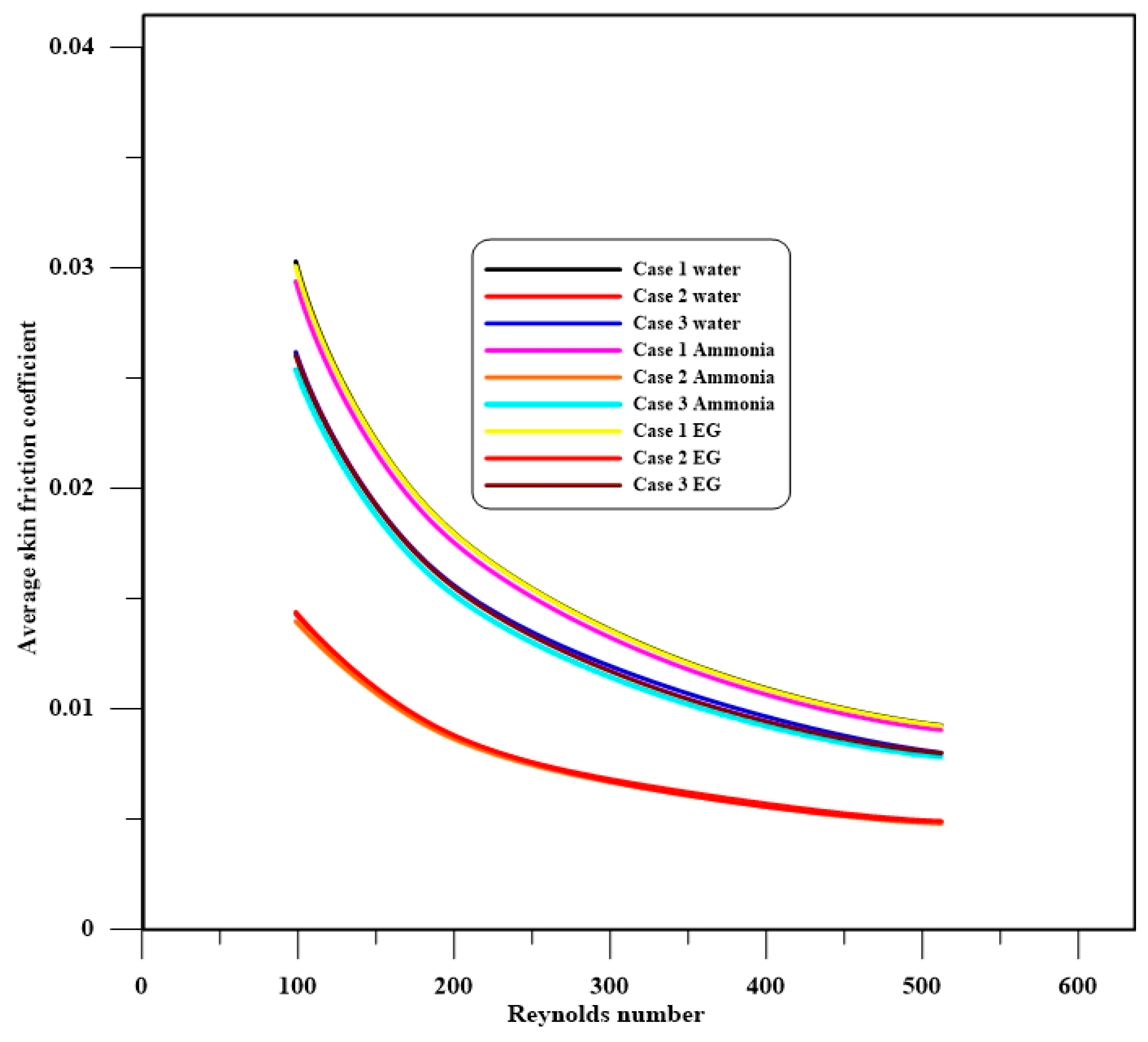
The effects of using the three types of carrying fluids (water, ammonia liquid and EG) with different Reynolds numbers on the local skin friction coefficient for case 1 are represented in Figure 7a–c. A rapid increase in the local skin friction coefficient is observed, especially at the first and second steps of the downstream section, due to the expansion of the passage, which produces the separation flow. Moreover, the results of the present research show that an increase in the Reynolds number can affect the skin friction coefficient. The same trend for the skin friction coefficient is observed in the three studied cases and studied fluids at Re = 512, as depicted in Figure 8a–c. Figure 9a–c show the average skin friction coefficient profile on the downstream wall for the three cases and different Reynolds numbers. The findings specify that the maximum skin friction coefficient is acquired in case 1 for all three carrying fluids. A comparison of the average skin friction coefficient for all the cases with different Reynolds numbers and working fluids is presented in Figure 10. Generally, rises in the rate of the skin friction coefficient are observed with Reynolds number decrements. However, the maximum value is obtained in case 1 for water flow and a Reynolds number of 512.
4.3. Velocity Profile
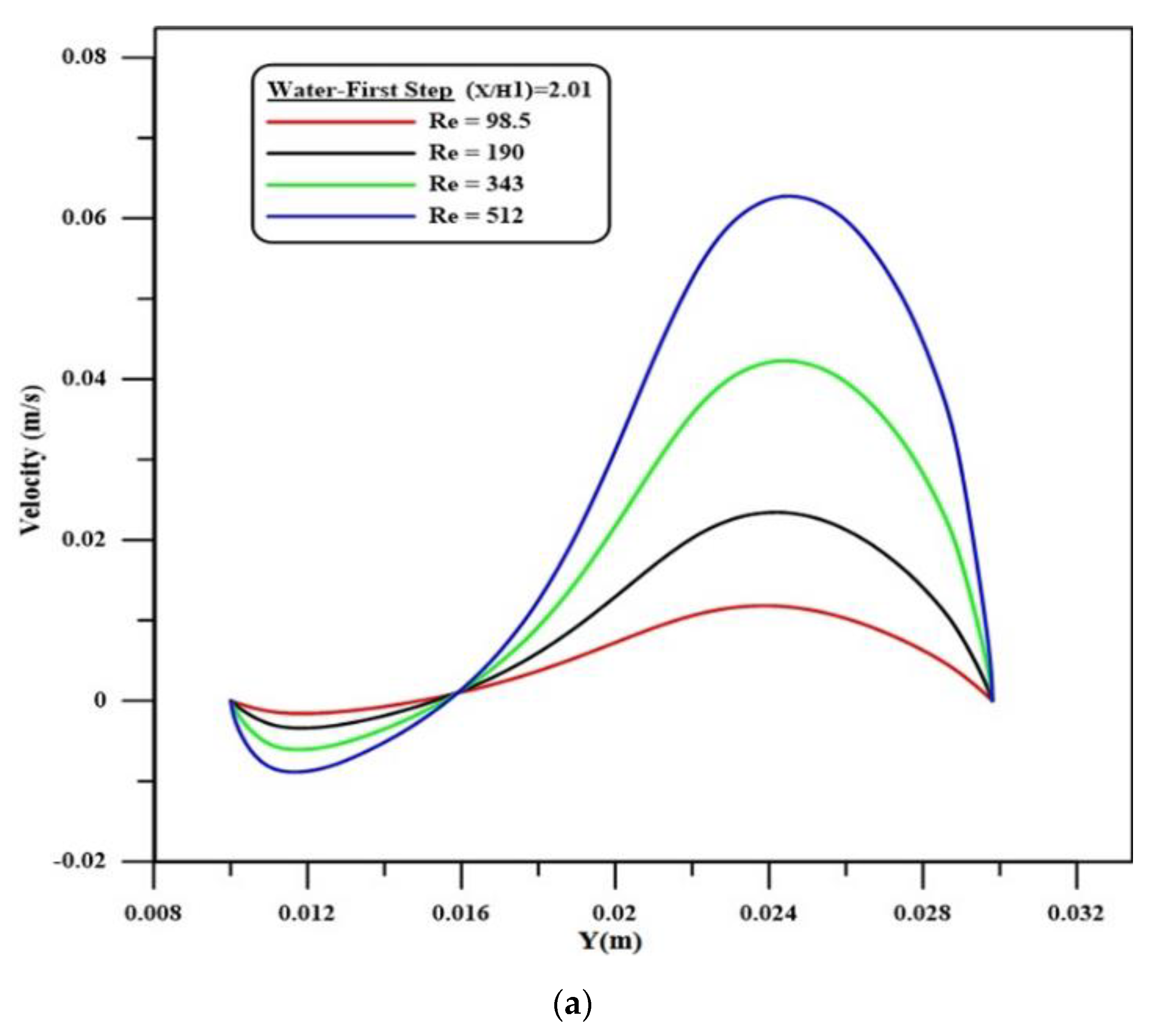
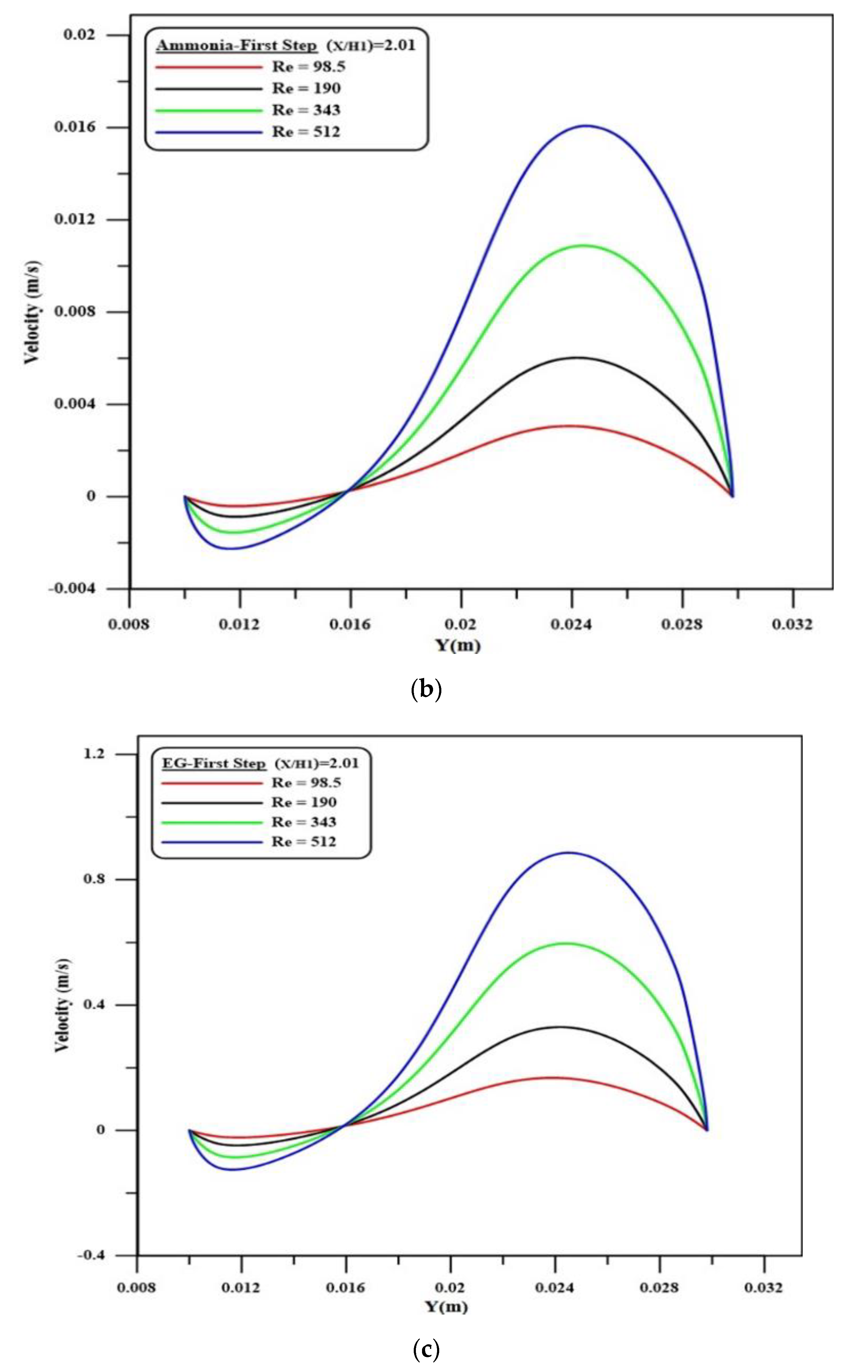
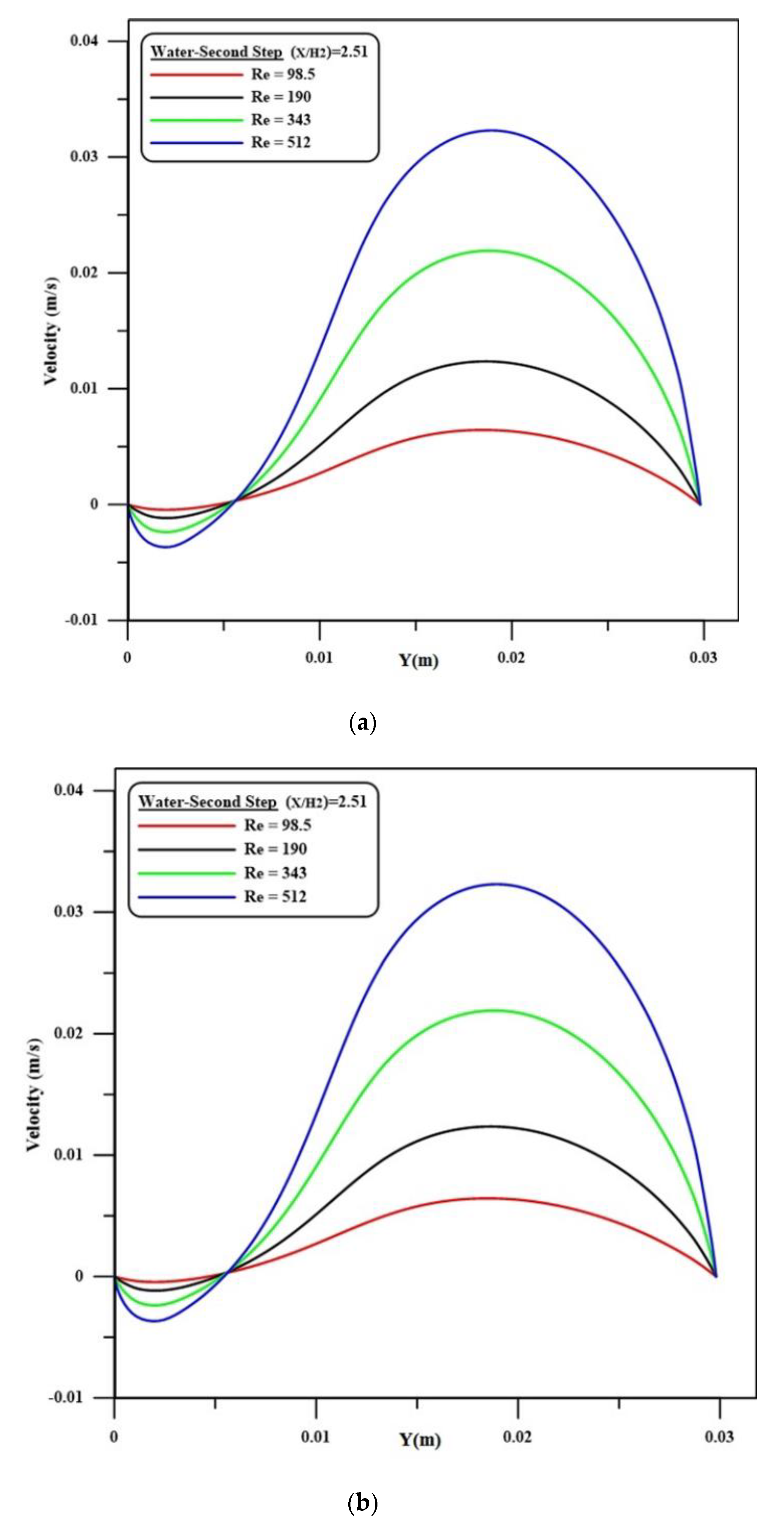
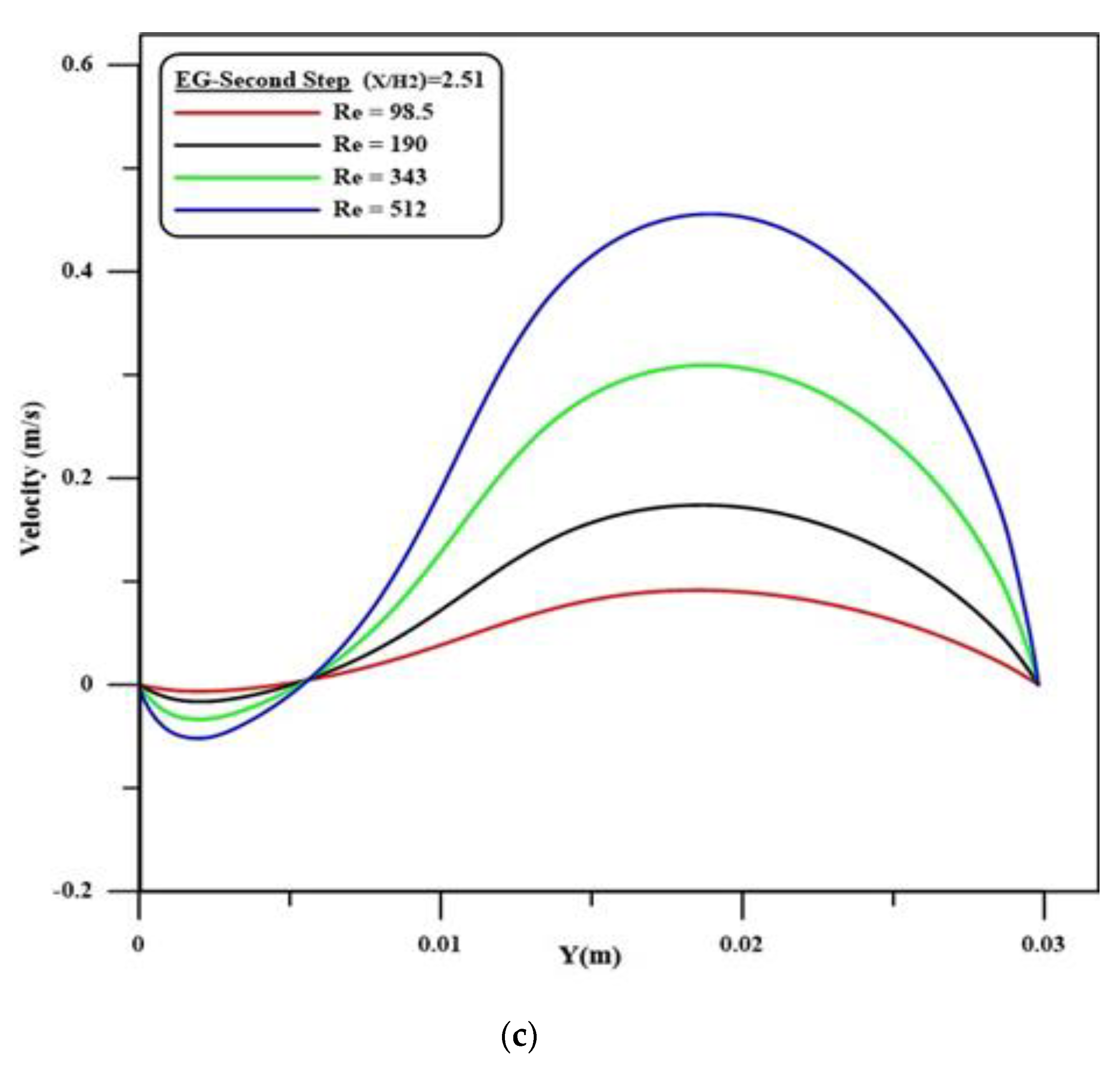
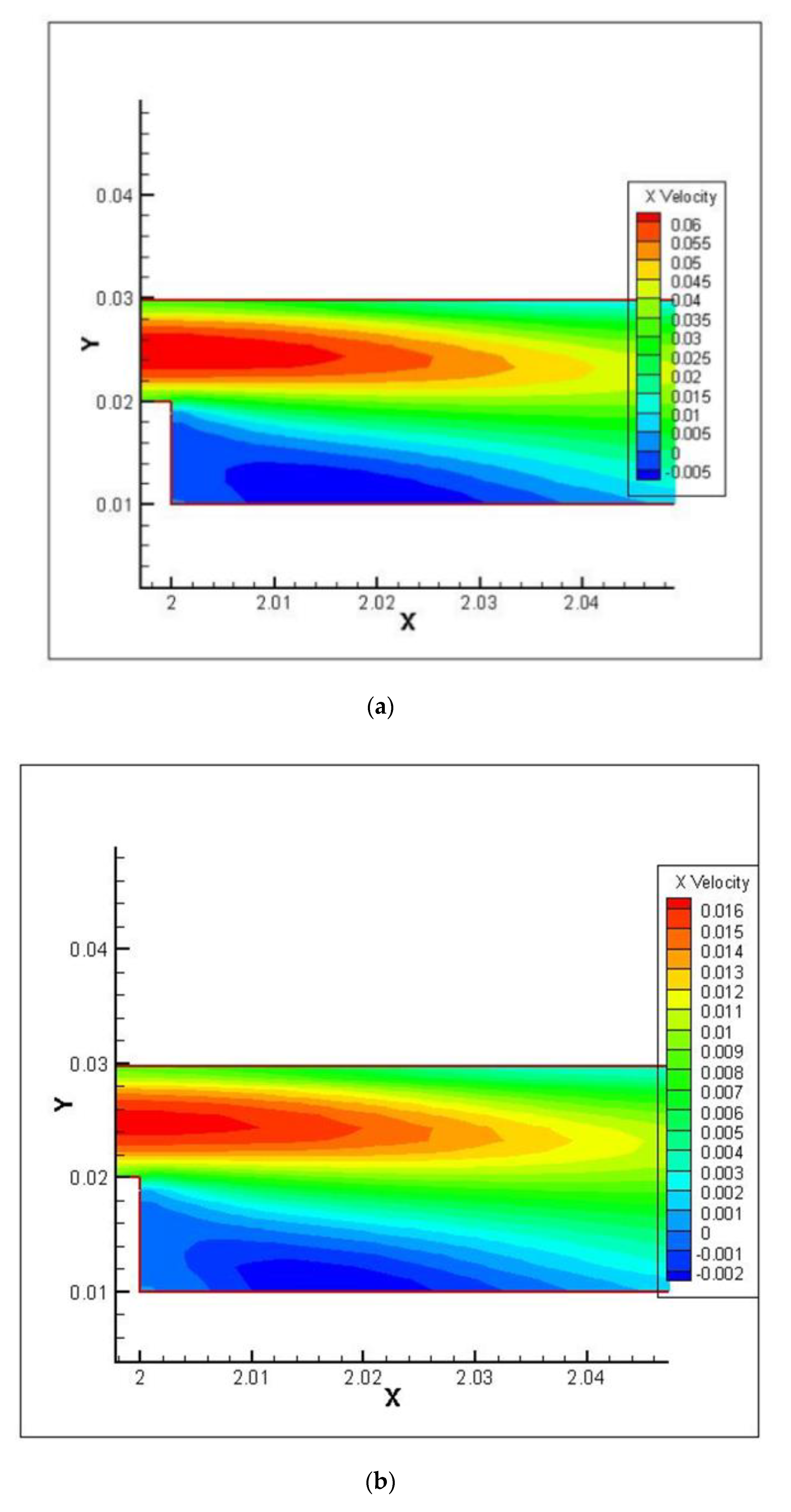
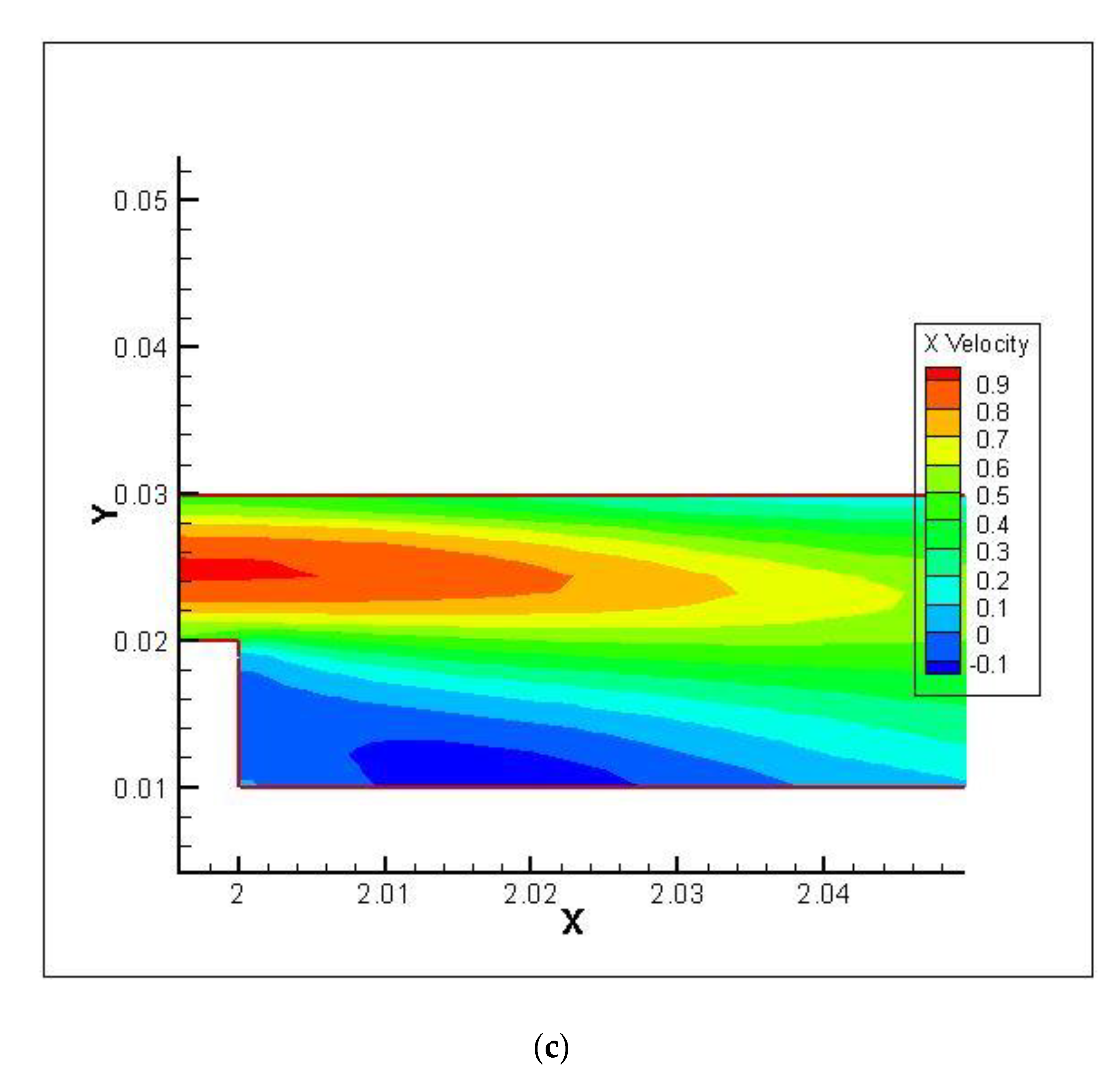
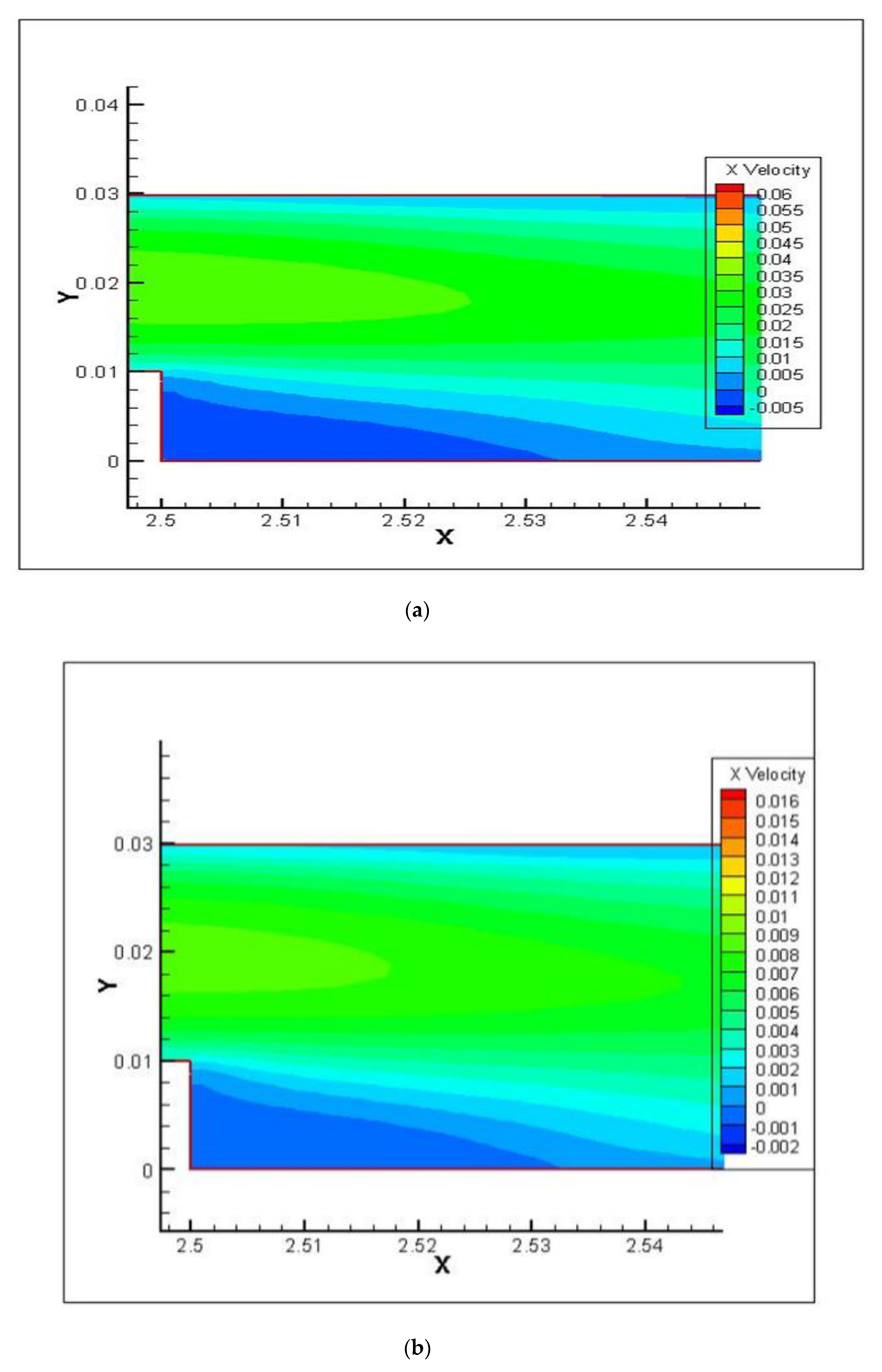
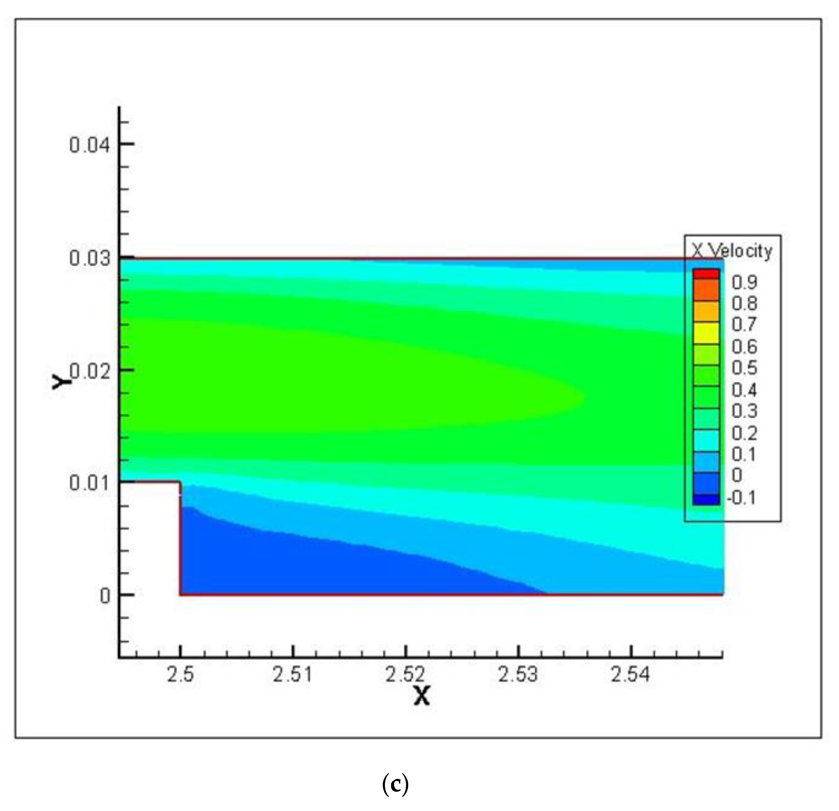
Velocity profiles with positions (X/H1 = 2.01, X/H2 = 2.51) at the first and second steps for all the studied cases are plotted in Figure 11a–c and Figure 12a–c, respectively. It is noted that velocity diminishes at the first and second steps sharply and then increases due to recirculation flow, which is generated at the regions after the first and second steps. The velocity contours at the first and second steps for a Reynolds number of 512 and case 1 are represented in Figure 13 and Figure 14, respectively. The figures demonstrate the recirculation zone at the first and second steps, which show the heat transfer augmentation.
5. Conclusions
This paper investigates the impacts of the step size, Reynolds number and type of liquid on heat transfer enhancement. From the achieved results, the conclusions can be summarized as follows:
- An increase in the local Nusselt number is detected with rises in the Reynolds number, while the critical effects are seen at the start region of the first and second steps.
- The results show that higher local Nusselt numbers occur in cases 1 and 3, compared to case 2, for all types of fluids.
- The maximum average Nusselt number, which represents the thermal performance, can clearly be seen in case 1 for EG, in comparison to water and ammonia.
- A rise in the local skin friction coefficient is apparent at the first and second steps of the downstream section due to the expansion of the passage, which produces the separation flow.
- The velocity decreases rapidly at the first and second steps and then increases. This is due to the recirculation flow, which is generated at the zones after the first and second steps.
Author Contributions
Conceptualization, H.T., T.A., M.G.; methodology, H.T., T.A., H.A.; formal analysis, H.T., T.A., H.A.; investigation, H.T., T.A.; resources, M.G. and M.R.S.; data curation, H.T.; writing—original draft preparation, H.T., H.A.; writing—review and editing, M.G., and M.R.S.; visualization, H.T., T.A., H.A.; supervision, M.G. and M.R.S.; project administration, M.G. and M.R.S. All authors have read and agreed to the published version of the manuscript.
Funding
This research received no external funding.
Conflicts of Interest
The authors declare no conflict of interest.
Nomenclature
| A | Length of the bottom wall before the first step |
| B | Length of the bottom wall after the first step |
| C | Length of the bottom wall after the second step |
| Cp | Specific heat |
| H | Width of the channel at the entrance |
| H1 | The step height of the first step |
| H2 | The step height of the second step |
| L | The total length of the channel |
| Nu | Nusselt number |
| P | Pressure |
| Pr | Prandtl number |
| Re | Reynolds number |
| T | Temperature |
| u, v | Axial velocity |
| X, y | Cartesian coordinates |
| Greek symbols | |
| Ρ | Water density |
| µ | Dynamic viscosity |
References
- Abbott, D.E.; Kline, S.J. Experimental Investigation of Subsonic Turbulent Flow Over Single and Double Backward Facing Steps. J. Basic Eng. 1962, 84, 317–325. [Google Scholar] [CrossRef]
- Goldstein, R.J.; Eriksen, V.L.; Olson, R.M.; Eckert, E.R.G. Laminar Separation, Reattachment, and Transition of the Flow Over a Downstream-Facing Step. J. Basic Eng. 1970, 92, 732–739. [Google Scholar] [CrossRef]
- Armaly, B.F.; Durst, F.; Pereira, J.C.; Schönung, B. Experimental and theoretical investigation of backward-facing step flow. J. Fluid Mech. 1983, 127, 473. [Google Scholar] [CrossRef]
- Aung, W. An Experimental Study of Laminar Heat Transfer Downstream of Backsteps. J. Heat Transf. 1983, 105, 823–829. [Google Scholar] [CrossRef]
- Abu-Nada, E. Entropy generation due to heat and fluid flow in backward facing step flow with various expansion ratios. Int. J. Exergy 2006, 3, 419. [Google Scholar] [CrossRef] [Green Version]
- Abu-Mulaweh, H. A review of research on laminar mixed convection flow over backward- and forward-facing steps. Int. J. Therm. Sci. 2003, 42, 897–909. [Google Scholar] [CrossRef]
- Sano, M.; Suzuki, I.; Sakuraba, K. Control of Turbulent Channel Flow over a Backward-Facing Step by Suction. J. Fluid Sci. Technol. 2009, 4, 188–199. [Google Scholar] [CrossRef] [Green Version]
- Terhaar, S.; Velazquez, A.; Arias, J.R.; Sánchez-Sanz, M. Experimental study on the unsteady laminar heat transfer downstream of a backwards facing step. Int. Commun. Heat Mass Transf. 2010, 37, 457–462. [Google Scholar] [CrossRef]
- Barkley, D.; Gomes, M.G.M.; Henderson, R.D. Three-dimensional instability in flow over a backward-facing step. J. Fluid Mech. 2002, 473, 167–190. [Google Scholar] [CrossRef] [Green Version]
- Abe, K.; Kondoh, T.; Nagano, Y. A new turbulence model for predicting fluid flow and heat transfer in separating and reattaching flows—I. Flow field calculations. Int. J. Heat Mass Transf. 1994, 37, 139–151. [Google Scholar] [CrossRef]
- Abe, K.; Kondoh, T.; Nagano, Y. A new turbulence model for predicting fluid flow and heat transfer in separating and reattaching flows—II. Thermal field calculations. Int. J. Heat Mass Transf. 1995, 38, 1467–1481. [Google Scholar] [CrossRef]
- Vogel, J.C. Heat Transfer and Fluid Mechanics Measurements in the Turbulent Reattaching Flow behind a Backward-facing Step; Stanford University: Stanford, CA, USA, 1984. [Google Scholar]
- Chiang, T.P.; Sheu, T.W.H. A numerical revisit of backward-facing step flow problem. Phys. Fluids 1999, 11, 862–874. [Google Scholar] [CrossRef]
- Tylli, N.; Ineichen, B.; Kaiktsis, L. Sidewall effects in flow over a backward-facing step: Experiments and numerical simulations. Phys. Fluids 2002, 14, 3835–3845. [Google Scholar] [CrossRef]
- Durst, F.; Pereira, J.C. Time-Dependent Laminar Backward-Facing Step Flow in a Two-Dimensional Duct. J. Fluids Eng. 1988, 110, 289–296. [Google Scholar] [CrossRef]
- Biswas, G.; Breuer, M.; Durst, F. Backward-Facing Step Flows for Various Expansion Ratios at Low and Moderate Reynolds Numbers. J. Fluids Eng. 2004, 126, 362–374. [Google Scholar] [CrossRef]
- Öztop, H.F.; Mushatet, K.S.; Yılmaz, I.; Yilmaz, I. Analysis of turbulent flow and heat transfer over a double forward facing step with obstacles. Int. Commun. Heat Mass Transf. 2012, 39, 1395–1403. [Google Scholar] [CrossRef]
- Hussein, T.; Abu-Mulaweh, H.I.; Kazi, S.N. A Badarudin. Numerical simulation of heat transfer and separation Al2O3/nanofluid flow in concentric annular pipe. Int. Commun. Heat Mass Transf. 2016, 71, 108–117. [Google Scholar]
- Mehrez, Z.; El Cafsi, A. Forced convection magnetohydrodynamic Al2O3–Cu/water hybrid nanofluid flow over a backward-facing step. J. Therm. Anal. Calorim. 2018, 135, 1417–1427. [Google Scholar] [CrossRef]
- Togun, H.; Abdulrazzaq, T.; Kazi, S.; Badarudin, A. Augmented of turbulent heat transfer in an annular pipe with abrupt expansion. Therm. Sci. 2016, 20, 1621–1632. [Google Scholar] [CrossRef] [Green Version]
- Alrashed, A.A.; Akbari, O.A.; Heydari, A.; Toghraie, D.; Zarringhalam, M.; Shabani, G.A.S.; Seifi, A.R.; Goodarzi, M. The numerical modeling of water/FMWCNT nanofluid flow and heat transfer in a backward-facing contracting channel. Phys. B Condens. Matter. 2018, 537, 176–183. [Google Scholar] [CrossRef]
- Togun, H.; Tuqa, A.; Kazi, S.N.; Badarudin, A.; Ariffin, M.K.A. Heat transfer to laminar flow over a double backward-facing step. Int. J. Mech. Aerosp. Manuf. Ind. Sci. Eng. World Acad. Sci. Eng. Technol. 2013, 10, 1742–1747. [Google Scholar]
- Abdulrazzaq, T.; Togun, H.; Goodarzi, M.; Kazi, S.N.; Ariffin, M.K.A.; Adam, N.M.; Hooman, K. Turbulent heat transfer and nanofluid flow in an annular cylinder with sudden reduction. J. Therm. Anal. Calorim. 2020, 141, 373–385. [Google Scholar] [CrossRef]
- Abdulrazzaq, T.; Hussein, T.; Ariffin, M.K.A.; Kazi, S.N.; Badarudin, A.; Adam, N.M.; Masuri, S. Heat Transfer and Turbulent Fluid Flow over Vertical Double Forward-Facing Step. World Acad. Sci. Eng. Technol. 2014, 8, 722–726. [Google Scholar]
- Rao, A.N.; Zhang, J.; Minelli, G.; Basara, B.; Krajnović, S. Qualitative assessment of the bi-stable states in the wake of a finite-width double backward facing step. J. Wind. Eng. Ind. Aerodyn. 2019, 186, 241–249. [Google Scholar] [CrossRef] [Green Version]
- Hussein, H. Laminar CuO–water nanofluid flow and heat transfer in a backward-facing step with and without obstacle. Appl. Nanosci. 2016, 6, 371–378. [Google Scholar]
- Salman, S.; Abu Talib, A.; Saadon, S.; Sultan, M.H. Hybrid nanofluid flow and heat transfer over backward and forward steps: A review. Powder Technol. 2020, 363, 448–472. [Google Scholar] [CrossRef]
- Hussein, T.; Safaei, M.R.; Sadri, R.; Kazi, S.N.; Homoon, K.; Sadeghinezhad, E. Heat transfer to turbulent and laminar Cu/water flow over a backward-facing step. Appl. Math. Comput. 2014, 239, 153–170. [Google Scholar]
- Ehsan, K.A.; Mohammad, B.A.; Javad Abolfazli, E. Simulation of rarefied gas flow in a microchannel with backward facing step by two relaxation times using Lattice Boltzmann method—Slip and transient flow regime. Int. J. Mech. Sci. 2019, 157, 802–815. [Google Scholar]
- Togun, H.; Kazi, S.; Badarudin, A. Turbulent heat transfer to separation nanofluid flow in annular concentric pipe. Int. J. Therm. Sci. 2017, 117, 14–25. [Google Scholar] [CrossRef]
- Sadeq, S.; Abd Rahim, A.T.; Ali, H.; Sadeq, R.N.; Mohamed, T.H.S.; Syamimi, S. Numerical study on the turbulent mixed convection heat transfer over 2D Microsclae backward facing step. CFD Lett. 2019, 11, 31–45. [Google Scholar]
- Abdulrazzaq, T.; Togun, H.; Reza, S.M.; Kazi, S.N.; Ariffin, M.; Adam, N.M.; Safaei, M.R. Effect of flow separation of TiO2 nanofluid on heat transfer in the annular space of two concentric cylinders. Therm. Sci. 2020, 24, 1007–1018. [Google Scholar] [CrossRef] [Green Version]
- Bala, S.K.; Saha, L.K.; Hossain, M.A. Simulation of Forced Convection in a Channel Containing Three Obstacles over Backward and Forward Facing Steps by LBM. Int. J. Appl. Comput. Math. 2019, 5, 35. [Google Scholar] [CrossRef]
- Yuan, M.; Rasul, M.; Mohammad, M.R.; Zhigang, Y.; Yuhao, F. Baffle and geometry effects on nanofluid forced convection over forward- and backward-facing steps channel by means of lattice Boltzmann method. Phys. A Stat. Mech. Appl. 2020, 554, 124696. [Google Scholar]
- Fetta, D.; Ahlem, B.; Omar, M.; Seif-Eddine, O.; Nabila, L.; Youb Khaled, B. Effect of backward facing step shape on 3D mixed convection of Bingham fluid. Int. J. Therm. Sci. 2020, 147, 106116. [Google Scholar]
- Jure, O.; Iztok, T.; Wadim, J.; Thomas, S.; Wolfgang, H.; Ivan, O.; Afaque, S. Thermal fluctuations in low-Prandtl number fluid flows over a backward facing step. Nucl. Eng. Des. 2020, 359, 110460. [Google Scholar]
- Safaei, M.R.; Togun, H.; Vafai, K.; Kazi, S.N.; Badarudin, A. Investigation of Heat Transfer Enhancement in a Forward-Facing Contracting Channel Using FMWCNT Nanofluids. Numer. Heat Transf. Part A Appl. 2014, 66, 1321–1340. [Google Scholar] [CrossRef]
- Karimipour, A.; Esfe, M.H.; Safaei, M.R.; Semiromi, D.T.; Jafari, S.; Kazi, S. Mixed convection of copper–water nanofluid in a shallow inclined lid driven cavity using the lattice Boltzmann method. Phys. A Stat. Mech. Appl. 2014, 402, 150–168. [Google Scholar] [CrossRef]
- Armaly, B.; Li, A.; Nie, J. Measurements in three-dimensional laminar separated flow. Int. J. Heat Mass Transf. 2003, 46, 3573–3582. [Google Scholar] [CrossRef]
Figure 1.
Schematic diagram.

Figure 2.
Velocity profile at different positions for (a) X/S = 1, (b) X/S = 3, (c) X/S = 5 and (d) X/S = 7.
Figure 2.
Velocity profile at different positions for (a) X/S = 1, (b) X/S = 3, (c) X/S = 5 and (d) X/S = 7.

Figure 3.
Distributions of Nu at different Re for (a) water, (b) ammonia and (c) EG.

Figure 4.
The effect of the step height on local Nusselt number at Re = 512 for (a) water, (b) ammonia and (c) EG.
Figure 4.
The effect of the step height on local Nusselt number at Re = 512 for (a) water, (b) ammonia and (c) EG.


Figure 5.
Comparison of average Nu for (a) water, (b) ammonia and (c) EG.


Figure 6.
Variations of average Nu with different Re.

Figure 7.
Distributions of Cf with different Reynolds numbers for (a) water, (b) ammonia and (c) EG.
Figure 7.
Distributions of Cf with different Reynolds numbers for (a) water, (b) ammonia and (c) EG.


Figure 8.
The effect of the step height on Cf at Re = 512 for (a) water, (b) ammonia and (c) EG.


Figure 9.
Comparison of average Cf with different Re and step heights for (a) water, (b) ammonia and (c) EG.
Figure 9.
Comparison of average Cf with different Re and step heights for (a) water, (b) ammonia and (c) EG.


Figure 10.
Variations of average Cf with different Re.

Figure 11.
Velocity profile at the first step for (a) water, (b) ammonia and (c) EG.


Figure 12.
The velocity profile at the second step for (a) water, (b) ammonia and (c) EG.


Figure 13.
Velocity contour at the first step and Re = 512 for (a) water, (b) ammonia and (c) EG.


Figure 14.
Velocity contour at the second step and Re = 512 for (a) water, (b) ammonia and (c) EG.


Table 1.
Dimensions of geometry.
| Cases | H (cm) | H1 (cm) | H2 (cm) | a (cm) | b (cm) | c (cm) |
|---|---|---|---|---|---|---|
| 1 | 0.98 | 1 | 1 | 200 | 50 | 50 |
| 2 | 0.98 | 2 | 1 | 200 | 50 | 50 |
| 3 | 0.98 | 1 | 2 | 200 | 50 | 50 |
Table 2.
Thermophysical properties of the working fluids.
| Fluid Type | ρ (kg/m3) | μ (N s/m2) | k (W/m K) | Cp (J/kg K) |
|---|---|---|---|---|
| Ammonia (liquid) | 650 | 0.000152 | 0.493 | 4758 |
| EG | 1111.4 | 0.0157 | 0.252 | 2415 |
| Water | 998.2 | 0.001003 | 0.6 | 4182 |
© 2020 by the authors. Licensee MDPI, Basel, Switzerland. This article is an open access article distributed under the terms and conditions of the Creative Commons Attribution (CC BY) license (http://creativecommons.org/licenses/by/4.0/).
Share and Cite
MDPI and ACS Style
Abdulrazzaq, T.; Togun, H.; Alsulami, H.; Goodarzi, M.; Safaei, M.R. Heat Transfer Improvement in a Double Backward-Facing Expanding Channel Using Different Working Fluids. Symmetry 2020, 12, 1088. https://doi.org/10.3390/sym12071088
AMA Style
Abdulrazzaq T, Togun H, Alsulami H, Goodarzi M, Safaei MR. Heat Transfer Improvement in a Double Backward-Facing Expanding Channel Using Different Working Fluids. Symmetry. 2020; 12(7):1088. https://doi.org/10.3390/sym12071088
Chicago/Turabian StyleAbdulrazzaq, Tuqa, Hussein Togun, Hamed Alsulami, Marjan Goodarzi, and Mohammad Reza Safaei. 2020. "Heat Transfer Improvement in a Double Backward-Facing Expanding Channel Using Different Working Fluids" Symmetry 12, no. 7: 1088. https://doi.org/10.3390/sym12071088
Note that from the first issue of 2016, this journal uses article numbers instead of page numbers. See further details here.