Beam Pre-Shaping Methods Using Lenslet Arrays for Area-Based High-Resolution Vehicle Headlamp Systems

Institute of Product Development, Leibniz University Hannover, 30167 Hannover, Germany
*
Author to whom correspondence should be addressed.
†
Current address: Institut für Produktentwicklung und Gerätebau, Gottfried Wilhelm Leibniz Universität Hannover, An der Universität 1, Gebäude 8143, 30823 Garbsen, Germany.
Appl. Sci. 2020, 10(13), 4569; https://doi.org/10.3390/app10134569
Submission received: 9 June 2020
/
Revised: 22 June 2020
/
Accepted: 26 June 2020
/
Published: 1 July 2020
(This article belongs to the Section Optics and Lasers)
Abstract
:High-resolution light distributions are lately in demand for vehicle headlamp systems as an innovative lighting approach. This lighting approach can realize functionalities, such as precise glare avoidance and on-road projection, which are useful for improving traffic comfort and safety. For achieving the required high-resolution light distribution, area-based projection technologies, such as DMD, LCD, and LCoS, are considered to be integrated into such headlamps. These projection devices demand rectangular illumination areas with specific light distributions to fulfill the requirements for illumination efficiency and performance in headlamp systems. Lenslet arrays, based on the principle of Köhler illumination, can effectively homogenize the light and shape it into rectangular shapes simultaneously. Such components are widely used in projection applications. However, they also show functional potentialities to be applied in high-resolution headlamps. This paper explains the design principles and methods of lenslet arrays for beam pre-shaping in headlamp systems. It validates the homogenization using a self-designed and manufactured lenslet array in a demonstrator in the first place. Afterward, this paper introduces two new methods for the centralized beam shaping required by some headlamps. These methods are validated by optical simulations.
1. Introduction
Vehicle headlamps have been undergoing rapid development by researchers and car manufacturers in recent years to improve traffic safety and comfort. The new generation of vehicle headlamp system comes to the high-resolution headlamp, which can provide functionalities, such as precise glare-free high beam and on-road lighting symbol projection [1,2]. On the one hand, a glare-free high beam optimizes the illumination condition for drivers by allowing full-time use of the high beam when driving in the night. At the same time, it can reduce the glaring discomfort by dimming or shutting down the light in specific areas where other traffic participants are [2,3]. On the other hand, on-road projection enables lighting information to be displayed on the road, with which drivers can not only perceive information directly from the road, but also communicate with other road users [2,4,5].
These lighting functionalities require a high-resolution distribution from the headlamp. Because of this reason, area-based light modulator technologies, for example, LCD (liquid crystal display), DMD (digital micromirror device), and LCoS (liquid crystal on silicon) are considered to be integrated into headlamp systems [6,7,8,9,10]. Once these area-based modulator technologies are used, it is essential to have a reliable light shaping method to fulfill the relevant requirements for headlamp systems and achieve a good projection performance simultaneously.
2. Beam Shaping in High-Resolution Headlamp Systems
A modulator-based high-resolution headlamp is composed of the light source, the light modulator, and corresponding optical elements. The light source varies from halogen bulbs, discharge Xenon lamps, LEDs, and laser diodes, emitting light with different specifications and distributions. The light modulators mentioned in Section 1 have rectangular shapes with different aspect ratios. For attaining a good optical efficiency and make full use of the resolution of a modulator, the emitted light from any light source should be pre-shaped to illuminate the light modulator’s active area with a small overfill ratio.
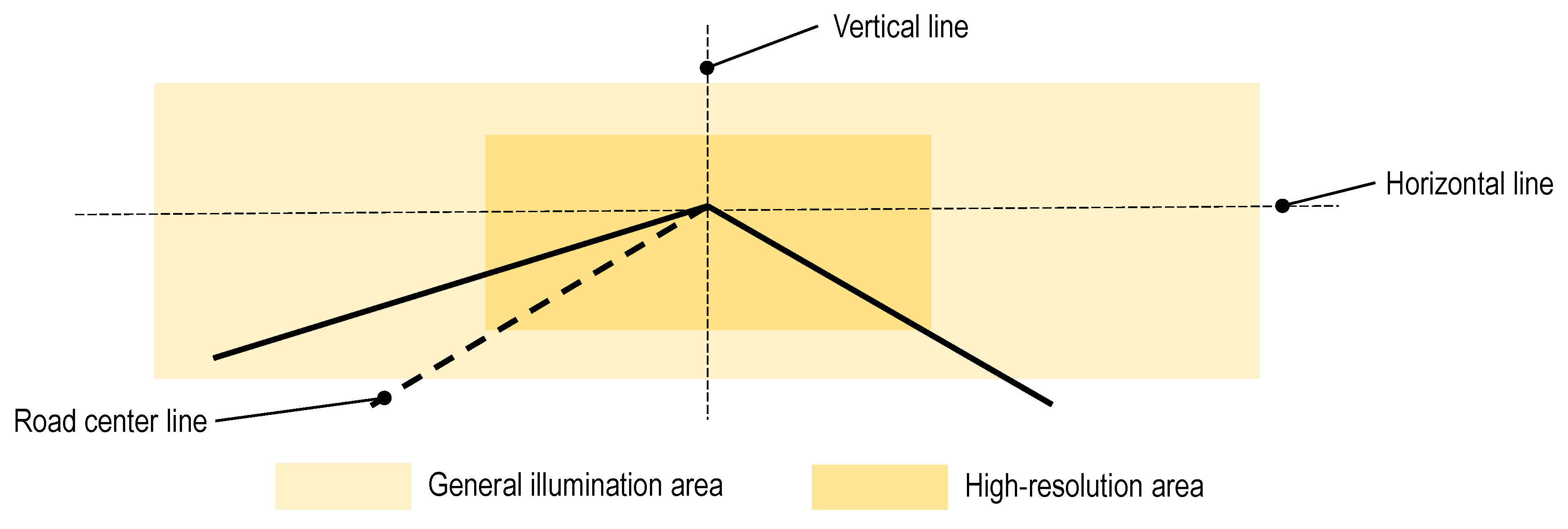
Willeke et al. introduce an LCD headlamp design with RGB (red, green, and blue) laser diodes as the light source in [8]. The laser beams from all diodes are collected and shaped to illuminate the entire LCD surface homogeneously. After that, the projection optics project the transmitted light. Schmidt introduces a concept to supplement a high-resolution module to Mercedes’s multi-beam headlamp [11]. The high-resolution light distribution is generated by a DMD with LEDs as the light source. It can realize the near field homogeneous on-road projection, for example, adverse weather notification. Mercedes has brought this headlamp into the market. The idea of complementing a high-resolution module with a smaller angular range to an entire illumination range is also discussed in [12]. An example of this concept is illustrated in Figure 1 from a driver’s sight.
Besides the homogeneous distribution, there are designs to realize a central hotspot in the illumination pattern. The advantage of this inhomogeneous illumination concerning regulations and system efficiency is discussed in [13,14]. For the inhomogeneous illumination pattern, Günther et al. present an approach that uses an ellipsoid reflector with illumination optics to realize the non-uniform distribution pattern on the DMD surface. Bhakta et al. achieve a similar inhomogeneous pattern using all transparent optics with a white LED [15,16]. Wolf and Pfullmann introduce another optical concept of a DMD-based high-resolution headlamp, in which the DMD chip is homogeneously illuminated, but a pincushion distortion projection lens set is used after the DMD chip to centralize the majority of light in the front center [2,17].
In the above discussed optical concepts of headlamp systems, the light modulators are illuminated by the incident light from the light source either uniformly or non-uniformly. Beam pre-shaping methods before the modulator are requisite in order to achieve the designs of different headlamp systems. It is also necessary to make a good optical efficiency and the lighting performance of the high-resolution headlamps’ functionalities with the pre-shaping methods.
3. Lenslet Array Homogenizer
LAs (lenslet arrays) are widely used as beam homogenizers in projection applications. The LA homogenizer is based on Köhler illumination principle but is more practical to achieve the homogenous distribution for area-based light modulators. However, an LA can be used not only for light homogenization, but also for customized inhomogeneous beam shaping. This chapter introduces the basic principle of the LA homogenizer. The inhomogeneous beam shaping methods introduced in Section 5 are based on this basic principle.
3.1. Köhler Illumination
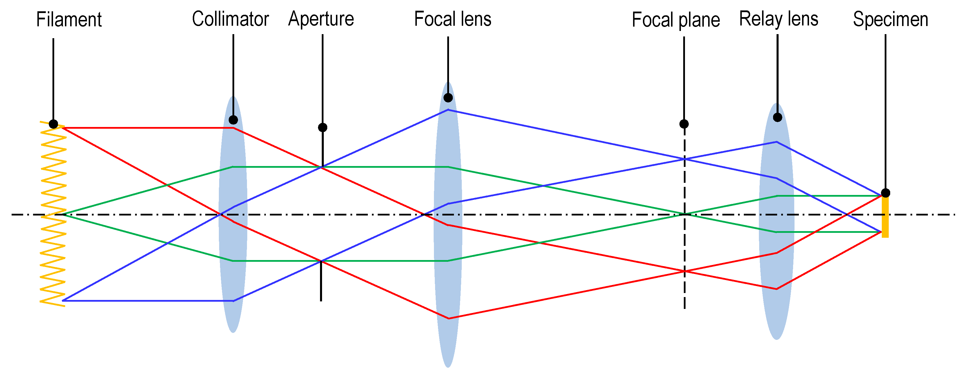
Köhler illumination is at earliest used in modern microscopy systems. It can transfer the inhomogeneous light distribution from the light source (a coiled tungsten filament, for instance) in a microscope to a homogeneous illumination pattern on the specimen. Figure 2 shows the principle and a simplified structure of Köhler illumination [18]. It can be seen from the figure that each field of the filament is collimated by the collimation lens and then imaged at a fictitious focal plane in the first place. An aperture is inserted to control the beam size. After the focal plane, a relay lens parallelizes the light from each field to illuminate the whole specimen range. Thus, the entire specimen area is also a superposition range of light from every field of the light source. By doing this, a uniform illumination pattern at the target position can be achieved. Köhler illumination is also used in projection systems to project a film onto a screen homogeneously [19].
3.2. Lenslet Array Homogenization
Although Köhler illumination can effectively provide the homogeneous illumination pattern, it cannot deform the light from any light source into a rectangular shape to match the dimension of the modulator without an aperture. Due to this reason, a basic Köhler illumination structure results in either a waste of light (with an aperture or a more massive illumination range than the modulator surface without an aperture) or partial use of the modulator’s resolution (a smaller illumination range than the modulator surface). Therefore, another method for simultaneously shaping and homogenizing light is needed.
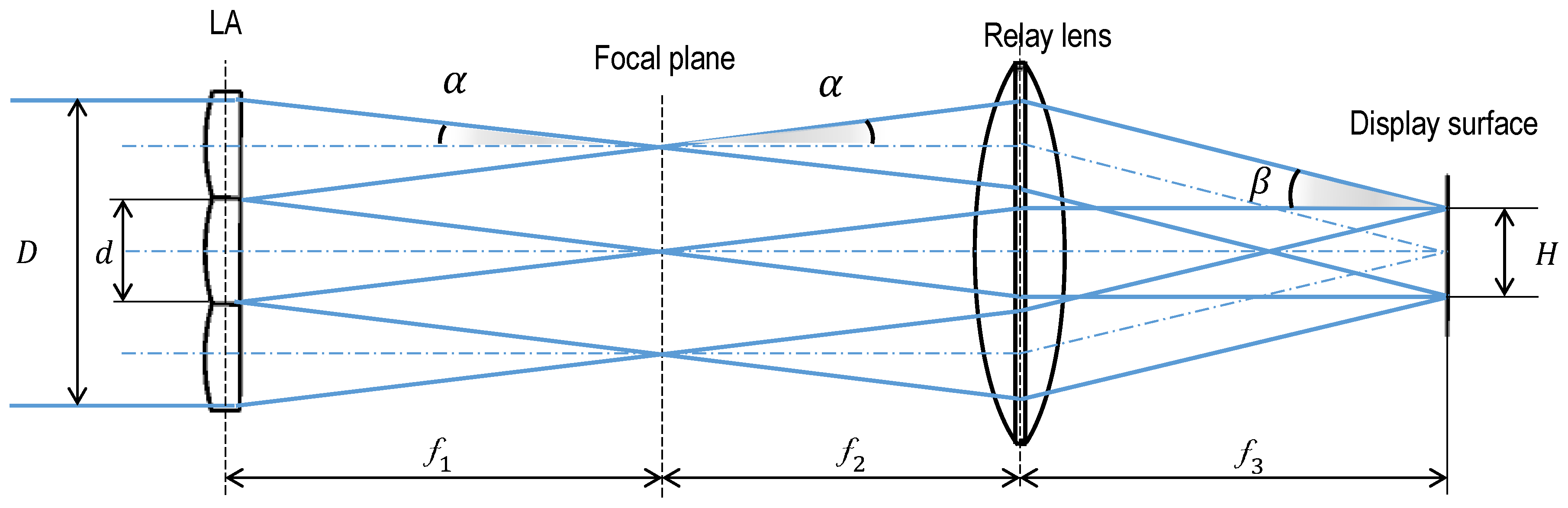
For this purpose, LAs, which are based on Köhler illumination principle, can be applied in such headlamp systems. An LA homogenizer is constituted of a LA with a conventional lens [20]. The LA has multiple lenslets with identical dimensions, so that it firstly separates the incident light into beamlets and focus each beamlet on a focal plane. After that, the conventional lens located at the distance of its focal length with respect to the focal plane acts as the relay lens, as in Köhler illumination systems to collimate each beamlet and converge all parallel beam bundles in the homogenization plane. This homogenization plane is namely the display surface of the light modulator, and it is situated at the focal plane of the relay lens on the opposite side to the LA. Thus, each lenslet with the relay lens is working as an independent Köhler illumination system. A one-dimensional illustration of an LA homogenizer with the interplay of the geometry relationships is shown in Figure 3.
On the left side of the focal plane in Figure 3, D represents the width of the incident beam in this dimension, d represents the dimension of each lenslet, and is the focal length of each lenslet. The interplay of these parameters is:
On the right side of the focal plane, the focal length can be determined once the dimension of the display surface of a modulator H is known. It can be calculated by:
For different lighting modulators, there are different requirements on the incident angles on the modulator surface. An appropriate incident angle helps the modulator to have a good efficiency and modulating performance [21,22]. Once this incident angle is pre-defined, assuming n is the minimum number of lenslets to cover the incident beam, the focal length on the modulator side can be calculated, as below:
For a rectangular lighting modulator that is two-dimensional, s, s and s in both dimensions of the homogenizer are identical, and other geometric quantities of both dimensions can be calculated using Formulas (1)–(3). Therefore, it can be seen that each lenslet on the LA has the same aspect ratio as the modulator’s display surface.
In conclusion, the homogenizer divides the incident beam into multiple sub-beamlets with a specific aspect ratio in the first place. It superposes all of the beamlets on to the modulator with a series of defined geometric quantities. By doing so, both particular beam shaping and homogenization of the incident light can be realized. According to geometric optics, the more lenslets that are covered by the incident light bundle, the more homogeneous the superposition pattern will be.
3.3. The Use of the Second LA
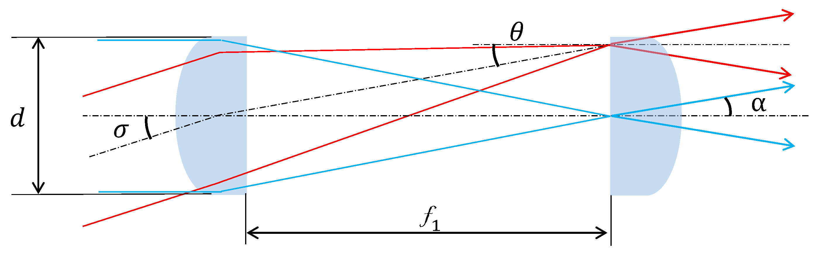
A parallel incident beam is required before the LA to guarantee the desired overlay range, as can be seen from the LA homogenizer’s introduced working principle. However, in actual applications, most light sources cannot be well collimated due to their Étendues [23]. As a result, not all beamlets divided by the LA are superposed within the designed range, but overfill it. This leads to a waste of optical energy in the system. To solve this, a second LA can be applied.
The second array is completely the same as the first, but set oppositely to it at the focal plane of the first LA. Thus, the deviation of the beamlets caused by the initial divergent angle can be revised, so that all beams can be superposed to the same area by the relay lens. Figure 4 shows an illustration of this revision while using a single lenslet from each LA.
Figure 4 illustrates a limitation of applying the second LA. When the incident beam divergence is larger than , this beamlet is no longer focused on the relevant lenslet on the second LA. This situation is detrimental to the beam homogenization. Since the optical system in Figure 4 is approximately a paraxial system, ABCD matrix can be applied to figure out this limitation. The ABCD matrix for the calculation is shown below:
Therefore, when the light emitted from the light source cannot be ideally collimated, an additional LA can complement the homogenization performace. Moreover, in some cases where is not too long, merging the two LAs into one optical element with the thickness of and curvatures on both sides is practical.
4. Validation of Homogenization Principle
A high-resolution luminaire demonstrator is initially set up and presented in this chapter to verify the design approach of the homogenizer for headlamp systems. This demonstrator uses a twisted nematic LCoS as the light modulator and three RGB laser diodes as the light source to realize the white illumination light.
4.1. Simulation
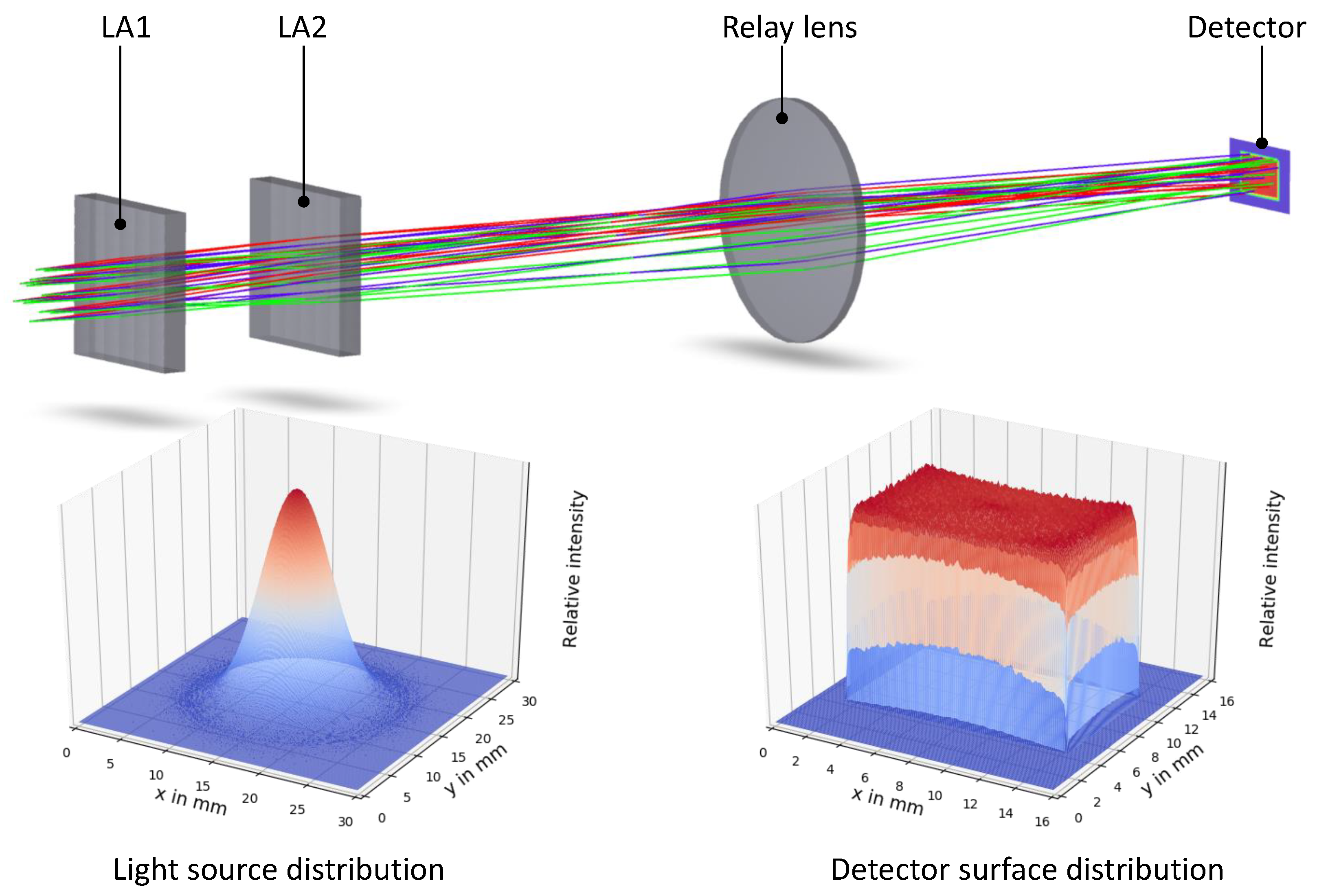
The optical components used in the demonstrator are designed and simulated in Zemax Opticstudio. The laser beams from the RGB laser diodes are firstly collimated, and the beam diameters are expanded to approximately 20 mm. After that, a dichroic prism combines these RGB beams into one white beam. Therefore, this combined incident beam has a quasi-gaussian distribution. It is simulated in Zemax as Gaussian beams with the beam size 6.5 mm at intensity and the divergency of on both horizontal and vertical axes. The light source is set to 20 mm before the LA. Table 1 lists the parameters of the used LCoS.
In order to have a good illumination and projection performance from the LCoS, the incident angle on the LCoS surface is intentionally designed to less than on each direction according to [21]. The principle and geometrical relationships explained in Section 3 are used as the design approach for this demonstrator. The material of the optical components in the simulation model is uncoated PMMA (Polymethyl methacrylate). The clear aperture of each LA is 30 × 30 mm2, on which 60 single-side lenslets are arranged side by side. The simulation model is shown in Figure 5. This figure also shows the light distributions of the incident beam and the detector surface, acting as the LCoS display surface. The combined circular incident beam is shaped into a rectangular shape with the same dimension as the active area of the modulator. The quasi-Gaussian distribution of the incident beam is transformed into a homogeneous distribution eventually. Besides, the incident angles on both horizontal and vertical directions are proven to be less than . Since the requirements on both homogeneity and image sharpness for headlamp systems are not as high as for video projectors, this angle can be slightly larger to have a shorter optical length [10].
According to the simulation result, the optical efficiency of this homogenizer composed of two LAs and a relay lens is . This efficiency represents the part of the light collected within the target illumination area. This collection efficiency goes slightly upward as the initial beam divergency decreases, reaching when the initial incident beam is ideally collimated. Once the second LA is removed, the collection efficiencies drop to and in both cases. Therefore, the second LA makes a considerable contribution to the collection efficiency when the beam from the light source is divergent.
4.2. Prototype Demonstration
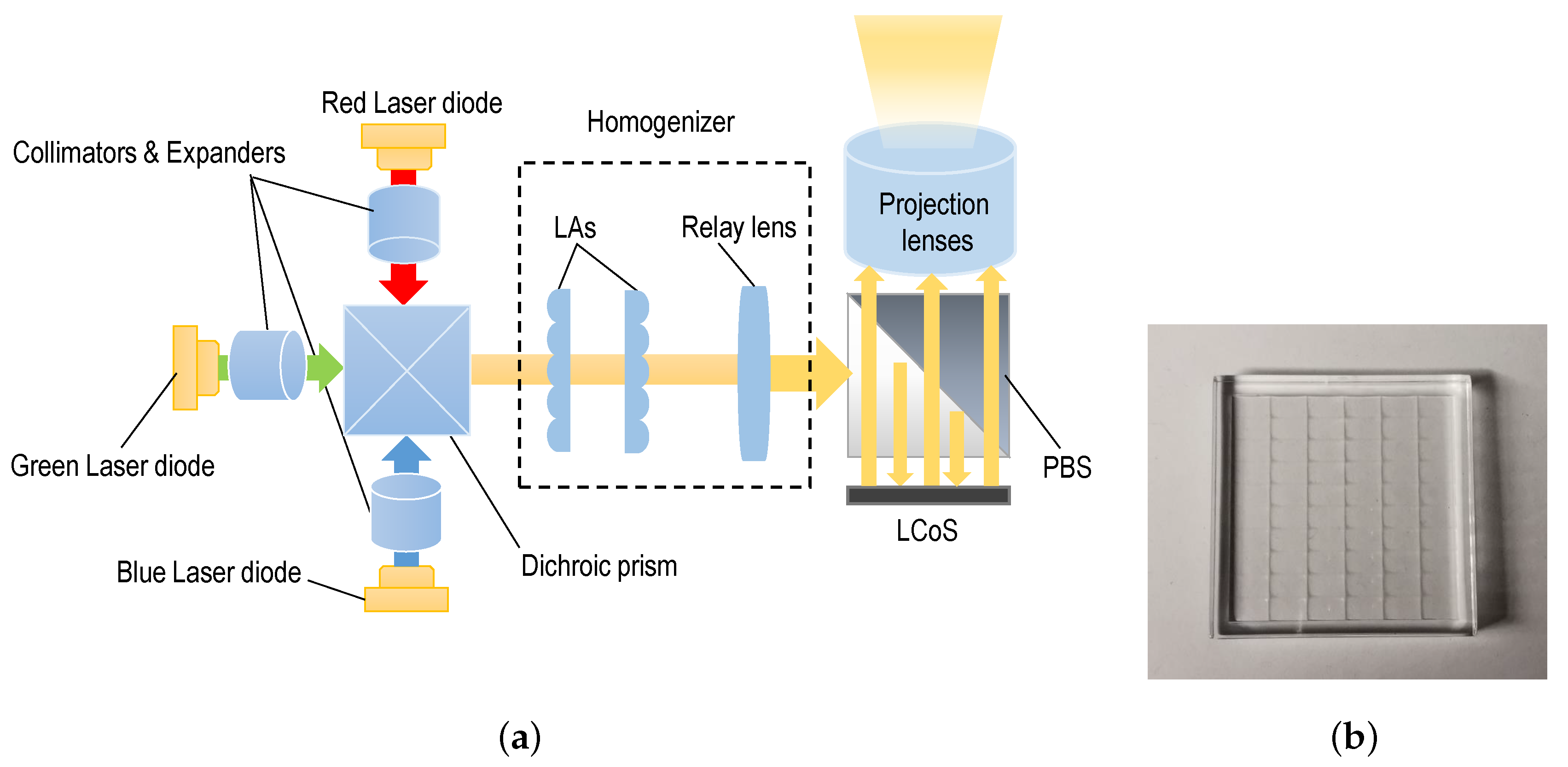
A desktop prototype is set up to investigate the performance of the homogenizer. Three RGB laser diodes (450 nm, 520 nm, 638 nm) are used as the light source with respective collimators and beam expanders for rough pre-shaping, as mentioned in Section 4.1. A dichroic prism is used afterward for the beam combination. Once the laser beams are combined into one joint beam, it goes into the homogenizer. Both the beam expander and the homogenizer components used in the demonstrator are manufactured by an IMES five-Axis milling machine and made of PMMA. After the homogenizer locates the twisted nematic LCoS detailed in Table 1 with a PBS (Polarizing Beam Splitter), which is commonly used in display applications with the LCoS. Finally, a projection lens group projects the light from the LCoS to a measurement screen. Figure 6 shows the demonstrator setup schematic and the manufactured LA.
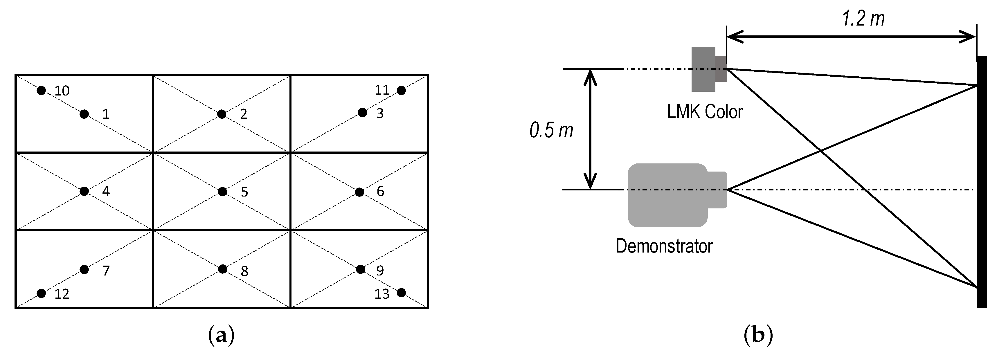
For the evaluation of the homogeneity, the ANSI uniformity standard for evaluating projectors is applied. The whole illumination area is divided into nine parts on average. The center point of each part is the measuring point in terms of the illuminance. In addition, four more measuring points on the corner are taken into account. They are defined as of the distance from the corner to the center point of the entire illumination area. The sampled measuring points are shown in Figure 7. The homogeneity is defined by and , which are the maximum deviation from the average measurements [24]. and can be calculated while using following equations [24,25]:
where and mean the maximum and the minimum illuminance values among points 10–13, respectively. means the average illuminance value among points 1–9.
A lux meter measures the illuminance of these thirteen points, and these values are used to calculate the homogeneity deviations. Besides the illuminance measurement, an LMK color five CCD camera collects the luminance information of the entire illumination area as a reference, so that human eyes can directly observe the illumination result. The measuring setup is also presented in Figure 7.
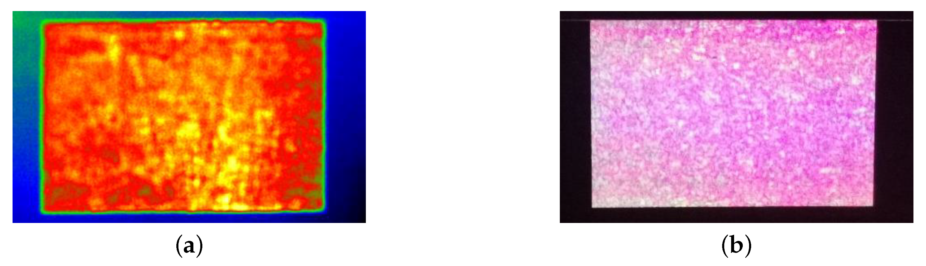
The and values according to Equations (5) and (6) are calculated from the measured illuminance data by the lux meter, which are +5.76%/−6.51%. This result is fully acceptable for illumination from practical experiences, and human eyes can hardly perceive the inhomogeneity. Thus, using LAs as the homogenizer for high-resolution headlamp systems is promising. The measured luminance image from the luminous camera and the photographed projection picture is shown in Figure 8 as a reference. Because of the coherence laser light sources, the illumination on the measuring surface shows an apparent speckle pattern, which also affects the whole homogeneity. When directly using laser beams as the light source in headlamp systems, a further investigation of whether the laser speckle impacts the illumination performance should be made. When necessary, additional optics or vibrators can be considered as complementary elements to the LAs to cope with the speckle pattern [26,27]. Besides the laser speckle, the projection homogeneity is affected by the aperture ratio of the LCoS as well. An LCoS has inter-pixel dead zones, although its aperture ratio is relatively high. These dead zones result in magnifying the intensity of the diffraction orders, leading to inhomogeneous patterns of the projection [28]. This phenomenon is chiefly apparent when the incident light is composed of monochromatic wavelengths.
5. Concepts for Inhomogeneous Beam Shaping
Some vehicle headlamps generate inhomogeneous illumination patterns, as introduced in Section 2. Once the LA homogenizer principle is explained and validated, special inhomogenizers for high-resolution headlamps can be achieved by making modifications on the homogenization principle. This chapter introduces two methods to accomplish these inhomogeneous lighting distributions with central hotspots.
5.1. Modification on Focal Length
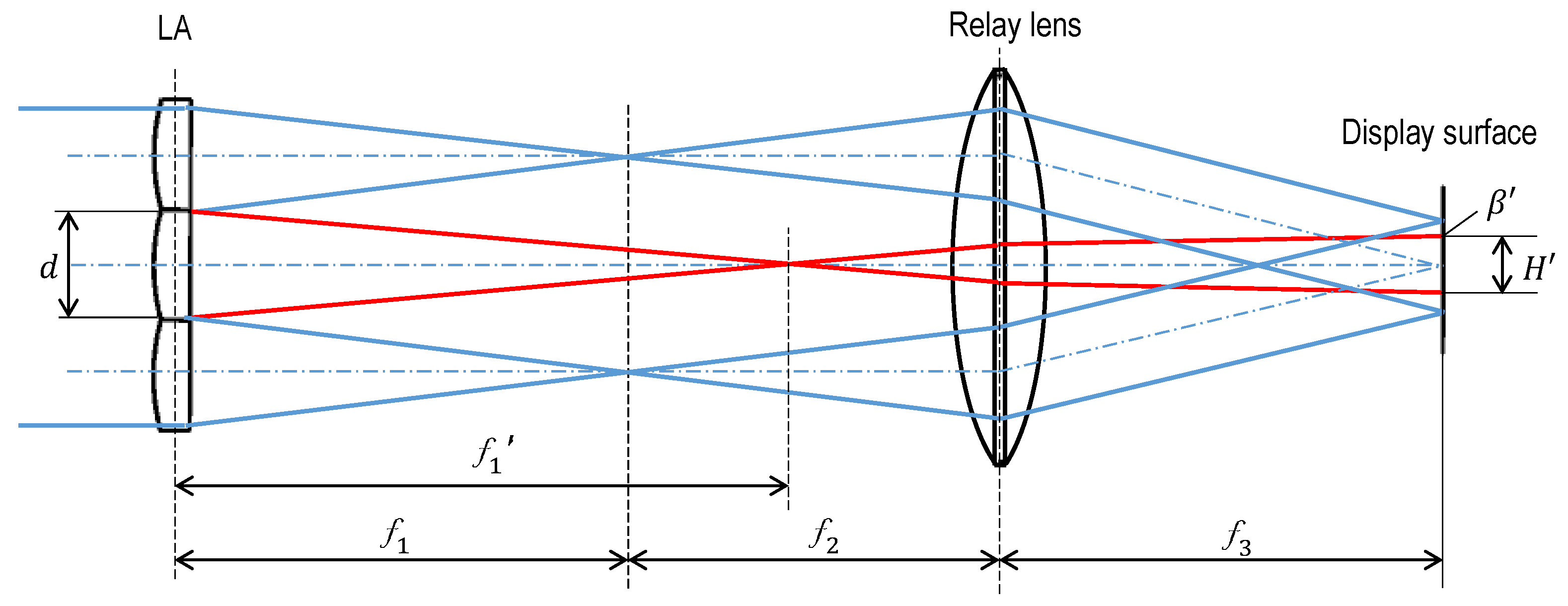
An LA homogenizer requires the same aperture dimension and focal length of all lenslets. By differentiating these identical aspects, inhomogeneous illumination patterns can be generated. One possibility is to lengthen the focal lengths of individual lenslet, so that more centralized illumination areas can be generated [14]. Figure 9 illustrates a simple principle of such an optic. d, , , and have the same meanings as those in Formula (3), denotes the lengthened focal length of the central lenslet, which intends to create the hotspot; denotes the maximum incident angle of the centralized beamlet on the display surface (the red line to the display surface in the figure), which is not important in this discussion; and, denotes the centralized distribution hotspot area resulted from the focal length changing.
The hotspot area dimension in this illustration can be customized according to the ABCD matrix shown in Formula (7):
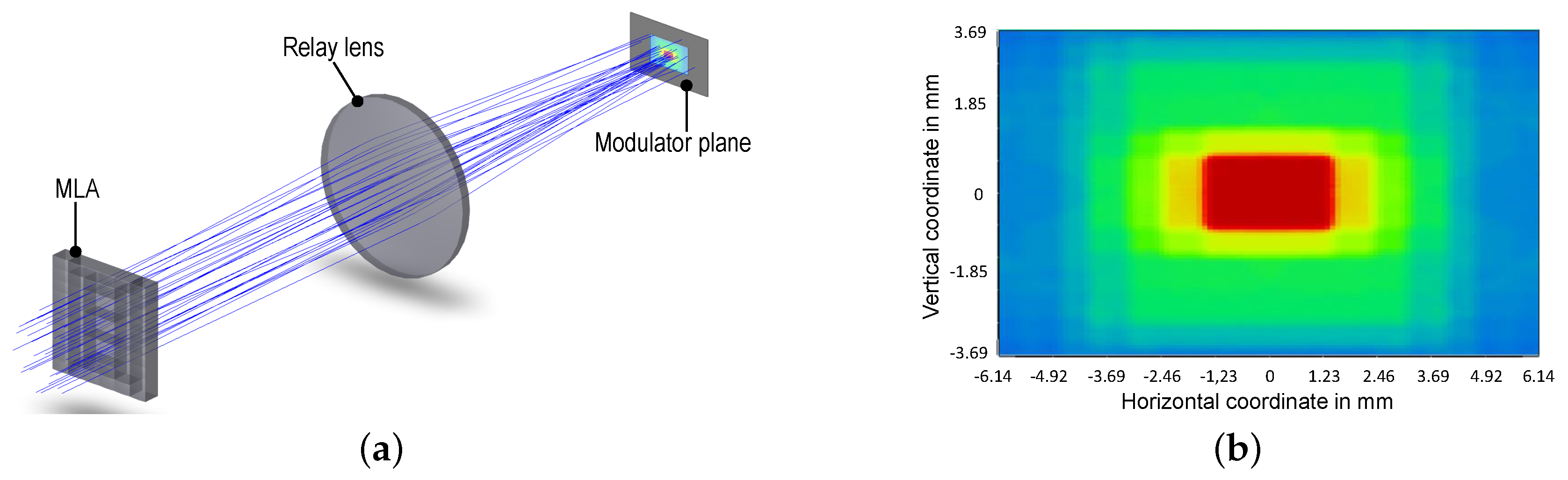
A validation of this hot spot generation method is accomplished by optical simulation. The optical system is modified from the one presented in Section 4. The simulation model with its result is shown in Figure 10 [14]. Both of the optical components in the simulation model are made of PMMA. The system exhibits an optical efficiency of (with uncoated surfaces). The distribution that is shown in Figure 10b is quantified to a real headlamp’s level, and it is compared with the regulation later.
5.2. Modification on Lenslet Dimension
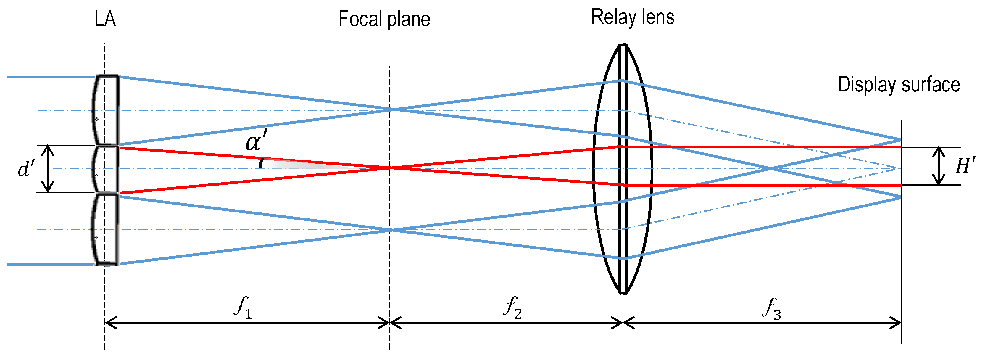
Another method to create the required illumination hotspot besides lengthening the focal length is through the modification on the lenslet dimension. The focal lengths of individual lenslets stay the same. When the dimension of a lenslet decreases, it results in a centralized distribution area, as illustrated in Figure 11.
In this figure, is the modified lenslet aperture dimension, which leads to a smaller image of itself with the size of on the display surface. The inhomogeneous distribution pattern is therefore generated. This smaller lenslet dimension also leads to a smaller incident angle on the virtual focal plane. Thus, the geometry relationships of the modified and the resulted parameters can be confirmed while using Formulas (8) and (9).
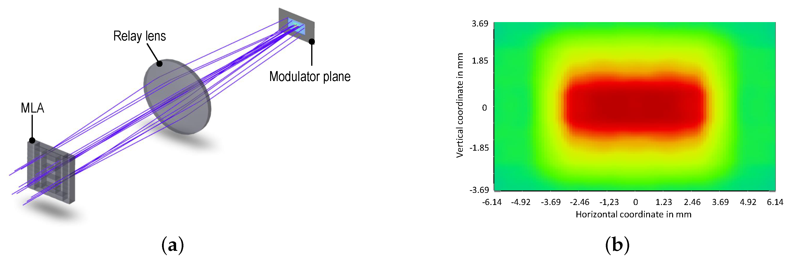
A simulation model modified from that in Section 4 is also used for the validation of this method. The inner lenslets are half the size of the outer lenslets. The simulated system and its result are shown in Figure 12. The optical efficiency, according to the simulation, is with PMMA components.
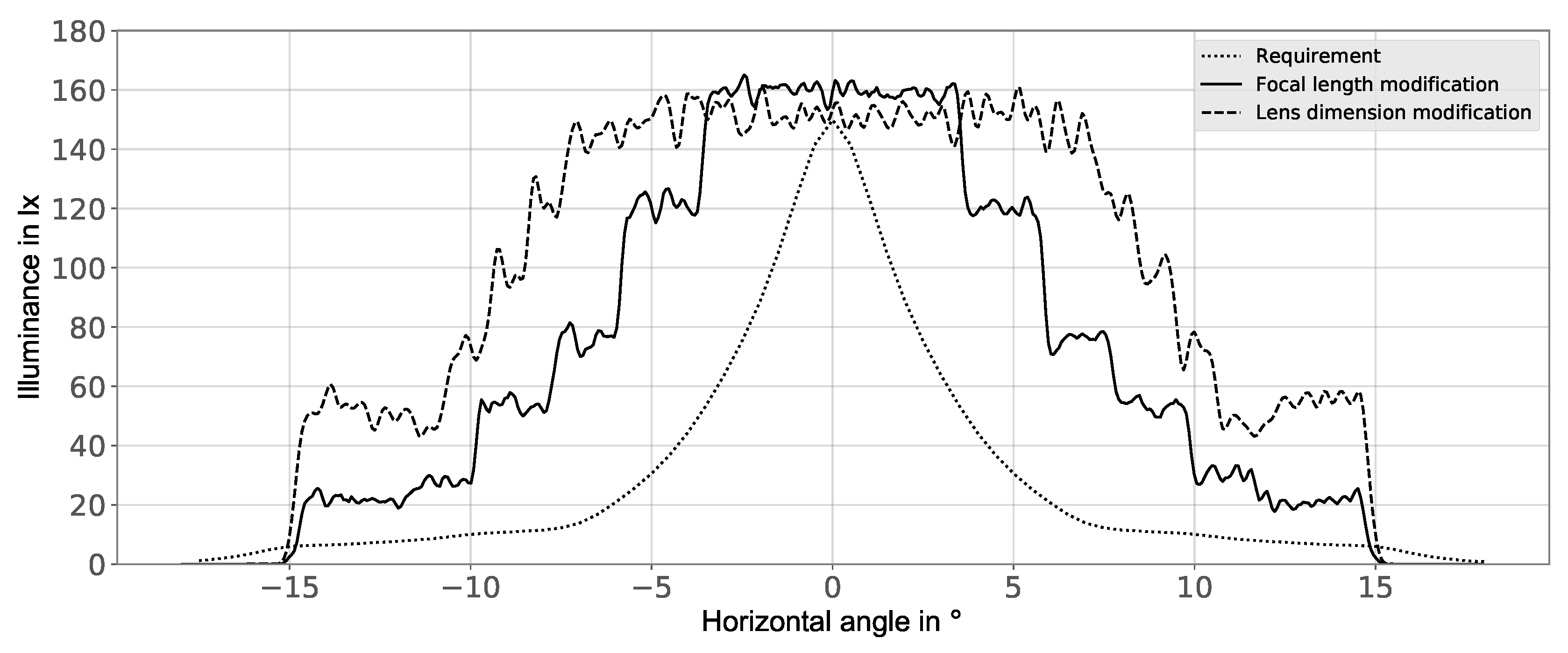
Figure 13 shows acomparison of the simulation results with the high beam requirement. The dotted curve in the figure shows the requirement in terms of the minimum illuminance in a headlamp’s FoV (field of view). The illuminance distribution of a headlamp must not be below this curve in the FoV. Both of the resulted distributions in Section 5.1 and Section 5.2 are further shaped by a projection lens to achieve an FoV of in the horizontal direction and in the vertical direction. The simulation results are quantified to the same level of the regulation, and the comparison result is as illustrated. According to the comparison, the two hotspot generation methods can fulfill the requirements in the regulation for headlamp systems.
Both of the methods described in Section 5.1 and Section 5.2 are on the base of the fundamental principle of the LA homogenizer. By modifying this basic principle, centralized illumination hotspots can be customized. Depending on the specific design requirement of a high-resoultion headlamp, optional methods for homogeneous or inhomogeneous lighting distribution can be correspondingly applied.
A twisted nematic LCoS is selected as an example because of its potentiality in headlamp applications. First, an LCoS has high aperture ratios and reflectances, which are beneficial for the optical efficiency and the thermal management in high power systems, i.e., headlamp systems in the context [30]. Next, the pursuit of efficiency and compaction of a headlamp suggests the appliance of laser diodes as the light source [4]. A laser diode emits linearly polarized light, which fits the working mechanism of the LCoS well. The collaborative work of laser diodes and LCoS modulators can improve energy efficiency and contrast performance in a headlamp. Nevertheless, except for the LCoS, the two proposed methods for the central hot spot generation can be applied for other area-based modulators, e.g., DMDs and LCDs, in high-resolution headlamp systems.
6. Conclusions
This paper introduces methods for the realization of different illumination patterns of area-based high-resolution headlamp systems while using LA optical elements. It explains the motivation of high-resolution headlamps in the first place, followed by the state of the art of lighting distributions of such systems. LAs are introduced as the beam pre-shaping optics in order to achieve different illumination patterns. The first use of LAs is to realize homogeneous lighting distributions for diverse target areas. The basic working principle and design methods of such LA homogenizers are introduced in this paper, with the validation using simulation and measuring results according to ANSI standards. Based on the homogenization working principle, two innovative approaches of using modified LAs as inhomogenizers for high-resolution headlamps are subsequently introduced. Each of the approaches can generate an inhomogeneous illumination pattern with a central hotspot. Thus, the ability and potentiality of LAs for various application scenarios for upcoming vehicle headlamps are comprehensively presented.
Author Contributions
Conceptualization, Y.L. and M.K.; methodology, Y.L.; software, Y.L.; validation, Y.L. and M.K.; formal analysis, Y.L. and M.K.; investigation, Y.L.; resources, Y.L., M.K. and R.L.; writing–original draft preparation, Y.L.; writing–review and editing, M.K. and R.L.; visualization, Y.L. and M.K.; supervision, R.L.; project administration, R.L. All authors have read and agree to the published version of the manuscript.
Funding
This research project was funded by the Ministry of Science and Culture of Lower Saxony within the framework of project Tailored Light.
Conflicts of Interest
The authors declare no conflict of interest.
Abbreviations
The following abbreviations are used in this manuscript:
| ANSI | American national standards institute |
| DMD | Digital micromirror device |
| FoV | Field of View |
| LA | Lenslet array |
| LCD | Liquid crystal display |
| LCoS | Liquid crystal on silicon |
| LED | Light-emitting diode |
| PBS | Polarizing beam splitter |
| PMMA | Polymethyl methacrylate |
References
- Gut, C.; Cristea, I.; Neumann, C. High-resolution headlamp. Adv. Opt. Technol. 2016, 5, 109–116. [Google Scholar] [CrossRef]
- Pfullmann, N.; Thiel, A.; Thamm, M.; Plöger, R.; Kloppenburg, G.; Wolf, A.; Lachmayer, R. From mechanical adb systems to high resolution headlamps-new opportunities of novel headlight systems. In Proceedings of the 12th International Symposium on Automotive Lighting, Darmstadt, Germany, 25–27 September 2017; Khanh, T.Q., Ed.; Herbert Utz Verlag GmbH: München, Germany, 2017; Volume 17, pp. 357–365. [Google Scholar]
- Held, M.P.; Kloppenburg, G.; Lachmayer, R. Micro pixel LEDs: Design challenge and implementation for high-resolution headlamps. In Light-Emitting Devices, Materials, and Applications; International Society for Optics and Photonics: San Francisco, CA, USA, 2019; Volume 10940, p. 109401U. [Google Scholar] [CrossRef]
- Li, Y.; Knöchelmann, M.; Lachmayer, R. High-resolution headlamps: Innovative functionalities and the potential of using laser diodes as light sources. In Proceedings of the 7th International Forum on Automotive Lighting (IFAL), Shanghai, China, 25–26 June 2019. [Google Scholar] [CrossRef]
- Kloppenburg, G.; Wolf, A.; Lachmayer, R. High-resolution vehicle headlamps: Technologies and scanning prototype. Adv. Opt. Technol. 2016, 5, 147–155. [Google Scholar] [CrossRef] [Green Version]
- Knöchelmann, M.; Held, M.P.; Kloppenburg, G.; Lachmayer, R. High-resolution headlamps–technology analysis and system design. Adv. Opt. Technol. 2019, 8, 33–46. [Google Scholar] [CrossRef]
- Knöchelmann, M.; Kloppenburg, G.; Lachmayer, R. Headlamp innovations: Optical concepts for fully adaptive light distributions. In Emerging Digital Micromirror Device Based Systems and Applications X; International Society for Optics and Photonics: San Francisco, CA, USA, 2018; Volume 10546, p. 105460K. [Google Scholar] [CrossRef]
- Willeke, B.; Schüler, F.; Kley, F.; Fischer, G. High Resolution Headlamp–Investigation towards a RGB-Laser LCD Backlight. In Proceedings of the 11th International Symposium on Automotive Lighting, Darmstadt, Germany, 29–30 September 2015; Khanh, T.Q., Ed.; Herbert Utz Verlag GmbH: München, Germany, 2015; pp. 531–536. [Google Scholar]
- Reinert-Weiss, C.J.; Baur, H.; Nusayer, S.A.A.; Duhme, D.; Frühauf, N. Development of active matrix LCD for use in high-resolution adaptive headlights. J. Soc. Inf. Disp. 2017, 25, 90–97. [Google Scholar] [CrossRef]
- Roth, J.; Petermann-Stock, I. High resolution LCoS Headlight. In Optische Technologien in der Fahrzeugtechnik: 8. VDI-Tagung, Karlsruhe, 05. und 06. Juni 2018/VDI/VDE-Gesellschaft Mess- und Automatisierungstechnik, Optische Technologien. VDI-Tagung Optische Technologien in der Fahrzeugtechnik; VDI Wissensforum GmbH: Düsseldorf, Germany, 2018; Volume 2323, pp. 49–59. ISBN 978-3-18-092323-9. [Google Scholar]
- Schmidt, C. Adverse Weather Light: New Chances for a technically unsolved problem. In Proceedings of the 12th International Symposium on Automotive Lightning, Darmstadt, Germany, 25–27 September 2017; Khanh, T.Q., Ed.; Herbert Utz Verlag GmbH: München, Germany, 2017; Volume 17, pp. 201–209. [Google Scholar]
- Grötsch, S.; Hiller, U.; Reill, J.; Huber, R. Benefits of Electronics Integration into LED Components. In Optische Technologien in der Fahrzeugtechnik: 8. VDI-Tagung, Karlsruhe, 05. und 06. Juni 2018/VDI/VDE-Gesellschaft Mess- und Automatisierungstechnik, Optische Technologien. VDI-Tagung Optische Technologien in der Fahrzeugtechnik; VDI Wissensforum GmbH: Düsseldorf, Germany, 2018; Volume 2323, pp. 3–14. ISBN 978-3-18-092323-9. [Google Scholar]
- Gut, C.; Rotscholl, I.; Neumann, C. Theoretische Leistungs- und Effizienzanalyse laserbasierter Pixellichtsysteme. In 6. VDI-Tagung Optische Technologien in der Fahrzeugtechnik // Optische Technologien in der Fahrzeugtechnik; VDI., Ed.; VDI-Verl.: Düsseldorf, Germany, 2014; Volume 2221, pp. 15–29. ISBN 978-3-18-09221-8. [Google Scholar]
- Li, Y.; Knöchelmann, M.; Lachmayer, R. Concepts of inhomogeneous illumination of area-based light modulators for high-resolution headlamps. In Emerging Digital Micromirror Device Based Systems and Applications XI; International Society for Optics and Photonics: San Francisco, CA, USA, 2019; Volume 10932, p. 109320P. [Google Scholar] [CrossRef]
- Günther, A. Optical concept for an active headlamp with a DMD array. In Optical Sensors 2008; International Society for Optics and Photonics: Strasbourg, France, 2008; Volume 7003, p. 70032D. [Google Scholar] [CrossRef]
- Bhakta, V.R.; Ballard, B. High resolution adaptive headlight using Texas Instruments DLP® technology. In Proceedings of the 11th International Symposium on Automotive Lighting, Darmstadt, Germany, 29–30 September 2015; Khanh, T.Q., Ed.; Herbert Utz Verlag GmbH: München, Germany, 2015; pp. 483–494. [Google Scholar]
- Wolf, A.; Kloppenburg, G.; Danov, R.; Lachmayer, R. Dmd based automotive lighting unit. DGaO Proc. 2016. [Google Scholar] [CrossRef]
- Benner, G.; Probst, W. Köhler Illumination in the TEM: Fundamentals and advantages. J. Microsc. 1994, 174, 133–142. [Google Scholar] [CrossRef]
- Arecchi, A.V.; Koshel, R.J.; Messadi, T. Field Guide to Illumination; SPIE: Bellingham, WA, USA, 2007; Volume FG11, ISBN 978-0-8194-6768-3. [Google Scholar]
- Schreiber, P.; Kudaev, S.; Dannberg, P.; Zeitner, U.D. Homogeneous LED-illumination using microlens arrays. In Nonimaging Optics and Efficient Illumination Systems II; International Society for Optics and Photonics: San Diego, CA, USA, 2005; Volume 5942, p. 59420K. [Google Scholar] [CrossRef]
- Lizana, A.; Martín, N.; Estapé, M.; Fernández, E.; Moreno, I.; Márquez, A.; Iemmi, C.; Campos, J.; Yzuel, M. Influence of the incident angle in the performance of liquid crystal on silicon displays. Opt. Express 2009, 17, 8491–8505. [Google Scholar] [CrossRef] [Green Version]
- Texas Instruments. DLP7000 DLP 0.7 XGA 2x LVDS Type A DMD; Texas Instruments: Dallas, TX, USA, 2019. [Google Scholar]
- Chaves, J. Introduction to Nonimaging Optics, 2nd ed.; CRC Press: Boca Raton, FL, USA, 2016; ISBN 978-1482206739. [Google Scholar]
- American National Standards Institute. American National Standard for Audiovisual Systems: Electronic Projection, Variable Resolution Projectors; ANSI: Washington, DC, USA, 1998. [Google Scholar]
- Cheng, C.M.; Chern, J.L. Illuminance formation and color difference of mixed-color light emitting diodes in a rectangular light pipe: An analytical approach. Appl. Opt. 2008, 47, 431–441. [Google Scholar] [CrossRef] [PubMed]
- Yao, P.H.; Chen, C.H.; Chen, C.H. Low speckle laser illuminated projection system with a vibrating diffractive beam shaper. Opt. Express 2012, 20, 16552–16566. [Google Scholar] [CrossRef]
- Mizuyama, Y.; Harrison, N.; Leto, R. Despeckling fly’s eye homogenizer for single mode laser diodes. Opt. Express 2013, 21, 9081–9090. [Google Scholar] [CrossRef] [PubMed]
- Uche, C.; Fracasso, B.; Crossland, W.A.; De Bougrenet de la Tocnaye, J.; Wilkinson, T.D. Development of large capacity and low-crosstalk holographic switches using LCOS spatial light modulators. Ferroelectrics 2002, 278, 219–226. [Google Scholar] [CrossRef]
- Shapiro, L. New ANSI/IEC standard for projectors. In Projection Displays II; International Society for Optics and Photonics: San Jose, CA, USA, 1996; Volume 2650, pp. 209–216. [Google Scholar] [CrossRef]
- Bleha, W.P., Jr.; Lei, L.A. Advances in liquid crystal on silicon (LCOS) spatial light modulator technology. In Display Technologies and Applications for Defense, Security, and Avionics VII; International Society for Optics and Photonics: Baltimore, MD, USA, 2013; Volume 8736, p. 87360A. [Google Scholar] [CrossRef]
- United Nations Economic Commission for Europe. Regulation No. 113 of United Nations Economic Commission for Europe (UNECE)—Headlamps Emitting a Symmetrical Passing-Beam; Publications Office of the European Union: Brussels, Belgium, 2012. [Google Scholar]
Figure 1.
Example of the illumination distribution of a high-resolution headlamp, which includes a general illumination area and a high-resolution area.
Figure 1.
Example of the illumination distribution of a high-resolution headlamp, which includes a general illumination area and a high-resolution area.

Figure 2.
Typical Köhler illumination principle in microscopy systems, it provides a homogeneous illumination pattern for the specimen by imaging the filament.
Figure 2.
Typical Köhler illumination principle in microscopy systems, it provides a homogeneous illumination pattern for the specimen by imaging the filament.

Figure 3.
Working principle illustration of a lenslet array (LA) homogenizer, the LA is composed of three lenslets.
Figure 3.
Working principle illustration of a lenslet array (LA) homogenizer, the LA is composed of three lenslets.

Figure 4.
Expanation how the second LA revise the initial divergent angle from the light source, d, and are the same as in Figure 3.
Figure 4.
Expanation how the second LA revise the initial divergent angle from the light source, d, and are the same as in Figure 3.

Figure 5.
Simulation model of a LA homogenizer with the distibutions of the radiation intensity of the incident light and the target plane.
Figure 5.
Simulation model of a LA homogenizer with the distibutions of the radiation intensity of the incident light and the target plane.

Figure 6.
Demonstrator setup and manufactured LA. (a) Demonstrator schematic for the performance investigation; (b) The manufactured LA.
Figure 6.
Demonstrator setup and manufactured LA. (a) Demonstrator schematic for the performance investigation; (b) The manufactured LA.

Figure 7.
Homogeneity measuring illustration. (a) The 13 measuring points defined by ANSI [24,29]; (b) The measuring setup.

Figure 8.
Projection and measuring results of the investigation setup. (a) The measured luminance image from the LMK Color 5; (b) The real projection photo.
Figure 8.
Projection and measuring results of the investigation setup. (a) The measured luminance image from the LMK Color 5; (b) The real projection photo.

Figure 9.
Principle of a focal length changed LA inhomogenizer [14].
Figure 9.
Principle of a focal length changed LA inhomogenizer [14].

Figure 10.
Simulation model and its result for the hotspot generation based on the modification of focal length. (a) Simulation model; (b) Detector view located at the modulator plane [14].
Figure 10.
Simulation model and its result for the hotspot generation based on the modification of focal length. (a) Simulation model; (b) Detector view located at the modulator plane [14].

Figure 11.
Principle of a aperture size changed LA inhomogenizer.

Figure 12.
Simulation model and its result for the hotspot generation based on the modification of lenslet dimension. (a) Simulation model; (b) Detector view located at the modulator plane.
Figure 12.
Simulation model and its result for the hotspot generation based on the modification of lenslet dimension. (a) Simulation model; (b) Detector view located at the modulator plane.

Figure 13.
A comparison of the quantified distributions with the requirements for headlamp high beams in [31].
Figure 13.
A comparison of the quantified distributions with the requirements for headlamp high beams in [31].


Table 1.
Parameter list of the iquid crystal on silicon (LCoS), which is used as the lighting modulator in the demonstrator.
Table 1.
Parameter list of the iquid crystal on silicon (LCoS), which is used as the lighting modulator in the demonstrator.
| Resolution | Active Area | Aspect Ratio | Aperture Ratio | Reflectance | Waveband |
|---|---|---|---|---|---|
| 12.29 × 7.37 mm | 420–700 nm |
© 2020 by the authors. Licensee MDPI, Basel, Switzerland. This article is an open access article distributed under the terms and conditions of the Creative Commons Attribution (CC BY) license (http://creativecommons.org/licenses/by/4.0/).
Share and Cite
MDPI and ACS Style
Li, Y.; Knöchelmann, M.; Lachmayer, R. Beam Pre-Shaping Methods Using Lenslet Arrays for Area-Based High-Resolution Vehicle Headlamp Systems. Appl. Sci. 2020, 10, 4569. https://doi.org/10.3390/app10134569
AMA Style
Li Y, Knöchelmann M, Lachmayer R. Beam Pre-Shaping Methods Using Lenslet Arrays for Area-Based High-Resolution Vehicle Headlamp Systems. Applied Sciences. 2020; 10(13):4569. https://doi.org/10.3390/app10134569
Chicago/Turabian StyleLi, Yang, Marvin Knöchelmann, and Roland Lachmayer. 2020. "Beam Pre-Shaping Methods Using Lenslet Arrays for Area-Based High-Resolution Vehicle Headlamp Systems" Applied Sciences 10, no. 13: 4569. https://doi.org/10.3390/app10134569
Note that from the first issue of 2016, this journal uses article numbers instead of page numbers. See further details here.