Article

Degradation Monitoring of Insulation Systems Used in Low-Voltage Electromagnetic Coils under Thermal Loading Conditions from a Creep Point of View

1
Key Laboratory of Networked Control Systems, Chinese Academy of Sciences, Shenyang 110016, China
2
Shenyang Institute of Automation, Chinese Academy of Sciences, Shenyang 110016, China
3
Institutes for Robotics and Intelligent Manufacturing, Chinese Academy of Sciences, Shenyang 110169, China
4
University of Chinese Academy of Sciences, Beijing 100049, China
5
Liaoning Institute of Science and Technology, Benxi 117004, China
6
Center for Advanced Life Cycle Engineering, University of Maryland, College Park, MD 20742, USA
*
Author to whom correspondence should be addressed.
Sensors 2020, 20(13), 3696; https://doi.org/10.3390/s20133696
Submission received: 4 June 2020 / Revised: 26 June 2020 / Accepted: 27 June 2020 / Published: 1 July 2020
(This article belongs to the Special Issue Sensors for Fault Diagnosis and Prognostics)

Abstract

:
Electromagnetic coils are a key component in a variety of systems and are widely used in many industries. Because their insulation usually fails suddenly and can have catastrophic effects, degradation monitoring of coil insulation systems plays a vital role in avoiding unexpected machine shutdown. The existing insulation degradation monitoring methods are based on assessing the change of coil high-frequency electrical parameter response, whereas the effects of the insulation failure mechanisms are not considered, which leads to inconsistency between experimental results. Therefore, this paper investigates degradation monitoring of coil insulation systems under thermal loading conditions from a creep point of view. Inter-turn insulation creep deformation is identified as a quantitative index to manifest insulation degradation changes at the micro level. A method is developed to map coil high-frequency electrical monitoring parameters to inter-turn insulation creep deformation in order to bridge the gap between the micro-level and macro-level changes during the incipient insulation degradation process. Thermally accelerated tests are performed to validate the developed method. The mapping method helps to determine the physical meaning of coil electrical monitoring parameters and presents opportunities for predictive maintenance of machines that incorporate electromagnetic coils.

1. Introduction

Electromagnetic coils are fundamental energy conversion and transformation components of many systems [1]. Although they are widely used in motors, transformers, and solenoids, they are failure-prone. Many papers have reported that stator-winding insulation is one of the weakest components in an electric machine [2,3,4,5]. A study conducted by Oak Ridge National Laboratory [6] showed that over 50% of solenoid valve failures in U.S. nuclear power plants were attributed to electromagnetic coil faults (e.g., coil open, coil short). For electric generators, 56% of failures originated as electrical insulation damage [7,8]. Further, insulation failure is one of the dominant failure modes for classical wind turbines [9]. New applications, especially in more-electric aircraft, should widen the use of low-voltage (under 1 kV) electrical rotating machines [10]. However, approximately 40% of the failures in low-voltage rotating machines have originated from the stator-winding insulation materials [11]. The reliability of the low-voltage coil insulation systems in rotating machines has thus become a critical issue and requires technical-conditions-monitoring to avoid unexpected shutdown of machines that incorporate electromagnetic coils.
Testing and monitoring methods for insulation systems of electromagnetic coils have been surveyed in Grubic et al. [12]. The classical methods used to characterize the quality of a winding insulation can be categorized into off-line testing and on-line monitoring methods, which are shown in Figure 1. The off-line testing methods are so far the most industrially accepted [13] and are usually based on visual inspection and electrical, physical, and chemical measurement. For example, Stone [14,15] discussed a few methods that rely on physical contact with and measurement of the insulation (e.g., capacitance, dissipation factor, and insulation resistance) as a dielectric between the wire conductor and an outside ground plane. In this case, electrodes are required to be placed outside the insulation. Considering that electromagnetic coils in solenoid valves or motors are generally encased or otherwise unavailable for intrusive inspection, these methods require the machines under test to stop and to be disassembled, which means that they can only be applied off-line during predefined maintenance periods. Because off-line testing methods thus interrupt the running of the plant, continuous health assessment of the coils through on-line monitoring is preferred to improve the plant safety levels and optimize the maintenance schedule.
The on-line monitoring methods can be further divided into inter-turn short fault detection methods and inter-turn insulation degradation monitoring methods. In order to illustrate the relationship between these two methods clearly, insulation deterioration process is analyzed, as shown in Figure 2. Since insulation breakdown of electromagnetic coils usually originates from a turn-to-turn short [16], the deterioration process is divided into incipient and late degradation phases according to whether or not the turn-to-turn fault has occurred [17]:
Incipient degradation phase: As a current is passed through the wire, Joule heating causes an increase in the wire temperature, which results in expansion of the conductor (usually copper) and thus compressive stress on turn-to-turn insulation (usually a polymer). Under the long-term effects of compressive and thermal stresses on the turn-to-turn insulation, the insulation materials degrade and lead to a turn-to-turn short.
Late degradation phase: After the turn-to-turn short occurs, the direct-current (DC) resistance of the coil decreases, and thus current increases, which makes the coil temperature increase. A hot spot can form at the location of the short. Turn-to-turn short faults will spread quickly around the hot spot, which causes the coil to burn out, finally resulting in failure of the complete coil.
Accordingly, the inter-turn short fault detection methods are used in late degradation phase to detect if the turn-to-turn short forms or to assess fault severity by identifying the number of inter-turn shorts, whereas the inter-turn insulation degradation monitoring methods are used in the incipient degradation phase to monitor the health state of insulation before the turn-to-turn short formation.
(1) Inter-turn short fault detection methods
Motor current signature analysis (MCSA) is commonly used to detect inter-turn short fault by analyzing the stator current spectrum. The basic principle of MCSA is that the frequency domain features of the stator current will change (e.g., 3rd harmonic was observed) in the event of an inter-turn short. The classical MCSA methods include Fourier-transform-based methods [18,19], and wavelet-transform-based methods [20,21].
Other commonly used methods are based on the principle that motor symmetry is changed after the turn-to-turn short formation. The classical methods include the negative-sequence-current-component-based methods [22], Park’s vector approach, and extended Park’s-vector-based methods [23].
Artificial-intelligence-based methods are proposed in order to eliminate the interference of noise during fault detection, in which winding current signals with different health states are acquired to train classifiers. Thus, these methods can be used to classify the different short circuit levels by identifying the number of inter-turn shorts. The most common methods are based on artificial neural network (ANN) [24] and support vector machine (SVM) [25].
Motor magnetic field signals can also be used to detect inter-turn shorts, wherein the motor magnetic field changes in the event of an inter-turn short fault. The classical methods include air-gap-flux-based methods [26,27] by installing search coils inside the motor and leakage-flux-based approaches [28,29] using an external flux sensor outside the motor. Motor magnetic-field-signal-based methods can provide fault location information comparing to the MCSA-based methods.
According to the analysis mentioned above, the application premise of inter-turn short detection methods is that the turn-to-turn short has already formed. However, once the turn-to-turn short forms, the coil insulation degradation process accelerates, and the impending insulation failure usually occurs suddenly and has catastrophic effects. For example, it has been shown that it takes less than 2 s for a single turn fault to develop into a critical fault in a typical 15-kW induction motor [30]. Therefore, inter-turn short fault detection methods have limited significance for predictive maintenance of machines that incorporate coils.
(2) Inter-turn insulation degradation monitoring methods
Considering coil insulation systems usually go through a slow degradation process before a turn-to-turn fault occurs, inter-turn insulation degradation monitoring presents opportunities for continuous technical conditions monitoring and predictive maintenance of machines that incorporate electromagnetic coils. The representative inter-turn insulation degradation monitoring methods include Werynski et al. [31], who performed an accelerated aging test on twisted pairs of magnet wire with polyester-imide insulation and found that the insulation capacitance increased as breakdown voltage decreased. The phase shift between a signal injected into a motorette, which is designed to be a small-scale model of electric motor stator windings, at the coil resonant frequency and the resulting magnetic field were used as the health indicator for the insulation. Perisse et al. [32,33] showed that changes in the turn insulation capacitance of the electromagnetic coil are reflected in the resonant frequency and thus developed a monitoring system able to detect slight variations of high-frequency resonances in the winding of a working machine fed by an industrial inverter. Savin et al. [34,35] also placed twisted pairs of magnet wire with layered polyester-imide/polyester-amide insulation under thermal stress and found that the partial discharge inception voltage decreased, which is an indication of insulation degradation, whereas the turn-to-turn capacitance increased. Thus, they claimed that the capacitance can be used as an aging indicator of the winding insulation. Zoeller et al. [36,37,38] proposed a method for stator insulation defect detection in traction-drive machine windings by evaluating the current response after a voltage step excitation, which is based on the fact that parasitic winding capacitance changes as the insulation degrades. Nussbaumer et al. [13] proposed a method to monitor changes in the insulation health state by evaluating high-frequency machine properties. The insulation state indicator was defined by feature extraction of the high-frequency information. Jameson et al. [1,39] proposed a low-voltage coil insulation health monitoring method based on the impedance spectrum. The Spearman correlation coefficient was used to find frequency regions of interest within the impedance spectrum.
In summary, the existing inter-turn insulation degradation monitoring methods detect degradation of insulation used in low-voltage coils by assessing the change of high-frequency electrical parameters (e.g., impedance, resonant frequency, and capacitance) response, whereas the effects of insulation failure mechanism on these electrical parameters were not considered. This brings inconsistency between the experimental results of existing studies. Some representative examples are as follows.
(1)
There are contradictory claims for the evolving trends of high-frequency electrical parameters in the literature. For example, Perisse et al. [32] and Savin et al. [34] claimed that the capacitance increased over the aging period while Younsi et al. [40] and Zhang et al. [41] found that the capacitance decreased during the aging time.
(2)
Perisse et al. [33] set a failure threshold of 95% of the healthy coil resonant frequency and mentioned that once the failure threshold is crossed, the coil should be maintained under monitoring. However, the experimental results in Jameson et al. [42] showed that the resonant frequency changed by only 2.5% before a short formed.
The difference between the results from experiments in the previous studies may be due to differences in material properties and failure mechanisms. It is premature to make a conclusion on electrical parameter evolving trends or setting failure thresholds without considering insulation failure mechanisms. It is thus important to illustrate the insulation degradation mechanism, examine related material-level changes under certain loading conditions, and associate those changes with evolving electrical parameters when performing on-line degradation monitoring in situ. Therefore, this paper has developed a creep degradation mechanism for inter-turn insulation, aiming at thermal loading conditions that have been shown to be the primary reason for insulation failure [43]. The framework for insulation degradation monitoring from a creep point of view is shown in Figure 3. On the one hand, creep deformation of inter-turn insulation is the manifestation of insulation degradation on the micro level and can be used to assess the insulation’s health state. However, creep deformation is not easy to measure in-site. On the other hand, coil high-frequency electrical parameters are the manifestation of insulation degradation on the macro level and can be measured in-site. Therefore, a mapping method from coil high-frequency electrical parameters to inter-turn insulation creep deformation is developed, which associates changes at the micro level and macro level during insulation degradation.
The remainder of this paper is organized as follows. Section 2 analyzes the creep degradation mechanism of inter-turn insulation systems and its effects on coil high-frequency electrical parameter response. Section 3 presents a mapping method from the coil electrical parameters to inter-turn insulation creep deformation. Section 4 presents the experimental setup and results. Section 5 concludes the paper.

2. Coil Creep Degradation Mechanism Analysis

2.1. Creep Degradation of Inter-Turn Insulation Systems under Thermal Loading Conditions

A cross-sectional view of an electromagnetic coil is shown in Figure 4. The magnet wire is constructed of conductor coated with insulation material. Excessive thermal stress is the primary cause that leads to insulation breakdown, especially for machines with safety-critical applications. For example, a solenoid valve (SOV) used in safety instrumented systems is maintained in an energized state throughout most of its installed life due to the adoption of the safety philosophy of returning to a fail-safe condition on the loss of air or electrical power. The consequence of the continuously energized SOVs is a more rapid degradation of the turn-to-turn insulation layers, which are usually composed of polymers, because of the long periods of thermal and compressive stresses resulting from Joule heating. These thermal and compressive stresses placed on the insulation create the necessary conditions for the occurrence of inter-turn insulation creep.
Figure 5 shows the idealized polymer curve for creep when both temperature and stress are constant [44]. The initial strain is roughly predicted by its stress-strain modulus. The material will continue to deform slowly with time indefinitely or until rupture or yielding causes failure. The primary region of the curve is the early stage of loading when the creep rate decreases rapidly with time. Then the creep rate reaches a steady state, which is called the secondary creep stage and is followed by a rapid increase (tertiary stage) and fracture [45].
According to the creep degradation mechanism analysis mentioned above, as shown in Figure 5, the inter-turn insulation layer continues to get thinner during the incipient insulation degradation phase. Finally, insulation fracture occurs, which leads to a turn-to-turn short, and the insulation deterioration process enters the late degradation phase. Thus, creep deformation of inter-turn insulation, which is a manifestation of insulation monitoring on the micro-level, provides a novel way for quantifying the insulation degradation status of coils in the incipient insulation degradation phase. Therefore, the insulation health indicator (IHI) can be defined from the creep degradation point of view. The related definitions are as follows.
(1) Insulation layer thickness (ILT):
I L T = ( D 0 D c ) / 2
where D 0 is the outer radius and D c is the inner radius of the wire.
(2) Inter-turn insulation creep deformation (CD):
The creep deformation of inter-turn insulation is defined as the change of the inter-turn insulation layer thickness, which can be calculated as follows:
C D = I L T healthy I L T degraded
where I L T healthy is the insulation layer thickness of the healthy coil and I L T degraded is the insulation layer thickness of the degraded coil.
(3) Insulation health indicator (IHI):
I H I = I L T degraded I L T healthy 100 %
where 0 I H I 1 .

2.2. Coil Electrical Behavior Analysis from a Creep Point of View

Coil electrical behavior is analyzed from a creep point of view in order to analyze the effect of inter-turn insulation creep degradation on coil high-frequency electrical parameter response. Equivalent circuit models (ECMs) can be used to analyze the electrical behavior of the electromagnetic coils. The ECM of the coil can be modeled as a resistance, R, and an inductance, L, in series, then parallel connected with a lumped capacitance, C. Since R and L are assumed to be constant during the coil incipient degradation phase, the evolution of C as the insulation degrades will be discussed in detail.
The parasitic capacitance network model, as shown in Figure 6, can be used to calculate the total parasitic capacitance of the coil, C, where C t t represents the turn-to-turn capacitance and C t c represents the capacitance between the iron core and innermost layer turn of the coil.
The turn-to-turn capacitance C t t can be calculated according to Equations (4) and (5) [46]:
C t t = ε 0 l t [ ε r θ * l n D 0 D c + cot ( θ * 2 ) cot ( π 12 ) ]
where
θ * = arccos ( 1 l n D 0 D c ϵ r )
where D 0 is the outer diameter of the magnetic wire including the insulation; D c is the inner diameter of the magnetic wire without the insulation (as shown in Figure 4); l t is the turn length; ε r is the relative permittivity of the insulation material; and ε 0 is the vacuum permittivity.
The capacitance between the iron core and innermost layer turn of the coil can be calculated according to Equation (6):
C t c = 2 C t t
Multisim, a circuit simulation software, was used to find the relationship between C and C t t in [47], and the result is as follows:
C = k C t t
where k is an empirical constant that is dependent on the number of layers of the coil.
According to theoretical derivation mentioned above, the effect of inter-turn creep deformation on coil high-frequency parameters response, such as coil parasitic capacitance C, can be analyzed, as shown in Figure 7. As the insulation degrades, inter-turn insulation creep deformation occurs on the micro-level. Then the inter-turn insulation creep deformation makes D 0 / D C change, which leads to turn-to-turn capacitance C t t change. Finally, the coil high-frequency electrical parameter consequently changes as the C t t changes. Therefore, turn-to-turn capacitance C t t is the link between the micro-level and macro-level changes during the incipient insulation degradation process.

3. A Mapping Method from Coil Electrical Parameters to Inter-Turn Insulation Creep Deformation

Coil high-frequency electrical parameters can be used as on-line monitoring parameters during the incipient degradation phase because they are a manifestation of insulation degradation on the macro-level and are easy to measure in situ. A method is developed in this section to map coil high-frequency electrical parameters to inter-turn insulation creep deformation, which helps to determine the physical meaning of on-line monitoring parameters and thus presents opportunities to promote the accuracy of remaining useful life prediction of electromagnetic coil insulation.
Resonant frequency is a commonly used parameter for coil health monitoring, and this section discusses the mapping method using coil resonant frequency as an example. Considering that C t t is the link between micro-level and macro-level variation during the insulation degradation process, a framework for mapping from coil resonant frequency to inter-turn insulation creep deformation is developed, which can be divided into the following 2 steps, as shown in Figure 8.
(1) Step 1: Mapping from coil resonant frequency to turn-to-turn capacitance
The resonant frequency, f r , is defined as the frequency at which reactance is zero, and it can be obtained by splitting the impedance into its real (resistance) and imaginary (reactance) parts, then setting reactance equal to zero and solving for frequency. f r can be expressed as:
f r = 1 2 π L C
where L is the coil inductance and C is the coil capacitance.
Then,
C = 1 / ( 4 π 2 L f r 2 k )
According to Equation (7),
C t t = 1 / ( 4 π 2 L f r 2 k )
So, according to Equation (10), turn-to-turn capacitance C t t can be calculated by measuring the coil resonant frequency.
(2) Step 2: Mapping from turn-to-turn capacitance to inter-turn insulation creep deformation
Assume D c is constant during the incipient degradation phase, thus inter-turn insulation creep deformation can be obtained by calculating D 0 under the healthy and degraded cases, respectively. According to Equations (4) and (5), D 0 can be calculated by the following optimization method.
The optimization function:
f = C t t ε 0 l t [ ε r θ * ln D 0 D c + cot ( θ * 2 ) cot ( π 12 ) ]
where the optimization target is min |f|, and the constraint condition is D C < D 0 < D 0 h e a l t h .
Since L , D c , l t , ε r , and ε 0 can be obtained by measurement, D 0 can be calculated by the optimization process. Since it is a single variable minimization problem, optimization can be performed by a commercial solver tool. Then the inter-turn insulation creep deformation and the insulation health indicator can be calculated according to Equations (1) to (3).
Therefore, coil resonant frequency is mapped to the inter-turn insulation creep deformation by the two-step mapping.

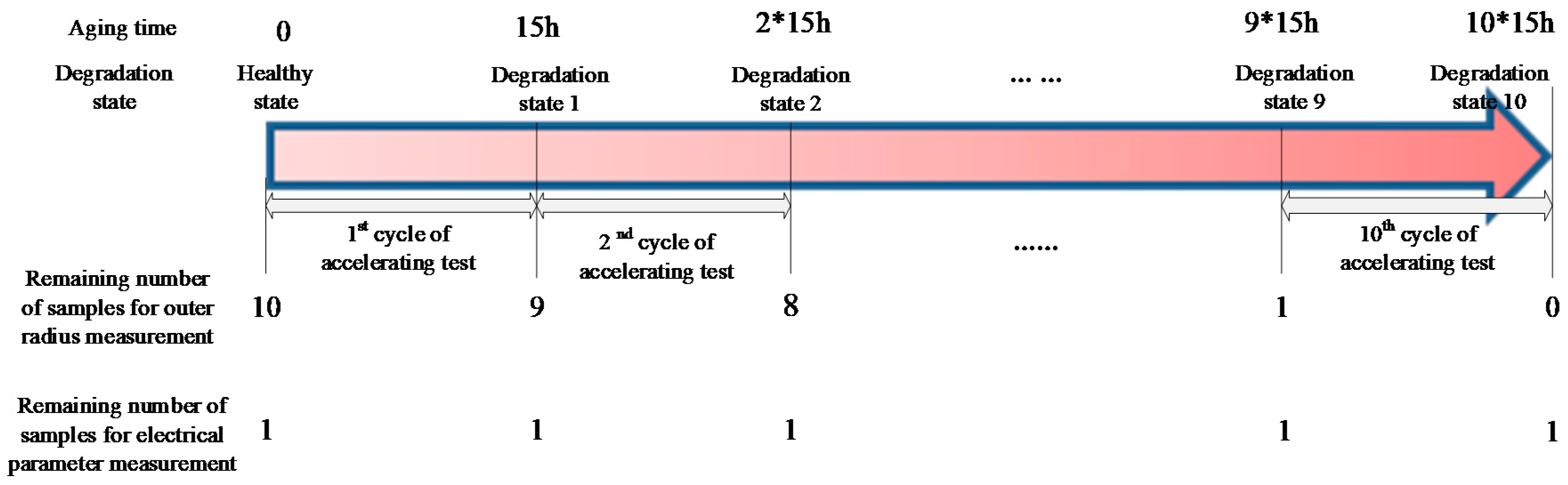
4. Experimental Setup and Results

The purpose of the experiment was to validate the developed creep degradation mechanism and mapping method. The electromagnetic coil was hand-wound using the magnet wire, whose information is shown in Table 1. The coil was put into the chamber and removed periodically from the chamber every 15 h for measurement. As shown in Figure 9, both the coil electrical parameter and the outer radius of a magnet wire were measured after each accelerating cycle. First, a trend analysis of the magnet wire outer radius measurement results was used to validate the developed creep degradation mechanism. Second, the inter-turn insulation creep deformation by calculation based on coil electrical parameter and by actual measurement based on outer radius measurement results was compared to validate the developed mapping method.
The experimental process is described in Figure 10. Ten cycles, namely, 150 h, of the thermally accelerated test were completed in total. Since the coil has to be unraveled in order to measure the outer radius of the magnet wire, the outer radius measurement was performed by destructive examination. Therefore, 10 coil samples were used for this type of measurement. After each accelerated test cycle, one coil was unraveled, and the outer radius of the magnet wire was measured. Then the sample was discarded. One additional sample was used for electrical parameter measurement. Further, the experimental process mentioned above was performed under the accelerated aging temperatures of 210 °C, 220 °C, and 230 °C, respectively. Therefore, (10 + 1) × 3 = 33 samples in total were used in this experiment.

4.1. Outer Radius Measurement of the Magnet Wires

The platform for outer radius measurement is shown in Figure 11. A micrometer was used to measure the outer radius of the magnet wire. The resolution ratio of the micrometer was 0.001 mm. The contact force between the micrometer screw and the sample under test was calibrated by measuring a healthy magnet wire. When the contact force was adjusted to 2 N, the measured value was 0.576 × 10⁻³ m, which is equal to the value by magnet wire specification as described in Table 1. Therefore, the contact force was fixed to 2 N in the following measurement during the experiment. Considering that the diameter of the wire may differ along the wire, as for each outer radius measurement after a certain accelerating cycle, the measurement is performed at 5 different positions along the length of wire in order to reduce the measurement uncertainties. Then the 5 measurement results are averaged, and the mean value is used as the final measurement value. The outer radius measurement results are shown in Figure 12. Further, according to Equation (2), the inter-turn insulation creep deformation can be calculated, and it has negative correlation to the outer radius of the wire. The inter-turn insulation creep deformations during the experiment are shown in Figure 13.

4.2. Coil Electrical Parameter Measurement

The coil electrical parameter measurement platform is shown in Figure 14. The terminals of the coil under test were connected to a Keysight E4980A LCR meter, and a 500-mV signal was applied across the coil. The impedance data collection by the LCR meter was controlled externally by LabVIEW and started only when the coil had cooled to room temperature. The reactance measurement results are shown in Figure 15. In addition, DC resistance (DCR) measurement was done at the same time to ensure the coil was in the incipient degradation phase during the experiment. The DCR measurement result is shown in Figure 16. Further, the DCR threshold for turn-to-turn short D C R threshold is defined as:
D C R threshold = D C R healthy D C R singleturn
where D C R health is 5.41 Ω according to Table 1, D C R sin gleturn refers to DCR of a single turn, and its measurement result is 0.0123 Ω.
Thus, the calculated result for D C R threshold is 5.3977 Ω. As shown in Figure 16, all 10 DCRs measured were greater than D C R threshold , which means that the coils under test were all in the incipient degradation phase during the 10 accelerated cycles. Finally, the relationship between resonant frequency and aging time under these three temperatures can be obtained, as shown in Figure 17.
Next, coil resonant frequency is mapped to inter-turn insulation creep deformation by the mapping method developed in Section 3. The hand-wound coil parameters of l t , ε r , ε 0 , D c , L are shown in Table 1. D 0 can be calculated according to optimization function Equation (11), which is implemented by a commercial solver tool. Inter-turn insulation thickness and creep deformation can consequently be calculated according to Equations (1) and (2). Thus, the curve fitting of the relationship between inter-turn insulation thickness and aging time, and the relationship between inter-turn insulation creep deformation and aging time, are shown in Figure 18 and Figure 19, respectively.

4.3. Experimental Result Analysis

First, according to the magnet wire outer radius measurement results, as shown in Figure 12 and Figure 13, the inter-turn insulation thickness showed a decreasing trend while the inter-turn insulation creep deformation had an increasing trend in general during the experiment. However, the data do not show a monotonous decreasing or increasing trend. The reason for this is that there are differences in temperature at different positions inside the chamber. For example, there is a higher temperature near the heater, whereas there is a lower temperature near the air vent of the chamber. As mentioned earlier, 10 samples were placed in the chamber for magnet wire outer radius measurement under each specified accelerated aging temperature at the beginning of the test. The temperature difference at the different locations inside the chamber leads to the appearance of outlier data points during the experiment, such as the data point at the 6th cycle under 210 °C and the data point at the 8th cycle under 230 °C. Further, as the accelerated aging temperature increased, the creep rate increased. These trends validate the developed creep degradation mechanism.
Second, the measured and calculated results of inter-turn insulation creep deformation, as shown in Figure 13 and Figure 19, respectively, are merged to Figure 20 for comparison. Further, the absolute and relative errors between calculated and measured results are shown in Figure 21. It can be seen from Figure 20 that the calculated creep deformation exceeds the measured creep deformation in general under each accelerating temperature. The reason for this is that the sample used for electrical parameter measurement is placed near the heater of the chamber, which makes the accelerating temperature for the sample used for electrical parameter measurement higher than the samples used for the magnet wire outer radius measurement. Further, as shown in Figure 21, the comparison results show that the errors between calculated and measured inter-turn insulation results are acceptable, which validates the developed mapping method.
Finally, coil resonant frequency is used to calculate inter-turn insulation creep deformation and IHI by the developed mapping method. As shown in Figure 17, coil resonant frequency showed a decreasing trend during the experiment. However, the relationship between resonant frequency and coil health status is still not clear. Therefore, according to the proposed mapping method and Equations (1)–(3), the correlation between coil resonant frequency and IHI under different aging temperatures can be explored, as shown in Figure 22a–c. The relationship between IHI and aging time can thus be obtained, as shown in Figure 23. Since coil resonant frequency can be measured in situ, this makes sense for improving the performance of insulation degradation monitoring based on coil high-frequency electrical parameters. For example, the failure threshold of coil resonant frequency can be set according to its corresponding IHI.

5. Conclusions

Electromagnetic coils are widely used components in many applications and systems, including solenoids, motors, and transformers. However, coil insulation systems are failure-prone, especially under excessive thermal stresses. Further, the coil insulation degradation process accelerates once a turn-to-turn short has occurred, and the impending insulation failure usually occurs suddenly and has catastrophic effects. Thus, insulation degradation monitoring prior to the formation of turn-to-turn shorts presents opportunities for decreasing the safety risk and economic loss due to the unexpected shutdown of machines that incorporate electromagnetic coils.
This paper investigated degradation monitoring of coil insulation systems under thermal loading conditions, which is the primary factor that leads to insulation breakdown, from a creep point of view. Polymer creep curves obtained by inter-turn insulation degradation mechanism analysis and outer radius measurement results of magnet wires during accelerated tests show that the insulation degradation process can be quantified by inter-turn insulation creep deformation on a micro-level. Thus, the insulation health indicator was defined based on insulation layer thickness.
A method of mapping coil high-frequency electrical parameters to inter-turn insulation creep deformation was explored by circuit theories and optimization methods, which is validated by comparison between mapped and measured creep deformation during the thermally accelerated tests. The developed method bridges the gap between the micro-level and macro-level changes during the incipient insulation degradation process, and a knowledge base for insulation degradation monitoring can thus be established by converting the electrical monitoring parameter to coil insulation health status. The developed mapping method helps to reveal the practical physical meaning of coil high-frequency electrical parameters and enhance the prognostic ability of existing high-frequency electrical parameter-based insulation degradation monitoring methods.

Author Contributions

K.W. conceived the approach and wrote the paper; H.G. and A.X. performed the experiments and data analysis; M.P. designed the experiment; all authors read and approved the final manuscript. All authors have read and agreed to the published version of the manuscript.

Funding

The research is supported by the National Key R&D Program of China (2017YFE0123000).

Conflicts of Interest

The authors declare no conflict of interest.

References

  1. Jameson, N.J.; Azarian, M.H.; Pecht, M. Impedance-based Condition Monitoring for Insulation Systems used in Low-voltage Electromagnetic Coils. IEEE Trans. Ind. Electron. 2017, 64, 3748–3757. [Google Scholar] [CrossRef]
  2. 2. Motor Reliability Working Group. Report of Large Motor Reliability Survey of Industrial and Commercial Installations, Part I. IEEE Trans. Ind. Appl. 1985, IA-21, 853–864. [CrossRef]
  3. 3. Motor Reliability Working Group. Report of Large Motor Reliability Survey of Industrial and Commercial Installations, Part II. IEEE Trans. Ind. Appl. 1985, IA-21, 865–872. [CrossRef]
  4. Thorsen, O.V.; Dalva, M. A Survey of Faults on Induction Motors in Offshore Oil Industry, Petrochemical Industry, Gas Terminals, and Oil Refineries. IEEE Trans. Ind. Appl. 1995, 31, 1186–1196. [Google Scholar] [CrossRef]
  5. Albrecht, P.F.; Appiarius, J.C.; McCoy, R.M.; Owen, E.L.; Sharma, D.K. Assessment of the reliability of motors in utility applications—Updated. IEEE Trans. Energy Convers. 1986, EC-1, 39–46. [Google Scholar] [CrossRef]
  6. Bacanskas, V.; Roberts, G.; Toman, G. Aging and Service Wear of Solenoid-Operated Valves Used in Safety Systems of Nuclear Power Plants: Volume 1, Operating Experience and Failure Identification; Technical Report; Franklin Research Center: Philadelphia, PA, USA; Oak Ridge National Lab.: Oak Ridge, TN, USA; Nuclear Regulatory Commission: Washington, DC, USA, 1987. [Google Scholar]
  7. Sant’Ana, W.C.; Salomon, C.P.; Lambert-Torres, G.; da Silva, L.E.B.; Bonaldi, E.L.; de Oliveira, L.E.L.; da Silva, J.G.B. Early Detection of Insulation Failures on Electric Generators through Online Frequency Response Analysis. Electr. Power Syst. Res. 2016, 140, 337–343. [Google Scholar] [CrossRef]
  8. Survey of Hydrogenerator Failures. Available online: https://e-cigre.org/publication/392-survey-of-hydrogenerator-failures (accessed on 26 June 2020).
  9. Arabian-Hoseynabadi, H.; Oraee, H.; Tavner, P.J. Failure Modes and Effects Analysis (FMEA) for Wind Turbines. Int. J. Electr. Power Energy Syst. 2010, 32, 817–824. [Google Scholar] [CrossRef] [Green Version]
  10. Salameh, F.; Picot, A.; Chabert, M.; Maussion, P. Regression Methods for Improved Lifespan Modeling of Low Voltage Machine Insulation. Math. Comput. Simul. 2017, 113, 200–216. [Google Scholar] [CrossRef] [Green Version]
  11. Tavner, P.J. Review of Condition Monitoring of Rotating Electrical Machines. IET Elect. Power Appl. 2008, 2, 215–247. [Google Scholar] [CrossRef]
  12. Grubic, S.; Aller, J.M.; Lu, B.; Habetler, T.G. A Survey on Testing and Monitoring Methods for Stator Insulation Systems of Low-Voltage Induction Machines Focusing on Turn Insulation Problems. IEEE Trans. Ind. Electron. Dec. 2008, 55, 4127–4136. [Google Scholar] [CrossRef] [Green Version]
  13. Nussbaumer, P.; Vogelsberger, M.A.; Wolbank, T.M. Induction Machine Insulation Health State Monitoring Based on Online Switching Transient Exploitation. IEEE Trans. Ind. Electron. 2015, 62, 1835–1845. [Google Scholar] [CrossRef]
  14. Stone, G.C. Condition Monitoring and Diagnostics of Motor and Stator Windings—A Review. IEEE Trans. Dielectr. Electr. Insul. 2013, 20, 2073–2080. [Google Scholar] [CrossRef]
  15. Stone, G.C. Recent important changes in IEEE Motor and Generator Winding Insulation Diagnostic Testing Standards. IEEE Trans. Ind. Appl. 2005, 41, 91–100. [Google Scholar] [CrossRef]
  16. Gyftakis, K.N.; Cardoso, A.J. Reliable Detection of Stator Inter-Turn Faults of Very Low Severity Level in Induction Motors. IEEE Trans. Ind. Electron. 2020. [Google Scholar] [CrossRef]
  17. Wang, K.; Guo, H.; Xu, A.; Jameson, N.J.; Pecht, M.; Yan, B. Creating Self-Aware Low-Voltage Electromagnetic Coils for Incipient Insulation Degradation Monitoring for Smart Manufacturing. IEEE Access 2018, 6, 69860–69868. [Google Scholar] [CrossRef]
  18. Radecki, A.; Dębowski, A.; Wójcik, M.; Lipnicki, P. Evaluation of a Diagnostic Information on Common Electrical Faults Contained in Signals of an Inverter-fed AC IM Drive with Current-oriented Control. In Proceedings of the 2016 10th International Conference on Compatibility, Power Electronics and Power Engineering, Bydgoszcz, Poland, 29 June–1 July 2016; pp. 286–291. [Google Scholar]
  19. Faiz, J.; Nejadi-Koti, H.; Valipour, Z. Comprehensive Review on Inter-turn Fault Indexes in Permanent Magnet Motors. IET Electr. Power Appl. 2017, 11, 142–156. [Google Scholar] [CrossRef]
  20. Malekpour, M.; Phung, B.T.; Ambikairajah, E. Online Technique for Insulation Assessment of Induction Motor Stator Windings under Different Load Conditions. IEEE Trans. Dielectr. Electr. Insul. 2017, 24, 349–358. [Google Scholar] [CrossRef]
  21. Devi, N.R.; Sarma, D.S.; Rao, P.R. Diagnosis and Classification of Stator Winding Insulation Faults on a Three-phase Induction Motor Using Wavelet and MNN. IEEE Trans. Dielectr. Electr. Insul. 2016, 23, 2543–2555. [Google Scholar] [CrossRef]
  22. Lee, S.B.; Tallam, R.M.; Habetler, T.G. A Robust, On-line Turn-fault Detection Technique for Induction Machines Based on Monitoring the Sequence Component Impedance Matrix. IEEE Trans. Power Electron. 2003, 18, 865–872. [Google Scholar]
  23. Cruz, S.M.A.; Cardoso, A.J.M. Stator Winding Fault Diagnosis in Three-phase Synchronous and Asynchronous Motors, by the Extended Park’s Vector Approach. IEEE Trans. Ind. Appl. 2001, 37, 1227–1233. [Google Scholar] [CrossRef]
  24. Bazan, G.H.; Scalassara, P.R.; Endo, W.; Goedtel, A.; Godoy, W.F.; Palácios, R.H. Stator Fault Analysis of Three-phase Induction Motors Using Information Measures and Artificial Neural Networks. Electr. Power Syst. Res. 2017, 143, 347–356. [Google Scholar] [CrossRef]
  25. Yagami, Y.; Araki, C.; Mizuno, Y.; Nakamura, H. Turn-to-Turn Insulation Failure Diagnosis of Stator Winding of Low Voltage Induction Motor with the Aid of Support Vector Machine. IEEE Trans. Dielectr. Electr. Insul. 2015, 22, 3099–3106. [Google Scholar] [CrossRef]
  26. Sun, Y.; Yu, X.; Wei, K.; Huang, Z.; Wang, X. A New Type of Search Coil for Detecting Inter-turn Faults in Synchronous Machines. Proc. Chin. Soc. Electr. Eng. 2014, 34, 917–924. [Google Scholar]
  27. Surya, G.N.; Khan, Z.J.; Ballal, M.S.; Suryawanshi, H.M. A Simplified Frequency-domain Detection of Stator Turn Fault in Squirrel-cage Induction Motors Using an Observer Coil Technique. IEEE Trans. Ind. Electron. 2017, 64, 1495–1506. [Google Scholar] [CrossRef]
  28. Ghanbari, T.; Farjah, A. A Magnetic Leakage Flux-based Approach for Fault Diagnosis in Electrical Machines. IEEE Sens. J. 2014, 14, 2981–2988. [Google Scholar] [CrossRef]
  29. Henao, H.; Demian, C.; Capolino, G.-A. A Frequency-domain Detection of Stator Winding Faults in Induction Machines Using an External Flux Sensor. IEEE Trans. Ind. Appl. 2003, 39, 1272–1279. [Google Scholar] [CrossRef]
  30. Gerada, C.; Bradley, K.; Sumner, M.; Wheeler, P.; Pickering, S.; Clare, J.; Whitley, C.; Towers, G. The Results Do Mesh. IEEE Ind. Appl. Mag. 2007, 13, 62–72. [Google Scholar] [CrossRef]
  31. Werynski, P.; Roger, D.; Corton, R.; Brudny, J.F. Proposition of a New Method for in Service Monitoring of the Aging of Stator Winding Insulation in AC Motors. IEEE Trans. Energy Convers. 2006, 21, 673–681. [Google Scholar] [CrossRef]
  32. Perisse, F.; Werynski, P.; Roger, D. A New Method for AC Machine Turn Insulation Diagnostic Based on High Frequency Resonances. IEEE Trans. Dielectr. Electr. Insul. 2007, 14, 1308–1315. [Google Scholar] [CrossRef]
  33. Perisse, F.; Mercier, D.; Lefevre, E.; Roger, D. Robust Diagnostics of Stator Insulation Based on High Frequency Resonances Measurements. IEEE Trans. Dielectr. Electr. Insul. 2009, 16, 1496–1502. [Google Scholar] [CrossRef]
  34. Savin, S.; Ait-Amar, S.; Roger, D. Turn-to-turn Capacitance Variations Correlated to PDIV for AC Motors Monitoring. IEEE Trans. Dielectr. Electr. Insul. 2013, 20, 34–41. [Google Scholar] [CrossRef]
  35. Savin, S.; Ait-Amar, S.; Roger, D.; Velu, G. Aging Effects on the AC Motor Windings: A Correlation between the Variation of Turn-to-turn Capacitance and the PDIV. In Proceedings of the Annual Report Conference on Electrical Insulation and Dielectric Phenomena (CEIDP), Cancun, Mexico, 16–19 October 2011; pp. 64–67. [Google Scholar]
  36. Zoeller, C.; Vogelsberger, M.A.; Fasching, R.; Grubelnik, W.; Wolbank, T.M. Evaluation and Current-Response Based Identification of Insulation Degradation for High Utilized Electrical Machines in Railway Application. IEEE Trans. Ind. Appl. 2017, 53, 2679–2689. [Google Scholar] [CrossRef]
  37. Zoeller, C.; Vogelsberger, M.; Bazant, M.; Ertl, H.; Wolbank, T.M. Diagnostic Technique for Traction Motor Insulation Condition Monitoring by Transient Signal Assessment. In Proceedings of the PCIM Europe 2018, Nuremberg, Germany, 5–7 June 2018; pp. 1170–1177. [Google Scholar]
  38. Zoeller, C.; Wolbank, T.M.; Vogelsberger, M.A. Influence of Voltage Excitation and Current Sensors on Monitoring of Stator Winding Insulation Based on Transient Current Step Response. In Proceedings of the Energy Conversion Congress and Exposition (ECCE), Montreal, QC, Canada, 20–24 September 2015; pp. 2854–2861. [Google Scholar]
  39. Jameson, N.J.; Azarian, M.H.; Pecht, M. Correlation Analysis for Impedance-based Health Monitoring of Electromagnetic Coils. In Proceedings of the IEEE International Conference on Prognostics and Health Management, Ottawa, ON, Canada, 20–22 June 2016; pp. 1–6. [Google Scholar]
  40. Younsi, K.; Neti, P.; Shah, M.; Zhou, J.Y.; Krahn, J.; Weeber, K.; Whitefield, C.D. On-line Capacitance and Dissipation Factor Monitoring of AC Stator Insulation. IEEE Trans. Dielectr. Electr. Insul. 2010, 17, 1441–1452. [Google Scholar] [CrossRef]
  41. Zhang, P.; Neti, P.; Younsi, K. Online Monitoring of Capacitance and Dissipation Factor of Motor Stator Winding Insulation during Accelerated Life Testing. In Proceedings of the 2018 IEEE Energy Conversion Congress and Exposition (ECCE), Portland, OR, USA, 23–27 September 2018; pp. 3267–3271. [Google Scholar]
  42. Jameson, N.J.; Azarian, M.H.; Pecht, M. Improved Electromagnetic Coil Insulation Health Monitoring Using Equivalent Circuit Model Analysis. Int. J. Electr. Power Energy Syst. 2020, 119, 1–8. [Google Scholar] [CrossRef]
  43. Gandhi, A.; Corrigan, T.; Parsa, L. Recent Advances in Modeling and Online Detection of Stator Interturn Faults in Electrical Motors. IEEE Trans. Ind. Electron. 2011, 58, 1564–1575. [Google Scholar] [CrossRef]
  44. McPherson, J.W. Reliability physics and Engineering: Time-To-Failure Modeling; Springer: Berlin/Heidelberg, Germany, 2010; ISBN 978-7-03-038824-7. [Google Scholar]
  45. Li, J.; Dasgupta, A. Failure-Mechanism Models for Creep and Creep Rupture. IEEE Trans. Reliab. 1993, 42, 339–353. [Google Scholar] [CrossRef]
  46. Massarini, A.; Kazimierczuk, M.K. Self-Capacitance of Inductors. IEEE Trans. Power Electron. 1997, 12, 671–676. [Google Scholar] [CrossRef] [Green Version]
  47. Li, B.; Yang, W.; Zhou, X.; Zhai, G. Research on Method Used for Extracting Multilayer Coil’s Stray Capacitance of Electromagnetic Relay. Low Volt. App. 2011, 12, 8–12. [Google Scholar]
Figure 1. Categories for testing and monitoring methods for insulation systems used in low-voltage electromagnetic coils.
Sensors 20 03696 g001
Figure 2. Incipient and late degradation phases of electromagnetic coils.
Sensors 20 03696 g002
Figure 3. Framework for coil insulation degradation monitoring from a creep point of view developed in this paper.
Sensors 20 03696 g003
Figure 4. Cross-sectional view of a multilayer winding.
Sensors 20 03696 g004
Figure 5. Idealized creep curve of plastics under constant temperature and constant load.
Sensors 20 03696 g005
Figure 6. Stray capacitance network model of the electromagnetic coil with m layers and n turns per layer.
Sensors 20 03696 g006
Figure 7. Effect of creep deformation of inter-turn insulation material on coil high-frequency parameters response.
Sensors 20 03696 g007
Figure 8. Framework for mapping from coil resonant frequency to inter-turn insulation creep deformation.
Sensors 20 03696 g008
Figure 9. Illustration of the experimental process.
Sensors 20 03696 g009
Figure 10. Description of the accelerated test process.
Sensors 20 03696 g010
Figure 11. Experimental platform for magnet wire outer radius measurement.
Sensors 20 03696 g011
Figure 12. Magnet wire outer radius measurement results under 210 °C, 220 °C, and 230 °C.
Sensors 20 03696 g012
Figure 13. Inter-turn insulation creep deformations under 210 °C, 220 °C, and 230 °C.
Sensors 20 03696 g013
Figure 14. Impedance measurement platform for the hand-wound coil.
Sensors 20 03696 g014
Figure 15. Reactance measurement results under 210 °C, 220 °C, and 230 °C.
Sensors 20 03696 g015
Figure 16. DCR measurement results under 210 °C, 220 °C, and 230 °C.
Sensors 20 03696 g016
Figure 17. Relationship between resonant frequency and aging time under 210 °C, 220 °C, and 230 °C.
Sensors 20 03696 g017
Figure 18. Insulation thickness by calculation based on coil high-frequency electrical parameter under 210 °C, 220 °C, and 230 °C.
Sensors 20 03696 g018
Figure 19. Inter-turn insulation creep deformation by calculation based on coil high-frequency parameter under 210 °C, 220 °C, and 230 °C.
Sensors 20 03696 g019
Figure 20. Comparison between calculated and measured creep deformation under 210 °C, 220 °C, and 230 °C.
Sensors 20 03696 g020
Figure 21. Errors between calculated and measured creep deformation under 210 °C, 220 °C, and 230 °C.
Sensors 20 03696 g021
Figure 22. Relationship between insulation health indicator (IHI) and resonant frequency under (a) 210 °C, (b) 220 °C, and (c) 230 °C.
Sensors 20 03696 g022
Figure 23. Relationship between IHI and aging time under 210 °C, 220 °C, and 230 °C.
Sensors 20 03696 g023
Table 1. Specimen information.
Parameter PropertiesNumerical Value
D C R healthy (Ω)5.41
Magnet wire insulation classClass B
Insulation compositionPolyester
l t (m)2.65 × 10⁻¹
ε r 3.5
ε 0 8.8541878 × 10⁻¹²
D 0 (m)0.576 × 10⁻³
L (H)0.001075
D C (m)0.482 × 10⁻³

