Fault Detection, Isolation, Identification and Recovery (FDIIR) Methods for Automotive Perception Sensors Including a Detailed Literature Survey for Lidar


Abstract
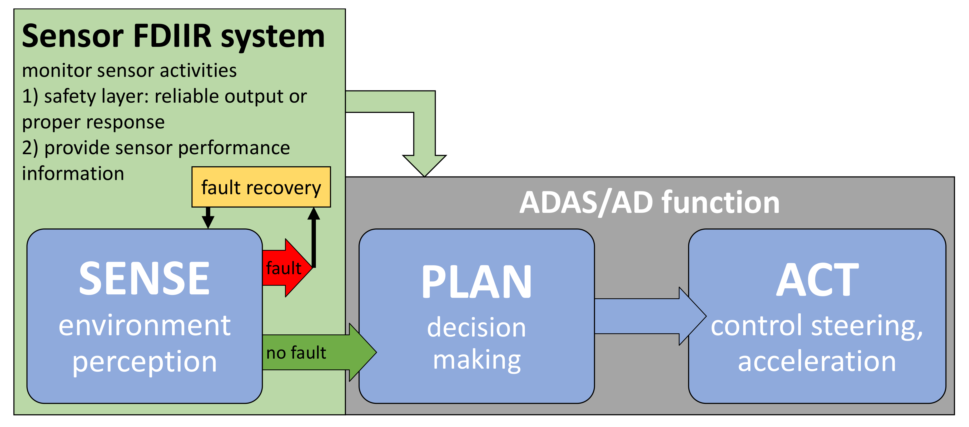
:1. Introduction
- Identify all types of faults, detection methods, and recovery methods for automotive perception sensors and develop a corresponding classification schema.
- Evaluate the state of the art of FDIIR methods for automotive lidar.
- Explain, discuss, and compare the most promising existing FDIIR methods for automotive lidar.
- Identify research opportunities related to FDIIR methods for automotive lidar.
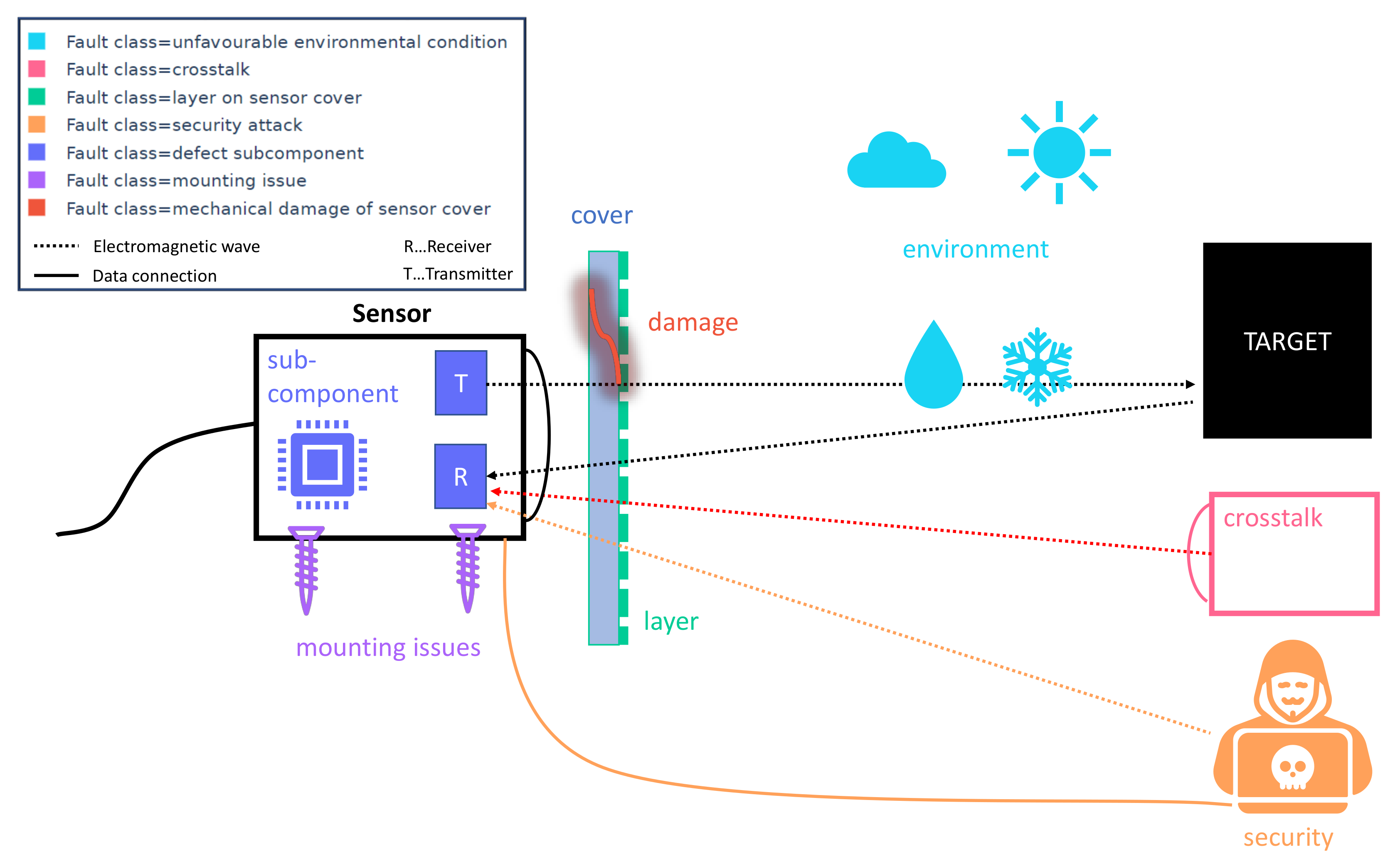
2. Classification of Faults of Perception Sensors
International Safety Standards Addressing Faults of Perception Sensors
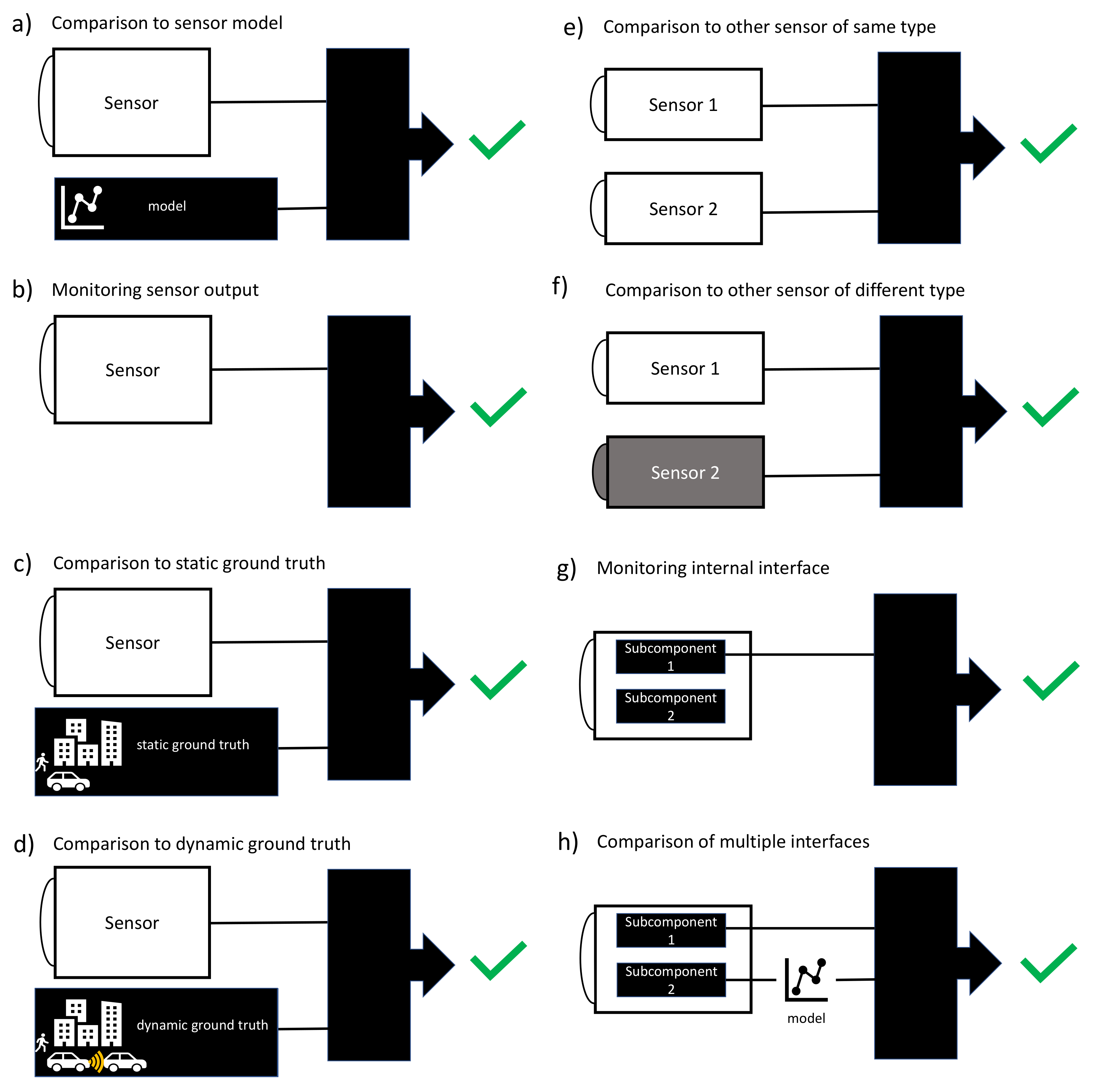
3. Classification of FDII Methods for Perception Sensors
4. Classification of Recovery Methods for Perception Sensors
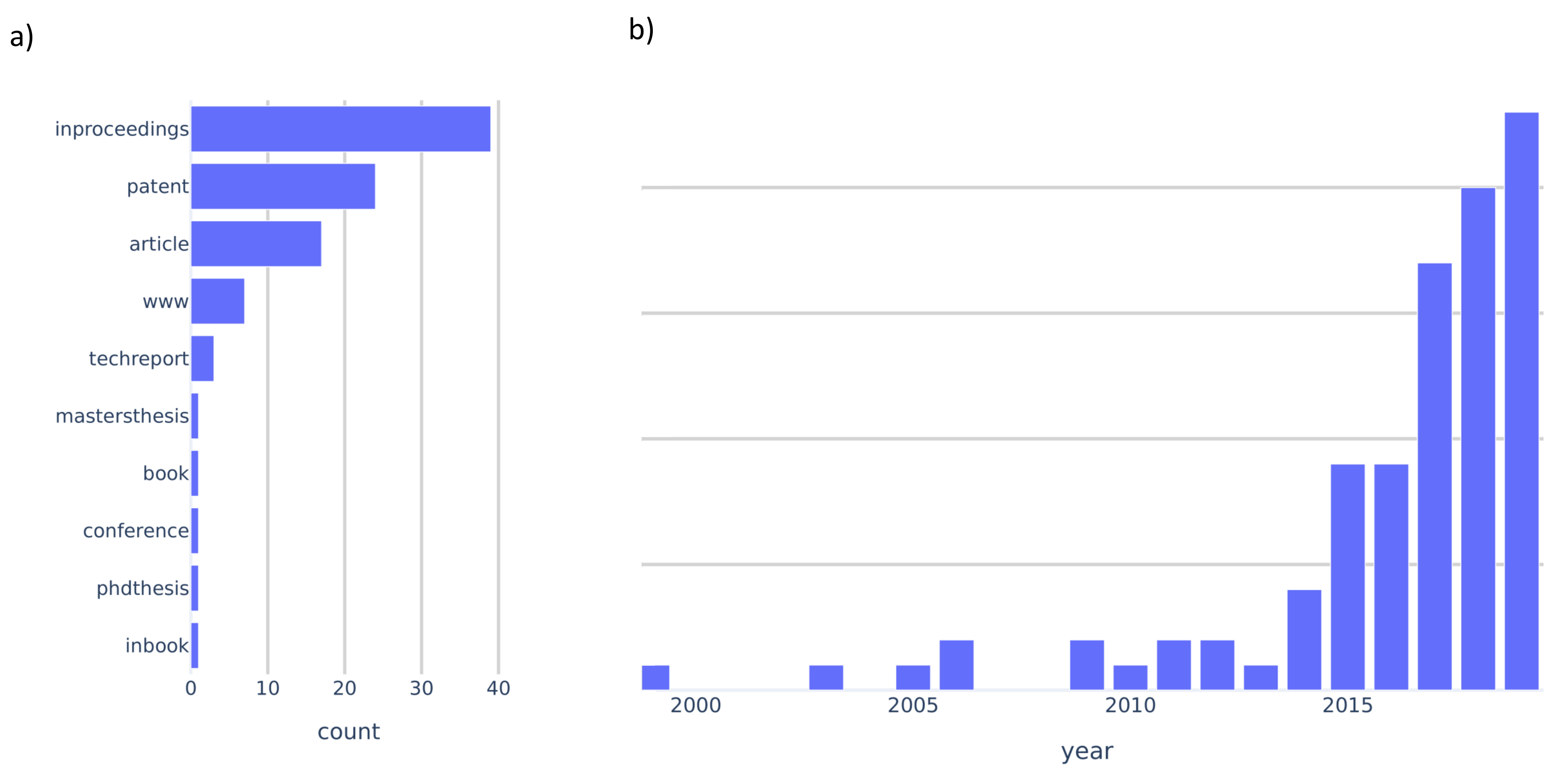
5. Literature Survey Methodology
6. Literature Survey on FDIIR Methods for Automotive Lidar
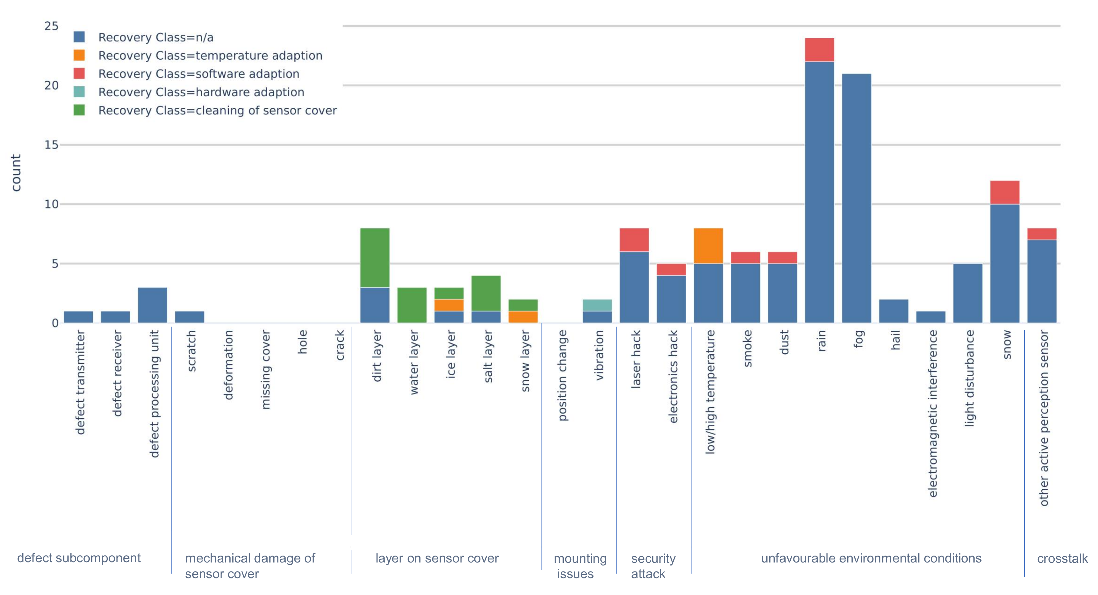
6.1. Fault Classes of Automotive Lidar
6.2. FDII Classes and Realizations for Automotive Lidar
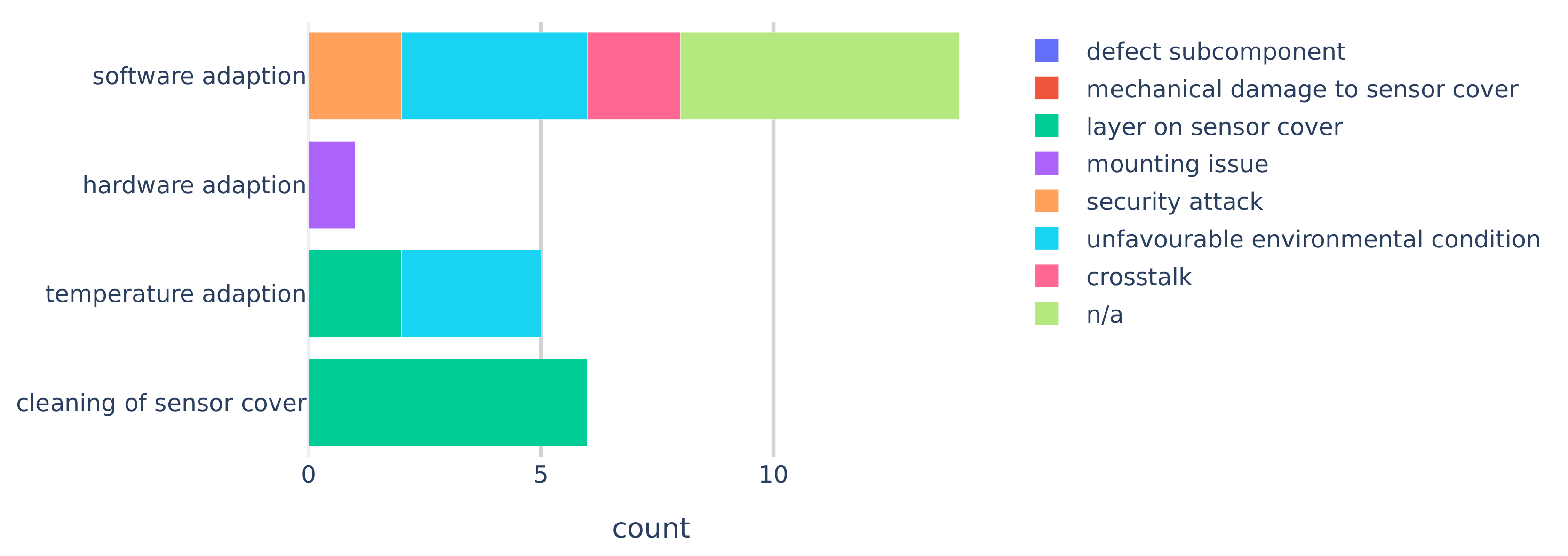
6.3. Recovery Methods for Automotive Lidar
7. Discussion and Conclusions
7.1. Limitations of the Literature Study
7.2. Faults and Fault Classes
7.3. Fault Detection, Isolation, and Identification
7.4. Recovery Methods
7.5. Research Opportunities
- Mounting issues and mechanical damage to the sensor cover have been studied very little.
- Comparison to static and dynamic ground truth are very promising FDII methods. Still, these methods require more research to evaluate which and how ground truth information can be accessed by the FDIIR system.
- Although unfavourable environmental conditions have been discussed in many publications, possible recovery methods for this fault class were typically absent.
- Literature on defective subcomponents is sparse and no suitable recovery methods were described. This is most likely because commercial lidar units are provided as “black box”, because manufacturers are very protective of their intellectual properties. This calls for an open standard in order to access interfaces between subcomponents.
- Due to similar reasons, fault detection, isolation, and identification methods that access internal interfaces are mentioned only once in the literature.
- Detailed investigations of first principles of root causes for faults could lead to fault detection and recovery methods that apply for a wide range of faults.
- Hardware adaption has been studies very little and might be well suited for other faults related to mounting issues.
7.6. Closing Remarks
Author Contributions
Funding
Acknowledgments
Conflicts of Interest
Abbreviations
| AD | Automated Driving |
| ADAS | Advanced Driver-Assistance Systems |
| ASIL | Automotive Safety Integrity Level |
| FDIIR | Fault Detection Isolation Identification Recovery |
| FOV | Field Of View |
| MEMS | MicroElectroMechanical Systems |
| SAE | Society of Automotive Engineers |
| V2V | Vehicle-to-vehicle communication |
| V2X | Vehicle-to-everything communication |
References
- Watzenig, D.; Horn, M. (Eds.) Automated Driving—Safer and More Efficient Future Driving; Springer International Publishing: Cham, Switzerland, 2017. [Google Scholar] [CrossRef]
- World Health Organisation. Global Status Report on Road Safety 2018; Technical Report; World Health Organisation: Geneva, Switzerland, 2018. [Google Scholar]
- Anderson, J.; Kalra, N.; Stanley, K.; Sorensen, P.; Samaras, C.; Oluwatola, T. Autonomous Vehicle Technology: A Guide for Policymakers; RAND Corporation: Santa Monica, CA, USA, 2014. [Google Scholar]
- Fagnant, D.J.; Kockelman, K. Preparing a nation for autonomous vehicles: Opportunities, barriers and policy recommendations. Transp. Res. Part A Policy Pract. 2015, 77, 167–181. [Google Scholar] [CrossRef]
- Thomas, P.; Morris, A.; Talbot, R.; Fagerlind, H. Identifying the causes of road crashes in Europe. Ann. Adv. Automot. Medicine. Assoc. Adv. Automot. Med. Annu. Sci. Conf. 2013, 57, 13–22. [Google Scholar]
- SAE International. Taxonomy and Definitions for Terms Related to Driving Automation Systems for on-Road Motor Vehicles; SAE International: Warrendale, PA, USA, 2018. [Google Scholar] [CrossRef]
- Marti, E.; de Miguel, M.A.; Garcia, F.; Perez, J. A Review of Sensor Technologies for Perception in Automated Driving. IEEE Intell. Transp. Syst. Mag. 2019, 11, 94–108. [Google Scholar] [CrossRef]
- Isermann, R. Fault-Diagnosis Systems: An Introduction from Fault Detection to Fault Tolerance; Springer: Berlin, Germany, 2006. [Google Scholar]
- RobustSENSE. Available online: http://www.robustsense.eu/ (accessed on 12 January 2020).
- Dense. Available online: https://dense247.eu (accessed on 17 October 2019).
- Hecht, J. Lidar for Self-Driving Cars. Opt. Photonics News 2018, 29, 26–33. [Google Scholar] [CrossRef]
- Thakur, R. Scanning LIDAR in Advanced Driver Assistance Systems and Beyond: Building a road map for next-generation LIDAR technology. IEEE Consum. Electron. Mag. 2016, 5, 48–54. [Google Scholar] [CrossRef]
- Warren, M.E. Automotive LIDAR Technology. In Proceedings of the 2019 Symposium on VLSI Circuits, Kyoto, Japan, 9–14 June 2019; pp. C254–C255. [Google Scholar] [CrossRef]
- Druml, N.; Maksymova, I.; Thurner, T.; Lierop, D.; Hennecke, M.; Foroutan, A. 1D MEMS Micro-Scanning LiDAR. In Proceedings of the International Conference on Sensor Device Technologies and Applications (SENSORDEVICES), Venice, Italy, 16–20 September 2018. [Google Scholar]
- Petit, J.; Shladover, S.E. Potential cyberattacks on automated vehicles. IEEE Trans. Intell. Transp. Syst. 2014, 16, 546–556. [Google Scholar] [CrossRef]
- Shin, H.; Kim, D.; Kwon, Y.; Kim, Y. Illusion and Dazzle: Adversarial Optical Channel Exploits against Lidars for Automotive Applications. In Lecture Notes in Computer Science; Springer International Publishing: Cham, Switzerland, 2018; pp. 445–467. [Google Scholar] [CrossRef]
- Kim, G.; Eom, J.; Park, Y. An Experiment of Mutual Interference between Automotive LIDAR Scanners. In Proceedings of the 2015 12th International Conference on Information Technology—New Generations, Las Vegas, NV, USA, 13–15 April 2015; pp. 680–685. [Google Scholar] [CrossRef]
- Zhang, F.; Liu, Q.; Gong, M.; Fu, X. Anti-dynamic-crosstalk method for single photon LIDAR detection. In Proceedings of the SPIE 10605, LIDAR Imaging Detection and Target Recognition 2017, Bellingham, WA, USA, 23–25 July 2017; Lv, Y., Su, J., Gong, W., Yang, J., Bao, W., Chen, W., Shi, Z., Fei, J., Han, S., Jin, W., Eds.; International Society for Optics and Photonics: Bellingham, WA, USA, 2017; Volume 10605, p. 1060503. [Google Scholar] [CrossRef]
- ISO26262. 26262: Road Vehicles-Functional Safety; International Standard; International Organization for Standardization: Geneva, Switzerland, 2011. [Google Scholar]
- ISO/PAS 21448:2019. Road Vehicles—Safety of the Intended Functionality; Technical Report; International Organization for Standardization: Geneva, Switzerland, 2019. [Google Scholar]
- Chen, J.; Patton, R. Robust Model-based Fault Diagnosis for Dynamic Systems, 1st ed.; Springer: New York, NY, USA, 1999; Volume 3. [Google Scholar] [CrossRef]
- Chen, X.; Wang, Z.; Zhang, Z.; Jia, L.; Qin, Y. A Semi-Supervised Approach to Bearing Fault Diagnosis under Variable Conditions towards Imbalanced Unlabeled Data. Sensors 2018, 18, 2097. [Google Scholar] [CrossRef] [Green Version]
- Piltan, F.; Kim, J.M. Bearing Fault Diagnosis by a Robust Higher-Order Super-Twisting Sliding Mode Observer. Sensors 2018, 18, 1128. [Google Scholar] [CrossRef] [PubMed] [Green Version]
- Liberati, A.; Altman, D.G.; Tetzlaff, J.; Mulrow, C.; Gøtzsche, P.C.; Ioannidis, J.P.A.; Clarke, M.; Devereaux, P.J.; Kleijnen, J.; Moher, D. The PRISMA Statement for Reporting Systematic Reviews and Meta-Analyses of Studies That Evaluate Health Care Interventions: Explanation and Elaboration. PLoS Med. 2009, 6, 1–28. [Google Scholar] [CrossRef] [PubMed]
- Yunusa-Kaltungo, A.; Labib, A. A hybrid of industrial maintenance decision making grids. Prod. Plan. Control 2020, 1–18. [Google Scholar] [CrossRef]
- Segata, M.; Cigno, R.L.; Bhadani, R.K.; Bunting, M.; Sprinkle, J. A LiDAR Error Model for Cooperative Driving Simulations. In Proceedings of the 2018 IEEE Vehicular Networking Conference (VNC), Taipei, Taiwan, 5–7 December 2018; pp. 1–8. [Google Scholar] [CrossRef] [Green Version]
- Sun, X.H. Method and Apparatus for Detection and Ranging Fault Detection and Recovery. U.S. Patent 010203408B, 12 February 2019. [Google Scholar]
- Ibeo. Ethernet Data Protocol Ibeo LUX and Ibeo LUX Systems; Technical Report; Ibeo: Hamburg, Germany, 2009. [Google Scholar]
- Rivero, J.R.V.; Tahiraj, I.; Schubert, O.; Glassl, C.; Buschardt, B.; Berk, M.; Chen, J. Characterization and simulation of the effect of road dirt on the performance of a laser scanner. In Proceedings of the 2017 IEEE 20th International Conference on Intelligent Transportation Systems (ITSC), Yokohama, Japan, 16–19 October 2017; pp. 1–6. [Google Scholar] [CrossRef]
- Tegler, E. Available online: https://www.popularmechanics.com/cars/car-technology/a29309664/bugs-self-driving-cars/ (accessed on 17 September 2019).
- Trierweiler, M.; Caldelas, P.; Gröninger, G.; Peterseim, T.; Neumann, C. Influence of sensor blockage on automotive LiDAR systems. In Proceedings of the 2019 IEEE SENSORS, Montreal, QC, Canada, 27–30 October 2019; pp. 1–4. [Google Scholar] [CrossRef]
- Jalopnik. Available online: https://jalopnik.com/google-has-a-wiper-for-its-lidar-to-handle-bird-shit-an-1795346982 (accessed on 5 October 2019).
- James, J.K.; Puhlfürst, G.; Golyanik, V.; Stricker, D. Classification of LIDAR Sensor Contaminations with Deep Neural Networks. In Proceedings of the Computer Science in Cars Symposium (CSCS) 2018, Munich, Germany, 13–14 September 2018; p. 8. [Google Scholar] [CrossRef]
- Green, A.; Bidner, D.K. Lidar Windscreen Vibration Control. U.S. Patent 20190359179A1, 28 November 2019. [Google Scholar]
- Zhao, C.; Gopalan, S. Automotive Image Sensor Surface Washing and Drying System. U.S. Patent 20190202410A, 4 July 2019. [Google Scholar]
- Wideye. Available online: https://www.wideye.vision/use-cases-value/lidar-covers/ (accessed on 17 September 2019).
- Doorley, G.; Karplus, P.T.H.; Avram, P. Control for Passive Wiper System. U.S. Patent 2017/0151933 A1, 1 June 2017. [Google Scholar]
- McMichael, R.; Kentley-Klay, T.D.; Schabb, D.E.; Thakur, A.; Torrey, J. Sensor Obstruction Detection and Mitigation Using Vibration and/ot Heat. U.S. Patent WO 2019246029A1, 19 December 2019. [Google Scholar]
- Periu, C.; Mohsenimanesh, A.; Laguë, C.; McLaughlin, N. Isolation of Vibrations Transmitted to a LIDAR Sensor Mounted on an Agricultural Vehicle to Improve Obstacle Detection. Can. Biosyst. Eng. 2013, 55, 233–242. [Google Scholar] [CrossRef] [Green Version]
- Hama, S.; Toda, H. Basic Experiment of LIDAR Sensor Measurement Directional Instability for Moving and Vibrating Object. In Proceedings of the 6th Annual International Conference on Material Science and Environmental Engineering, Chongqing, China, 23–25 November 2018; IOP Conference Series-Materials Science and Engineering. Wang, K., Ed.; IOP Publishing Ltd.: Bristol, UK, 2019; Volume 472. [Google Scholar] [CrossRef] [Green Version]
- McManamon, P. Field Guide to Lidar; SPIE Field Guides; SPIE: Bellingham, WA, USA, 2015; Volume FG36. [Google Scholar]
- Stottelaar, B.G. Practical Cyber-Attacks on Autonomous Vehicles. Master’s Thesis, University of Twente, Enschede, The Netherlands, 2015. [Google Scholar]
- Guo, P.; Kim, H.; Virani, N.; Xu, J.; Zhu, M.; Liu, P. RoboADS: Anomaly Detection Against Sensor and Actuator Misbehaviors in Mobile Robots. In Proceedings of the 2018 48th Annual IEEE/IFIP International Conference on Dependable Systems and Networks (DSN), Luxembourg, 25–28 June 2018; pp. 574–585. [Google Scholar] [CrossRef]
- Petit, J.; Stottelaar, B.; Feiri, M.; Kargl, F. Remote attacks on automated vehicles sensors: Experiments on camera and lidar. Black Hat Eur. 2015, 11, 2015. [Google Scholar]
- Thing, V.L.L.; Wu, J. Autonomous Vehicle Security: A Taxonomy of Attacks and Defences. In Proceedings of the 2016 IEEE International Conference on Internet of Things (iThings) and IEEE Green Computing and Communications (GreenCom) and IEEE Cyber, Physical and Social Computing (CPSCom) and IEEE Smart Data (SmartData), Chengdu, China, 15–18 December 2016; pp. 164–170. [Google Scholar] [CrossRef]
- Choi, H.; Lee, W.C.; Aafer, Y.; Fei, F.; Tu, Z.; Zhang, X.; Xu, D.; Deng, X. Detecting Attacks Against Robotic Vehicles: A Control Invariant Approach. In Proceedings of the 2018 ACM SIGSAC Conference on Computer and Communications Security, CCS ’18, Toronto, ON, Canada, 15–19 October 2018; ACM: New York, NY, USA, 2018; pp. 801–816. [Google Scholar] [CrossRef]
- Dutta, R.G. Security of Autonomous Systems Under Physical Attacks: With Application to Self-Driving Cars. Ph.D. Thesis, University of Central Florida, Orlando, FL, USA, 2018. [Google Scholar]
- Zang, S.; Ding, M.; Smith, D.; Tyler, P.; Rakotoarivelo, T.; Kaafar, M.A. The Impact of Adverse Weather Conditions on Autonomous Vehicles: How Rain, Snow, Fog, and Hail Affect the Performance of a Self-Driving Car. IEEE Veh. Technol. Mag. 2019, 14, 103–111. [Google Scholar] [CrossRef]
- Filgueira, A.; González-Jorge, H.; Lagüela, S.; Díaz-Vilariño, L.; Arias, P. Quantifying the influence of rain in LiDAR performance. Measurement 2017, 95, 143–148. [Google Scholar] [CrossRef]
- Hasirlioglu, S.; Doric, I.; Kamann, A.; Riener, A. Reproducible Fog Simulation for Testing Automotive Surround Sensors. In Proceedings of the 2017 IEEE 85th Vehicular Technology Conference (VTC Spring), Sydney, NSW, Australia, 4–7 June 2017; pp. 1–7. [Google Scholar] [CrossRef]
- Kim, B.K.; Sumi, Y. Performance evaluation of safety sensors in the indoor fog chamber. In Proceedings of the 2017 IEEE Underwater Technology (UT), Busan, Korea, 21–24 February 2017; pp. 1–3. [Google Scholar] [CrossRef]
- Dannheim, C.; Icking, C.; Mader, M.; Sallis, P. Weather Detection in Vehicles by Means of Camera and LIDAR Systems. In Proceedings of the 2014 Sixth International Conference on Computational Intelligence, Communication Systems and Networks, Tetova, Macedonia, 27–29 May 2014; pp. 186–191. [Google Scholar] [CrossRef]
- RobustSENSE. Deliverable D5.1 System Performance Assessment Specification; Technical Report; RobustSENSE: Ulm, Germany, 2016. [Google Scholar]
- Hasirlioglu, S.; Riener, A. Introduction to Rain and Fog Attenuation on Automotive Surround Sensors. In Proceedings of the 2017 IEEE 20th International Conference on Intelligent Transportation Systems (ITSC), Yokohama, Japan, 16–19 October 2017. [Google Scholar] [CrossRef]
- Mäyrä, A.; Hietala, E.; Kutila, M.; Pyykönen, P. Spectral attenuation in low visibility artificial fog: Experimental study and comparison to literature models. In Proceedings of the 2017 13th IEEE International Conference on Intelligent Computer Communication and Processing (ICCP), Cluj-Napoca, Romania, 7–9 September 2017; pp. 303–308. [Google Scholar] [CrossRef]
- Mäyrä, A.; Hietala, E.; Kutila, M.; Pyykönen, P.; Tiihonen, M.; Jokela, T. Experimental study on spectral absorbance in fog as a function of temperature, liquid water content, and particle size. In Optics in Atmospheric Propagation and Adaptive Systems; International Society for Optics and Photonics: Bellingham, WA, USA, 2017; Volume 10425, p. 104250G. [Google Scholar] [CrossRef]
- Heinzler, R.; Schindler, P.; Seekircher, J.; Ritter, W.; Stork, W. Weather Influence and Classification with Automotive Lidar Sensors. In Proceedings of the 2019 IEEE Intelligent Vehicles Symposium (IV), Paris, France, 9–12 June 2019; IEEE: Piscataway, NJ, USA, 2019; pp. 1527–1534. [Google Scholar] [CrossRef] [Green Version]
- Aho, A.T.; Viheriälä, J.; Mäkelä, J.; Virtanen, H.; Ranta, S.; Dumitrescu, M.; Guina, M. High-power 1550 nm tapered DBR laser diodes for LIDAR applications. In Proceedings of the 2017 Conference on Lasers and Electro-Optics Europe European Quantum Electronics Conference (CLEO/Europe-EQEC), Munich, Germany, 25–29 June 2017. [Google Scholar] [CrossRef]
- Goodin, C.; Carruth, D.; Doude, M.; Hudson, C. Predicting the Influence of Rain on LIDAR in ADAS. Electronics 2019, 8, 89. [Google Scholar] [CrossRef] [Green Version]
- Ruiz-Llata, M.; Rodriguez-Cortina, M.; Martin-Mateos, P.; Bonilla-Manrique, O.E.; Ramon Lopez-Fernandez, J. LiDAR design for Road Condition Measurement ahead of a moving vehicle. In Proceedings of the 2017 16th IEEE Sensors, IEEE Sensors, Glasgow, UK, 29 October–1 November 2017; pp. 1062–1064. [Google Scholar] [CrossRef] [Green Version]
- Rosique, F.; Navarro, P.J.; Fernández, C.; Padilla, A. A Systematic Review of Perception System and Simulators for Autonomous Vehicles Research. Sensors 2019, 19, 648. [Google Scholar] [CrossRef] [Green Version]
- Daniel, L.; Phippen, D.; Hoare, E.; Stove, A.; Cherniakov, M.; Gashinova, M. Low-THz radar, lidar and optical imaging through artificially generated fog. In Proceedings of the International Conference on Radar Systems 2017, Belfast, UK, 23–26 October 2017; pp. 1–4. [Google Scholar] [CrossRef]
- Rasshofer, R.H.; Spies, M.; Spies, H. Influences of weather phenomena on automotive laser radar systems. Adv. Radio Sci. 2011, 9, 49–60. [Google Scholar] [CrossRef] [Green Version]
- Xique, I.J.; Buller, W.; Fard, Z.B.; Dennis, E.; Hart, B. Evaluating Complementary Strengths and Weaknesses of ADAS Sensors. In Proceedings of the 2018 IEEE 88th Vehicular Technology Conference (VTC-Fall), Chicago, IL, USA, 27–30 August 2018; pp. 1–5. [Google Scholar]
- Kutila, M.; Pyykonen, P.; Ritter, W.; Sawade, O.; Schaufele, B. Automotive LIDAR sensor development scenarios for harsh weather conditions. In Proceedings of the 2016 IEEE 19th International Conference on Intelligent Transportation Systems (ITSC), Rio de Janeiro, Brazil, 1–4 November 2016; pp. 265–270. [Google Scholar] [CrossRef]
- Phillips, T.G.; Guenther, N.; McAree, P.R. When the Dust Settles: The Four Behaviors of LiDAR in the Presence of Fine Airborne Particulates. J. Field Robot. 2017, 34, 985–1009. [Google Scholar] [CrossRef]
- Wilson, J.; Sinha, P. Thermal Considerations For Designing Reliable and Safe Autonomous Vehicle Sensors. Available online: https://www.fierceelectronics.com/components/thermal-considerations-for-designing-reliable-and-safe-autonomous-vehicle-sensors (accessed on 25 September 2019).
- Hasirlioglu, S.; Riener, A.; Huber, W.; Wintersberger, P. Effects of exhaust gases on laser scanner data quality at low ambient temperatures. In Proceedings of the 2017 IEEE Intelligent Vehicles Symposium (IV), Los Angeles, CA, USA, 11–14 June 2017; pp. 1708–1713. [Google Scholar] [CrossRef]
- Hasirlioglu, S.; Kamann, A.; Doric, I.; Brandmeier, T. Test methodology for rain influence on automotive surround sensors. In Proceedings of the 2016 IEEE 19th International Conference on Intelligent Transportation Systems (ITSC), Rio de Janeiro, Brazil, 1–4 November 2016; pp. 2242–2247. [Google Scholar] [CrossRef]
- Moorehead, S.; Simmons, R.; Apostolopoulos, D.D.; Whittaker, W.R.L. Autonomous Navigation Field Results of a Planetary Analog Robot in Antarctica. In Proceedings of the International Symposium on Artificial Intelligence, Robotics and Automation in Space, Noordwijk, The Netherlands, 1–3 June 1999. [Google Scholar]
- Pfeuffer, A.; Dietmayer, K. Optimal Sensor Data Fusion Architecture for Object Detection in Adverse Weather Conditions. arXiv 2018, arXiv:1807.02323. [Google Scholar]
- Sick. Available online: https://lidarnews.com/articles/top-5-considerations-for-choosing-lidar-for-outdoor-robots/ (accessed on 25 September 2019).
- Waterloo Autonomous Vehicles Lab. Available online: http://wavelab.uwaterloo.ca/?weblizar_portfolio=real-time-filtering-of-snow-from-lidar-point-clouds (accessed on 25 September 2019).
- Zhang, C.; Ang, M.H.; Rus, D. Robust LIDAR Localization for Autonomous Driving in Rain. In Proceedings of the 2018 IEEE/RSJ International Conference on Intelligent Robots and Systems (IROS), Madrid, Spain, 1–5 October 2018; pp. 3409–3415. [Google Scholar] [CrossRef]
- Peynot, T.; Underwood, J.; Scheding, S. Towards reliable perception for Unmanned Ground Vehicles in challenging conditions. In Proceedings of the 2009 IEEE/RSJ International Conference on Intelligent Robots and Systems, St. Louis, MO, USA, 10–15 October 2009; pp. 1170–1176. [Google Scholar] [CrossRef] [Green Version]
- Bijelic, M.; Gruber, T.; Ritter, W. A Benchmark for Lidar Sensors in Fog: Is Detection Breaking Down? In Proceedings of the 2018 IEEE Intelligent Vehicles Symposium (IV), Changshu, China, 26–30 June 2018. [Google Scholar] [CrossRef] [Green Version]
- Hasirlioglu, S.; Riener, A. A Model-based Approach to Simulate Rain Effects on Automotive Surround Sensor Data. In Proceedings of the 2018 21st International Conference on Intelligent Transportation Systems (ITSC), Maui, HI, USA, 4–7 November 2018; pp. 2609–2615. [Google Scholar] [CrossRef]
- Ijaz, M.; Ghassemlooy, Z.; Minh, H.L.; Rajbhandari, S.; Perez, J. Analysis of Fog and Smoke Attenuation in a Free Space Optical Communication Link. In Proceedings of the 2012 International Workshop on Optical Wireless Communications (IWOW), Pisa, Italy, 22 October 2012; pp. 1–3. [Google Scholar]
- Fersch, T.; Buhmann, A.; Koelpin, A.; Weigel, R. The Influence and of Rain on Small Aperture and LiDAR Sensors. In Proceedings of the German Microwave Conference (GeMiC) 2016, Bochum, Germany, 14–16 March 2016. [Google Scholar]
- Hadj-Bachir, M.; Souza, P. LIDAR Sensor Simulation in Adverse Weather Condition for Driving Assistance Development; hal-01998668; Hyper Articles en Ligne (HAL): Lyon, France, 2019. [Google Scholar]
- Kutila, M.; Pyykönen, P.; Holzhüter, H.; Colomb, M.; Duthon, P. Automotive LiDAR performance verification in fog and rain. In Proceedings of the 2018 21st International Conference on Intelligent Transportation Systems (ITSC), Maui, HI, USA, 4–7 November 2018; pp. 1695–1701. [Google Scholar] [CrossRef]
- Hasirlioglu, S.; Doric, I.; Lauerer, C.; Brandmeier, T. Modeling and simulation of rain for the test of automotive sensor systems. In Proceedings of the 2016 IEEE Intelligent Vehicles Symposium (IV), Gotenburg, Sweden, 19–22 June 2016; pp. 286–291. [Google Scholar] [CrossRef]
- Schönhuber, M. Available online: https://www.distrometer.at/2dvd/ (accessed on 13 September 2019).
- Jokela, M.; Kutila, M.; Pyykönen, P. Testing and Validation of Automotive Point-Cloud Sensors in Adverse Weather Conditions. Appl. Sci. 2019, 9, 2341. [Google Scholar] [CrossRef] [Green Version]
- Michaud, S.; Lalonde, J.F.; Giguere, P. Towards Characterizing the Behavior of LiDARs in Snowy Conditions. In Proceedings of the 7th Workshop on Planning, Perception and Navigation for Intelligent Vehicles, Hamburg, Germany, 28 September 2015. [Google Scholar]
- Sick. Available online: https://www.sick.com/ag/en/detection-and-ranging-solutions/2d-lidar-sensors/lms1xx/c/g91901 (accessed on 18 October 2019).
- O’Brien, M.E.; Fouche, D.G. Simulation of 3D Laser Radar Systems. Linc. Lab. J. 2005, 15, 37–60. [Google Scholar]
- McKnight, D.; Miles, R. Impact of reduced visibility conditions on laser based DP sensors. In Proceedings of the Dynamic Positioning Conference, Houston, TX, USA, 14–15 October 2014. [Google Scholar]
- Lingg, A.J.; Beck, S.W.; Stepanian, J.G.; Clifford, D.H. Method and Apparatus Crosstalk and Multipath Noise Reduction in A Lidar System. U.S. Patent 2019/0339393A1, 7 November 2019. [Google Scholar]
- Diehm, A.L.; Hammer, M.; Hebel, M.; Arens, M. Mitigation of crosstalk effects in multi-LiDAR configurations. In Proceedings of the Electro-Optical Remote Sensing XII, Berlin, Germany, 12–13 September 2018; Kamerman, G., Steinvall, O., Eds.; SPIE: Washington, DC, USA, 2018; Volume 10796. [Google Scholar] [CrossRef]
- Retterath, J.E.; Laumeyer, R.A. Methods and Apparatus for Array Based LiDAR Systems With Reduced Interference. U.S. Patent 10,203,399, 12 February 2019. [Google Scholar]
- Denham, M.; Gilliland, P.B.; Goldstein, B.M.; Musa, O. Crosstalk Mitigation Circuit for Lidar Pixel Receivers. U.S. Patent 2019/0317196A1, 17 October 2019. [Google Scholar]
- Hall, D.S. High Definition LiDAR System. U.S. Patent 7969558B2, 28 June 2011. [Google Scholar]
- Eichenholz, J.M.; LaChapelle, J.G. Detection of Crosstalk and Jamming Pulses With Lidar System. U.S. Patent 16/178,049, 2 May 2019. [Google Scholar]
- Huang, W.; Su, X. Design of a Fault Detection and Isolation System for Intelligent Vehicle Navigation System. Int. J. Navig. Obs. 2015, 2015, 1–19. [Google Scholar] [CrossRef] [Green Version]
- Qin, S.J.; Guiver, J.P. Sensor Validation Apparatus and Method. U.S. Patent 6594620B1, 15 July 2003. [Google Scholar]
- Song, J.; Fry, G.; Wu, C.; Parmer, G. CAML: Machine Learning-based Predictable, System-Level Anomaly Detection. In Proceedings of the 1st Workshop on Security and Dependability of Critical Embedded Real-Time Systems, in Conjunction with IEEE Real-Time Systems Symposium, Porto, Portugal, 29 November 2016. [Google Scholar]
- Breed, D.S. System and Method for Vehicle Diagnostics. U.S. Patent 7103460B1, 5 September 2006. [Google Scholar]
- Leslar, M.; Wang, J.; Hu, B. A Comparison of Two New Methods of Outlier Detection for Mobile Terrestrial Lidar Data. Proc. Int. Arch. Photogramm. Remote Sens. Spatial Inf. Sci. 2010, 38, 78–84. [Google Scholar]
- Khalastchi, E.; Kaminka, G.; Lin, R.; Kalech, M. Anomaly Detection Methods, Devices and Systems. U.S. Patent 2014/0149806A1, 29 May 2014. [Google Scholar]
- Tascione, D.; Bode, M. Autonomous Vehicle Diagnostic System. U.S. Patent 2018/0050704A1, 22 February 2018. [Google Scholar]
- Abt, T.L.; Hirsenkorn, K.; Isert, C.; Parolini, L.; Radler, S.; Rauch, S. Method, System, and Computer Program Product for Determining a Blockage of a Sensor of a Plurality of Sensors of an Ego Vehicle. EP 3511740A1, 17 July 2019. [Google Scholar]
- Mori, D.; Sugiura, H.; Hattori, Y. Adaptive Sensor Fault Detection and Isolation using Unscented Kalman Filter for Vehicle Positioning. In Proceedings of the 2019 IEEE Intelligent Transportation Systems Conference (ITSC), Auckland, New Zealand, 27–30 October 2019; pp. 1298–1304. [Google Scholar] [CrossRef]
- Bruns, E.; Venator, M. Verfahren und Steuervorrichtung zum Erkennen einer Fehlfunktion zumindest eines Umfeldsensors eines Kraftfahrzeugs. DE 102018205322A1, 10 April 2019. [Google Scholar]
- Zhu, J.; Ferguson, D.I. System to Optimize Sensor Parameters in an Autonomous Vehicle. U.S. Patent 2018/0329423A1, 15 November 2018. [Google Scholar]
- Mehrdad, S.K. Verfahren Zum Verarbeiten Von Sensordaten, Anordnung Zur Verarbeitung Von Sensordaten, Anordnung Zum Verarbeiten Einer Anfrage Eines Ego-Fahrzeugs Für Ein Weiteres Fahrzeug, Rechner Zum Verarbeiten Von Sensordaten Sowie Rechner Zum Verarbeiten Einer Anfrage Eines Ego-Fahrzeugs Für Ein Weiteres Fahrzeug. DE 102018207658A1, 21 November 2019. [Google Scholar]
- Ghimire, S.; Prokhorov, D. Collaborative Multi-Agent Vehicle Fault Diagnostic System & Associated Methodology. WO 2012/148514 A1, 1 November 2012. [Google Scholar]
- Zhu, J.; Dolgov, D.A.; Urmson, C.P. Cross-Validating Sensors of an Autonomous Vehicle. U.S. Patent 9555740B1, 31 January 2017. [Google Scholar]
- Kim, H.S.; Seo, M.W.; Yang, J.W.; Kim, S.Y.; Yang, D.H.; Ko, B.C.; Seo, G.W. Apparatus and Method for Failure Diagnosis and Calibration of Sensors for advanced Driver Assistance Systems. U.S. Patent 10026239B2, 17 July 2018. [Google Scholar]
- Zhu, J.; Dolgov, D.; Urmson, C.P. Cross-Validating Sensors of an Autonomous Vehicle. U.S. Patent 9221396B1, 29 December 2015. [Google Scholar]
- Hartung, J.J.; Brink, P.; Lamb, J.; Miller, D.P. Autonomous Vehicle Platform and Safety Architecture. U.S. Patent 2017139411A1, 18 May 2017. [Google Scholar]
- Gao, B.; Coifman, B. Vehicle identification and GPS error detection from a LIDAR equipped probe vehicle. In Proceedings of the 2006 IEEE Intelligent Transportation Systems Conference, Toronto, ON, Canada, 17–20 September 2006; pp. 1537–1542. [Google Scholar] [CrossRef]
- Egnor, D.T.; Zbrozek, A.; Schultz, A. Methods and Systems for Compensating for Common Failures. U.S. Patent 9,195.232 B1, 24 November 2015. [Google Scholar]
- Ning, X.; Li, F.; Tian, G.; Wang, Y. An efficient outlier removal method for scattered point cloud data. PLoS ONE 2018, 13, e0201280. [Google Scholar] [CrossRef] [Green Version]
- Shin, B. Fault Tolerant Control and Localization for Autonomous Driving: Systems and Architecture; Technical Report UCB/EECS-2016-83; University of California at Berkeley: Berkeley, CA, USA, 2016. [Google Scholar]
- Sazara, C.; Nezafat, R.V.; Cetin, M. Offline reconstruction of missing vehicle trajectory data from 3D LIDAR. In Proceedings of the 2017 IEEE Intelligent Vehicles Symposium (IV), Los Angeles, CA, USA, 11–14 June 2017; pp. 792–797. [Google Scholar] [CrossRef] [Green Version]
- Avlas, L.N.; Berseth, E.N. Systems and methods for mitigating optical crosstalk in a light ranging and detection system. U.S. Patent 2020/0064452A1, 27 February 2020. [Google Scholar]
- El-Nayal, M.K.; Aly, M.M.; Fayed, H.A.; AbdelRassoul, R.A. Adaptive free space optic system based on visibility detector to overcome atmospheric attenuation. Results Phys. 2019, 14, 102392. [Google Scholar] [CrossRef]
- Colomb, M.; Duthon, P.; Laukkanen, S. Characteristics of Adverse Weather Conditions; Technical Report, DENSE247.eu; DENSE Consortium: Ulm, Germany, 2017. [Google Scholar]
- Hespel, L.; Riviere, N.; Huet, T.; Tanguy, B.; Ceolato, R. Performance evaluation of laser scanners through the atmosphere with adverse condition. In Electro-Optical Remote Sensing, Photonic Technologies, and Applications V; Kamerman, G.W., Steinvall, O., Bishop, G.J., Gonglewski, J.D., Lewis, K.L., Hollins, R.C., Merlet, T.J., Eds.; International Society for Optics and Photonics: Bellingham, WA, USA, 2011; Volume 8186, p. 818606. [Google Scholar] [CrossRef]


| Fault Class | Exemplary Fault | Safety Standard |
|---|---|---|
| defect subcomponent | defect transmitter | ISO 26262 |
| defect receiver | ||
| defect processing unit | ||
| mechanical damage to sensor cover | deformation | ISO PAS 21448 |
| scratch | ||
| crack | ||
| hole | ||
| missing cover | ||
| layer on sensor | dirt layer | |
| water layer | ||
| ice layer | ||
| salt layer | ||
| snow layer | ||
| mounting issue | position change | |
| vibration | ||
| security attack | laser hack | |
| electronics hack | ||
| unfavourable environmental condition | low/high temperature | |
| dust | ||
| smoke | ||
| rain | ||
| fog | ||
| hail | ||
| electromagnetic interference | ||
| light disturbance | ||
| snow | ||
| crosstalk | other active perception sensor |
| FDII Class | Exemplary Method |
|---|---|
| comparison to sensor model | objects detected by the sensor model compared to objects detected by the real sensor |
| monitoring sensor output | signal analysis and plausibility check of sensor output |
| comparison to static ground-truth | infrastructure detected by the sensor compared to ground-truth infrastructure in the environment |
| comparison to dynamic ground-truth | road users detected by another vehicle compared to road user detected by the ego-vehicle |
| comparison to other sensor of same type | compare objects that are detected by the sensor under observation with objects detected by another sensor of the same type (two lidar sensors) |
| comparison to other sensor of different type | compare objects that are detected by the sensor under observation with objects detected by another sensor of a different type (a lidar and a radar sensors) |
| monitoring internal interface | signal analysis and plausibility check of the output of a single sensor interface |
| comparison of multiple interfaces | a part of the sensor between sensor interfaces is modelled; comparison of the output of the modelled part with the output of the respective sensor interface |
| Recovery Class | Exemplary Method |
|---|---|
| software adaption | filter pointcloud |
| mitigate faults in sensor data by averaging | |
| hardware adaption | change alignment of sensor cover |
| adjust sensor position and rotation | |
| temperature regulation | heating |
| cooling | |
| cleaning of sensor cover | air nozzle |
| fluid nozzle | |
| wiper |
| Fault Class | Literature |
|---|---|
| defect subcomponent | [26,27,28] |
| mechanical damage to sensor cover | [29] |
| layer on sensor cover | [29,30,31,32,33,34,35,36,37,38] |
| mounting issue | [39,40,41] |
| security attack | [15,16,42,43,44,45,46,47] |
| unfavourable environmental condition | [16,28,30,41,48,49,50,51,52,53,54,55,56,57,58,59,60,61,62,63,64,65,66,67,68,69,70,71,72,73,74,75,76,77,78,79,80,81,82,83,84,85,86,87,88] |
| crosstalk | [17,18,63,89,90,91,92,93,94] |
| FDII Class | |
| comparison to sensor model | [43,95,96] |
| monitoring sensor output | [18,26,33,38,41,43,46,47,53,60,84,90,97,98,99,100,101,102,103] |
| comparison to static ground-truth | [104,105] |
| comparison to dynamic ground-truth | [104,105,106,107] |
| comparison to other sensor of same type | [38,108,109,110] |
| comparison to other sensor of different type | [27,38,43,46,52,53,62,108,109,110,111,112] |
| monitoring internal interface | - |
| comparison of multiple interfaces | [113] |
| Recovery Class | |
| software adaption | [18,44,47,70,73,74,75,90,99,103,112,114,115,116] |
| hardware adaption | [39] |
| temperature adaption | [30,36,38,67,86] |
| cleaning of sensor cover | [30,32,34,35,37,38] |
© 2020 by the authors. Licensee MDPI, Basel, Switzerland. This article is an open access article distributed under the terms and conditions of the Creative Commons Attribution (CC BY) license (http://creativecommons.org/licenses/by/4.0/).
Share and Cite
Goelles, T.; Schlager, B.; Muckenhuber, S. Fault Detection, Isolation, Identification and Recovery (FDIIR) Methods for Automotive Perception Sensors Including a Detailed Literature Survey for Lidar. Sensors 2020, 20, 3662. https://doi.org/10.3390/s20133662
Goelles T, Schlager B, Muckenhuber S. Fault Detection, Isolation, Identification and Recovery (FDIIR) Methods for Automotive Perception Sensors Including a Detailed Literature Survey for Lidar. Sensors. 2020; 20(13):3662. https://doi.org/10.3390/s20133662
Chicago/Turabian StyleGoelles, Thomas, Birgit Schlager, and Stefan Muckenhuber. 2020. "Fault Detection, Isolation, Identification and Recovery (FDIIR) Methods for Automotive Perception Sensors Including a Detailed Literature Survey for Lidar" Sensors 20, no. 13: 3662. https://doi.org/10.3390/s20133662