Dielectrophoretic Microfluidic Device for Separating Microparticles Based on Size with Sub-Micron Resolution


Abstract
:1. Introduction
2. Mathematical Modeling
3. Results and Discussion
4. Conclusions
Author Contributions
Funding
Conflicts of Interest
Nomenclature
| d | electrode length (μm or m) |
| E | electric field |
| H | height (m or μm) |
| g | electrode gap (μm or m) |
| ga | acceleration due to gravity (m/s2) |
| F | force vector (N) |
| Ks | surface conductance (S) |
| l | length of repeating unit (μm or m) |
| N | operating frequency (kHz) |
| m | mass (kg) |
| n | number of electrodes (-) |
| P | pressure (Pa) |
| Q | flow rate (m3/s or μL/h) |
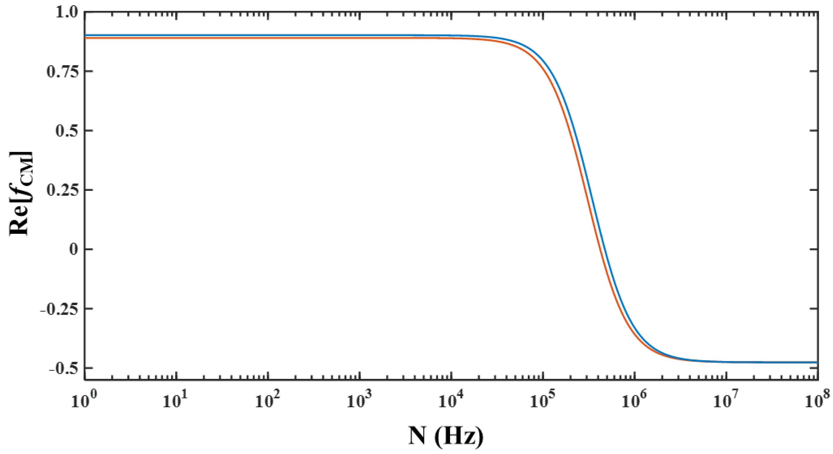
| Re[fCM] | Clausius–Mossotti factor (-) |
| r | radius (m or μm) |
| SE | separation efficiency |
| SP | separation purity |
| t | time (s) |
| U | velocity vector (m/s) |
| u | velocity along x-direction (m/s) |
| V | voltage (V) |
| W | width (m or μm) |
| w | electrode width (μm or m) |
| X | displacement vector (m or μm) |
| x | displacement in the x-direction (m) |
| y | displacement in the y-direction (m) |
| z | displacement in the z-direction (m) |
| co-ordinate in the x-direction | |
| co-ordinate in the y-direction | |
| co-ordinate in the z-direction | |
| Greek alphabet | |
| ε | permittivity (-) |
| εo | permittivity of free space (F/m) |
| σ | conductivity (S/m) |
| μ | viscosity (Pa∙s) |
| ρ | density (kg/m3) |
| ω | operating frequency (rad/s) |
| Subscripts | |
| 2 | 2-μm particle |
| 2.25 | 2.25-μm particle |
| bp | big microparticle |
| bulk | bulk electrical conductivity |
| ch | microchannel |
| cr | cross-over |
| DEP | dielectrophoresis |
| ext | external |
| e | entity |
| ext | external |
| f | focusing section |
| m | medium |
| o | outlet |
| RMS | root mean square |
| s | separation section |
| sp | small microparticle |
References
- Mathew, B.; Weiss, L. MEMS heat exchangers. In Materials and Failures in MEMS and NEMS; Tiwari, A., Raj, B., Eds.; Wiley: New York, NY, USA, 2015; pp. 63–120. [Google Scholar]
- Karsten, S.L.; Tarhan, M.C.; Kudo, L.C.; Dominique, C.; Fujita, H. Point-of-Care (POC) devices by means of advanced MEMS. Talanta 2015, 145, 55–59. [Google Scholar] [CrossRef] [Green Version]
- Plouffe, B.D.; Murthy, S.K. Perspective on microfluidic cell separation: A solved problem. Anal. Chem. 2014, 86, 11481–11488. [Google Scholar] [CrossRef] [Green Version]
- Gossett, D.R.; Weaver, W.M.; Mach, A.J.; Hur, S.C.; Tse, H.T.K.; Lee, W.; Amini, H.; Di Carlo, D. Label-free cell separation and sorting in microfluidic devices. Anal. Bioanal. Chem. 2010, 397, 3249–3267. [Google Scholar] [CrossRef] [PubMed] [Green Version]
- Alazzam, A.; Mathew, B.; Khashan, S. Microfluidic platforms for bio-applications. In Advanced Mechatronics and MEMS Devices II; Zhang, D., Wei, B., Eds.; Springer: Cham, Switzerland, 2017; pp. 253–282. [Google Scholar]
- Dash, S.; Mohanty, S. Dielectrophoretic separation of micron and submicron particles: A review. Electrophoresis 2014, 25, 2656–2672. [Google Scholar] [CrossRef] [PubMed]
- Kim, D.; Sonker, M.; Ros, A. Dielectrophoresis: From molecular to micrometer-scale analytes. Anal. Chem. 2019, 91, 277–295. [Google Scholar] [CrossRef] [PubMed]
- Alnaimat, F.; Ramesh, S.; Adams, S.; Parks, N.; Lewis, C.; Wallace, K.; Mathew, B. Model-based performance study of dielectrophoretic flow separator. IEEE Sens. Lett. 2019, 3, 1–4. [Google Scholar] [CrossRef]
- Weng, P.-Y.; Chen, I.-A.; Yeh, C.-K.; Chen, P.-Y.; Juang, J.-Y. Size-dependent dielectrophoretic crossover frequency of spherical particles. Biomicrofluidics 2016, 10, 011909. [Google Scholar] [CrossRef] [PubMed] [Green Version]
- Demierre, N.; Braschler, T.; Linderholm, P.; Seger, U.; van Lintel, H.; Renaud, P. Characterization and optimization of liquid electrodes for lateral dielectrophoresis. Lab Chip 2007, 7, 355–365. [Google Scholar] [CrossRef] [PubMed]
- Han, K.H.; Frazier, A.B. Lateral-driven continuous dielectrophoretic microseparators for blood cells suspended in a highly conducive medium. Lab Chip 2008, 8, 1079–1086. [Google Scholar] [CrossRef] [PubMed]
- Karlj, J.G.; Lis, M.T.W.; Schmidt, M.A.; Jensen, K.F. Continuous dielectrophoretic size-based particle sorting. Anal. Chem. 2006, 78, 5019–5025. [Google Scholar] [CrossRef] [PubMed]
- Wang, L.; Lu, J.; Marchenko, S.A.; Monuki, E.S.; Flanagan, L.A.; Lee, A.P. Dual frequency dielectrophoresis with interdigitated sidewall electrodes for microfluidic flow-through separation of beads and cells. Electrophoresis 2009, 30, 782–791. [Google Scholar] [CrossRef] [PubMed]
- Lewpiriyawong, N.; Yang, C.; Lam, Y.C. Continuous sorting and separation of microparticles by size using AC dielectrophoresis in a PDMS microfluidic device with 3-D conducting PDMS composite electrodes. Electrophoresis 2010, 31, 2622–2631. [Google Scholar] [CrossRef] [PubMed]
- Altinagac, E.; Kizil, H.; Trabzon, L. Biological particle manipulation: An example of Jurkat enrichment. Micro Nano Lett. 2015, 10, 550–553. [Google Scholar] [CrossRef]
- Ali, H.; Park, C.W. Numerical study on the complete blood cell sorting using particle tracing and dielectrophoresis in a microfluidic device. Korea-Aust. Rheol. J. 2016, 28, 327–339. [Google Scholar] [CrossRef]
- Alazzam, A.; Hilal-Alnaqbi, A.; Alnaimat, F.; Ramesh, S.; Al-Shibli, M.; Mathew, B. Dielectrophoresis based microfluidic devices for field flow fractionation. Med. Devices Sens. 2018, 1, e10007. [Google Scholar]
- Tajik, P.; Saidi, M.S.; Kashaninejad, N.; Nguyen, N.T. Simple, cost-effective, and continuous 3D dielectrophoretic microchip for concentration and separation of bioparticles. Ind. Eng. Chem. Res. 2019, 59, 3772–3783. [Google Scholar] [CrossRef]
- Alnaimat, F.; Ramesh, S.; Alazzam, A.; Hilal-Alnaqbi, A.; Waheed, W.; Mathew, B. Dielectrophoresis based 3D-focusing of microscale entities in microfluidic devices. Cytom. Part A 2018, 93, 811–821. [Google Scholar] [CrossRef] [PubMed] [Green Version]
- Mathew, B.; Alazzam, A.; Abutayeh, M.; Gawanmeh, A.; Khashan, S. Modeling the trajectory of microparticles subjected to dielectrophoresis in a microfluidic device for field flow fractionation. Chem. Eng. Sci. 2015, 138, 266–280. [Google Scholar] [CrossRef]
- Burden, R.L.; Faires, J.D. Numerial Analysis, 8th ed.; Brooks Cole: Boston, MA, USA, 2004. [Google Scholar]
- Catellanos, A.; Ramos, A.; Gonzales, A.; Green, N.G.; Morgan, H. Electrohydrodynamics and dielectrophoresis in microsystems: Scaling and laws. J. Phys. D Appl. Phys. 2003, 36, 2584–2596. [Google Scholar] [CrossRef]


© 2020 by the authors. Licensee MDPI, Basel, Switzerland. This article is an open access article distributed under the terms and conditions of the Creative Commons Attribution (CC BY) license (http://creativecommons.org/licenses/by/4.0/).
Share and Cite
Krishna, S.; Alnaimat, F.; Hilal-Alnaqbi, A.; Khashan, S.; Mathew, B. Dielectrophoretic Microfluidic Device for Separating Microparticles Based on Size with Sub-Micron Resolution. Micromachines 2020, 11, 653. https://doi.org/10.3390/mi11070653
Krishna S, Alnaimat F, Hilal-Alnaqbi A, Khashan S, Mathew B. Dielectrophoretic Microfluidic Device for Separating Microparticles Based on Size with Sub-Micron Resolution. Micromachines. 2020; 11(7):653. https://doi.org/10.3390/mi11070653
Chicago/Turabian StyleKrishna, Salini, Fadi Alnaimat, Ali Hilal-Alnaqbi, Saud Khashan, and Bobby Mathew. 2020. "Dielectrophoretic Microfluidic Device for Separating Microparticles Based on Size with Sub-Micron Resolution" Micromachines 11, no. 7: 653. https://doi.org/10.3390/mi11070653