


1. Introduction
More than 98% of Antarctica is covered by ice, and one of the most exciting investigations of our planet today concerns the exploration of Antarctic subglacial environments, as ‘another world’ exists beneath the ice sheet. This subglacial environment is of interest to a variety of natural and interdisciplinary science questions. Subglacial environments have become central to our understanding of the formation of Antarctic ice sheets (Jamieson and others, Reference Jamieson, Sugden and Hulton2010) and to assessments of possible future climate change (Bell, Reference Bell2008). Another exciting aspect of the subglacial environments (probably unique to the Antarctic) is the prospect of new forms of life inhabiting not only subglacial lakes but also subglacial till, vents or cracks in bedrock (Christner and others, Reference Christner, Skidmore, Priscu, Tranter, Foreman and Margesin2008; Gilichinsky and others, Reference Gilichinsky and Margesin2008). Subglacial environments play a key role in the dynamics of the overlying ice sheet (Bennett and Glasser, Reference Bennett and Glasser2009; Rignot and others, Reference Rignot, Mouginot and Scheuchl2011; Spector and others, Reference Spector2018). Additionally, bedrock samples provide significant information regarding subglacial geology and tectonics (Mikhalsky and others, Reference Mikhalsky, Kamenev and Mikhalskaya2010).
Geologically, the Antarctic is the least explored place in the world (Curtin and others, Reference Curtin, Hayes, Jakob, McClatchy and Schleich2004). Currently, the conditions beneath the ice are mainly investigated via indirect methods of geophysical remote sensing (Block and others, Reference Block, Bell and Studinger2009; Aitken and others, Reference Aitken2014; An and others, Reference An2017), and there is no single framework for interpreting these data. Direct observations made via drilling are complicated by extremely low temperatures at the surface of, and within, the Antarctic ice sheet, as well as by ice flow, the absence of roads and infrastructure, storms, winds and snowfalls. Nevertheless, borehole drilling is still considered as the only valid method to study the Antarctic subglacial environment.
To date, few studies have successfully recovered bedrock samples from beneath the Antarctic ice sheet (Fig. 1). The published data of subglacial drilling with final depths >50 m are limited to a 2.2 m-long bedrock core in the coastal area of Queen Mary Land near Mirny Station (Treshnikov, Reference Treshnikov1960); a short, 10 cm-long bedrock core beneath Taylor Dome (Steig and others, Reference Steig2000); an ~8 m-long bedrock core near the Pirrit Hills (Kuhl and Gibson, Reference Kuhl and Gibson2019); a short, 6 cm-long bedrock core at the flank of the Dålk Glacier near Chinese Zhongshan Station in the Larsemann Hills (Talalay and others, Reference Talalay2021); and a little over 2 m in length bedrock core at Minna Bluff (Goodge J and Severinghaus J, 2020, https://www.rapidaccessicedrill.org/we-did-it/). Bedrock cores have never been obtained from inland East Antarctica. Two types of subglacial drilling technologies have been used to recover subglacial bedrock samples (Talalay, Reference Talalay2013): (1) commercial drilling with conventional core barrels and wire-line core barrels and (2) electromechanical cable-suspended drilling with near-bottom fluid circulation. These drilling technologies have different conceptual bases, limits, performances and ranges of applicability.
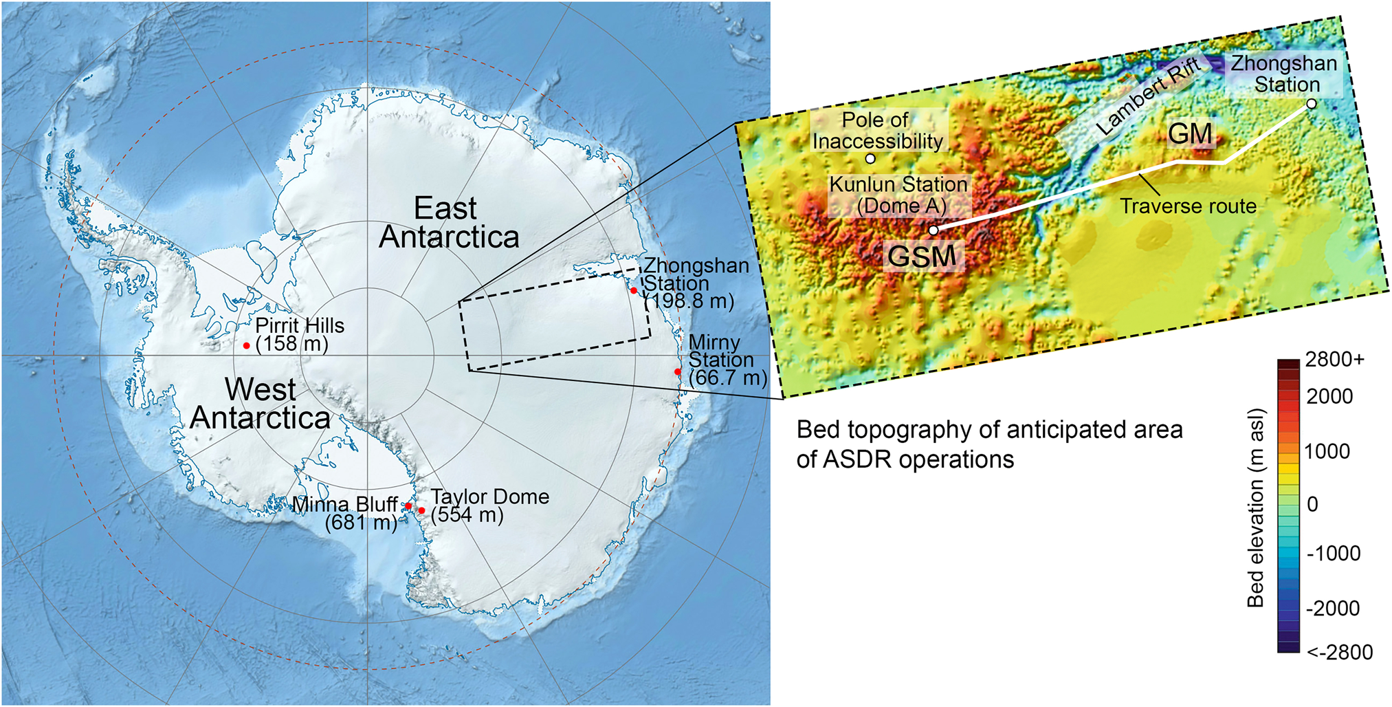
Fig. 1. Location of five boreholes in the Antarctic ice sheet, extending to the bedrock beneath it. The rectangular box indicates the anticipated area of operations for the ASDR drilling system; the inset map showing the bed topography is modified from Fretwell and others (Reference Fretwell2013); GSM, Gamburtsev Subglacial Mountains; GM, Grove Mountains.
For commercial drill rigs to be used in Antarctica, many components, such as the hydraulic system and fluid-processing system, must be redesigned, as they are not applicable at low temperatures. Commercial drill rigs operate as outdoor machines and can involve the use of lightweight and simple tents for drilling at remote locations supplied by airplanes (e.g. Kuhl and Gibson, Reference Kuhl and Gibson2019). However, pitching up the tent and arrangement of heavy drilling equipment in the tent take much time. In addition, in some locations, tents and primitive shelters are inadequate under extremely low temperatures and storm winds in Antarctica. Continuous circulation of the drilling fluid in the borehole can cause loss of circulation due to leakage through the casing and hydraulic fracturing of the ice massif. Additionally, commercial drill rigs are heavy, consume large amounts of power and are logistically difficult to move and support; thus, their use in Antarctica is not only disadvantageous but, in some cases, impossible.
In our opinion, electromechanical cable-suspended drilling is a more effective method for penetrating subglacial bedrock. The main feature of electromechanical cable-suspended drilling is that an armored cable with a winch is used to provide power to the down-hole motor system and retrieve the down-hole unit. The use of an armored cable permits a significant reduction in power and material consumption, a reduction in the time required for round-trip operations and simplification of the process of cleaning the hole of cuttings. Near-bottom circulation of the drilling fluid is safer and simpler than continuous circulation used by commercial drill rigs. However, electromechanical drilling has less bedrock drilling capacity that can be critical when determining true bedrock vs an isolated rock.
To drill through ice and bedrock, the Antarctic subglacial drilling rig (ASDR), which features a new, modified version of the cable-suspended Ice and Bedrock Electromechanical Drill (IBED), was developed at Jilin University (Talalay and others, Reference Talalay, Siegert, Jamieson and White2017). The remainder of this paper describes the drilling target, conditions and requirements, as well as the general concept of the drilling system. Three related papers describe the IBED drill (Talalay and others, Reference Talalay2021), auxiliaries (Fan and others, Reference Fan2021) and control system (Zhang and others, Reference Zhang2021).
2. Drilling Target and Conditions
The ASDR is intended to recover ice and bedrock core samples that provide the scientific community a unique opportunity to study the interface between the ice sheet and the underlying solid earth and to perform mineralogical, crystallographic and petrographic analyses of the bedrock (Goodge and Severinghaus, Reference Goodge and Severinghaus2016). The bedrock samples can be dated via radioactive isotope methods (40K, 230Th, 234U, 238U). It is also considered important to measure the 10Be radioactive isotope in the bedrock (Spector and others, Reference Spector2018). This form of the element, which is due to the reaction of cosmic rays with nitrogen and oxygen atoms, decays at a steady rate. Thus, measuring how much of the isotope is currently present in the bedrock can reveal when the rocks were last uncovered by ice and exposed to the atmosphere, providing another window into the Antarctic climatic past. Finally, pore ice or ‘cement’ ice of frozen bedrock is potentially more informative and a more significant microbial repository than the superincumbent ice sheet (Gilichinsky and others, Reference Gilichinsky2007).
The anticipated area of operations for the ASDR lies in the central and eastern part of East Antarctica, between Zhongshan Station at the coast and Kunlun Station at the highest point of the Antarctic Plateau focusing in the area of the Gamburtsev Subglacial Mountains (GSM) (see the rectangular box in Fig. 1). The GSM have become the subject of great scientific interest because the mechanism driving the uplift of the range, which resembles younger mountain ranges in shape, in the middle of the old Antarctic Plate is unknown (Ferraccioli and others, Reference Ferraccioli2011). The GSM are at least 750 km long and 250 km wide. The mean elevation of the range is 1351 m a.s.l., with the highest mountain peaks over 2700 m (Creyts and others, Reference Creyts2014).
The surface topography above the GSM consists of offset steps to the northwest, in the direction of Lambert Glacier (Herzfeld, Reference Herzfeld2004). The average surface elevation is 3600–3900 m. However, at the highest point (Dome A), the elevation reaches 4091.2 m (Cheng and others, Reference Cheng, Gong, Zhang, Sun and Wei2009). The surface ice velocities above the GSM are low because of the extensive areas of cold-based ice (Llubes and others, Reference Llubes, Lanseau and Rémy2006). The mean ice velocity over Dome A is only 0.11 m a−1 (Yang and others, Reference Yang2014); however, the velocity is higher toward Lambert Glacier, with the maximum velocity reaching ~20 m a−1 at the flank of the GSM (Rignot and others, Reference Rignot, Mouginot and Scheuchl2011).
The ice thicknesses vary between 1000 and 3000 m across the high peaks and deep valleys. At its thinnest, ice is <600 m thick above some peaks, but it reaches >4500 m in depth on the northern flank of the mountains, where the GSM meets the Lambert Rift, at the head of the Lambert Glacier. The mountains are divided by a series of valleys that resemble a fluvial drainage system. The valleys are typically 20–25 km wide and 100–200 km long. However, the two largest valleys in the center of the mountain range are >350 km long.
Another interesting feature in this region is the Grove Mountains (GM), which are located on the right coast of the Lambert Rift, 450 km to the south of the Zhongshan Station (Liu and others, Reference Liu, Zhao, Liu and Yu2003). The GM expose a group of isolated nunataks, but many aspects of the subglacial range geology are still not fully understood.
The central part of East Antarctica is the coldest place on Earth. The mean annual temperature in this area is −53°C (King and Turner, Reference King and Turner1997; Creyts and others, Reference Creyts2014). The 10 m firn temperature at Dome A was −58.3 and −58.2°C in 2005 and 2006, respectively; the minimum recorded temperature was −82.3°C (on 27 July 2005) (Xiao and others, Reference Xiao2008). The ice-sheet surface in the interior of Antarctica never melts, even in the summer, and the snowpack remains dry.
It is expected that the ice-firn transition in this area occurs at depths of 90–100 m, similar to that found at Dome A (Hou and others, Reference Hou, Li, Xiao, Pang and Xu2009). In areas closer to the coast, the ice-firn transition is shallower (60–70 m). A zone of extremely fragile ice, i.e. ‘brittle’ ice, has been observed at all of the deep drilling sites on the Antarctic ice sheet, beginning several hundreds of meters below the ice surface and extending to depths of 1000–1500 m (Neff, Reference Neff2014). The poor ice-core quality in the brittle ice zone remains a technical challenge at all phases of ice-core studies. The interval of the brittle zone varies from site to site; however, the brittle zone starts at Dome A at a depth of ~600 m, which can be used as a reference for planning future drilling operations in this area.
A debris-containing basal ice zone may lodge beneath a glacier when the frictional resistance between it and the bed exceeds that of the ice above, which shears over the debris-containing ice mass (Bennett and Glasser, Reference Bennett and Glasser2009). It may have a height of up to tens of meters. A debris-containing ice zone differs from the overlying ice with regard to not only its debris content but also its structure, properties and composition of solutes and gases. In general, debris-containing basal ice sequences have an anisotropic structure, consisting of individual layers, lenses and pods of different sizes. Typically, debris particles have sizes similar to that of silt and sand, with some particles up to a few centimeters in diameter. The dirt content varies from hundredths of a percent to several percent by weight.
It is important to set the drilling site in an area with dry, frozen-bed conditions in order to avoid contaminating the subglacial hydrologic environment. Herterich (Reference Herterich1988) was the first who predicted that ice in the GSM region is frozen to the bedrock. According to the modeling performed by Van Liefferinge and Pattyn (Reference Van Liefferinge and Pattyn2013), the mean basal ice temperature in most of the GSM area is below −10°C. On the upstream side of ridges, water collects in valley heads, forming large, continuous bodies, as indicated by numerous bright radar reflections (Creyts and others, Reference Creyts2014). No water is found via radar sounding along the network branches downstream of high ridges if the ice thickness above the bedrock is smaller than ~1950 m. The conduction is inversely proportional to the ice thickness; thus, the peaks and ridges under thin ice are below the freezing point, whereas the deep valleys are at the melting point.
The presence of frozen till beneath ice along the ridges is unlikely. We expect that the upper part (0.5–2 m) of the subglacial massif comprises frozen soil or metamorphic rock overlying the true bedrock, as was discovered in Arctic boreholes (Gow and Meese, Reference Gow and Meese1996; Vasiliev and Talalay, Reference Vasiliev and Talalay2010). Assuming that the thermal gradient is in the range of 3–4°C 100 m−1, which was observed in boreholes at the McMurdo Valleys (Pruss and others, Reference Pruss, Decker and Smithson1974), the permafrost thickness in the GSM ridges can be estimated as 350–500 m. As the GSM have been shielded from erosion since the latest Eocene Epoch, there are no prerequisites for the development of cryogenic textures in the bedrock, and the ice content is expected to be low (<1%). Supposedly, the GSM mainly comprise different types of gneisses and quartzites (personal communication from German Leitchenkov, 2016). The GM mainly consist of a series of high-grade metamorphic rocks, including felsic granulite, granitic gneiss, mafic granulite lenses and charnockite (Liu and others, Reference Liu, Zhao, Liu and Yu2003).
3. Requirements and Transportation
According to scientific interests, the following key operational requirements were set: (1) to drill the borehole through glacial ice to a maximal depth of 1400 m; (2) to drill into bedrock to a depth of at least 2 m and obtain core samples >35–40 mm in diameter; (3) to obtain a clean borehole that remains open for caliper-logging, temperature measurements and other downhole observations.
Antarctica is the most logistically challenging location on Earth. Polar operations depend heavily on transportation and support for personnel and equipment. Weight and cargo size are among the most significant problems for the transportation of drilling equipment. Typically, drilling equipment is transported to Antarctica via ships. Most coastal stations have offshore anchorages, and cargo is transferred from ship to shore by small boats, barges, helicopters or vehicles over the sea ice. Then, the equipment is transported to the site by air, using airplanes and helicopters, or by surface traverses.
The polar terrain, climate and material availability require the use of aircrafts that are fitted with skis and able to land/take off on/from airfields that are unprepared or semi-prepared for snow. The useful payload and maximum range of the most commonly used airplanes in Antarctica, Twin Otter and Basler BT-67, are 975 kg over 1344 km and 3450 kg over 1760 km, respectively. Maximum payload of multirole helicopter KA-32 frequently used in Antarctica is 3700 kg in transport cabin and 5000 kg on external sling with a maximum flight range of 650 km. All these are far less than weights of modern drilling rigs. In addition, bulky drilling equipment can be bigger in size than aircraft cargo doors (e.g. cabin door of Twin Otter has a size of 1.27 m × 1.42 m only).
Therefore, surface traverses have been (and still are) a major component of Antarctic exploration for re-supply and drilling-related purposes. During past decades, several movable drilling rigs were designed by Russian, Australian, French and American drilling engineers; some of them are shown in Figure 2.
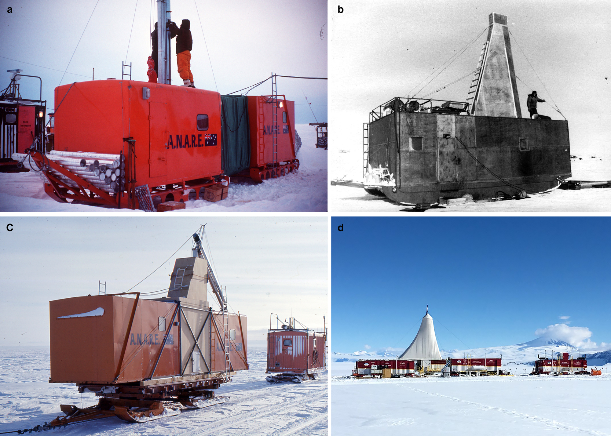
Fig. 2. Movable drilling rigs in Antarctica: (a) setting up the drill van of the Australian National Antarctic Research Expedition with ice-core containers on the tow bar, Law Dome, May 1977 (Photo D. Robinson from Talalay, Reference Talalay2020); (b) movable drilling shelter PBU-2 of Leningrad Mining Institute towed to Vostok Station in the summer season of 25th Soviet Antarctic Expedition, 1980 (Vasiliev and others, Reference Vasiliev2007); (c) movable drill van mounted on an Otago sled of the Australian National Antarctic Research Expedition, October 1977 (Photo: J. Wilson from Talalay, Reference Talalay2020); (d) field deployment of US Rapid Access Ice Drill modules on sleds, Minna Bluff, December 2017 (posted by J. Goodge on 25 December 2017 at http://www.rapidaccessicedrill.org/drilling-with-raid/).
Currently, the two best-performing categories of vehicles are the Caterpillar Challenger and the Kassbohrer PistenBully (PB) series. The Caterpillar Challenger has a low ground pressure (30 kPa), a powerful engine (215–230 kW) and a simple and robust design. The Challengers have a maximum speed (with no load) of 30 km h−1 and an operational cruising speed of 6–15 km h−1 when towing loads. The Kassbohrer PB-330 tractors are powerful (240 kW) and light enough to travel up steep slopes. The ground pressure of the PB-330 is extremely low (6 kPa), and the maximum speed is ~21 km h−1 with no load. The operational cruising speed of the PB-330 varies from 8.5 to 19 km h−1 depending on loads. The Kassbohrer PB-330 can tow sledges weighing 30–35 tons, and the Caterpillar Challenger has a towing capacity of 70–75 tons.
It was suggested to use traversal resources of the Chinese National Antarctic Research Expedition (CHINARE) located at Zhongshan Station. This station serves as the base to transport materials and personnel to inland Kunlun Station at Dome A, which is ~1200 km from Zhongshan Station. The ASDR and accessories are transported to the chosen site using three Kassbohrer PB-330 vehicles (Fig. 3). The proposed snow train includes a movable drilling shelter (25 tons), a workshop (23 tons), living shelter (8 tons), a sledge tank with fuel (16 tons), a sledge with drilling fluid drums (16 tons) and a sledge with accessory equipment (10 tons). The equipment would be ready for drilling operations 2–3 d after arrival at the chosen site.
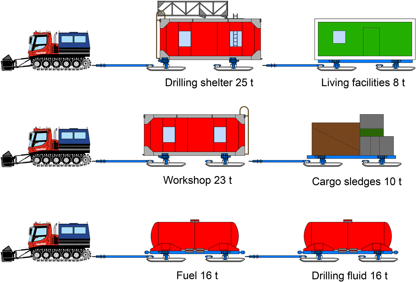
Fig. 3. Proposed traversal structure with the ASDR system.
To design the ASDR, the following environmental conditions and requirements were set: (1) minimal ambient temperatures (during the summer season) of −40°C; (2) maximal wind speed of 20–25 m s−1; (3) density of the snow cover of 150–250 kg m−3; (4) maximal ground pressure of 3.5 kPa; (5) crossing ability of zastrugi, which are usually 0.4–0.6 m high, sometimes up to 1.5 m; (6) rated speed of the snow train of 10–15 m h−1. Drilling operations will be performed around-the-clock on a three-shift basis, with two drilling operators in each shift. The core production in the glacial ice is expected to be no less than 20–25 m d−1. The ASDR is wintered at Zhongshan Station, and it will launch from there each season for traversal. When necessary, the main components of the ASDR can be left at the drilling site during winter.
4. General Concept of ASDR
The drilling facilities are divided into two groups: those associated with the movable drilling shelter and those associated with the movable workshop (Fig. 4). The drilling shelter and workshop are connected by a steel pathway with an adjustable length of 2–3 m. All of the materials used are non-flammable. To facilitate helicopter unloading of the research vessel, the shelter and workshop can be disassembled, with individual parts weighing <2–3 tons. The whole ASDR system weighs ~55 tons, including the transport packaging.
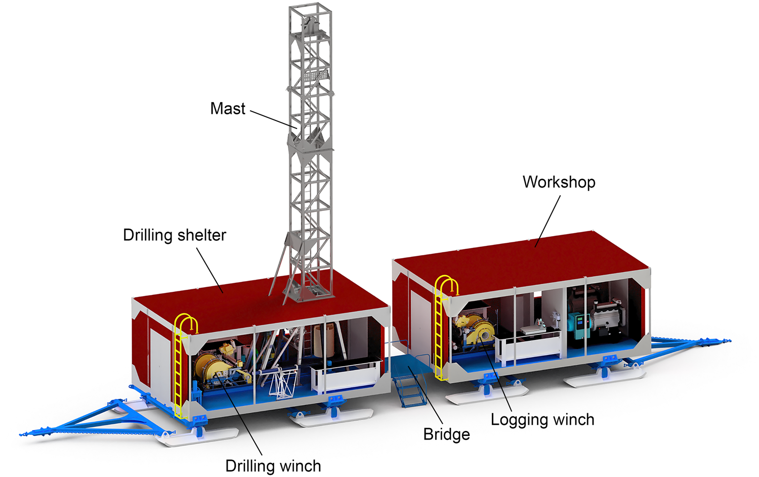
Fig. 4. Three-dimensional schematic of the movable drilling shelter and the workshop connected by the bridge; the siding in the foreground and in the mast is not shown, for better visibility.
The drilling shelter (without the sledges, towbar and mast) has overall dimensions of 7.8 × 4.8 × 3.0 m. The wall, roof and floor are composed of sandwich panels with outer steel plates with a thickness of 1 mm and an inner thermal insulator (foam polyurethane with a density of 40–60 kg m−3). The total thickness of the wall and roof panels is 150 mm. The roof and floor are reinforced by steel beams. Additionally, the floor is covered by corrugated steel plates. The shelter has four windows (0.96 × 1.2 m) made of automotive triplex glass and two gates (1.5 × 2.2 m) with two doors on each of the short sides. The total weight of the drilling shelter – including the mast, ski sledge, drilling winch and other equipment – is ~25 tons.
4.1. Sled
To minimize the towing resistance for a given payload weight and snow strength, it is necessary to minimize the sliding friction of the sled and the ground pressure and to maximize the snow contact length. The CHINARE steel sled was used as a prototype of the ASDR sled, with modifications (Table 1). To account for a heavier payload, the snow contact area of the sled was increased from 5.3 to 8.0 m2. To pass through zastrugi fields with a larger sled base, the ride height (distance between the lowest point of the sled frame and a flat snow surface) was increased from 300 to 355 mm.
Table 1. Sled parameters
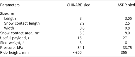
The sled consists of two transverse frames with four 3.05 × 0.8 m skis (Fig. 5). In an idealized static case, the shelter exerts a pressure no higher than 34 kPa on the snow, which is sufficiently low compared with the pressure of a human foot, which can be 50–60 kPa. During movement, each individual ski can swing in a vertical plane, and the ski pair can be turned in a horizontal plane, allowing easier passage over zastrugi fields. The front and back skis are connected by intercrossed chains for turning synchronization. To reduce the friction, the bottom surface of the skis is covered by 8 mm-thick Nylon plates.

Fig. 5. ASDR sled (all sizes are given in mm).
4.2. Leveling jacks
Four-hand screw jacks with an extension stroke of 300 mm are located at the corners of the shelter (Fig. 6). During transportation, the floor of the shelter is bolted to the transverse frames. At the drill site, the drilling shelter is located on a firm, level base prepared by the snow vehicle blade, the bolts are released, and the shelter floor is leveled so that the drill suspended on the cable is aligned with the axis of the borehole mouth. The drilling shelter remains on the transverse frames of the sledge during drilling operations.
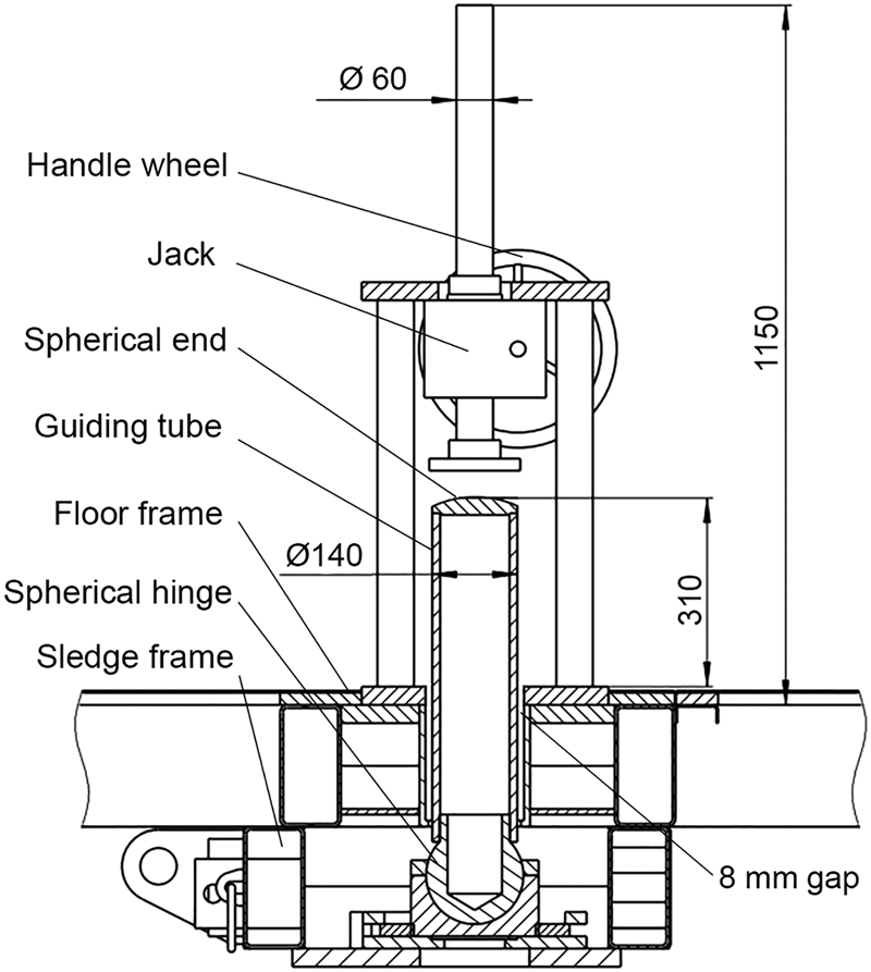
Fig. 6. Schematic of the leveling jack; four of them are located at the corners of the shelter (all sizes are given in mm).
Several leveling methods were considered to prevent the four screws from locking each other in the leveling process of the drilling shelter. Finally, a simple method was selected, as follows: (1) an 8 mm gap is maintained between the guiding tube and the floor frame, (2) the bottom part of the guiding tube is fixed with a spherical hinge, (3) the top of the guiding tube has a spherical end. Thus, during leveling, only a small relative displacement (<8 mm) can occur between the floor and the guiding tube, and the drilling shelter can be leveled within 300 mm without jamming. The rated load of each leveling jack is 100 kN. The maximum input torque is 20 N⋅m, which can easily be produced by hand with a 400 mm-diameter handle wheel.
4.3. Mast
The total height of the mast (from the floor of the shelter) is 13.5 m. The mast has a square 1.0 × 1.0 m cross-section, and the operator can climb to the top using a stairway fixed to the inner wall of the mast. The mast consists of two parts (5.4 and 5.1 m), allowing it to be folded during transportation (Fig. 7). Upon arrival at the drilling site, the mast is unfolded in the horizontal plane and then erected in a vertical position by a mechanical screw. The mechanical screw is driven by an electric 380 V 2.2 kW motor.

Fig. 7. Schematic of mast erecting (siding on the mast is not shown).
The maximum length of the screw is 2.02 m, and the diameter is 80 mm. After being erected, the mast is rigidly fixed to the roof, and during drilling, it is supported by four legs made of 100 × 100 mm square tubes and four guy-wire lines connected to the corners of the roof. The total time required to erect the mast is ~1 h.
4.4. Movable workshop
The workshop has the same basic design and dimensions as the drilling shelter but does not include the mast or hand screw jacks for floor leveling. It is divided into two rooms: one for generators and one that serves as a logging/glaciological laboratory and workshop. Electrical sockets are installed on the walls of the drilling shelter and the workshop to provide power. The movable drilling shelter and workshop were designed in cooperation with and produced by Cortech Drilling Equipment Co. Ltd. in Beijing.
5. Computer Simulation of ASDR Components
To check the critical parts of the shelter design, such as the bolted joints of the frame, the Autodesk Inventor Stress Analysis was used (Fig. 8). It was assumed that the maximum axial load on the frame is 150 kN and that all the load is distributed on 48 × M24 bolted-type connections (3.125 kN for each connection). The bolt connections were checked for tensile strength, shear load, thread deformation and fatigue and had a safety factor of >2.
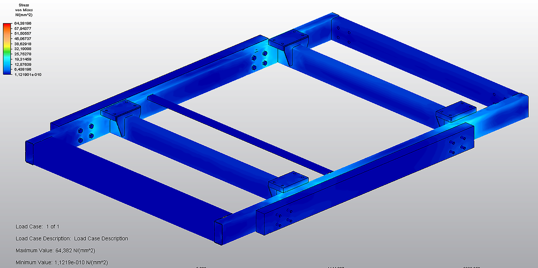
Fig. 8. Simulation results for the stress of the shelter base under the loads of the mast, walls and roof.
The shelter walls were checked for deformation under the loads of the mast and wind. During transportation, the 2.3-ton horizontally folded mast is placed on the model of the drilling shelter roof. Considering the safety factor of 2, a 45 kN vertical load was applied to the walls. In the simulation results (Fig. 9), the maximum stress was 2.03 × 10⁷ Pa, which was lower than the yield strength (2.35 × 10⁸ Pa), and the maximum deformation was 0.235 mm.
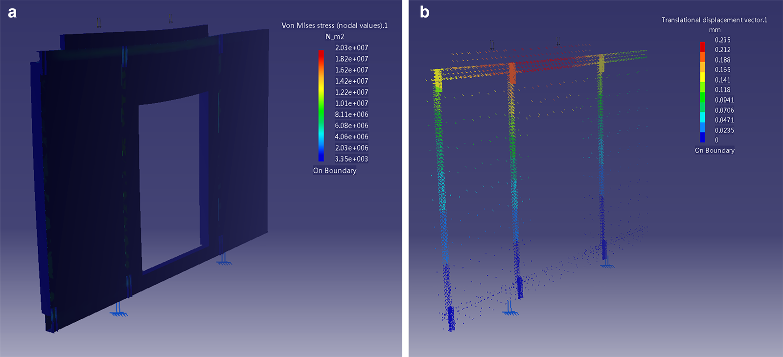
Fig. 9. Simulation results for the (a) stress and (b) deformation of the shelter walls under the load of the mast (2.3 tons), with a safety factor of 2.
Antarctica is one of the windiest places on Earth. Sustained winds of 70–90 m s−1 have been recorded on the continent (Gritzner, Reference Gritzner2007). It is expected that maximum winds of 25 m s−1 can occur in the anticipated area of operations for the ASDR drilling system. The wind pressure w p [kN m−2] can be calculated as follows:

where r is the air gravity (kN m−3), and v is the wind speed (m s−1).
Assuming that r = 0.01225 kN m−3 (under normal atmospheric conditions) and g = 9.83 m s−2 (at a latitude of 70°), we obtain

The maximum wind load is

where S w is the wall area (m2).
The most dangerous situation occurs when the longer side of the drilling shelter (S w = 23.4 m2) is perpendicular to the wind load. To examine the deformation of the shelter wall under storm winds (25 m s−1), 45 kN uniform load was applied to the side wall. A safety factor of 5 was used to account for gusts of wind that induce fluctuating forces on the structure and large dynamic motion. In the simulation results (Fig. 10), the maximum stress occurred at the connection between the walls and the floor, but it was significantly lower than the allowed yield strength.
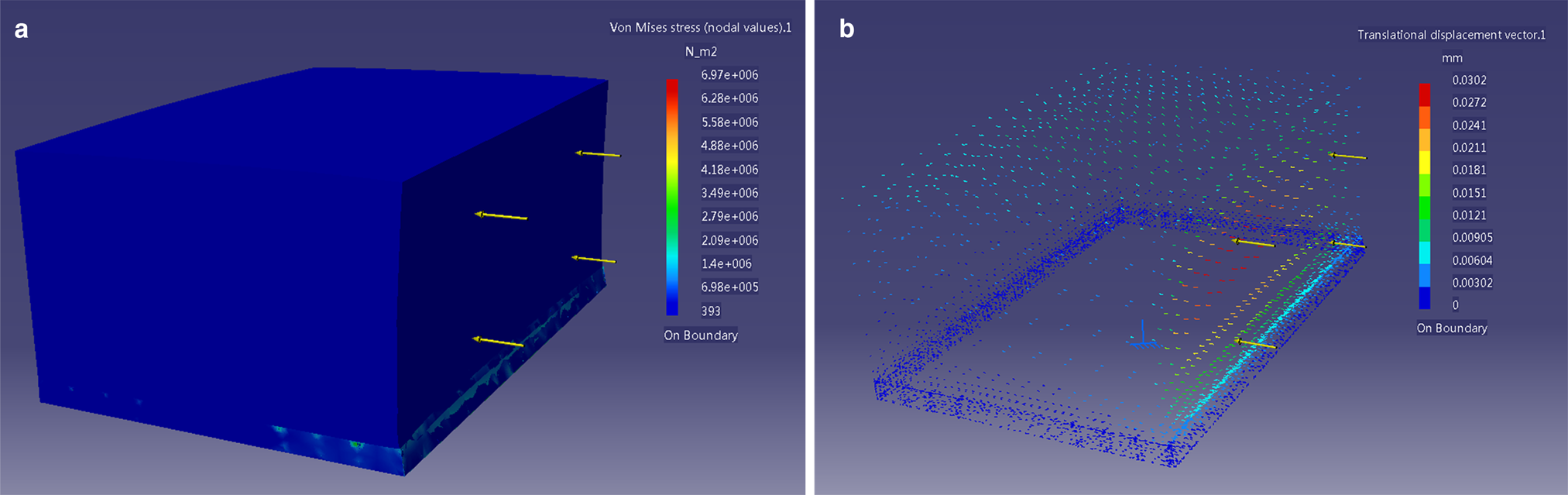
Fig. 10. Simulation results for the (a) stress and (b) deformation of shelter walls under the load of storm winds (25 m s−1) with a safety factor of 5.
6. Stability Under Wind Load
Wind is a powerful force that can significantly affect the stability of the drilling structure. If the moment produced by gravity is greater than the overturning moment produced by the wind load, the drilling shelter is safe:

where M 1 and M 2 are the overturning moments produced by wind acting on the mast and the side wall, respectively (N⋅m), and M 3 is the moment produced by the gravity of the drilling shelter (N⋅m).
These moments can be estimated according to Figure 11:


where F 1 and F 2 are the forces produced by wind acting on the mast and side wall, respectively (N); S m is the area of the mast side (m2); G is the gravitational force of the drilling shelter (N); and l 1, l 2 and l 3 are the force arms (m).
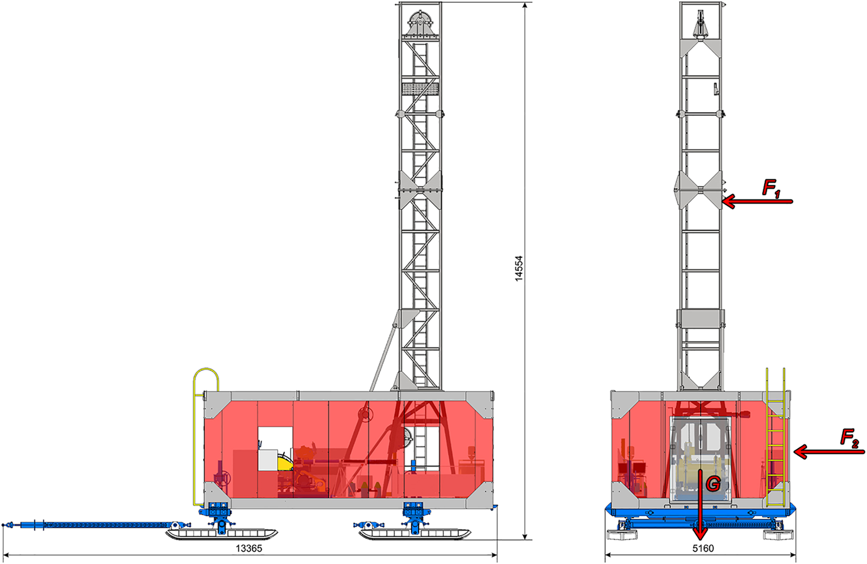
Fig. 11. Force diagram of the drilling shelter (siding on the mast is not shown) under a wind load (all sizes are given in mm).
According to the structure of the drilling shelter, l 1 = 9 m, l 2 = 2 m, l 3 = 2.4 m, S m = 12.6 m2 and G = 250 kN. Assuming that v = 25 m s−1, we obtain

Thus, the drilling shelter remains stable even when the wind speed exceeds 25 m s−1.
7. Assembly and Field Trials
The packed drill rig was transported to Antarctica by the Chinese research vehicle Xuelong and then lifted on an external sling by a KA-32 helicopter to Zhongshan Station. The weight of each airlifted piece was 2–3 tons, except for the drilling and logging winches, which weighed ~4 tons (winches can be dissembled into two parts, but to save time, they were transported as one piece).
In December 2018, the ASDR components were transported from the station to the ‘Starting Point’ site (the site serves for preparing the convoys to Dome A) at the edge of the ice sheet on transport sleds via sea-ice traversal (the route length was ~40 km). The movable drilling shelter and workshop were assembled by a five-person crew over 4 weeks (Fig. 12). The heavy components were lifted by a Caterpillar Challenger equipped with a crane having a maximal working height of 16 m and a load capacity of 6.5 tons. Preliminary tests were performed with mast lifting, leveling of the drilling shelter via hand screw jacks and a control system. Then, the ASDR was transported to the test-drilling site. Visual observations of the walls, roofs and inner auxiliaries indicated that all components were in good condition during and after the transportation. At the test site, 2-week drilling operations resulted in a borehole that reached the bedrock at a depth of 198 m (Talalay and others, Reference Talalay2021).

Fig. 12. ASDR assembly and transportation to the drilling site in the vicinity of Zhongshan Station, December 2018–January 2019.
8. Discussion and Conclusions
A new ASDR for use on the Antarctic ice sheet was designed, manufactured and tested. Our goal is to drill through the ice (drilling penetration depth of up to 1400 m), ice-sheet bed interface and bedrock substrate below. The ASDR can also be used for ice coring at the sites of special scientific interest. One of the nearest potential drilling sites is located ~10 km south (inland) of the recent site. At the new site, the ice sheet is thicker (600–800 m instead of 200 m). It is reasonable to test the ASDR on thicker ice and to attempt to obtain a long bedrock core before traveling to the Antarctic inland. Another practical reason for testing at this site is that it is located in the potential area of the new CHINARE runway construction, and logging in the borehole will help to monitor the ice dynamics and crevasse formation.
In future investigations, we will identify potential sites for subglacial drilling in the northern part of the GSM and in the ice-covered areas of the GM, as well as for ice-core profiling, including five to six 1000 m-deep ice boreholes between Zhongshan Station and Dome A, to study the dynamics of the Antarctic ice sheet. The proposed technology will provide a critical first look at the interface between the Antarctic ice sheet and the bedrock and allow researchers to perform in situ measurements and obtain samples of ice, glacial bed and rock for interdisciplinary studies in geology, glaciology, paleoclimatology and microbiology. The first step of the ASDR field tests has succeeded, and drilling at other sites is planned as soon as full financial and logistical support is obtained for the projects.
Acknowledgements
This research was supported by the National Science Foundation of China (project No. 41327804) and the Program for Jilin University Science and Technology Innovative Research Team (Project No. 2017TD-24). We are grateful to our research team members for their help with the ASDR design and testing. We thank the engineers and other employees of Cortech Drilling Equipment Co. Ltd. in Beijing for high-quality manufacturing of the ASDR and CHINARE for the logistical and financial support of field operations in Antarctica. We also thank Scientific Editor K. Slawny (US Ice Drilling Program) and two anonymous reviewers for fruitful suggestions, useful comments and editing.


 Open access