


Introduction
The Antarctic subglacial drilling rig (ASDR) is designed to recover 105 mm-diameter ice cores from depths of 1400 m and 41.5 mm-diameter bedrock cores from depths of 2 m (Talalay and others, Reference Talalay, Siegert, Jamieson and White2017; Talalay and others, Reference Talalay2021a). Keeping in mind the shortcomings of conventional deep core-drilling technology, such as long construction periods and multi-year drilling sites, the ASDR uses a movable working shelter design, which can be ready for drilling operations in 2–3 d after arrival at the chosen site. This substantially shortens the on-site preparation time. Drilling operations can be carried out around the clock on a three-shift basis, with two drilling operators working during each shift. Firn–ice–bedrock core drilling is carried out with an ice and bedrock electromechanical drill (IBED) after rigging up the ASDR (Talalay and others, Reference Talalay2021b). A typical sequence of drilling operations is shown in Figure 1.
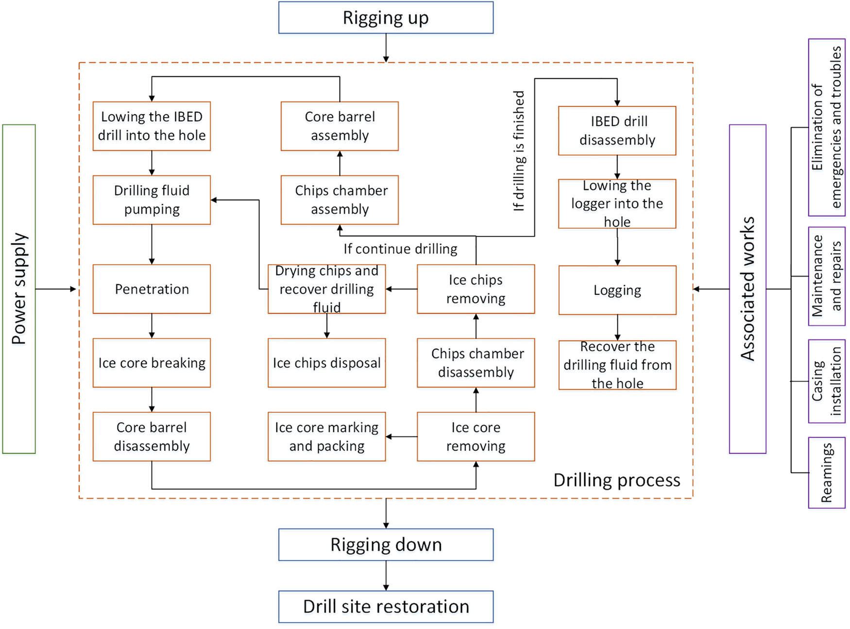
Fig. 1. Schematic of the drilling process including penetration, tripping, surface servicing, power supply and other associated works.
The IBED is lowered to the bottom of the borehole under the action of gravity using a winch and cable. This technique is highly energy efficient and simple, but the time for lowering depends on the hydrodynamic processes corresponding to drill movement in the borehole. The free-fall speed of the drill is limited by a piston effect when the borehole wall forms a space constraint between the drill and borehole. The lowering speed, which is expected to be in the range of 0.5–1 m s−1, depends mainly on the size of the annular gap and viscosity of the drilling fluid. In general, the cable-lowering speed should be equal to the free speed of drill in the fluid, which may vary due to variations in drilling fluid viscosity and borehole irregularities. If this is not ensured, the armor of the electromechanical cable slackens, birdcages and kinks develop, and the electrical core can be damaged (Talalay and others, Reference Тalalay2015). The best way to avoid such problems is to carefully maintain cable tension when it is lowered into the borehole. This tension is achieved using a manual winch control while following the readings of a cutter load sensor installed in the drill.
While lowering the drill, the level of drilling fluid is checked after every run and new fluid is pumped into the borehole if the fluid level is lower than the minimum permitted level. Fluid level in deep boreholes should be kept no deeper than 70–80 m from the surface or else problems related to borehole closure may occur (Talalay and others, Reference Talalay2104). In shallow boreholes, fluid can fill only the near-bottom part of the borehole and helps in sweeping chips away from the drill head.
The driving unit of the drill is powered when the drill arrives at a distance of 0.5–1.0 m from the bottom of the borehole, and when it touches the bottom, the drill head starts to penetrate. To limit and control cutting depth during drilling in ice as well as the pitch and rate of penetration, shoes are installed on the open side of the drill head. Shoe clearance is regulated using shims installed between the shoe and drill head body (Talalay, Reference Talalay2014b).
The IBED uses a bottom circulation system with a downhole pump and chip chamber for filtering the fluid and collecting cuttings. A drill motor runs the pump and turns the core barrel assembly. Fluid flows from the pump into the space between the drill and borehole wall to the bottom of the drill; while passing through openings in the drill head, the fluid picks up chips and flows upwards between the core and inner surface of the core barrel. This fluid, which contains cuttings, then passes through a cylindrical Johnson-type screen in the chip chamber. From the chip chamber, pure fluid is directed back to the pump.
When penetration is finished, the winch provides a tension of 5–10 kN for breaking the ice core and 15–20 kN for breaking the bedrock core; subsequently, the drill is lifted to the surface. Lifting speed is determined by the gap between the drill and borehole wall, viscosity of the drilling fluid and mainly the power of the winch motor. Lifting speed is controlled by the maximum absorbed current of the winch motor and is limited by safety rules (according to prospecting drilling safety rules, the maximal permissible tripping speed of a drill is 1.0 m s−1). We expect that the lifting speed range would be the same as that for lowering, i.e. 0.5–1 m s−1.
When the drill reaches the surface, the core barrel needs to be disassembled by the pipe handler and core is removed from the barrel for logging and packing. Next, the chip chamber is drawn out and installed on the vibrator table to remove chips. The collected ice chips are put into a centrifuge for drying and the recovered drilling fluid is directly dumped into the borehole. Later, after assembling the chip chamber and core barrel with the drill, the next run is carried out. The drilling process is repeated until the target depth is reached.
When drilling is completed, a logger is lowered into the borehole using a logging winch to measure the temperature, pressure, diameter and inclination of the borehole. The plan is to recover drilling fluid from the borehole to reduce environmental impact. Other associated works such as reaming, casing installation, maintenance and repairs, and emergency handling can be carried out during drilling as and when required. Rigging down the drill rig and drill site restoration will be conducted when the drilling project is completely finished. At the end of this process, the ASDR is moved to the next drilling site.
To ensure safety and convenient drilling with ASDR, special drilling auxiliaries are needed to accomplish drilling tasks and surface servicing. At the same time, appropriate environmental measures should be taken to reduce environmental impact. Most of the auxiliary equipment is installed inside the movable drilling shelter and movable workshop. ASDR monitoring and control systems are described in a separate study (Zhang and others, Reference Zhang2021).
2. Main concept
Depending on their function, drilling auxiliaries are classified as the power supply system, drill lifting system, pipe handler, ice core processing system, ice-chip processing system, maintenance and repair system, and environmental measures. The arrangement of auxiliaries in the drilling shelter and workshop is shown in Figure 2.

Fig. 2. Arrangement of auxiliaries in the drilling shelter and workshop (modified from Talalay and others, Reference Talalay, Siegert, Jamieson and White2017).
The power supply system provides electric power to equipment used for site construction, drilling and life support. Two generators are installed in a separate room in the movable workshop. Power is supplied by one of the generators while the other serves as a spare. An automatic control system ensures uninterrupted power supply by switching on the spare generator within 5 s of failure of the running generator. Thus, drilling accidents associated with disruption in power supply can be avoided.
The drill lifting system is mainly employed to hoist the drill and loggers. It consists of a drilling winch, logging winch and armored cables. The drill winching system should meet a speed requirement of up to 1 m s−1 for tripping and 20 m h−1 for IBED penetration, provide power supply to downhole units and transmit signals from the drill. The logging winching system provides only tripping with a speed of up to 1 m s−1 and transmits signals from loggers.
The pipe handler was designed to assist drillers in clamping and screwing drill components, especially with the ice core barrel that needs to be assembled/disassembled after every run. According to the structural design of IBED and the movable drilling shelter, the drill should be serviced vertically. In the field, a pipe handler can greatly reduce labor intensity related to drilling; it consists of a fixed clamp and a screwing/unscrewing trolley. The clamp is installed inside the mast of the movable drilling shelter for clamping and fixing the upper part of the drill. The screwing/unscrewing trolley is used to clamp and screw lower drill pipes. At this point, the core barrel can be turned from a vertical position to a horizontal position by turning the trolley support to facilitate ice-core removal.
The ice-core processing system is used to complete simple on-site processing of ice cores, such as cutting, weighing, marking and packing, and facilitates further transportation and follow-up research.
The ice-chip processing system is designed to remove ice chips from the chip chamber and recover drilling fluid from wet chips to reduce fluid consumption and environmental impact. Compressed ice chips collected in the drill screen are difficult to remove. The chip-treatment system uses high-frequency vibrations to reduce cohesion between ice chips and the screen so that the chips fall down easily. The removed chips are then put in a centrifuge for drying and recovering drilling fluid. The recovered fluid is then recirculated to the borehole.
The maintenance system is composed of lathes, bench pliers, bench drills, grinding machines, tool tables and maintenance workbenches; the main purpose of this system is to maintain and repair damaged drill parts in the field whenever necessary. All devices are installed in a separate room in the movable workshop.
Several environmental measures are taken to reduce the impact of drilling fluid on the Antarctic environment. One such measure is using a set of surface drilling-fluid collecting devices to recycle the drilling fluid carried by the drilling cable and avoid spilling it in the drilling shelter. Another measure is to develop a liquid-tight casing to avoid fluid leakage into snow/firn layers. Owing to ice movement, fluid in the borehole will eventually reach the sea after several thousands of years. To minimize environmental impact upon the completion of drilling, it is intended to recover the entire liquid column from the borehole using a bailing device; the procedure to be employed is similar to the one followed by the British Antarctic Survey at James Ross Island and Fletcher Promontory, Antarctica (Triest and others, Reference Triest, Mulvaney and Alemany2014).
3. Power supply system
Power is supplied by two 50-GFNF generators installed in a separate room (dimensions of 4.5 m × 3.0 m) in the movable workshop. The room has two doors; one door connects the generator and workshop rooms and another one goes outside. The output power of each generator is 63/69 kVA (50/55 kW) and the output voltage is rated at 400/230 V, with a maximum current of 90 A for long-term operation and 99 A for short-term operation. Each of the generator sets is 2100 × 1000 × 1360 mm in size and has a net weight of 1046 kg (Fig. 3). The fuel tank volume is 200 L. The generators can be stored at temperatures as low as −80°C and can operate at temperatures as low as −50°C. Each generator set consists of two main parts, a diesel engine and the generator itself.

Fig. 3. 50-GFNF generators: (a) testing at the factory and (b) unloading into the movable workshop at Zhongshan Station, Antarctica.
The BF6 L913-type diesel engine, produced by Deutz AG, has a maximum power output of 97 kW at sea level and 60 kW at an elevation of 4100 m. Its rated rotation is 1500 rpm and it includes six inline-type cylinders. Its cylinder diameter, stroke and volume are 102 mm, 125 mm and 6.128 L, respectively, while the compression ratio is 18:1. Light diesel fuel (jet fuel) is supplied and consumed at 220 g (kW h)−1. The total lubricating oil capacity is 14–20 L and it is consumed at a rate of 2.2 g (kW h)−1. The maximum allowable temperature of the lubricating oil is 130°C. Each generator is equipped with an air-cooling system and the wall in the movable workshop includes two small windows, which provide fresh air to the cooling system. The cooling air flow rate is set at 1565 m3 h−1.
Switching between the two generators is controlled using two modes – manual and automatic. In the manual mode, the generator is started by pressing the startup button on the controller. At this time, the running parameters can be seen by flipping the up and down flip keys of the controller and their normalcy can be verified. In the automatic mode, one generator is on automatic standby when another generator is working. The spare generator starts automatically within 5 s when the running generator stops.
4. Lifting systems
4.1 Drilling winch
The design and manufacture of the drilling winch system (Fig. 4) was subcontracted to a Russian company, Pskovgeocable Ltd. It was designed and built specifically for this project in collaboration with the Polar Research Center to meet technical specifications for drilling ice and bedrock. The overall dimensions of the winch are 2040 × 1540 × 1620 mm.
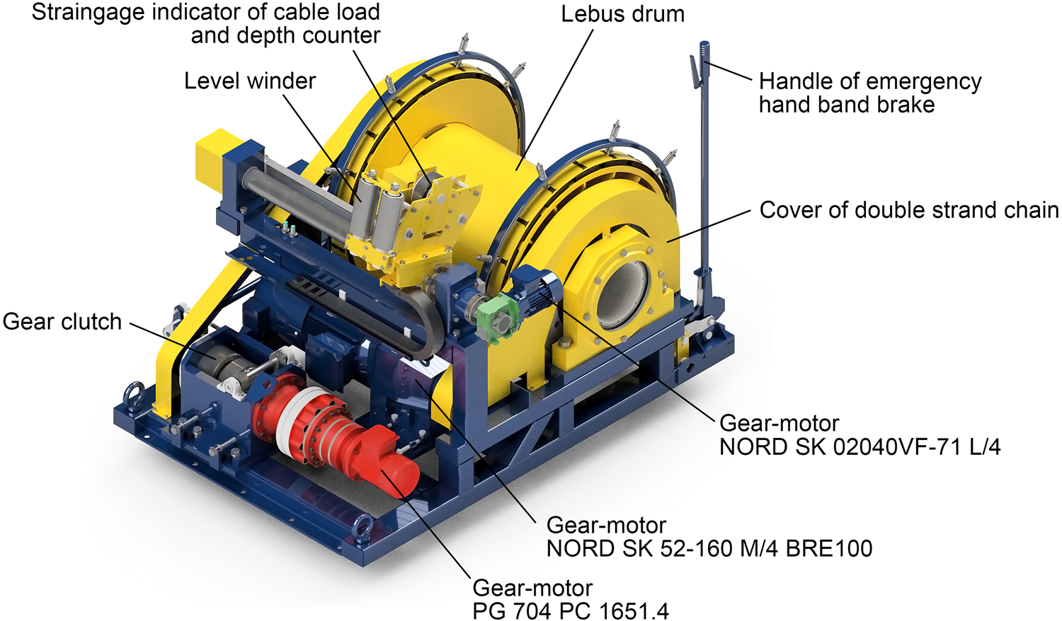
Fig. 4. Structure of the drilling winch.
The Lebus drum capacity is 0.29 m3 which is equipment to 1500 m of a 12.6 mm-diameter cable. The total weight of the winch with the cable is 3214 kg. For transportation by helicopter, the winch can be easily dismounted into two parts of roughly equal weight – the frame with the driving unit and the drum with the cable. The winch has two driving units that operate alternately, depending on the specified mode. During tripping, the winch is geared by an 11 kW electric motor (NORD SK 52-160 M/4 BRE100 FHL TF F, 3 × 380 V, 50 Hz) with braking through a double-strand chain. This system allows a cable winding speed of 0.5 m s−1 with a maximum pull of 20 kN on the mean drum diameter. For drilling and breaking the core, the driving unit is changed with the help of a manually operated gear clutch into a planetary gear (reduction ratio 1651.4:1) with a 0.55 kW PG 704 PC motor. This system allows precise control over the cable winding speed within a range of 1–20 m h−1 and a maximum pull of 40 kN on the mean drum diameter. The winch is equipped with an emergency hand band brake.
To provide a uniform pattern and maintain a fleet angle of ~90° between the spooling cable and drum axis, the winch is equipped with a level winder compatible with the grooving on the drum. The level winder is driven by a separate geared motor (NORD SK 02040VF-71 L/4) at a speed equal to that of the rotational speed of the winch drum with closed-loop motor control. A strain-gage transducer to measure cable load and a depth meter are installed inside the level winder carriage. The drilling winch is bolted to the drilling shelter floor at a distance 2.8 m from the borehole mouth (Fig. 5). To hold the heavy winch, the floor is reinforced by two 200 × 200 mm steel beams.
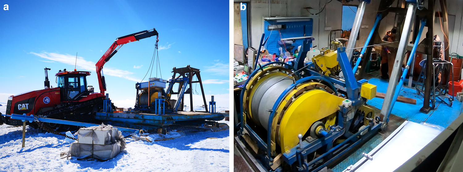
Fig. 5. Drilling winch system: (a) unloading into the movable drilling shelter at Zhongshan Station, Antarctica and (b) view of the drilling winch inside the shelter.
4.2 Armored cable
The armored cable KG (5 × 1.5 + 4 × 0.2)−85 (Fig. 6) consists of five 1.5 mm2 power conductors and four 0.2 mm2 signal conductors. All the conductors are isolated by high-density polyethylene (HDPE) jackets. The larger diameter conductors are used to transmit power to the drill motor and downhole control system. Each of these conductors has a resistance of 13.2 Ω km−1. Meanwhile, the smaller diameter conductors, each of which has a resistance of 89.1 Ω km−1, are used for transmitting analog sensor signals from the pressure chamber of the drill. The overall diameter of the cable is 12.6 mm, the breaking strength of the cable is 85 kN and the cable weight is 0.59 kg m−1.
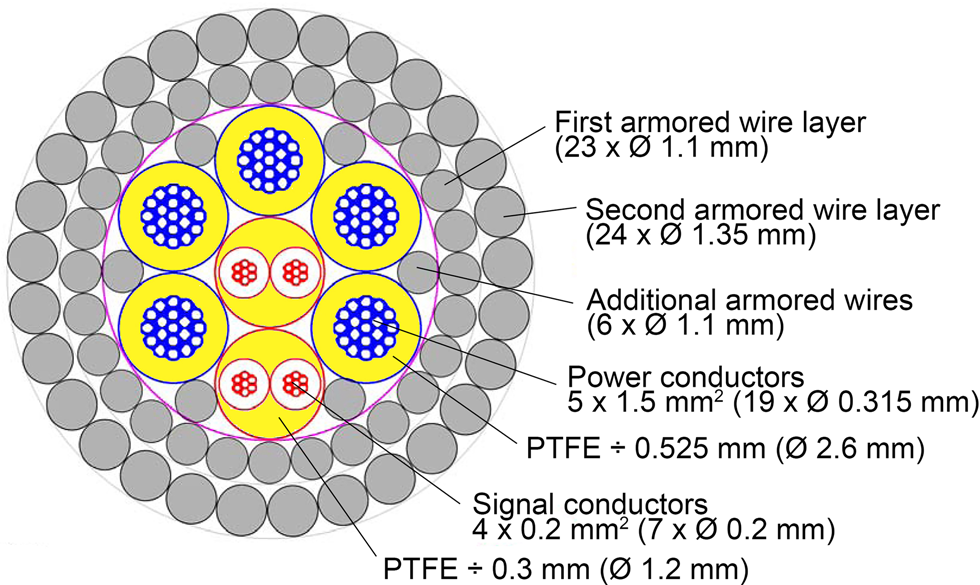
Fig. 6. Structure of the armored cable KG (5 × 1.5 + 4 × 0.2)−85.
The cable, which is suspended from the winch, is guided horizontally to the lower wheel; it then goes upwards to the top wheel and after turning around, connects with the cable termination point of the drill. The angle at which the cable meets the lower wheel is <20°. The winch is operated either by buttons on the control desk or by a remote control with variable speed capacity and frees the operator to walk around and observe the winch and cable in operation.
4.3 Logging winch and cable
The logging winch with its cable is used to suspend logging or other tools during borehole investigation. The design of the logging winch is the same as that of the drilling winch (except for the absence of a driving unit for slow penetration and breaking the core), which makes it possible to use it and its cable as spare parts in the event of failure of the drilling winch and cable. The logging winch is fixed to the floor at the central part of the movable workshop. During logging, opposite doors in the drilling shelter and workshop are opened and the cable suspended from the logging winch is guided from the workshop through the bridge to the dismountable wheel installed near the mouth of the borehole.
5. Pipe handler
The pipe handler is remarkably easy to use for drill servicing at the surface; it significantly saves labor and reduces servicing time and mitigates risk to the staff and ice core in the drilling shelter. The length of the IBED core barrel is 2.4 m and its weight without and with the full core is 36 and 55 kg, respectively. Thus, assembling/disassembling of the core barrel in a vertical position is heavy work and axis misalignment during manual screwing can lead to premature wear in connection threads. The pipe handler, which includes an electromechanically operated clamp and screwing/unscrewing trolley (Fig. 7), is designed to help in holding heavy drill parts during surface servicing.
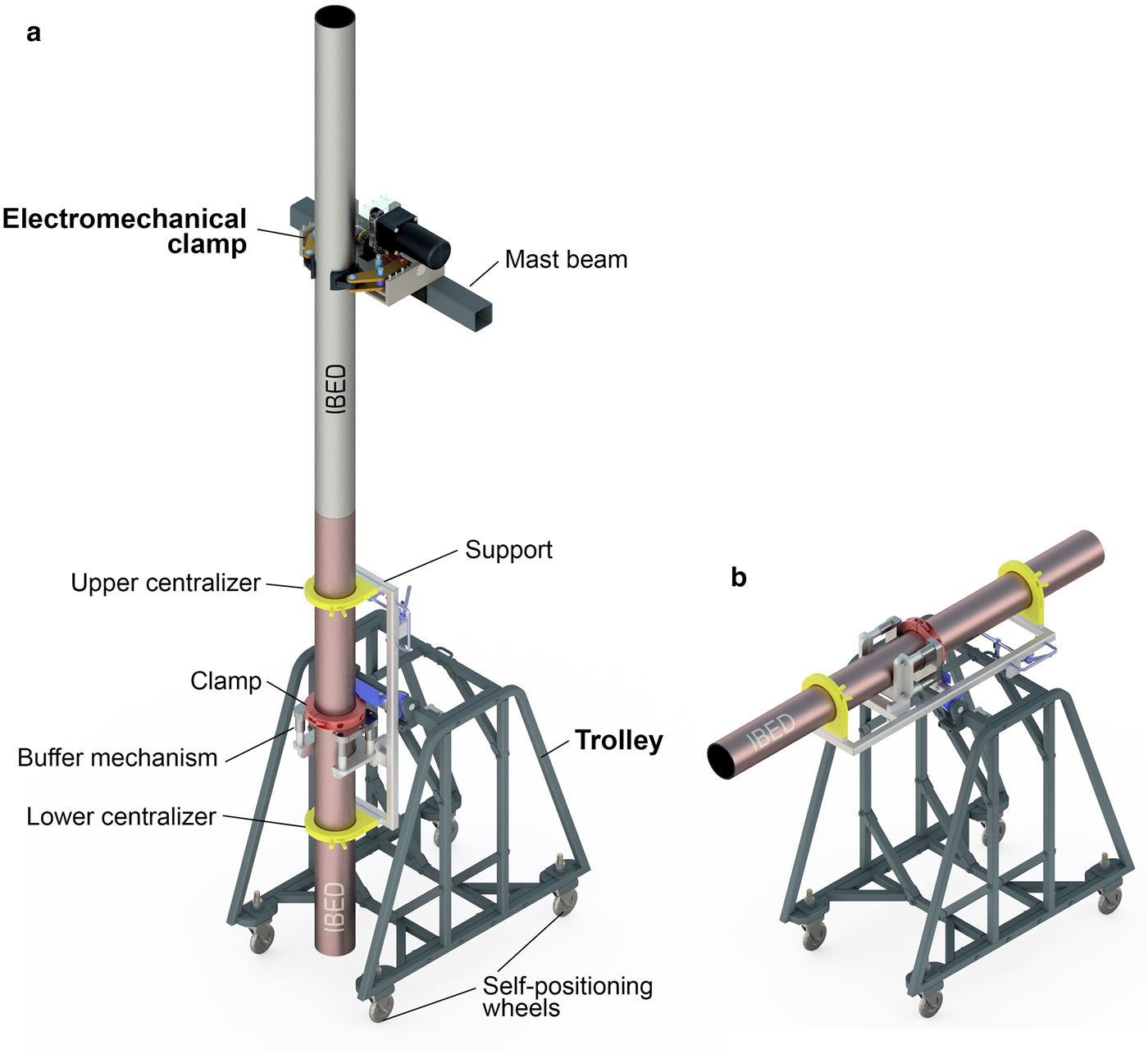
Fig. 7. Pipe handler for (a) screwing/unscrewing pipes and (b) holding pipes in a horizontal position for removing the core from the core barrel.
5.1 Electromechanical clamp
The electromechanical clamp is fixed inside the drilling shelter mast for holding the upper part of the drill when lower pipes are screwed or unscrewed by tunable clamp of the trolley (Talalay and others, Reference Talalay2019b). The clamp is driven by a 200 W, 24 VDC motor (Fig. 8). To clamp the drill, the motor is rotated in the forward direction and torque is transmitted from the motor shaft to the screw stem through the gear reducer. The screw stem has right-hand and left-hand threads on opposite sides. Therefore, when the stem is rotated in the forward direction, the right and left nuts simultaneously move in an outward direction. The nuts push down levers with the help of slips that clamp the drill pipe. To release the drill, the motor rotates in a reverse direction. Three cemented carbide inserts with grooved surfaces are welded to the inner side of each slip to increase friction and clamping torque.
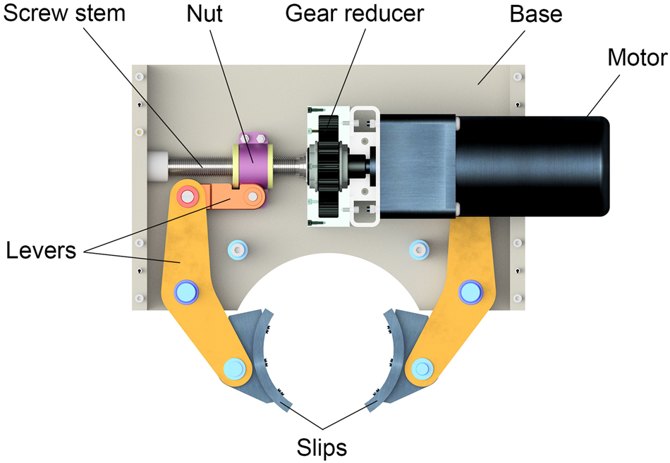
Fig. 8. Structure of the electromechanical clamp.
To ensure that the slips effectively clamp the drill and at the same time cause no deformation in the drill pipe due to excessive clamping force, a control system is designed for the clamp. The clamp is stopped automatically when the DC motor current exceeds the setting limit; clamping torque can be controlled by setting the upper limit of motor current. An electrical schematic diagram of the clamp control system is shown in Figure 9.
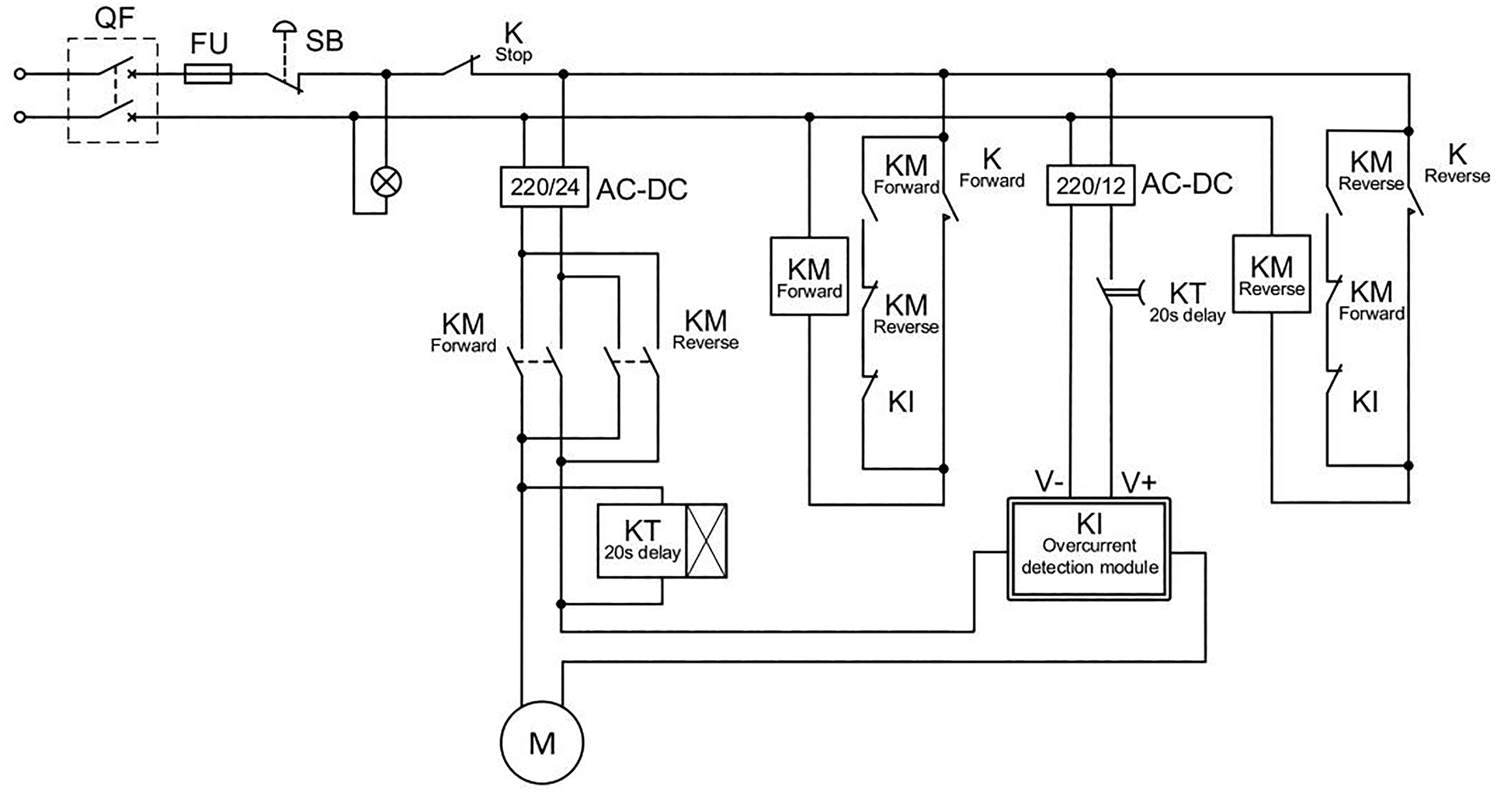
Fig. 9. Electrical schematic diagram of the clamp control system.
To study the relationship between DC motor current, clamping force and clamping torque, proof-of-principle experiments are conducted. These tests also provide a basis for setting a reasonable motor current limit. Experimental results showed that the clamping force increased linearly from 219 to 402 N while the clamping torque increased from 56 to 123 Nm when the current of the driven DC motor increased from 4 to 12 A (Fig. 10). According to the results of joint tests conducted on the electromechanical clamp and screwing/unscrewing trolley, motor current limit should be set at >8 A (clamping torque >86 Nm) during IBED screwing and unscrewing; otherwise, the pipe will slip in the clamp.
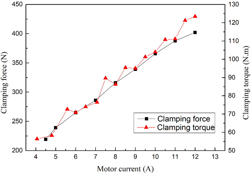
Fig. 10. Clamping force and clamping torque vs DC motor current.
5.2 Screwing/unscrewing trolley
The overall dimensions of the trolley are 1480 × 977 × 600 mm. Four self-positioning wheels are fixed to the bottom of the trolley. A mechanical clamp consisting of two semicircular grippers is used to hold the lower pipe. Four springs are arranged below the clamp, which allow the clamp to move vertically over a certain distance (~50 mm) to compensate for the length of the screw when the pipe is unscrewed. Two centralizers equipped in the upper and lower parts help to keep the drill in a vertical position. The operator turns the clamp by hand with a special key. The trolley support can rotate by 90° together with the core barrel making it possible to turn it from the vertical position to a horizontal position in order to remove the ice core easily (Fig. 11). When the core barrel with the core is disengaged from the drill, the trolley is moved to the ice-core processing table together with the core barrel and ice core.

Fig. 11. Screwing/unscrewing trolley in operation at the Zhongshan Station, Antarctica.
6. ICE-core processing system
Two similar 2.5 m-long and 0.5 m-wide ice-core processing tables were installed in the shelters. The tabletops were made of a 5 cm-thick wooden board. To adjust the height of each table, leveling screws were fixed at the ends of its legs. An aluminum angle bar (2.5 m long) placed on the table is used for taking up the ice core pushed out from the core barrel. After removing the ice core from the core barrel, the operators carry it over to the workshop for simple logging. An electric end saw M1-305, electronic balance QDI-10, a coil with an ice-core plastic bag and a sealing machine are installed on the workshop table. Ice cores are segmented to a length <1 m, weighed, covered with a plastic bag and packed in an insulated foam box after sealing and marking.
7. ICE-chip processing and drilling-fluid recirculation system
This system should be carefully managed because it directly affects the drilling time, environmental issues and cost of the project. It includes (1) an ice-chip vibrator to remove chips from the chip chamber, (2) a centrifuge to separate drilling fluid from chips and (3) a surface drilling-fluid collecting system (Yu and others, Reference Yu2013).
7.1 Ice-chip vibrator
To remove chips, a high-frequency vibrator table driven by two PUTA200/1 motors (200 W, 2940 rpm) was designed (Fig. 12). These motors drive eccentric blocks that produce vibrations with a maximum excitation force of 2.6 kN. Two chip chambers are installed on a platform fixed on a support using springs and secured within a centralizer. A rubber pad is used to reduce vibrations and noise due to collision between steel parts. The removed ice chips fall into a drawer installed below the platform. These chips are then manually packed into cloth bags and placed in a centrifuge for drilling-fluid recovery.

Fig. 12. Ice-chip vibrator: (a) structure and (b) tests in the lab.
To generate the maximum vibration force, the two motors rotate in opposite directions and these vibrations cancel each other in the horizontal direction while a vibration force is superimposed in the vertical direction. A frequency converter is used to control the two vibration motors to ensure synchronized rotation; their rotational speed can be adjusted by adjusting their frequencies when required to obtain different vibration frequencies and forces. Vibrational force can also be optimized by adjusting the mass of the eccentric block.
The IBED uses a bottom circulation system with a downhole pump and chip chamber for filtering the fluid and collecting ice chips. Ice chips are removed from the chip chamber when the drill is lifted to the surface after a coring run. Usually, chips are packed in the chip chamber at a high density of ~350 kg m−3 and their removal presents a complex challenge.
A three-axis acceleration sensor is fixed on the vibrator platform to study the vibration state of the designed system. Experimental results show that vibration acceleration in the vibrator increases with an increase in motor frequency, but vibrations in the X- and Y-directions are much smaller than those in the Z-direction. At an excitation frequency of 40 Hz, vibration acceleration in the Z-direction is 7g while that in X- and Y-directions is <1g (Fig. 13). Thus, the dual-source motor system can automatically reach a state of resonance.
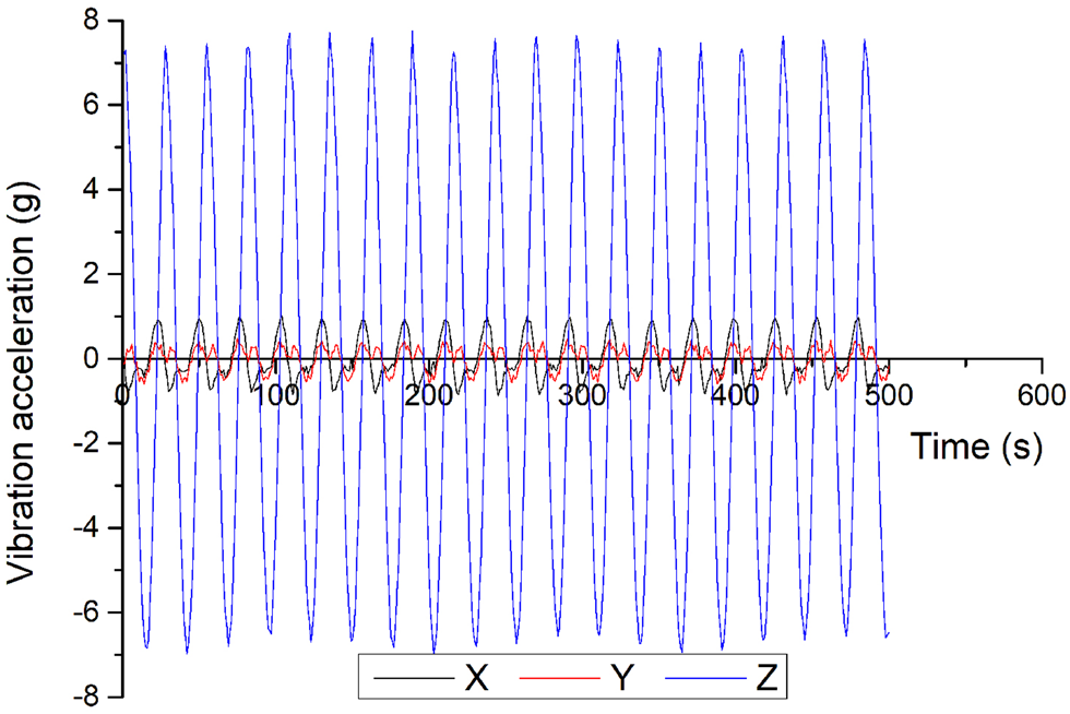
Fig. 13. Changes occurring with time in the vibration acceleration in X-, Y- and Z-directions at a frequency of 40 Hz.
The device was successfully applied in Antarctica in the summer of 2018–2019. According to field tests, under the action of vibration, the chip removal time was ~1 min for a 1.48 m-long ice-chip chamber.
7.2 Centrifuge
Because ice chips contain a large quantity of the drilling fluid, one of the main responsibilities of the recirculation system is to remove as much drilling fluid as possible from the chips. The density of ice chips is similar to that of the drilling fluid and hence conventional drilling fluid cleaning equipment, such as shale shakers or hydrocyclones that are based on gravity clarification, are not suitable for ice drilling. Generally, after removing ice cuttings from the chip chamber, the drilling fluid is separated using hydroextractors, such as centrifuges, and the recovered fluid is recycled back to the borehole.
A tripod SS450-N-type centrifuge is fixed in the drilling shelter beside the vibrator. The overall dimensions of the centrifuge are 980 × 720 × 625 mm and its net weight is 220 kg. The rotating drum of the centrifuge is driven by a belt using a three-phase 380 V, 1.5 kW motor. The maximum weight for drying is 20 kg and drum volume is 17 L. Meanwhile, the maximum rotational speed is set at 1900 rpm. All parts in contact with ice chips are made of SUS304 stainless steel. During centrifugation, the recycled drilling fluid flows directly into the borehole through the hose connected to a guiding tube installed at the borehole head.
7.3 Surface drilling-fluid collecting system
The armored cable carries a large amount of drilling fluid to the surface during tripping operations. A set of surface drilling-fluid collecting devices are designed to recover drilling fluid carried by the cable, including borehole head equipment and collecting trays under the winch and cable. A cable cleaning device with a brush pressed by two nylon plates is placed on the borehole head to remove drilling fluid carried by the winding cable and guide it back into the borehole (Fig. 14). The collecting tray, which has a small slope, is fixed under the winch to collect drilling fluid dropping from the drum cable. The collected fluid flows through a withdrawable drain pan into a bowl-shaped sink around the guiding tube and returns to the borehole through small ports made in the upper part of the guiding tube. Any remaining solids settle at the bottom of the bowl-shaped sink.
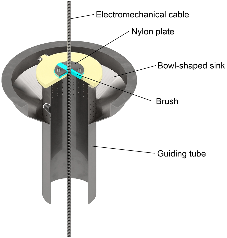
Fig. 14. Arrangement of the borehole head.
8. Maintenance and repair equipment
The maintenance and repair equipment include one workbench in the drilling shelter and two workbenches, a C250 table lathe, a Hangzhou Xihu Z4025 drill press, a BOSH GBG 60-20 grinding machine and other benchwork tools in the workshop.
9. Emergency devices
To remove lost or stuck objects from the borehole, three different fishing drill heads are designed, including a full-diameter magnetic drill head, an annular magnetic drill head and a conical drill head (Talalay and others, Reference Тalalay2015) (Fig. 15). The full-diameter magnet drill head is used to recover lost objects from the top of the core cylinder or from the bottom of the hole in the case of a ‘bottom’ break. The annular magnetic drill head is designed to pick up lost details from the kerf between the wall and core cylinder. The inner and outer diameters of the drill head are similar to those of the cutters in ice drill head. To retrieve broken non-magnetic hardware from the borehole and enable continued coring, the conical drill head is used to cut a recess at the bottom of the hole into which lost details can fall. All the details are later removed by normal coring at this depth. Additionally, the conical drill head can also be used to ream/calibrate borehole diameter if closure occurs. All emergency drill heads have threads similar to those of a normal ice drill head attached to the core barrel.
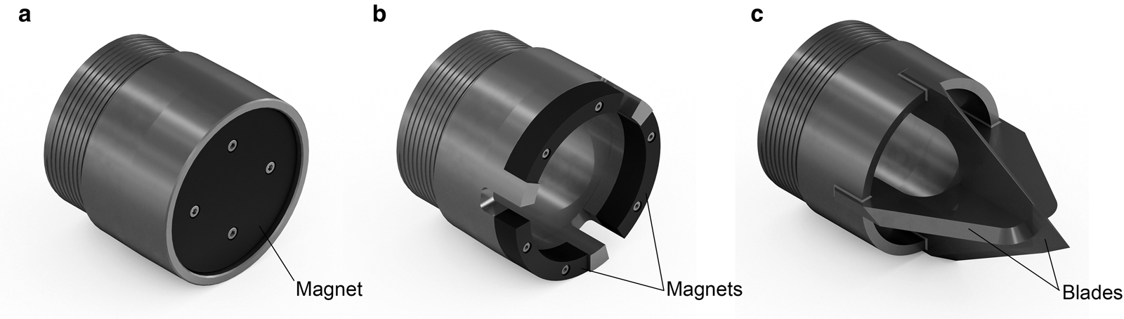
Fig. 15. Fishing tools: (a) full-diameter magnetic drill head, (b) annular magnetic drill head and (c) conical drill head.
Drill sticking is a severe drilling problem that occurs due to borehole closure or accumulation of cuttings. To recover drills stuck in shallow dry holes, a 50 L drum (containing ethylene glycol) and equipped with a 100 m-long hose and hand pump is set up. After heating to ~50°C, the 50% aqueous ethylene glycol solution is delivered through the hose to the accident depth (Talalay and others, Reference Talalay2019a). To recover drills stuck in liquid-filled holes, it is proposed to use a container that can deliver warm deicer directly to the top of the stuck drill.
10. Environmental measures
10.1 Casing
Some of the important parameters in borehole planning include selection of casing, the hole liner used to isolate snow–firn formation, the thickness of which depends on the accumulation rate and temperature conditions at the drilling site. In different regions of inland Antarctica, the depth of firn–ice transition varies from 64 to 115 m (Cuffey and Paterson, Reference Cuffey and Paterson2010). Drilling of uncased holes is technically possible when drilling fluid is transported through a hose lowered into the hole. However, such technology cannot prevent leaks, especially during tripping operations, and in order to reduce drilling-fluid consumption and environmental contamination, the permeable firn zone should preferably be isolated with a casing (Duphil and others, Reference Duphil, Possenti and Piard2014; Talalay, Reference Тalalay2014a).
A HDPE tubing is selected as the casing material. The length and net weight of each casing pipe are 2.5 m and 17.02 kg m−1, respectively, and the inner and outer diameters of the tubing are 204 and 250 mm, respectively. Each individual section of this casing is connected with a threaded pin and the box ends are sealed with a ring gasket and polytetrafluoroethylene tape. The casing may be mounted in 1 d. Pressure testing of the casing connections showed that the suggested sealing method can withstand a pressure of 0.3 MPa (Fig. 16).

Fig. 16. Pressure testing of casing connections.
To seal the casing shoe carefully, a special thermal head is proposed. When casing tubes are run into the hole, electric wires are fixed on their surface with tape. When the shoe of the lower casing tube reaches the bottom of the pre-drilled dry hole, power is supplied to the thermal element and ice begins to melt. The casing is lowered smoothly and heating is stopped when the column is lowered to a depth of 1–2 m into the ice layer. To refreeze water around the shoe and ensure impenetrability of this zone, the casing column is left at rest for some time (<24 h). Once the casing is set down, ice-core drilling continues, beginning from ice inside the casing that can be recovered from the hole. The casing cannot be retrieved.
The thermal casing shoe is made of aluminum and it has inner and outer diameters similar to those of the casing pipe (Fig. 17). A spiral tubular heater arranged in the shell can provide 5.5 kW of heating power. Heating tests proved the high reliability of these heating elements.
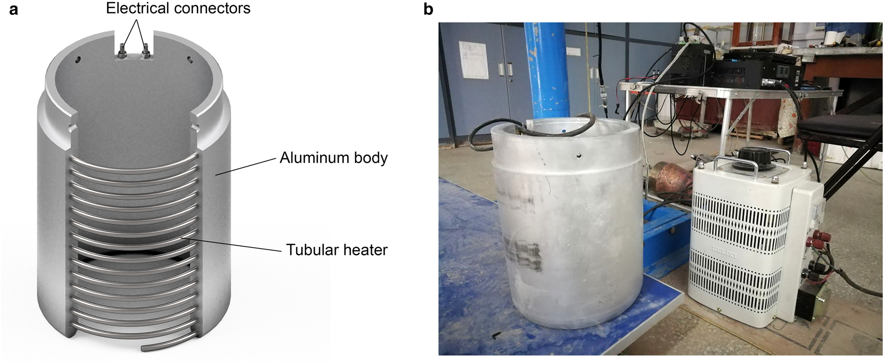
Fig. 17. Thermal casing shoe: (a) structure and (b) heating tests in the lab.
10.2 Bailer
A bailer is designed to recover drilling fluid from the hole at the end of the drilling project. The design of the bailer thread connector is similar to that of the IBED core barrel and hence it can be connected with the upper part of the drill and lowered into the hole using the drilling winch system. Drilling fluid flows inside the bailer through inlet holes at the top of the tube. When the bailer is lifted to the surface, the lower valve is opened to pour out the recovered fluid into the surface container. In total, 32 L of fluid is collected in one bailing run with a 3 m-long bailer. In the field, the collected drilling fluid volume can be increased by extending the bailer to the core barrel and outer barrel of the chip chamber.
11. Conclusions
Most of the auxiliaries described above were tested during the 2018–2019 summer season near Zhongshan Station, East Antarctica while drilling the bedrock to a depth of 198 m. The designed setup has been proven to work well. Purpose-built auxiliaries, such as the pipe handler and chip-chamber vibrator, significantly simplify drill servicing and reduce surface time. However, some improvements are required for precisely controlling the winch speed at low rates, preventing core breakage during handling and processing, and reducing drilling fluid leakage during IBED surface servicing. Because of time constraints in the field, some of the designed auxiliaries (casing, emergency devices and bailer) could not be tested in actual conditions; testing at other sites is planned once full financial and logistical support is obtained.
Acknowledgements
This research was supported by the National Science Foundation of China (project No 41327804) and the Program for Jilin University Science and Technology Innovative Research Team (Project No. 2017TD-24). We thank all teachers, engineers and postgraduate students at the Polar Research Center of Jilin University for their hard work in developing and testing drill auxiliaries and solving various problems. We greatly appreciate fruitful suggestions, useful comments and editing from Scientific Editor K. Slawny (US Ice Drilling Program) and anonymous reviewers.


 Open access