
Abstract
Secondary CLIQ is a quench protection method for protecting high-field accelerator magnets that involves charged capacitors into secondary normal-conducting coils that are magnetically coupled to the superconducting coils. The resulting coupling losses quickly brings the magnet to normal state and safely discharges it.
No direct electrical or thermal link is required between the primary and secondary coils, and robust insulation is placed in between them. The two secondary circuits per magnet are galvanically insulated from the primary circuit, so that the tens to hundreds of CLIQ units needed to protect an accelerator circuit are galvanically insulated from one-another and from the superconducting magnets. The two secondary circuits per magnet each feature a CLIQ unit, and each CLIQ unit discharge is sufficient to bring the magnet to normal state over the entire operational current range. The coil geometry is such that the CLIQ discharge does not raise the voltage over the half-turns of the superconducting coils. After the superconducting coils develop resistance, a significant fraction of the stored magnetic energy is inductively transferred to and dissipated in the secondary coils. The resulting favourable adiabatic hot-spot temperature and voltage-to-ground enables the magnet designer to reduce the copper content of the superconducting coils, and thus lower the overall cost of the magnet.
Secondary CLIQ quench simulations were performed on a hypothetical 14 m variant of the HD2 Nb3Sn dipole with a bore field of 16 T. It is demonstrated that the Secondary CLIQ method protects the magnet over its entire operational current range even in the case where one of the two CLIQ units fails to discharge with an adiabatic hotspot temperature of 248 K and voltage-to-ground of 610 V under nominal protection conditions, and a worst-case adiabatic hot-spot temperature of 263 K and voltage-to-ground of 840 V under fault conditions.
Export citation and abstract BibTeX RIS

Original content from this work may be used under the terms of the Creative Commons Attribution 4.0 license. Any further distribution of this work must maintain attribution to the author(s) and the title of the work, journal citation and DOI.
1. Introduction
This paper presents and discusses a quench protection method for superconducting accelerator magnets, called Secondary CLIQ. This is a novel protection method that seeks to overcome some of the limitations of the typical quench protection methods used for accelerator magnets, which are quench heaters and coupling-loss-induced-quench (CLIQ).
A drawback of the more traditional quench protection method, quench heaters glued to the side of the superconducting coils [1], is firstly that initially only the fraction of the superconducting coils covered by the quench heaters transitions to normal state so that the magnet discharge is comparatively slow. Secondly, quench heaters feature an intrinsic trade-off between effectiveness and electrical integrity: As heat moves from the quench heater through insulation to the superconducting coil, the insulation needs to be as thin as possible to limit the time needed to induce a quench. This is very important for the next generation of accelerator magnets where quench protection imposes design constraints on the magnets [2, 3]. Given that accelerator magnets voltages develop substantial internal voltages immediately after a quench [4, 5] and the quench heater circuits are grounded, having too thin insulation between the heaters and the coils may lead to electrical integrity issues [6], whereas having too thick insulation limits quench heater effectiveness.
The Coupling-loss-Induced-Quench (CLIQ) protection method [7] involves discharging a charged capacitor over sections of the magnet, thus inducing current oscillations and resulting fast changes in the magnetic field. This in turn leads to significant coupling losses inside the superconducting conductors which subsequently transition to normal state. An advantage of this powerful method is that the heating comes from inside the superconducting coil rather than on the edge of it, so the method does not feature the electrical integrity versus effectiveness trade-off as is the case for quench-heaters. CLIQ and quench heaters may be used in complementary fashion, as is done for the HL-LHC inner triplet Nb3Sn quadrupole magnet [8]. CLIQ is also proposed for protecting the 16 T Nb3Sn superconducting dipoles within the FCC-hh accelerator magnet study [9]. A drawback of using CLIQ for protecting an accelerator circuit is that such a circuit typically powers tens to hundreds of magnets, where each magnet would require at least one CLIQ unit. Thus, the circuit comprises tens to hundreds of CLIQ units and the associated current leads and busbars, all connected to a single electrical circuit. This level of circuit complexity raises the likelihood of short-to-ground occurrences.
This manuscript discusses Secondary CLIQ, a protection method for circuits powering accelerator magnets that neither imposes limits on the insulation thickness nor connects the CLIQ units and the superconducting magnets together in a single circuit. Instead, CLIQ units are discharged over secondary normal conducting coils which are inductively coupled but not electrically nor thermally connected to the superconducting magnets. The many CLIQ units and associated equipment (current leads, busbars) needed to protect an accelerator dipole circuit are thus distributed over many galvanically insulated circuits where the occurrence of a short-to-ground in one of the CLIQ circuits does not result in spurious quench detection. Due to innate redundancy and robustness of the Secondary CLIQ method, the circuit can continue to operate without significant intervention.
The secondary coils and CLIQ unit are arranged in a specific manner where the discharge of the CLIQ unit does not result in an increase in the voltage-to-ground in the superconducting magnets. Moreover, after the superconducting coil quenches, a substantial fraction of the stored magnetic energy is inductively transferred and dissipated in the secondary coils, resulting in a substantial lowering of hotspot temperature and voltage-to-ground in the superconducting coils. The secondary coils are subdivided into two circuits per magnet and one CLIQ unit per secondary circuit, where each CLIQ unit discharges sufficient energy to quench the magnet over the entire operational current range. In this manner, Secondary CLIQ enhances fault tolerance by having two redundant and galvanically separated CLIQ units per magnet, where only one of the two CLIQ units is required to function correctly in order to protect the magnet.
The Secondary CLIQ method combines quench protection through inductive coupling (also see [7, 10–13]) and secondary coils for energy absorption ([14–19]) in a novel way, for the purpose of improving quench protection of high-field accelerator magnets, where quench protection considerations (i.e. hot-spot temperature and internal voltages during the discharge) drive the design of the magnet. Preliminary Secondary CLIQ results were previously presented elsewhere [20]. By substantially lowering the hot-spot temperature and voltage-to-ground during a quench, this method aims to be cost-effective by giving the magnet designer the option of lowering the copper content of the superconducting coils, and thus reduce the overall cost.
In this paper, section 2 describes Secondary CLIQ on a conceptual level, discussing robustness, redundancy, and cost-effectiveness. Section 3 discusses Secondary CLIQ simulations that were performed on a previously built and tested experimental Nb3Sn-based dipole magnet called Helmholtz-Dipole 2 (HD2) [21–25], for the purpose of investigating the impact on hot-spot temperature and voltage-to-ground. It is demonstrated through simulation that Secondary CLIQ significantly lowers the hot-spot temperature and peak voltage-to-ground with respect to regular CLIQ, and that the magnet is protected over the entire current range even under fault conditions. Section 4 gives a discussion and conclusions are found in section 5.
2. Concept
2.1. Overall concept
Secondary CLIQ is a quench protection method where capacitors are discharged over secondary normal-conducting coils that are inductively coupled to superconducting coils. Similar to regular CLIQ, this discharge results in rapid magnetic field oscillations over the superconducting conductors, which gives rise to inter-filament and inter-strand coupling losses in these conductors. Consequently, the superconducting coils quickly and efficiently transitions to normal state. As they develop resistance, a significant amount of stored magnetic energy is inductively transferred to the normal-conducting coils and dissipated there [14].
To limit the scope of this manuscript, the Secondary CLIQ concept is presented here specifically for the case of Nb3Sn superconducting block-type coils. In general the concept is more broadly applicable, with the main requirement being that the secondary non-superconducting coils are magnetically coupled to the superconducting coils to induce coupling losses effectively.
Figures 1 through 4 illustrate the proposed layout. The secondary coils, comprising insulated copper windings, are located adjacent to the superconducting coils. The secondary coils are subdivided into forward and rear coils (figure 1), which are connected in series with each-other. One of the poles of the CLIQ unit goes to the electrical mid-point in between the secondary coils and the other goes to the electrically opposite side of the secondary coils (figure 2). This particular configuration gives various benefits:
- When the CLIQ unit is discharged, the forward and rear coils oscillate with opposite polarity (figure 3). The secondary coils thus produce a fast-changing dipole field over the superconducting conductors, but with opposite field orientation in the forward and rear coils. As the net dB/dt over the half-turns of the superconducting coil is zero (in spite of significant local dB/dt), the net induced electric field over each half-turn due to the CLIQ discharge is also zero. This means that the discharge of the CLIQ unit does not raise the voltage-to-ground in the superconducting coil at the moment of capacitor discharge except for minor local variations within the half-turns.
- After the superconducting coil transitions to normal state, a significant fraction of the stored magnetic energy is transferred to the secondary coils [14]. For the HD2 example described in section 3 about 25 % of the stored magnetic energy is dissipated in the secondary coils, which constitute 20 % of the total coil volume. This reduces the voltage-to-ground and hot-spot temperature in the superconducting coils [14], but, due to the anti-symmetric connection of the CLIQ unit to the secondary circuit, does not result in a rise in voltage over the CLIQ unit (figure 3). Even though the secondary coils develop substantial currents after the superconducting coils quench, the current through and voltage over the CLIQ unit never exceeds its initial peak and quickly attenuates after the initial CLIQ discharge.
- During the CLIQ discharge, the net field integral induced by the secondary coils is zero. This means that in the case of a spurious CLIQ triggering, the particle beam passing through the magnet is not pushed out of its trajectory, which may otherwise cause severe damage to the particle accelerator [26].
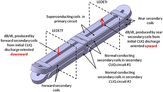
Figure 1. Schematic representation of a superconducting block-coil-design accelerator magnet with inductively coupled normal-conducting secondary coils. The secondary coils are arranged in two circuits (Secondary CLIQ circuits #1 and #2), where each circuit comprises normal-conducting forward and rear secondary copper coils. In the simulations discussed in section 3, the forward and rear sections of the magnet are simulated with the LEDET tool, where LEDETf and LEDETr simulate the forward and rear section of the magnet, respectively.
Download figure:
Standard image High-resolution image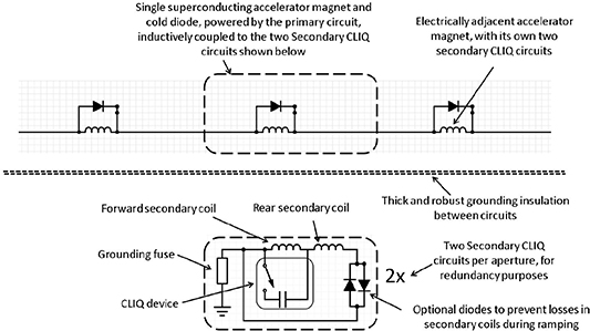
Figure 2. Schematic representation of an accelerator circuit, with hundreds of superconducting magnets in series. Each magnet features two inductively coupled secondary circuits, where each secondary circuit comprises copper coils, a single CLIQ unit, and optional diodes. The optional diodes prevent current transformation from the primary to the secondary coils during regular ramping and during a fast circuit discharge without a magnet quench.
Download figure:
Standard image High-resolution image
Figure 3. Schematic representation of the current flow in each of the the secondary circuits, immediately after the discharge of the CLIQ units (left), and after the magnet transitions to normal state (right)
Download figure:
Standard image High-resolution imageIn addition to subdivision into forward and rear coils, the coils are subdivided into top and bottom coils (figure 4), where the top coils are in Secondary CLIQ circuit #1 and the bottom coils are in Secondary CLIQ circuit #2. Each of the two Secondary CLIQ circuits is connected to a CLIQ unit. The energy stored in the capacitors inside the CLIQ unit is sufficient to bring the magnet to normal state, even when only one of the two CLIQ units is discharging (as demonstrated in section 3). This means that a failure to discharge of one CLIQ unit does not result in an unprotected superconducting magnet. This intrinsic redundancy reduces the required reliability of the triggering system and the CLIQ unit, which would otherwise have to be very close to 100% to provide reliable long-term protection of an accelerator circuit featuring hundreds of accelerator magnets and CLIQ units. Note that CLIQ units are specifically designed with internal redundancies to maximize their fault tolerance. Secondary CLIQ benefits from the fault-tolerance of CLIQ units and in addition requires just one working CLIQ unit out of two to protect the magnet.
Diodes are placed in series with the secondary coils (figure 2), to prevent inductive transformation of current from the primary coils to the secondary coils during magnet ramping and during a fast circuit discharge of a non-quenching magnet [14]. These diodes are optional, given that for a low ramp rate the ramping loss resulting from inductive transformation to the secondary coils may be insignificant.
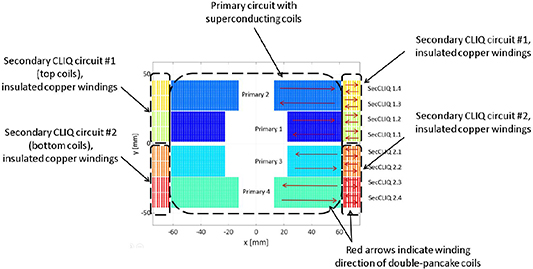
Figure 4. HD2 with primary (superconducting) circuit and two galvanically insulated secondary circuits. Here the red arrows and coil numbers indicate the winding order of the magnet.
Download figure:
Standard image High-resolution image2.2. Robustness
Accelerator circuits are quite sensitive to the occurrence of shorts-to-ground. For example, a previous event where a short-to-ground appeared in the LHC main dipole circuit lead to the spurious quenching of 22 main dipole magnets, as the quench detection circuitry was suddenly exposed to a circuit potential shift of 400 V [27]. A more serious problem is the occurrence of a double short-to-ground, where the discharge of the circuit is uncontrolled with the potential of severe damage to the circuit [28]. Thus, reducing the likelihood of shorts-to-ground is important for guaranteeing the longevity of an accelerator circuit.
Secondary CLIQ resilience to shorts to ground is given by two ingredients. Firstly, given that heat conduction between the primary and secondary coils is not required for quench protection, the insulation thickness may be designed for robustness. For example, in the HD2 example given in section 3, the conductor insulation thickness between the neighbouring copper conductors in the secondary coils is fixed at 500 µm rather than 220 µm for the superconducting conductors and in addition a 1 mm thick layer of insulation is placed between the primary and secondary coils.
Secondly, since Secondary CLIQ does not require a direct electrical connection from the CLIQ unit to the superconducting coil, a hypothetical short-to-ground inside the CLIQ unit does not directly affect the primary circuit, and thus will not lead to spurious quench detection. In principle the Secondary CLIQ circuit with a single short-to-ground will still operate correctly, albeit without a grounding fuse and with a displaced grounding point.
2.3. Redundancy
The protection scheme as presented here considers two CLIQ units per magnet, where each CLIQ unit discharges sufficient energy to efficiently bring the superconducting magnet to normal state over the entire operational current range of the magnet. This means that even when one of the two CLIQ unit fails to trigger, the magnet is still protected. The practical implications of this configuration are discussed extensively in section 3.
To limit the scope of this manuscript, the concept and simulations are applied to a single aperture magnet. In general, the same principle also applies to a double aperture magnet (where the two magnet apertures have a single cold diode in parallel as is the case in the LHC main dipole circuit [29]), with two CLIQ units per aperture and thus four CLIQ units per magnet. Having four CLIQ units per double-aperture magnet further enhances redundancy. The purpose of this paper is to present the concept without considering a variety of magnet configurations. Double-aperture magnets are thus beyond the scope of this paper, but it is nevertheless important to note that applying this method to a double-aperture magnet would further enhance quench protection reliability.
2.4. Cost-effectiveness
The presence of secondary coils significantly reduces the hot-spot temperature and voltage-to-ground in the superconducting coils, in part because a significant fraction of the stored magnetic energy is dissipated in the secondary coils [14].
The price of Nb3Sn magnets is expected to be driven by the price of the conductor [30]. In addition to Nb3Sn, the superconducting conductor comprises a substantial fraction of copper (locally exceeding two-thirds for the FCC-hh baseline designs [9, 31–33]) which undergoes a complex processing route. Unlike the superconducting coil, the secondary coil comprises bulk copper windings, where the associated material costs are orders of magnitudes below that of the superconducting conductor.
It is thus evident that for magnets in which the design is driven by quench protection considerations, i.e. internal voltages and hot-spot temperature during a quench, Secondary CLIQ reduces the need for copper in the superconducting coils, and thus gives the magnet designer the option of lowering the mass and cost of the superconducting coils.
3. Quench simulations on HD2
3.1. Introduction
A series of simulation studies were performed to determine the implications of Secondary CLIQ in terms of hot-spot temperature, peak voltage-to-ground, and redundancy. A 14 m long version of HD2 is taken as reference magnet, for the theoretical case where it is powered at an operating current of 18.6 kA to produce 16 T (figure 5).

Figure 5. Field map op HD2 powered at 18.6 kA. Here the field in the center of the bore is 16 T. Roxie [37] was used both to calculate the magnetic fields over the conductors and the inductive coupling between conductors of the primary and secondary circuits.
Download figure:
Standard image High-resolution imageSimilar studies were previously done on this magnet where a regular CLIQ protection scheme was considered. These studies were done with the simulation code TALES and reference results are available elsewhere [7, 34–36]. The material properties are well-known and the simulations described here use identical parameters as used previously [34, 35], see table 1. The influence of conductor  is also investigated here where
  values of 100 and 300 are considered. The magnetic field map and inductive properties of the HD2 magnet with secondary coils were calculated with Roxie [37] (figure 5).
Table 1. Magnet and conductor parameters.
| Parameter | Value | Parameter | Value |
|---|---|---|---|
Nominal current  [kA] [kA] |
18.6 | Bare cable width [mm] | 22 |
Bore field at  [T] [T] |
16.0 | Bare cable height [mm] | 1.4 |
Peak conductor field at  [T] [T] |
16.9 | Insulation thickness [mm] | 0.11 |
| Operating temperature [K] | 1.9 | Cu:non-Cu ratio | 0.85 |
Differential inductance at  [mH] [mH] |
68 | Filament twist pitch [mm] | 14 |
Stored magnetic energy at  [MJ] [MJ] |
11.8 | Secondary bare cable width [mm] | 10.6 |
| Strands per Rutherford cable | 51 | Secondary bare cable height [mm] | 2.8 |
| Strand diameter [mm] | 0.8 | Secondary insulation thickness [mm] | 0.25 |
The quench simulation model needed to simulate Secondary CLIQ is relatively complex, with multiple galvanically insulated but inductively coupled circuits. The Secondary CLIQ simulation uses a co-simulation [38, 39] of two LEDET [40] models and a PSPICE electrical circuit [41]. The two LEDET models calculate the quench behaviour of the forward and rear part of the magnet simultaneously (See figure 1 'LEDETf' and 'LEDETr'). The inductive coupling between the circuits is internal to the LEDET simulations and a PSPICE network provides the electrical connections inside the various circuits, thus also connecting the forward and rear halves of the magnet together. The resulting voltages-to-ground at all parts of the magnet are calculated with a post-processing step. Both the co-simulation framework [39] and LEDET [40] are part of the STEAM project [38].
To gain confidence that the simulations were configured correctly, multiple cross-checks were done. Firstly, a LEDET standalone simulation of HD2 is cross-checked against the previously executed TALES simulation of the same magnet. Subsequently, a co-simulation comprising two LEDET models and PSPICE is compared to the standalone LEDET model, where the considered PSPICE circuit implements a regular CLIQ configuration (figure 6). These simulation results are discussed in section 3.2.
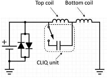
Figure 6. Simulated circuit of HD2 magnet protected with regular CLIQ.
Download figure:
Standard image High-resolution imageSubsequently, Secondary CLIQ simulation results are presented in sections 3.3, 3.4, and 3.5. A comparison of the hot-spot temperature of peak-voltage-to-ground of the regular CLIQ and Secondary CLIQ, including fault condition evaluations, is given in section 3.6.
3.2. Cross-checks with regular CLIQ configuration and comparison between simulation tools
This section discusses comparisons of simulations on the HD2 magnet (figure 5) without secondary coils, powered at 18.6 kA, and protected with a regular CLIQ configuration (figure 7). Previously published TALES simulations [34, 35], standalone LEDET simulations [40], and a co-simulation combining two LEDET models and PSPICE are compared. In the co-simulation model, the secondary coils are present but held at zero current so that they do not affect the discharge of the superconducting coils, and the PSPICE circuit is set up in the regular CLIQ configuration, where the top coils oscillate against the bottom coils during the magnet discharge (figures 6). The CLIQ unit capacitance is 100 mF and the charging voltage is 1000 V.
The three different simulation types give consistent results, where at an operating current of 18.6 kA and a CLIQ discharge delay of 16 mss (accounting for the time required to detect and validate a quench, and subsequently to trigger the CLIQ unit) after the quench onset the resulting adiabatic hot-spot temperature is 349 K and the peak voltage-to-ground is 1610 V. Figure 9 shows the temperature distribution inside the magnet. The consistency between the three different model types (figures 7 and 8) gives confidence that the Secondary CLIQ calculations are not affected by unintentional errors in the modelling implementation.

Figure 7. Cross-checks of simulation models: Here a regular CLIQ discharge over HD2 without secondary coils (where the top and bottom coils oscillate against each other) is calculated. The results of a stand-alone LEDET calculation are calculated with previously performed HD2 TALES calculations [34, 35], and with the more complex simulation featuring a co-simulation of a PSPICE circuit solver and two LEDET quench simulations. The simulation results were found to be consistent in terms of the current discharge (shown here), and voltage discharge (figure 8)
Download figure:
Standard image High-resolution image
Figure 8. Comparison of peak voltage-to-ground in the superconducting magnet, for a regular CLIQ discharge where the top and bottom coils oscillate against each other during the magnet discharge (also see figure 7). As shown in the figure, the voltage-to-ground of the standalone LEDET simulation and the co-simulation featuring the PSPICE simulation tool and two LEDET simulations give consistent results.
Download figure:
Standard image High-resolution image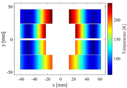
Figure 9. Temperature distribution after discharge, with regular CLIQ configuration at 18.6 kA.
Download figure:
Standard image High-resolution imageAs a side-note, it was previously shown [34, 35] that the manner in which the CLIQ unit is connected to the primary circuit affects the hot-spot temperature and voltage-to-ground, so that optimization beyond the regular CLIQ configuration shown in figure 6 is possible. The most optimal regular CLIQ connection scheme (where different layers inside the top and bottom coils oscillate against each-other) gives a hot-spot temperature of 280 K and a peak voltage-to-ground of 1.2 kV [34, 35].
3.3. Secondary CLIQ with HD2 operating at 18.6 kA without fault conditions
Figure 11 shows the discharge behaviour of the HD2 magnet protected with Secondary CLIQ without fault conditions (figure 10). The CLIQ units are charged at 1200 V, and the capacitance is 100 mF.

Figure 10. Simulated circuits of HD2 magnet protected with Secondary CLIQ, comprising a circuit powering the superconducting HD2 coils and two galvanically insulated Secondary CLIQ circuits.
Download figure:
Standard image High-resolution image
Figure 11. Secondary CLIQ, with nominal quench protection at  = 18.6 kA. After quench detection and validation, both CLIQ units are discharged over the secondary coils. For a RRR of 300 in the superconducting conductor this results in an adiabatic hot-spot temperature of 248 K and a peak voltage-to-ground of 610 V.
Download figure:
Standard image High-resolution imageThe discharge of the CLIQ unit results in current oscillations in the secondary circuits (figure 11) with a peak CLIQ current (equal to the difference in currents between the forward and rear secondary coils) of 7.7 kA. The current in the secondary coils rises to about 25 kA after 0.16 s, at which point the current through the CLIQ units is 0.8 kA. The resulting adiabatic hot-spot temperature and peak voltage-to-ground are 248 K and 610 V. Figure 12 shows the temperature distribution inside the magnet, not including the adiabatic hot-spot zone which reaches a temperature of 248 K. Except for the adiabatic hot-spot zone, the maximum temperature in the primary and secondary coils is 153 K.
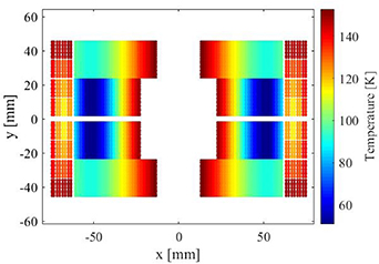
Figure 12. Temperature distribution after discharge, considering a Secondary CLIQ configuration without faults and an operating current of 18.6 kA.
Download figure:
Standard image High-resolution image3.4. Secondary CLIQ with HD2 Operating at 18.6 kA and one CLIQ Unit Failing to Discharge
For an accelerator circuit comprising hundreds of magnets with multiple CLIQ units per magnet, the correct discharging of all CLIQ units with 100 % reliability cannot reasonably be guaranteed. For this reason, it is useful to consider what happens when a CLIQ unit fails to discharge.
Figure 13 shows the result of a simulation where one of the two CLIQ units fails to discharge. As only half the energy is discharged into the magnet, quench protection is now less effective. This results in an elevated hot-spot temperature of 263 K (figure 13) instead of 248 K (figure 11), and an elevated peak voltage-to-ground of 840 V (figure 13) instead of 610 V (figure 11). Figure 14 shows the temperature distribution inside the magnet with a maximum temperature of 162 K, not including the adiabatic hot-spot zone.
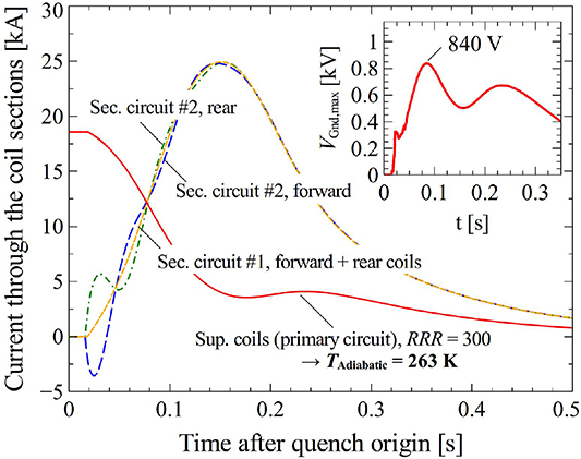
Figure 13. Secondary CLIQ,  = 18.6 kA, where one of the two CLIQ units fails to discharge. For a RRR of 300 in the conductor in the primary circuit, this results in an adiabatic hot-spot temperature of 263 K and a peak voltage-to-ground of 840 V.
Download figure:
Standard image High-resolution image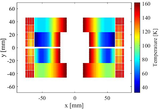
Figure 14. Temperature distribution after discharge, considering a Secondary CLIQ configuration where one of the two CLIQ units fails to trigger. The operating current is 18.6 kA.
Download figure:
Standard image High-resolution imageIn spite of less efficient quench protection, the magnet is still protected when only one of the two CLIQ units discharges. Note that, even when one of the CLIQ units fails to discharge, the associated secondary circuit will still passively absorb stored magnetic energy from the quenching superconducting coils (figure 13).
3.5. Secondary CLIQ with HD2 Operating at 2.0 kA and one CLIQ unit failing to discharge
Figure 15 once again considers the quench behaviour of the magnet where one of the CLIQ units fails to discharge, but now at an operating current of 2 kA. At this low operating current, the current sharing temperature of the superconducting conductor is substantially higher so that more energy is needed to bring the magnet to normal state.
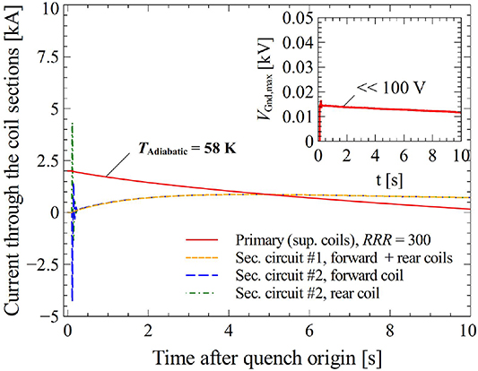
Figure 15. Secondary CLIQ,  = 2.0 kA where one of the two CLIQ units fails to discharge. For a RRR of 300 in the conductor in the primary circuit, this results in an adiabatic hot-spot temperature of 58 K and a peak voltage-to-ground well below 100 V.
Download figure:
Standard image High-resolution imageThe simulation result indicates that even at this low current and with just one of the two CLIQ units discharging, sufficient energy is dissipated into the superconducting magnet to bring it to normal state with a resulting adiabatic hot-spot temperature well below 100 K and a peak voltage-to-ground well below 100 V (figure 15). The peak temperature in the magnet excluding the adiabatic hot-spot zone is 25 K (figure 16).
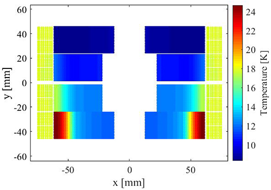
Figure 16. Temperature distribution after discharge, considering a Secondary CLIQ configuration where one of the two CLIQ units fails to trigger. The operating current is 2.0 kA.
Download figure:
Standard image High-resolution imageNote that the peak voltage-to-ground is much lower than the charging voltage of the CLIQ units (1200 V). As explained in section 2, upon discharge of the CLIQ unit, the secondary coils oscillate with opposite polarities, so that the inductive voltage over each half-turn of the superconducting coil is not affected by the CLIQ discharge. In principle the charging voltage of the CLIQ unit may be raised to an arbitrarily large value without raising the voltage-to-ground in the superconducting coil upon discharge, except for a minor local voltage variation along the length of each half-turn. The secondary coil insulation (which is more robust than that of the superconducting coil) does of course have to be robust enough to handle the CLIQ discharge. For the simulations presented here it was found that the peak voltage-to-ground in the secondary coil is equal to the CLIQ charging voltage, and rapidly diminishes after the CLIQ discharge, staying below 200 V after 100 ms.
3.6. Overview of hot-spot temperatures and peak voltages to ground
Tables 2 and 3 give the quench integral QI, adiabatic hot-spot temperature  (See [42] for an explanation of these two terms), and peak voltage-to-ground
  for regular and Secondary CLIQ, where for Secondary CLIQ low current discharges and fault scenarios are considered as well. The RRR of the superconducting conductor is varied between 300 (table 2) and 100 (table 3). The copper in the secondary coils has an conservatively chosen RRR of 100, where a higher RRR was found to moderately raise the effectiveness of the Secondary CLIQ in terms of the hot-spot temperature and peak voltage-to-ground in the superconducting coils. In particular, for a conductor RRR of 300, nominal current and nominal quench protection gives a hotspot temperature of 248 K and a peak voltage-to-ground of 610 V when the RRR of the copper conductor in the secondary coil is 100, and 246 K and 600 V when the RRR of the copper conductor is 300. The presence of magnetic field and higher temperature significantly reduces the difference in resistivity between copper with RRRs of 100 and 300, which explains this modest difference in performance.
Table 2. Resulting hot-spot temperatures and voltages-to-ground for variety of scenarios, where the superconducting conductor RRR is fixed to 300. Here  refers to the operating current of the superconducting magnet, QI refers to the quench integral in the superconducting conductor from the moment of quench origination,
  refers to the adiabatic hot-spot temperature, and
  is the maximum voltage-to-ground found in the superconducting coils.
| Scenario |  [kA] [kA] |
 [MA2s] [MA2s] |
 [K] [K] |
 [V] [V] |
|---|---|---|---|---|
| Regular CLIQ | 18.6 | 34.6 | 349 | 1610 |
| Secondary CLIQ, nominal | 18.6 | 27.9 | 248 | 610 |
| Secondary CLIQ, fault | 18.6 | 28.7 | 263 | 840 |
| Secondary CLIQ, fault | 2.0 | 11.3 | 58 | lt; 100 |
Table 3. Resulting hot-spot temperatures and voltages-to-ground for variety of scenarios, where the superconducting conductor RRR is fixed to 100. Here  refers to the operating current of the superconducting magnet, QI refers to the quench integral in the superconducting conductor from the moment of quench origination,
  refers to the adiabatic hot-spot temperature, and
  is the maximum voltage-to-ground found in the superconducting coils.
| Scenario |  [kA] [kA] |
 [MA2s] [MA2s] |
 [K] [K] |
 [V] [V] |
|---|---|---|---|---|
| Regular CLIQ | 18.6 | 32.5 | 334 | 1420 |
| Secondary CLIQ, nominal | 18.6 | 25.5 | 221 | 553 |
| Secondary CLIQ, fault | 18.6 | 26.3 | 233 | 810 |
| Secondary CLIQ, fault | 2.0 | 7.0 | 40 | lt; 100 |
Figure 17 shows the adiabatic hot-spot temperature and peak voltage-to-ground over a wide current range, considering the most conservative case where only one of the two CLIQ units is discharged and the superconducting conductor RRR is 300. It is shown that the worst-case adiabatic hot-spot temperature and voltage-to-ground of 263 K and 840 V occur at the highest considered current of 18.6 kA. This adiabatic hot-spot temperature and voltage-to-ground under fault conditions compares favorably with the nominal protection provided by the already very efficient regular CLIQ configuration (figures 7, 8, tables 2, 3).

Figure 17. Secondary CLIQ, operating-current-dependent adiabatic hot-spot temperature and peak voltage-to-ground. These results are for the fault scenario where only one of the two CLIQ units discharges. The RRR of the superconducting conductor is 300. Here the symbols are simulation results, and the smooth curves are guides to the eye.
Download figure:
Standard image High-resolution image
4. Discussion
In the Secondary CLIQ configuration presented here the protection redundancy is enhanced by separately discharging CLIQ units into the top and bottom secondary coils. Note however that redundancy may easily be enhanced further by further subdividing the axial coils axially: Instead of having front and rear secondary coils, the secondary coils may be subdivided into four groups of coils axially, with a total of four CLIQ units per magnet. This would further enhance the redundancy and double the deposited power, albeit with extra current leads and with extra cost. The point here is that Secondary CLIQ is flexible, and the level of redundancy may be chosen by the designer.
The analysis presented here does not consider the mechanical stresses that the magnet is exposed to at the moment of capacitor discharge. Such a study goes beyond the scope of the manuscript and would require significant magnet-design and mechanical engineering expertise. Such a future analysis should consider the three-dimensional implications of Secondary CLIQ as well. The secondary coils cover most of superconducting coils so that for the most part inter-filament coupling losses are homogeneously deposited along the length of the superconducting coils. The exceptions are middle and ends of the superconducting magnet which are not covered, which means that normal zone propagates through regular longitudinal quench propagation. This will locally lead to thermal gradients and thus thermal stress. At the same time, as Secondary CLIQ results in more a homogeneous temperature distribution over a larger volume and substantially lower temperatures after a quench (Note the 100 K difference between figures 9 and 12), which means that overall Secondary CLIQ may be mechanically beneficial. Clearly, from a mechanical perspective, a detailed three-dimensional analysis is needed to fully understand the mechanical implications of Secondary CLIQ. It is important to note that the secondary copper coils have superior mechanical properties with respect to the Nb3Sn coils as they comprise dense insulated copper windings. Moreover, these secondary windings may be made from half-hard copper, combining good mechanical and electrical properties [44]. The behaviour of Secondary CLIQ at the moment of CLIQ discharge is expected to be similar to regular CLIQ, and with regular CLIQ no evidence of degradation due to the CLIQ discharge was found in tests on high-field magnets such as MQXF [8] and a double-aperture 11 T short model [43].
As is clear from figure 9, the primary and secondary coils reach a comparable peak temperature after the discharge (not considering the adiabatic hot-spot). This may seem surprising, considering that the superconducting coils first have to develop resistance before energy is inductively transferred to and dissipated in the secondary coils, and the secondary coils thus lag behind the superconducting coils during the discharge (figure 7). However, whereas the Cu:non-Cu ratio in the superconducting coils is 0.85 and voids in the cable are filled with epoxy, the secondary coils comprise only insulated copper. In normal state, the resistivity of the secondary coils is thus significantly lower than that of the superconducting conductor for a given temperature and magnetic field. The current and power distribution between the primary and secondary coils is amongst other factors determined by resistance ratio of the two circuits, where a lower circuit resistance results in more current and dissipation in that circuit. The secondary coils thus catch up in temperature to the superconducting coils. With nominal protection at nominal current in HD2 (figure 11), the secondary coils dissipate 25 % of the total stored magnetic energy in spite of just comprising 20 % of the coil volume. For quench protection purposes, the total effective coil volume is thus increased, but importantly this is done without increasing the distance from the superconducting conductors to the bore, and thus the efficiency by which they contribute to the bore magnetic field.
In general, the lower the copper fraction of the superconducting conductor, the more energy is inductively transferred to the secondary coils during the discharge, and thus the more efficient Secondary CLIQ becomes.
It would seem that Secondary CLIQ adds to the complexity of superconducting coils by introducing extra coils. Nevertheless, the benefit provided in terms of hot-spot temperature and voltage-to-ground reduces the constraints of the superconducting coils themselves. For example, introducing Secondary CLIQ to FCC-type block-type coils may obviate the need for grading (see for example [46]) inside the superconducting coil. Given that graded superconducting coils come with constraints that are not present for the secondary coils described here (for example, all superconducting coils have to produce a magnetic field with a very high field quality and joints are needed between the graded sections), replacing a graded with an ungraded coil design in combination with Secondary CLIQ may reduce the overall complexity of the design.
5. Conclusions
This paper discusses a novel quench protection method called "Secondary CLIQ". This method involves discharging capacitors into secondary normal-conducting coils resulting in significant coupling losses in the superconducting coils, a rapid transition to normal state, and a favourable worst-case hot-spot temperature and voltage-to-ground.
A specific secondary coil geometry is chosen where a CLIQ discharge does not raise the voltage-to-ground in the superconducting coils at the moment of discharge, and a significant fraction of the stored energy of the superconducting coils is inductively transferred to and dissipated in the secondary coils during the magnet discharge. No direct electrical or thermal connection is needed between the secondary coils and the superconducting coils, so that robust insulation may be introduced between them. The secondary coils are subdivided into two galvanically insulated circuits where a CLIQ unit discharge in one of the two secondary circuits is sufficient to bring the superconducting magnet to normal state over the entire operational current range. These features contribute to robust and fault-tolerant quench protection.
As the Secondary CLIQ method gives favorable hot-spot temperatures and internal voltages inside the superconducting magnet, the amount of copper in the superconducting coil may be reduced, thus giving the magnet designer the option to lower the copper content in the superconducting coils and lower the overall cost of the magnet.
A series of Secondary CLIQ simulations were done on HD2, where the impact of operating current, the occurrence of CLIQ unit triggering faults, and the superconducting conductor RRR on the hot-spot temperature and peak-voltage-to-ground were evaluated. It is demonstrated that under nominal protection conditions the resulting hot-spot temperature is 248 K and voltage-to-ground is 610 V. Under fault conditions where one of the two CLIQ units fails to discharge, the Secondary CLIQ method gives worst-case hot-spot temperatures of 263 K and a voltage-to-ground of 840 V over the entire current range.
The simulation results illustrate that the Secondary CLIQ quench protection method is an interesting and promising option to consider for protecting high-field accelerator magnets, which merits experimental investigation.
Acknowledgments
The authors would like to thank Tiina Salmi, who contributed to the original studies on secondary coils. The HD2 magnetic model used as input for the LEDET simulations was created by GianLuca Sabbi and retrieved from the CERN TE-MSC Roxie repository. The simulations presented here build on previous TALES simulation work by Jonas Blomberg Ghini. This paper benefitted from feedback and comments from various people, including Arjan Verweij, Gijs de Rijk, Susana Izquierdo Bermudez, Clement Lorin, Douglas Martins Araujo, as well as the reviewers. The authors would like to thank the various contributors.