

Abstract
ZrO2 ceramic has a wide range of applications, such as in the thermal barrier coating (TBC) of turbine blades, micro actuators, and gas sensors. However, this material is challenging to machine due to its high hardness and brittleness. Although spark assisted chemical engraving (SACE) can be used to machine ZrO2 ceramics, the traditional SACE models for glass are difficult to apply to ZrO2 ceramics since the melting point of ZrO2 is much higher than that of glass. A theoretical basis for applying the SACE process to ZrO2 ceramics is still lacking, which makes applying the SACE process to machine micro cavities with high surface quality in ZrO2 ceramics very challenging. This paper proposes an energy action model based on the processing voltage, pulse width and machining gap by analyzing the energy transfer process of SACE. The energy model expresses difference in the spark energy between physical removal and chemical removal. Through machining experiments, the contact effect of the SACE process on ZrO2 ceramics was found, and the reasons why the SACE process is sensitive to the machining gap were clarified. Furthermore, physical and chemical removal process models with or without the discharge constraint onto the end of the tool electrode were established. Using the above theoretical models, a circular ring microcavity without micro cracks on the surface was achieved in a ZrO2 ceramic workpiece by using the SACE process with the regulating energy effect trending to the chemical removal. Additionally, considering the contact effect and the process models applied in the SACE scanning process of ZrO2 ceramics, a tool electrode with a spring structure was employed to solve the bending problem of the micro tool electrode. As a result, a square micro-cavity with high surface quality was machined successfully.
Export citation and abstract BibTeX RIS
1. Introduction
ZrO2 ceramic is a kind of advanced functional material with a high melting point, a low thermal expansion coefficient, high mechanical strength, and biocompatibility. It has a wide range of applications in the fields of aerospace, biomedicine, and electronic communication [1], such as ceramic dentures, the thermal barrier coating (TBC) of turbine blades, micro actuators, and gas sensors [2]. In particular, TBC using yttria-stabilized zirconia (YSZ) ceramics can protect the turbine blades and thus allow them to operate at higher temperatures in aero-engines [3, 4].
However, it is difficult to achieve the efficient and damage-free machining of ZrO2 ceramics due to their material properties of high hardness, brittleness, and non-conductivity. For the machining of ZrO2 TBC, ultrasonic machining is employed to penetrate the ceramic coating [5], however this method is inefficient and is prone to causing damage in the form of microcracks on the machined surfaces. Conventional laser machining also causes microcracks on the material surfaces of ZrO2 ceramics due to the effect of heating [6, 7]. Although femtosecond laser machining can achieve the damage-free processing of ZrO2 TBC by constraining the single pulse energy [8], it is inefficient and costly. Therefore, there is an urgent need for the efficient, low-cost, and damage-free processing of ZrO2 ceramics.
As a low-cost nontraditional process, spark assisted chemical engraving (SACE) can be used to machine non-conductive hard and brittle materials through the combination of physical and chemical effects. The basic principle of SACE is described as follows. A tool electrode and an auxiliary electrode are usually immersed in an alkaline electrolyte. A gas film is formed on the surface of the tool electrode from the action of the electrolytic bubble. The gas film plays a role as the dielectric medium for the electric discharges between the electrolyte solution and the tool electrode. Under the action of high temperature and high pressure generated by the discharging sparks, the physical and chemical removal of workpiece materials occurs [9]. A 2018 study proved that, in the application of the SACE process to ZrO2 ceramics, the material removal mechanism involves as the combination of physical removal and chemical etching, and obtained the quantitative ratio of physical and chemical removal by the analysis of processed products [10]. The chemical etching process can help to achieve high surface quality without the damage of microcracks.
However, the SACE process with high surface quality has not yet been realized in ZrO2 ceramics up to now. This challenging goal requires a clear understanding of the material removal process of SACE. The published literature reveal that the material removal process during SACE has not been well understood yet [11–16]. Currently, the melting and etching, which occurs when the machining temperature is higher than the melting temperature of glasses, is considered as the material removal mechanism of glasses in SACE [16, 17]. Jalali et al (2009) quantitatively characterized the mechanism of thermal heating and chemical etching during SACE by estimating the machining temperature to be around 600 °C [15]. Ziki et al (2012) calculated the machining temperature to be about 500 °C by measuring the thermal elongation of a tool electrode during SACE [18]. A machining temperature of 500 ∼ 600 °C can melt glasses, however it cannot melt ZrO2 ceramics with the melting point of 2700 °C. This indicates that the material removal mechanism of ZrO2 ceramics in SACE is different from that of glasses. Additionally, high temperature is a necessary condition for the chemical reaction between ZrO2 and NaOH electrolyte. Qiu et al showed that ZrO2 is insoluble in NaOH electrolyte at room temperature, and even at 300 °C its solubility is still very small (1–10)•10−8 mol L−1 (Based on a 1000-hour experiment) [19]. Wilke et al (2012) showed that high-temperature and high-pressure conditions greatly increased the solubility of ZrO2 in NaOH solution; for example, at 300 °C and 60 MPa, the solubility was 32 ppm, while at 600 °C and 930 MPa, the solubility reached 390 ppm [20]. He et al (2018) showed that under the action of high-temperature and high-pressure from sparks in SACE, NaOH electrolyte and ZrO2 underwent a stronger chemical reaction [10]. However, the theoretical basis for the SACE processing of ZrO2 ceramics is still lacking. In the SACE process, the machining gap between the tool electrode and the workpiece surface has an important influence on the processing effect, however the mechanism behind this influence is still unclear. Currently, gravity feeding with zero machining gap [21–24] is the most common feed strategy, though it tends to cause tool electrode bending. It is necessary to reveal the influence mechanism of the machining gap on the SACE process.
For the purpose of studying the effect of spark energy and machining gap on the SACE process, the process of spark energy transferal and its physical and chemical removal effects were first analyzed. A model of spark energy based on the processing voltage, pulse width, and machining gap was proposed. The physical and chemical removal processes of ZrO2 ceramic under different spark energies and machining gaps were experimentally studied to verify the energy model. Thus, it was obtained that a chemical removal leading optimization process for machining typical microcavities with high surface quality in ZrO2 ceramics. Furthermore, to avoiding the bending of the tool electrode in the 3D-scanning SACE process, a tool electrode with a spring structure was fabricated and employed to improve the machining process of ZrO2 ceramics.
2. Analysis of spark energy effect on physical and chemical removal in SACE process
2.1. Analysis of SACE process considering spark discharging conditions
SACE achieves the removal of workpiece material by the physical and chemical process under the action of spark discharges. The discharging process is shown in figure 1. A tool electrode, a gas film, and an electrolyte film are the necessary components for generating spark discharges. Under the action of a processing voltage, the surfaces of the tool electrode and the auxiliary electrode undergo electrolysis to generate bubbles. As the bubbles are continuously generated and merged (figure 1(a)), a gas film is formed on the surface of the tool electrode, which separates the tool electrode from the electrolyte. Then, the negative charges move toward the surface of the tool electrode, and positive charges move toward the surface of the electrolyte film (figure 1(b)). When the charged voltage reaches a certain value, spark discharges occur, thus creating a high temperature and high pressure environment within the electrolyte (figure 1(c)). In the SACE process, the spark energy determines the high temperature and high pressure of the active region, which has an important influence on the processing effect. Additionally, in order to ensure that the high temperature and high pressure can act on the workpiece surface to achieve material removal, the workpiece must be enough close to the discharging position to reduce the loss of spark energy in the electrolyte. Thus, the transfer process of the spark energy was studied in terms of its effects on physical and chemical removal in the SACE process.

Figure 1. Discharge process in SACE (HTHP: high temperature and high pressure).
Download figure:
Standard image High-resolution image2.2. Modeling of spark energy for a chemical removal dominated process
The high temperature and the high pressure from spark discharges on the workpiece surface lead to the physical and chemical removal of the ZrO2 material [10]. The spark energy transferal process is shown in figure 2. A spark with an initial energy Qinit passes through the gas film and the electrolyte film before it acts on the workpiece surface. The extremely high temperature of the spark heats and vaporizes part of the electrolyte as the loss of some energy Qloss, which is positively correlated with the thickness h of the electrolyte film. The thickness h and the initial energy Qinit determine the spark energy Q that ultimately acts on the workpiece surface. This energy Q directly affects the effect of the physical and chemical removal of the workpiece material. Besides, considering that the spark also loses some energy in the form of light, radiation, etc, the energy Q can be expressed as:


Figure 2. Transfer and distribution process of spark energy.
Download figure:
Standard image High-resolution imagewhere Q is the spark energy that ultimately acts on the workpiece surface, Qinit is the initial spark initial energy, Qloss(h) is the loss energy when the spark passes through the electrolyte, and  is the loss energy from other forms.
In SACE, the electrical power of sparks can be derived from the voltage and current as follows:
where Qinit is the initial spark energy, tspark is the duration of a single spark, I(t) is the discharge current, and U(t) is the discharge voltage. Obviously, the spark duration tspark is an important factor affecting the initial spark energy Qinit. The value of tspark is affected by the deionization of the discharging channel. If the discharging channel could have sufficient time to deionize (tpulse-off≥ tdeionization), a continuous discharge could not occur, in which the pulse interval tpulse-off represents the shortest interval between adjacent discharges, and tdeionization is the minimum time of the deionization. If the discharging channel could not have sufficient time to deionize (tpulse-off < tdeionization), a continuous discharge even into an arc discharge with high brightness might occur, resulting in an increase of the spark duration tspark which could generate excessive heat to damage the workpiece surface. Therefore, to avoid the occurrence of continuous discharge, it is necessary to constrain the spark energy to ensure that tpulse-off≥ tdeionization.
The spark energy Q is positively correlated with the local temperature Tzone of the workpiece surface caused by a spark. According to equations (1) and (2), the relationship between Tzone and the processing parameters can be obtained as:
where dgap is the machining gap between the tool electrode and the workpiece surface, hgas film is the gas film thickness, and dgap—hgas film is equal to the thickness h of the electrolyte film. Tzone is the local temperature of the workpiece surface caused by a spark. tspark is the spark duration affected by tdeionization and tpulse-off. Equation (3) shows that Tzone can be adjusted by changing the processing voltage, pulse interval, and machining gap. If Tzone could not satisfy the condition of high temperature, workpiece material removal would not occur in the SACE process. This means that there is a critical temperature Tc of the material removal. In this study, the critical temperature of chemical removal is expressed by Tccr, and the corresponding critical spark energy is expressed by Qccr. Similarly, the critical temperature of physical removal is expressed by Tcpr, and the corresponding critical spark energy is expressed by Qcpr.
The key solution of damage-free process is to achieve the energy leading to the dominantly chemical removal on machined surfaces by adjusting the processing parameters. Physical removal can occur only if Q> Qcpr. Chemical removal can occur only if Q> Qccr. If Qcpr> Qccr and Qcpr> Q > Qccr can be realized by adjusting Qloss(h) to control Q according to equation (1), the damage-free process can be realized due to the lack of physical removal. For determining the feasibility of chemical removal dominated damage-free process, it is necessary to compare Qcpr and Qccr experimentally.
3. Basic experiments of spark energy effect
According to equation (3), the spark energy Q acting on the workpiece can be adjusted by changing the processing parameters and the machining gap dgap. In order to investigate the effects of different spark energies on physical and chemical removal, basic experiments with different initial machining gaps and processing voltages were performed on a dense ZrO2 ceramic produced by sintering.
3.1. Experimental systems
Figure 3 shows the experimental system consisting of a tool electrode, an auxiliary electrode, a ZrO2 workpiece, a liquidometer, a force sensor, a tilt table, a Z-axis spindle, an XY-axis worktable, and a CNC system. The auxiliary electrode uses a graphite block with dimensions of 40 × 40 × 5 mm to increase resistance to electrolytic corrosion. The liquidometer was used to read the level of the electrolyte with a resolution of 0.1 mm. The force sensor was used to measure the force on the workpiece surface with a resolution of 0.5 g. The tilt table was used to adjust the workpiece tilt for leveling the workpiece surface. The positioning accuracy of the XY-axis and the Z-axis was ±1 μm and ±0.5 μm respectively. The experimental parameters are shown in table 1. Before the experiments, the following preparatory steps were performed [25]: the surface of the ZrO2 workpiece was leveled, the end of the tool electrode was flattened, the immersion depth of the tool electrode was adjusted, and the initial machining gap was set.
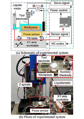
Figure 3. Schematic and photo of experimental system. (a) Schematic of experimental system. (b) Photo of experimental system.
Download figure:
Standard image High-resolution imageTable 1. Experimental parameters.
| Parameter | Initial value |
|---|---|
| Diameter of tool electrode (mm) | Φ0.5 |
| Material of tool electrode | Copper |
| Material of workpiece | ZrO2 ceramic |
| Pulse duration (μs) | 3.2 |
| Pulse interval (μs) | 4.8 |
Output voltage ( ) ) |
90–150 |
| Immersion depth (mm) | 2 |
| Electrolyte concentration (wt%) | 5 |
| Electrolyte type | NaOH solution |
3.2. Experiments of spark energy effect under a given machining gap
Under the conditions given in table 1 with a processing time of 30 s, experiments were performed by using different initial machining gaps and processing voltages. Figure 4 shows the experimental results observed with an optical microscope. As shown in the figure, for a machining gap of ≤15 μm and a voltage of 150 V, the machined surface showed obvious signs of thermal spalling, indicating the dominance of physical removal over chemical removal. Meanwhile, for a gap of ≥20 μm regardless of the voltage of 120 V or 150 V, the machined surface was smooth and shallow, indicating only chemical removal without physical removal, namely Qcpr> Q> Qccr. For a voltage of 120 V and a gap of ≤15 μm, the workpiece surface showed the combined effect of physical and chemical removal. For a voltage of 120 V and a gap of ≥20 μm, there were no obvious machining marks. For the first result of 150 V, a large number of microcracks are visible, indicating that serious surface damage was caused by the larger spark energy, although the material removal rate was higher.

Figure 4. Processing effects at different processing voltages and initial machining gaps.
Download figure:
Standard image High-resolution imageAs shown in figure 4, when the initial machining gap was increased from 15 μm to 20 μm under a voltage of 120 V, the processing effects changed abruptly. Furthermore, the experiments were performed using initial machining gaps of 16 μm, 17 μm, 18 μm, 19 μm, 20 μm, 21 μm, and 22 μm, respectively. As shown in figure 5, the abrupt change occurred at a machining gap of 20 μm. As we know, a tool electrode thermally expands due to spark discharges in the SACE process [18]. In the experiment with an initial machining gap of 20 μm, the force sensor showed that the tool electrode after thermal expansion was in contact with the workpiece surface, resulting in the obvious material removal. However, for an initial machining gap of 21 μm, when the tool electrode after thermal expansion was not in contact with the workpiece surface, the removed amount of workpiece material was extremely small. Even if the initial spark energy was increased or the processing time was extended to dozens of minutes, obvious material removal did not occur due to the fact that the tool electrode was not in contact with the workpiece surface during the SACE process. In this paper, this phenomenon is named the 'contact effect'. The contact effect can explain the SACE sensitivity to the initial machining gap. This indicates that a necessary condition for the effective removal of ZrO2 ceramic material during the SACE process is to ensure direct contact between the tool electrode and the workpiece.
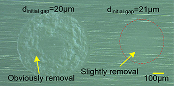
Figure 5. Contact effect of SACE on ZrO2 ceramics.
Download figure:
Standard image High-resolution image3.3. Analysis of spark energy model under contact effect
To achieve a damage-free process by inducting the dominantly chemical removal, the spark energy Q acting on the workpiece surface needs to satisfy Qcpr> Q> Qccr. In this study, this was achieved by adjusting the electric parameters, the electrolyte thickness, and the initial machining gap. For the damage-free process under the contact effect, the processing voltage was adjusted so as to change of the value of Q to investigate the effect on the material removal.
Figure 6 shows the experimental results obtained by white light interferometer (WLI) and scanning electron microscope (SEM). At the processing voltage of 150 V, the material removal starts from the edge of the tool electrode end, and then gradually extends inward until the workpiece material under the tool electrode is removed completely. The processed surface from the dominantly physical removal is very rough as the energy Q is greater than the critical energy Qcpr of physical removal. At a processing voltage of 90 V, the initial pattern of material removal is similar to that at 150 V since the dominantly physical removal due to the very narrow machining gap making Q> Qcpr. With increasing processing time, the processed surface becomes increasingly smooth and fine, indicating the effect of chemical removal. In this case, the damage-free process was realized by achieving Qcpr> Q> Qccr, that is, dominantly chemical removal. In fact, in the case the discharge constraint effect appeared in the SACE process due to the small spark energy at a voltage of 90 V [23]. The discharge constraint causes the discharge area to be concentrated at the edge of the tool electrode end, leading to the unremoved areas in the center of the end face of the tool electrode. Obviously, the discharge constraint has an important influence on the energy distribution and processing results.
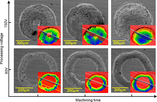
Figure 6. Gradual change process of material removal under contact effect.
Download figure:
Standard image High-resolution imageTo explain the experimental results shown in figure 6, models of the SACE process under the contact effect were established for ZrO2 ceramics. Figures 7 and 8 show the process models without the discharge constraint (for example, 150 V in figure 6) and with the discharge constraint (for example, 90 V in figure 6), respectively.
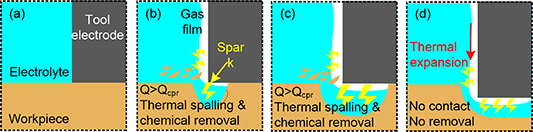
Figure 7. SACE material removal process on ZrO2 ceramics without discharge constraint.
Download figure:
Standard image High-resolution image
Figure 8. SACE material removal process on ZrO2 ceramics with discharge constraint.
Download figure:
Standard image High-resolution imageAs shown in figure 7, when the spark energy is too large to constrain the discharges onto the edge of tool electrode end, the discharges occur across the whole of the surface of the tool electrode including the end and its side wall under the electrolyte. In the initial SACE process under the condition of tight direct contact, there is no electrolyte between the end face of the tool electrode and the surface of the workpiece, as a result of no discharges under the end face (figure 7(a)). When discharges occur at the boundary of the tool electrode end, the electrolyte film h passed by the sparks is very thin, which means that the energy Q can be sufficiently large to satisfy Q > Qcpr due to a low energy loss Qloss(h). The dominantly physical removal mainly occurs in the form of thermal spalling, resulting in terrible surface quality (figure 7(b)). With the increase of the amount of removed workpiece material, the electrolyte flows into the gap to cause discharges to occur at the gap. In this way, the workpiece material below the tool electrode end can be continuously removed (figure 7(c)). When the workpiece material in contact with the tool electrode is completely removed, the material removal process is stopped regardless of the physical or chemical removal since the contact effect cannot occur (figure 7(d)). Therefore, if the discharge energy is large to Q > Qcpr as no discharge constraint, it usually results in a poor surface quality such as the processing results at a voltage of 150 V shown in figure 6.
As shown in figure 8, when the spark energy is small enough to bring the discharge constraint, the discharges are mainly concentrated at the edge of the tool electrode end. In the initial stage of the SACE process, the energy Q can still be large enough to satisfy Q > Qcpr due to a low energy loss Qloss(h) resulting from the very thin electrolyte film h passed by the sparks (figure 8(a)). In this case, similar to the process shown in figure 7(b), the material removal is achieved by the combination of thermal spalling and chemical removal (figure 8(b)), however the proportion of physical removal under the lower energy condition is relatively smaller than that in figure 7(b). The material removal causes the electrolyte film thickness h and the loss energy Qloss(h) to increase simultaneously, meaning that the energy Q is decreased, thus reducing the physical removal effect. Until the energy Q decreases so as to satisfy Qcpr > Q > Qccr, although the thermal spalling is stopped, the chemical removal continues to occur, thus improving the surface quality (figure 8(c)). As the material continues to be removed, the thickness of the electrolyte film continues to increase, thus decreasing the energy Q. Until Q < Qccr, the chemical removal is also stopped and the workpiece material is no longer removed (figure 8(d)). The effect of the discharge constraint can improve the surface quality, however leads some unremoved material under the end face of the tool electrode.
Therefore, in order to realize high surface quality when using SACE process on ZrO2 ceramics, it is necessary to achieve the discharge constraint by adjusting the processing parameters. According to equation (3), the spark energy Q can be adjusted by changing the pulse interval and processing voltage. In this research, the discharge constraint can be realized under the conditions of a processing voltage of 90 V, a pulse duration of 3.2 μs, and a pulse interval of 6.4 μs. It is well known that the surface quality is determined by the final stage of the SACE process on ZrO2 ceramics. In the final stage, only if the spark energy Q can satisfy Qcpr > Q > Qccr, microstructures of ZrO2 ceramics with high surface quality can be machined by the chemical removal effect for removing a certain thickness of workpiece material.
4. Typical experiments with spark energy constraint for micro cavities
By analyzing the spark energy action model and the material removal process, a method for improving SACE process based on the discharge constraint was proposed. Although the spark energy constraint reduces the material removal rate, it is worthwhile since it significantly improves the machining quality. Using the method with the contact effect and the spark energy constraint (figure 8 in section 3.3), typical experiments of micro cavities were carried out by using two kinds of machining process in order to achieve high surface quality. One is a die-sinking process in which the tool electrode maintains a machining time on the workpiece surface, and the other is a scanning process in which the tool electrode moves relative to the workpiece surface according to the designed scanning paths. In the experiments, the discharge constraint was achieved by using a processing voltage of 90 V, a pulse duration of 3.2 μs, a pulse interval of 6.4 μs, and an immersion depth of 2 mm.
4.1. Die-sinking process for circular ring micro cavity
By controlling the processing time of 300 s to ensure that the chemical removal depth is greater than the depth of the surface roughness layer caused by the physical removal before, a circular ring micro cavity with high surface quality (see figure 9) was achieved by the chemical removal dominated damage-free process. In this process, the discharges are constrained to the edge of the tool electrode end. In this method, the circular ring micro cavity conforming to the edge shape of the tool electrode end was machined with high quality surface, a depth of 50 μm, and a width of 139 μm. This experimental result verifies the process model shown in figure 8.
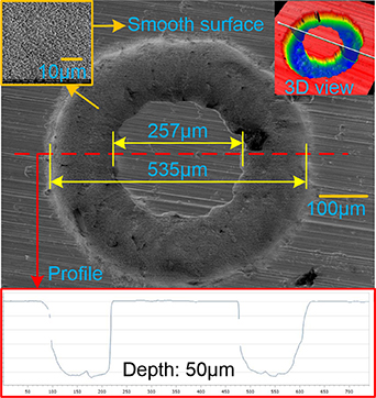
Figure 9. A circular ring micro cavity with high surface quality.
Download figure:
Standard image High-resolution imageThe die-sinking process can machine a ring channel with a consistent shape and a smaller size compared with the tool electrode end. This process can make full use of the effect of chemical removal to improve the machining quality. However, this process is subject to the scope of the chemical removal. In this research, the limited machining depth was about 50 μm. Additionally, the shape of the machined microstructure depends on the shape of the tool electrode end. Therefore, complex microstructures can potentially be machined by changing the shape of the tool electrode end. Thus, this approach has promise for application in micro manufacturing fields such as micro molds, microfluidic channels, and so on.
4.2. Scanning process for a square micro cavity
For the purpose of realizing complex micro cavities with a damage-free surface in ZrO2 ceramics using the SACE method, a layer-by-layer scanning process was experimented according to a designed path. Our previous experiments found that the feed strategy of the tool electrode is very important during the scanning process. If the feed rate of each layer in the depth direction is too small, it is likely that the tool electrode and the workpiece will not contact, resulting in an extremely low processing efficiency according to the contact effect (section 3.2). If the feed rate is too high, the contact force between the tool electrode and the workpiece is too large, which means that the tool electrode is prone to bending during the scanning process. Figure 10 shows the case in which a large contact force causes processing errors or even failure.
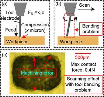
Figure 10. Bending problem of tool electrode.
Download figure:
Standard image High-resolution imageMicro-drilling experiments using the SACE process showed that maintaining a lower contact force between the tool electrode and the workpiece can improve the machining speed and consistency [17]. In order to obtain a small contact force, a tool electrode with a spring structure shown in figure 11 was designed to reduce the tool stiffness and thereby ensure a smaller contact force under the same compression amount. A guide tube was used to ensure the movement stability of the tool electrode. Thus, the bending problem of the tool electrode during the scanning process was avoided. The spring structure (figures 11(c) and (d)) effectively reduced the tool stiffness from 2 g μm to 0.004 g μm, as measured by the force sensor (figure 3) in the experimental system. The low stiffness not only ensured a micro contact force of 0.4 g of the tool electrode at a compression of 100 μm, but also ensured the stability of the scanning process after each layer feed of several hundred microns. Using this low-stiffness tool electrode with a rotation speed of 200 rpm in the scanning process, a square micro cavity (figure 12) was machined on the ZrO2 ceramic coating fabricated by a ceramic spraying process. As shown in figure 12, compared to the roughness of the original surface (9.83 μm Sa), the machined surface has a lower roughness (3.94 μm Sa). Additionally, compared with that of figure 10, the accuracy of the machined shape of figure 12 is obviously superior.
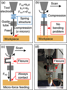
Figure 11. A low stiffness tool electrode with flexure structure.
Download figure:
Standard image High-resolution image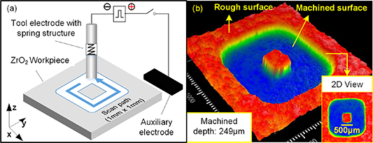
Figure 12. Scanning path and machining result of a square micro cavity.
Download figure:
Standard image High-resolution image
Unlike the die-sinking process, the scanning process has a wider range of applications for the machining of complex 3D microstructures. By reducing the contact force between the tool electrode and the workpiece and by adopting the discharge constraint strategy, the processing quality was effectively improved. This approach is suitable for application in the fabrication of micro devices made of ZrO2 ceramics. These micro devices have superior mechanical properties than those made from Si-based materials in micro-electromechanical systems (MEMS).
5. Conclusions
In order to machine micro structures without microcracks in ZrO2 ceramics using the SACE process, a spark energy action model was established to analyze the spark energy difference between physical removal and chemical removal on the workpiece surface. The spark energy acting on the workpiece surface can be adjusted by changing the electric parameters (processing voltage and pulse duration) and electrolyte film thickness. Furthermore, a SACE processing model considering the contact effect and discharge constraint was established, which provides a theoretical basis for the application of a chemical removal dominated SACE process to ZrO2 ceramics. The theoretical models were verified by typical SACE experiments on ZrO2 ceramics. The main conclusions are as follows:
- (a)The necessary conditions for achieving a damage-free surface using the chemical removal dominated SACE process are: the critical energy of physical removal Qcpr is greater than that of the critical energy of chemical removal Qccr (Qcpr> Qccr), and the spark energy Q can be adjusted to satisfy Qcpr> Q> Qccr. These conditions can explain the effect mechanism of different surface qualities from SACE experiments.
- (b)An important effect, named the contact effect of SACE on ZrO2 ceramics, was found in our experiments. This indicates that the effective removal of workpiece material can be achieved only if the tool electrode is in contact with the workpiece. The contact effect can explain why the SACE process is sensitive to the machining gap.
- (c)By applying the proposed SACE processing model in leading the chemical removal dominated process, a circular ring micro cavity with high surface quality was machined in a ZrO2 ceramic workpiece under the effects of the discharge constraint and the contact effect.
- (d)For applying the proposed models and methods for the scanning SACE process of complex micro cavities, a low-stiffness tool electrode with a spring structure was designed and used to achieve stable micro-force contact between the tool electrode and the workpiece. In this way, a square micro cavity without micro cracks was machined in a ZrO2 ceramic workpiece.
Acknowledgments
This research is supported by National Natural Science Foundation of China (Grant No. 51675302) and Independent Research Project of State Key Laboratory of Tribology of China (Grant No. SKLT2019B04).