Numerical Investigations on Material Flow During Indirect Extrusion of Copper-Clad Aluminum Rods
 Stefan Kuhnke
 Vidal Sanabria
 Felix Gensch
 Renè Nitschke
 Soeren Mueller
- 1Extrusion Research and Development Center, Technische Universität Berlin, Berlin, Germany
- 2INGWERK GmbH, Berlin, Germany
In the extrusion of clad composite materials with different flow stresses are usually used. This causes an inhomogeneous material flow which can induce sleeve or core fracture. In the present study, the material flow during indirect extrusion of copper-clad aluminum (CCA) rods was analyzed by means of experimental and numerical investigations throughout the process. In order to provide material models for the numerical analysis hot compression tests of the aluminum alloy EN AW-1080A and the copper alloy CW004A were carried out. The indirect extrusion was performed using a conical die with a semi die angle of 45° and an extrusion ratio of 14.8:1. The container was heated to 330°C, while billet, die, and ram were kept at room temperature. The extrusion trial was then modeled with the FEM based software DEFORM 2D. Cross sections were taken from the extruded rod and compared to the corresponding sections of the simulation with regard to the development of the equivalent copper cross section. As a result, the development of extrusion force and equivalent copper cross section could be clarified. The numerical investigations indicated a higher flow velocity for the aluminum core than for the copper sleeve at the bearing channel. Therefore, high tensile stresses and fractures of the copper sleeve were induced. Additionally, the validated numerical analysis made possible to determine the conditions for a successful co-extrusion of the analyzed CCA rod.
Introduction
The use of copper-clad aluminum (CCA) has greatly increased since it was introduced in 1963. Its beneficial characteristics, such as reduced costs and weight with high conductivity at the same time, make it attractive for the use as wires, cables, and bus-bars (Ahmed, 1978; Kang et al., 2002). The production of CCA profiles is mainly carried out by hydrostatic extrusion, since this process is characterized by a more uniform material flow than conventional direct and indirect extrusion (Osakada et al., 1973). However, hydrostatic extrusion is a complex and expensive process and the availability of such machines is very limited. Therefore, direct and indirect extrusion are of great interest for this application.
Many studies have investigated the optimal process parameters and initial conditions for direct and indirect extrusion of CCA by means of experimental and numerical analysis. Haghighat and Momeni-Khabisi (2014) determined the extrusion force and optimal semi die angles for the indirect extrusion process in relation to friction factor and extrusion ratio by using upper bound and finite element methods. Kang and Kwon (2002) investigated sleeve fracture and friction factor in direct and indirect extrusion. They used the Cockcroft and Latham fracture model for prediction of sleeve fracture and determined fracture strain values of 0.3–0.7, depending on lubrication conditions. For the use of carbon oil spray a friction factor of 0.25 was identified. Kazanowski et al. (2004) investigated the influence of the billet geometry and found the shortening of the core to be beneficial for the geometrical stability of the profile and to reduce the tendency for material separation at the tip of the profile. The upper temperature limit for sound indirect extrusion of CCA was found at approximately 350°C by Kwon et al. (2004). They also showed a stable extrusion process for a high extrusion ratio of 21.4:1 and an equivalent copper cross section of 0.30 of the total billet cross section. Jang and Hwang (2007) did a FE-analysis of the direct extrusion of composites regarding the plastic deformation behavior and velocity discontinuities between the used materials. They identified a tight bonding between sleeve and core as crucial for a homogeneous material flow.
In this study, the indirect extrusion of a CCA rod was carried out and modeled with the FEM based software DEFORM 2D to investigate the material flow evolution throughout the process. Thus, the flow stresses of aluminum alloy EN AW-1080A and copper alloy CW004A were obtained by hot compression tests. An extrusion trial was performed under non-isothermal conditions and with a semi die angle of 45°, extrusion ratio of 14.8:1 and an equivalent copper cross section of 0.24 of the total billet cross section. Variation of the material flow during the extrusion process could be determined by analyzing the evolution of the equivalent copper cross section in the extruded profile. Therefore, cross sections taken along the extruded composite rod were analyzed by means of digital image processing. The results of this analysis were compared to the results of the numerical investigations. Simulated state variables such as flow velocity, strain and stress were analyzed to explain the origin of sleeve fracture. Furthermore, the material flow during sleeve fracture was numerically described and validated with a longitudinal section of the extruded rod.
Experimental Procedure
Hot Compression Tests
For the development of the constitutive models applied in the numerical analysis of the extrusion process, stress-strain curves of cast aluminum EN AW-1080A and extruded and annealed copper CW004A were obtained by hot compression tests. Thus, cylinders (Ø = 10 mm, L = 15 mm) of both alloys were tested with the thermal-mechanical physical simulation system Gleeble 3800 with resistance heating from DSI. The applied strain rates were 0.01 s–1, 0.1 s–1, 1 s–1, 10 s–1 for aluminum and 0.1 s–1, 1 s–1, 10 s–1 for copper. The specimens were tested at a temperature range of 20–500°C with intervals of 50°C and a maximal true strain of 1.
Extrusion Trial
A CCA rod was indirect extruded on a 0.5 MN vertical extrusion press. An integrated load cell allowed the recording of the extrusion force during the process. Additionally, the strand exit temperature was measured with a thermocouple placed in the bearing channel of the die. The die was designed conically with a semi die angle of 45° and a bearing channel length of 4 mm. With an outer diameter of 30 mm and a bearing channel diameter of 7.8 mm the resulting extrusion ratio was 14.8:1. Previous to the experiment, the die was heated to 300°C, its polished cone surface greased with Luprit SP 19 and cooled back to room temperature. Luprit SP 19 is the trade name of a lubricant for the extrusion process of non-ferrous metals at elevated temperatures and consists of polyethylenes and graphites. Its drop point is approximately 80°C. For the manufacturing of the composite billet the aluminum alloy EN AW-1080A and copper alloy CW004A were selected for the core and sleeve, respectively. The copper sleeve with 104.5 mm in length and an inner diameter of 26 mm was produced by machining a Ø 33 mm × 5 mm extruded and annealed tube. The aluminum core with 100 mm in length and 26 mm in diameter was turned out of an extruded and annealed rod. With regard to the investigations of Kazanowski et al. (2004) the core was designed 5 mm shorter than the sleeve to improve the material flow during the non-steady beginning of the extrusion (see Figure 1). Furthermore, it was fitted with a chamfer (4 × 45°) and a centered hole (Ø 6.3 mm × 16 mm) to prevent the emerge of a full aluminum head. According to Jang and Hwang (2007) a tight bonding between core and sleeve is very important for a homogenous material flow. For that reason, both components were joined by shrink fitting with liquid nitrogen after being cleaned with soap and ethanol. Subsequent to the joining, the composite billet was machined to an outer diameter of 29.8 mm and the protruding front end of the copper sleeve was flanged to 9°. The resulting sleeve thickness was 1.9 mm and the equivalent copper cross section was 0.24 of the total billet cross section. Figure 1 depicts a digital 3D model of the billet (A), a photo of one manufactured billet (B), and a drawing with the most relevant dimensions (C). The experiment was performed in non-isothermal conditions with the container heated to 330°C, while billet, die, and ram were kept at room temperature. After greasing the container bore with Luprit SP 19 and waiting ca. 20 min for the waxes to evaporate, die, billet, and ram were inserted into the container. The ram speed was set to 5 mm/s and a CCA rod was extruded.
Figure 1. (A) Digital 3D model, (B) photograph, and (C) drawing of the manufactured billets.
Results and Discussion
Hot Compression Tests
Exemplary flow stress data of cast aluminum alloy EN AW-1080A as well as extruded and annealed copper alloy CW004A obtained by the hot compression tests is shown in Figure 2. For both materials the flow stress increases with strain and decreases with higher temperatures. The strain rate sensitivity is very low for both materials. The normalized flow stresses [σn = kf(T)/kf(20°C) × 100%] of the analyzed aluminum and copper alloys at a true strain of 1 and logarithmic strain rate of 1 s–1 as well as the flow stress ratio kf,Cu/kf,Al are illustrated in Figure 3A. An increase in the temperature to 350 and 500°C induces a reduction of the flow stress by 60 and 85% for aluminum as well as 40 and 70% for copper, respectively. This deviant development of flow stresses causes an increase in flow stress ratio from 3.2 at room temperature over 4.8 at 350°C to 6.7 at 500°C.
Figure 2. True stress-true strain curves of EN AW-1080A and CW004A: (A) at a constant logarithmic strain rate of ; (B) at a constant temperature of T = 200°C.
Figure 3. (A) Normalized flow stress of cast EN AW-1080A and extruded and annealed CW004A at a logarithmic strain rate of and true strain of ε = 1 as well as the flow stress ratio kf,Cu/kf,Al for cast and extruded aluminum in dependence of the temperature; (B) true stress-true strain curves of EN AW-1080A in cast and extruded condition at a strain rate of .
Kwon et al. (2004) suggest that high differences in flow stress between sleeve and core material cause sleeve fractures. Therefore, three measures were taken to reduce the flow stress ratio. First, the extrusion was set up with cold tools and billet as not to unnecessarily raise the flow stress ratio. Second, to even lower the flow stress ratio, a hot container was used. Thereby the sleeve is heated and softening of the copper is induced, while the aluminum core should stay relatively cold and thus relatively hard. Third, an extruded aluminum rod was used as core material. Due to the grain refinement caused by geometric dynamic recrystallization during the extrusion process the flow stress of the extruded aluminum is higher compared to the cast aluminum (Humphreys and Hatherly, 2004). Additional hot compression tests were carried out with the extruded aluminum and true stress-true strain curves were recorded. As illustrated in Figure 3B, the flow stress of the extruded aluminum is up to 33% higher.
Extrusion Trial
The extruded CCA rod can be divided into three characteristic parts which are shown in Figure 4, together with the extrusion diagram. The extrusion force (Figure 4A) initially shows the typical course of an indirect extrusion with a steep increase and a maximum of 387 kN. This maximum (I.) represents the beginning of the extrusion while a full aluminum head with a length of 10 mm is extruded (Figure 4B). The measured temperature increases linear to 125°C until the extrusion begins. This represents the loading process and is due to the heating of the die in the hot container. When the die cone is filled with billet material and the thermocouple is in contact with the extruded copper sleeve, the temperature increases fast. The maximum force is followed by the plateau of the quasi-steady state (II.), which rises slightly from 300 to 320 kN. During this phase of the process the temperature rises more slowly from 240 to 320°C and a sound composite profile of 620 mm in length is produced (Figure 4C). After a stroke of 60 mm the force plateau is replaced by uniform oscillations (III.) and the temperature starts to increase stepwise and synchronous to the oscillations. The extruded rod is characterized by multiple sleeve fractures (Figure 4D).
Figure 4. (A) Extrusion diagram and characteristic parts of the extruded composite rod: (B) full aluminum head, (C) sound product, (D) multiple sleeve fractures.
The extrusion force in the quasi-steady state is influenced by different factors. Temperature of the billet materials as well as friction between copper and die cone are the main factors in this experiment. The increase in profile exit temperature suggests an increase in billet temperature and therefore the reduction in flow stress for both billet materials. This in turn should cause a decrease in extrusion force, which is not observed. Consequently, friction must cause an opposite effect. Friction in extrusion depends not only on normal pressure, temperature, and velocity (Sanabria et al., 2015), but is also heavily dependent on lubrication. The available amount of lubricant is limited and consumed during the extrusion process. Black stripes of graphite on the extruded rod indicate the discharge of lubricant from the die cone. With reduction of lubrication the friction between copper and die cone increases and so does the extrusion force. Since the extrusion force is slightly rising, the influence of friction could be assumed to be higher than that of temperature.
To investigate the material flow throughout the process, the development of the equivalent copper cross section was analyzed by means of metallographic preparation. A total of six cross sections were taken from the CCA rod. One piece was taken 50 mm behind the tip and then every 200 mm (cross sections 1–4). Two additional cross sections (1B and 1C) were taken 100 and 150 mm behind the tip to increase the local resolution of the investigation in the non-steady state of the extrusion. The cross sections were ground and polished with SiC sandpaper and 6 μm/3 μm diamond suspension, respectively, and scanned on a flatbed scanner with a resolution of 3000 DPI (Figures 5A,C). For the determination of the equivalent copper cross section, the images were processed with the freeware GIMP (GNU image manipulation program) and ImageJ (Figures 5B,D) and analyzed with the particle analysis algorithm of ImageJ.
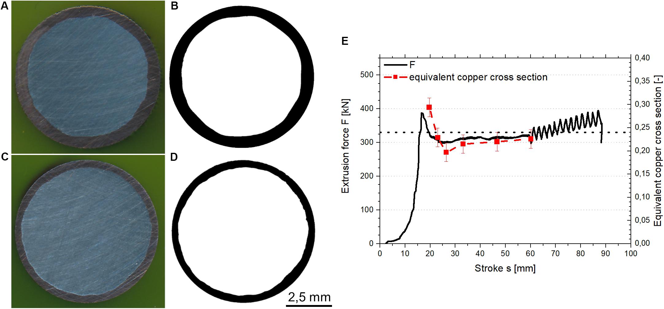
Figure 5. Illustrations of cross sections 1 and 1C: (A) scan of cross section 1, (B) digital processed scan of cross section 1, (C) scan of cross section 1C, (D) digital processed scan of cross section 1C; (E) correlation of extrusion force and development of the equivalent copper cross section.
The results of the analysis, depicted in Figure 5E together with the extrusion force, show a high equivalent copper cross section of 0.294 for cross section 1. This is due the non-steady processes at the beginning of the extrusion, as shown later in the numerical analysis. Within 100 mm this value lowers to 0.197 in cross section 1C where the quasi-steady state begins and then increases almost linearly to 0.226 in cross section 4. The dotted line marks the target value of 0.24 for the equivalent copper cross section, which is first exceeded by 22% and then underrun by up to 18%. The increase in equivalent copper cross section is based on the same two factors as the increase in extrusion force. Firstly, the increasing temperature causes the flow stress ratio to rise. Therefore, the aluminum core is more easily displaced by the copper sleeve and more copper can flow into the deformation zone and the die land. Secondly, copper in proximity to the die surface is progressively slowed down and retained in the die cone due to the increasing friction. Thus, copper slowly accumulates and the equivalent copper cross section is increased. This also contributes to the increase in extrusion force and is to be assessed as third influencing factor, though it is dependent on the interaction of the other two factors temperature and friction. Considering all three factors, the influence of friction and equivalent copper cross section together on the extrusion force is higher than that of temperature.
Numerical Analysis
In order to gain more information about the sleeve fractures and evolution of the equivalent copper cross section numerical simulations of this extrusion trial were carried out. The software DEFORM 2D was selected to perform the FE-simulations. The visco-plastic behavior of the aluminum alloy EN AW-1080A and the copper alloy CW004A was modeled using the constitutive Hensel–Spittel-equation (Spittel and Spittel, 2009)
where σs is the flow stress, ε and are plastic strain and strain rate respectively, T is the temperature and A, a1 to a8 are regression coefficients. Through empirical approximation the regression coefficients were adjusted for best match with the experimental data as shown in Figure 6. The regression coefficients are listed in Table 1. Since an extruded aluminum rod was used to fabricate the composite billet, the regression coefficients for extruded aluminum were used in the numerical analysis.
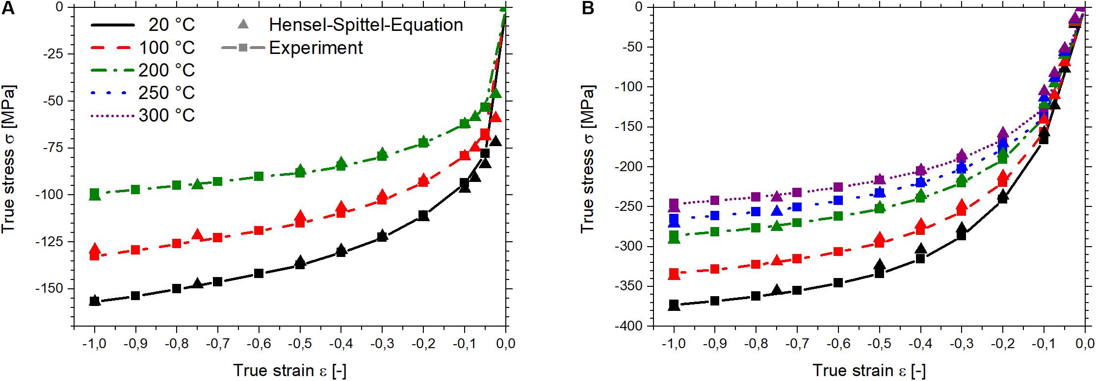
Figure 6. Comparison of the experimental flow curves and the data approximated with the Hensel–Spittel-equation at a strain rate of : (A) extruded EN AW-1080A, (B) CW004A.
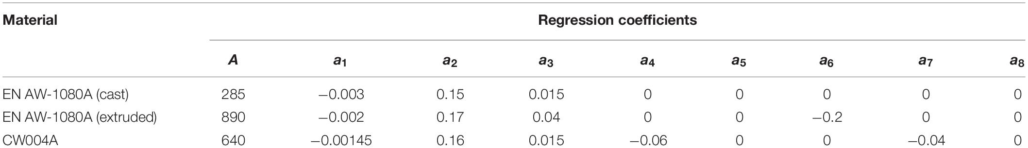
Table 1. Regression coefficients of the Hensel–Spittel-equation for EN AW-1080A and CW004A.
Figure 7 depicts the first geometrical model for the simulation. The aluminum core and copper sleeve were meshed with approximately 4,000 and up to 12,000 elements, respectively. The element type is rectangular and element size was defined relative. Mesh windows were used to increase the local resolution close to the deformation zone for a more precise calculation of the state variables. Container, die, and ram were also meshed (600, 1,000, and 500 rectangular elements, respectively) to allow a transient heat transfer between billet and tools. In contrast to the billet materials the tools were modeled as rigid bodies, which means no plastic deformation was allowed. Friction was described according to the Tresca model. The friction parameters and the heat transfer coefficients for the different material combinations and contact surfaces are listed in Table 2 (Sanabria et al., 2019). As in the extrusion trial, only the container was set at 330°C, while the initial temperature of billet and tools was 25°C. In order to reproduce the billets heating in the container during the tool loading process, the ram was placed 20 mm behind the billet. With a ram speed of 2 mm/s it moves 10 s until it contacts with the billet. This is in accordance with the experiment. As soon as the ram is in contact with the billet, ram and container move together with a speed of 5 mm/s. To prove convergence and improve mesh quality a second model with a finer mesh was created. The element size was defined absolute to enhance the control of the mesh resolution in the deformation zone and the bearing channel. Additionally, the copper sleeve was meshed with up to 15,000 elements.
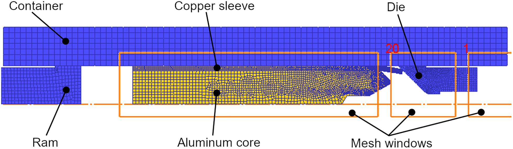
Figure 7. FE-model for the indirect extrusion of the copper-clad aluminum rod.

Table 2. Friction parameters and heat transfer coefficients for the FE-analysis of the indirect extrusion.
The experimental and simulated extrusion forces as well as the different states of material flow are shown in Figure 8. The curves of the two models with coarse and fine mesh agree very well. The only deviations are small fluctuations at the model with the coarse mesh, caused by inaccurate state variable interpolation during the remeshing steps. It is therefore assumed that the coarse meshed model is already converging. But due to the improved mesh, the second model is much more appropriate for the following analysis. The first state at a stroke of 0 mm illustrates the initial configuration. With start of the extrusion process the protruding copper is bent into the shape of the die cone and the extrusion force begins to increase. During the filling of the die cone (s = 13 mm) the centered hole in the aluminum core is closed, the copper sleeve is pushed toward the bearing channel and the extrusion force rapidly increases. At a stroke of 14 mm, when copper arrives the bearing channel and the full aluminum head is formed, the extrusion force reaches its maximum. The comparison of experimental and simulated extrusion force shows an overestimation by approximately 15% in the peak. This is probably due to the material model. Since the hot compression tests allow only a deformation to a strain of 1 the material model has to be extrapolated beyond this value. As consequence an overestimation of the flow stress for strains ε > 1 is likely. Figure 9A shows the contour plot of strain in the bearing channel during the force peak. A strain of 2 and higher is estimated by the FE-Software, which is clearly beyond the experimental flow stress data. Therefore, it is supposed that the inaccurate extrapolation of the flow stress at strains greater than 1 impairs the force prediction. The length of the full aluminum head is also influenced by the flow stress. The overestimation of the flow stress causes the aluminum to flow slower and produce a shorter full aluminum head. The calculated length is 7 mm, which is 2 mm shorter than its experimental counterpart (Figure 5B). The force peak in the extrusion diagram is followed by a steady decrease in the extrusion force. The force drop to the plateau in the quasi-steady state could not be modeled. In the quasi-steady state (Figure 8, s = 23 mm to s = 61 mm) the simulated extrusion force decreases slowly and no large changes in material flow are found. The steady decrease in extrusion force is due to the increasing temperature of the billet material. Deformation heat and heat transferred from the container reduce the flow stress of aluminum and copper and thus the force necessary for extrusion. In contrast to the experiment, this effect is not counteracted by the increase in friction. In the numerical analysis friction is modeled constant and does not increase during the process as described earlier. The simulation was stopped after a stroke of 61 mm, because the first sleeve fracture occurred in the experiment at a stroke of 57 mm. Since no fracture model was applied for the numerical analysis, sleeve fracture could not be predicted. During the non-steady beginning of the extrusion, the profile exit temperature of the experiment increases more slowly than the simulated reading (Figure 9B, stroke 13–18 mm). This is most likely due to the thermal inertia of the thermocouple, which is in tight contact with the relatively large volume of the cold die. In the quasi-steady state, the profile exit temperature is overestimated by approximately 10% and thus in acceptable agreement with the experiment.
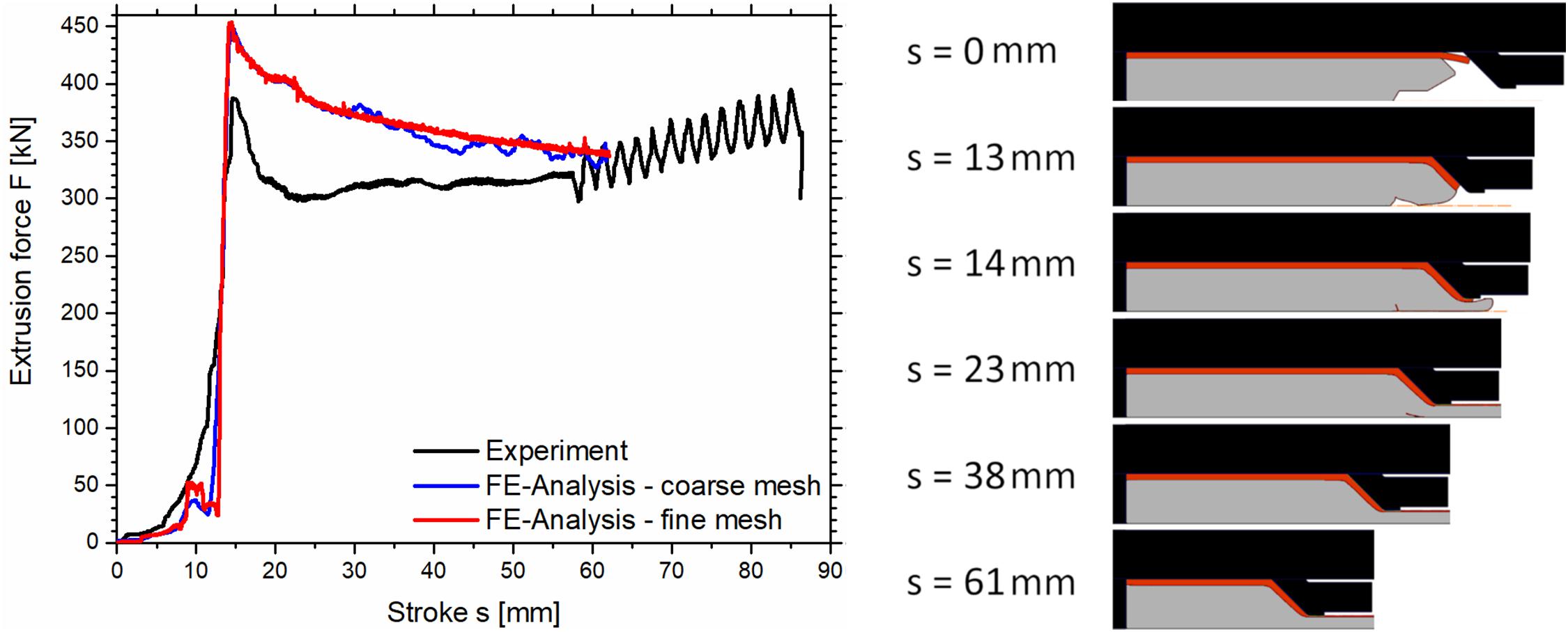
Figure 8. Extrusion diagram of experiment and FE-analysis and simulated material flow in different states of the extrusion.
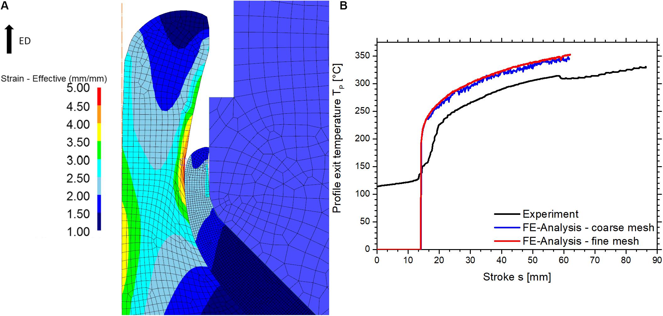
Figure 9. (A) Contour plot of strain in the bearing land during the force peak; (B) extrusion diagram of experiment and FE-analysis: temperature-stroke curves.
Since the development of the equivalent copper cross section in the experiment could be used to interpret the changes in friction in the quasi-steady state, it was also investigated in the numerical analysis. The measurements were carried out by analyzing images of 15 mm long rod sections, which were extracted from the FE-software. By binarizing the images and using the particle analysis algorithm of the freeware ImageJ, the area share of copper was determined. Subsequent, the average copper volume fraction for the 15 mm long section was calculated. The principal course of the simulated equivalent copper cross section is similar to the experiment (Figure 10), but about 15% higher at the beginning of the extrusion and only 7% higher in the quasi-steady state. Next to the overestimated flow stress this excessive copper volume is another cause for the elevated extrusion force in the simulation. Due to a higher share of copper in the deformation zone, more force is necessary for the extrusion of the CCA rod. At the beginning of the extrusion, the experimental and simulated copper volume fraction differ more than in the quasi-steady state. This is due to the non-steady processes and their impact on the influencing factors temperature and friction. The temperature is overestimated by the numerical analysis and thus the flow stress ratio is higher than in the experiment. As described earlier, this favors the increase of equivalent copper cross section. Furthermore, the friction factor is modeled constant. This implies that changes in normal pressure, temperature, velocity, and lubrication conditions are not considered in the numerical analysis. The latter also means that changes in lubrication in the quasi-steady state of the experiment are very low, since the equivalent copper cross section in experiment and numerical analysis differs only by a constant offset. This offset is probably due to an interaction of the overestimated profile exit temperature and friction factor which is set too high.
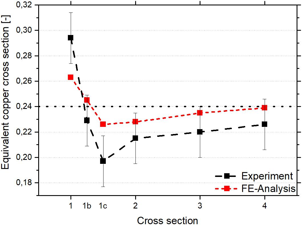
Figure 10. Comparison of experimental and simulated copper cross section.
With the information gained by means of numerical investigations, the occurrence of sleeve fracture can be explained by considering strain, flow velocities as well as stresses of aluminum and copper inside the bearing channel. Figures 11A–C illustrate these estimated state variables at a stroke of 60 mm. Points P1 and P2 were selected for the investigation of the development of the state variables in the extrusion process. The numerical results reveal a strain of 2.6–4.6 for aluminum and 3.7 for copper inside the bearing channel (Figure 11A) and the estimated velocity of aluminum is higher than copper (Figure 11B). The axial tensile stresses prevailing in the copper are up to 230 MPa, while the aluminum is exposed to axial compressive stresses of up to 145 MPa (Figure 11C). The development of strains, flow velocities and axial stresses over the process is shown in Figures 11D–F. Regarding the strain of aluminum, high values up to 4.6 are found during the beginning of the extrusion (Figure 11D). This is due to the folding and closing of the centering hole as well as formation of the full aluminum head (see Figure 8, s = 13 and s = 14). For copper an accumulation of strain to 3.9 is visible, caused by the gradually deformation during the filling of the die cone and formation of the full aluminum head. In the quasi-steady state constant levels of strain are estimated for both materials, i.e., 3.7 and 2.6 for aluminum and copper, respectively. This constancy is typical for the indirect extrusion process, since strain is only accumulated in the primary deformation zone inside the die cone (Müller, 2004). Taking into account the increase in friction in the experiment, a steady growth of strain in copper is expected in reality. The cause is increasing shear deformation in the contact area with the die. Concerning flow velocities (Figure 11E), a rapid acceleration of aluminum is noticeable with the entry of copper into the bearing channel at a stroke of ca. 13 mm. This represents the formation of the full aluminum head. In the quasi-steady state of the composite extrusion the average difference in flow velocity is 1.2 mm/s. The average axial stresses are 208 MPa for copper and −108 MPa for aluminum (Figure 11F). Except of a peak between a stroke of 23–25 mm, which is due to the folded centering hole in the aluminum core, both curves are nearly constant in the quasi-steady state of the extrusion process. The opposite sign is due to the different flow velocities. The faster flowing aluminum pulls on the copper sleeve resulting in tensile stresses. The aluminum itself is retained by the slower flowing copper and therefore compressed. As shown in Figures 11C,F high tensile stresses act on copper, which are constant in the quasi-steady state of the extrusion. These stresses can exceed critical values through small fluctuations, for example by a change in lubrication conditions, and cause a failure of the copper sleeve. Exceeding a critical flow stress ratio due to increasing temperatures is supposed to be another cause of sleeve fracture. This would cause a higher difference in flow velocities and therefore higher tension stresses in the copper sleeve. Reaching a critical strain by steady accumulation due to increasing friction can be a third cause of sleeve fracture.
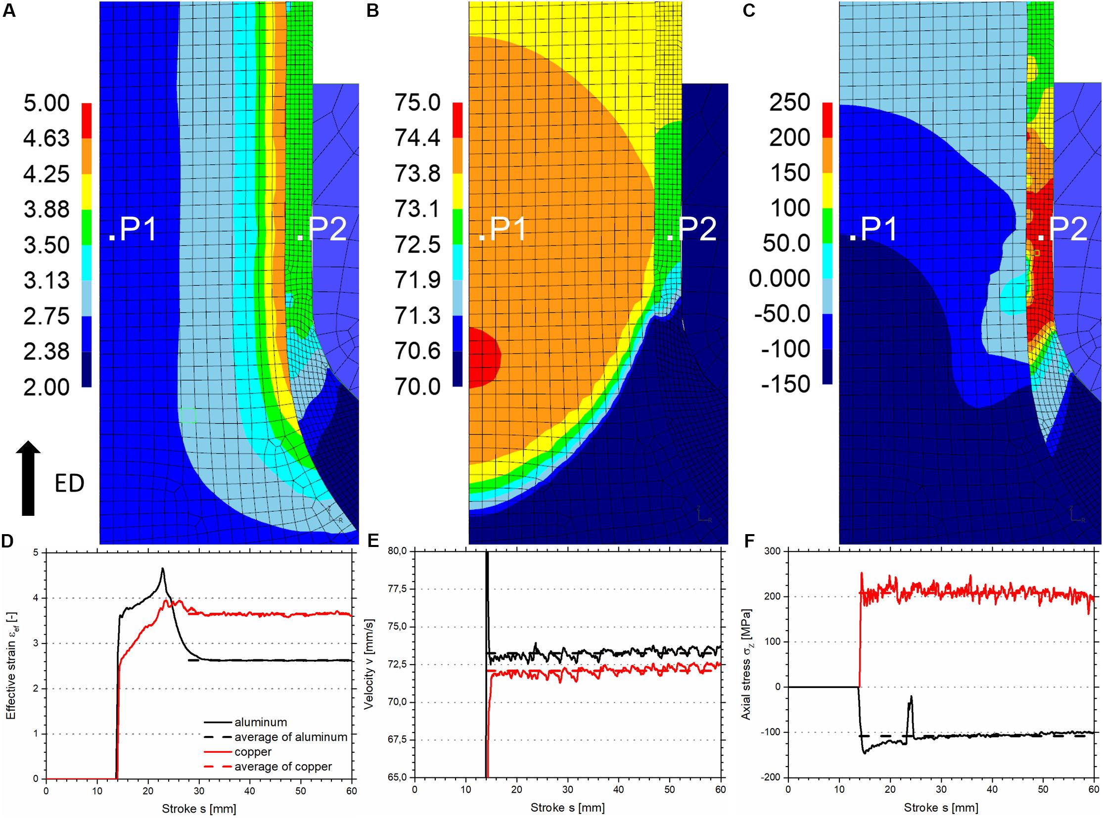
Figure 11. (A–C) Contour plots of strain, velocity and axial stress in extrusion direction; (D–F) courses of strains, velocities and axial stresses in the bearing channel at position P1 and P2.
When the extrusion diagram and rod quality were discussed, recurring oscillations in the extrusion force were observed (Figure 4A). These can be explained by correlating them with the recurring fracture of the copper sleeve. Figure 12 exemplarily illustrates the processes during the occurrence of a sleeve fracture. This sleeve fracture was artificially generated by deleting four elements of the copper sleeve (detail of Figure 12A). In the event of a sleeve fracture the faster flowing aluminum is no more retained and flows under reduced extrusion force (Figure 12A). The slow flowing copper bulges, therefore narrows the bearing channel and causes a locally increased extrusion ratio (Figure 12B). Consequently, the extrusion force increases until the copper begins to flow again and the composite extrusion is continued (Figure 12C).
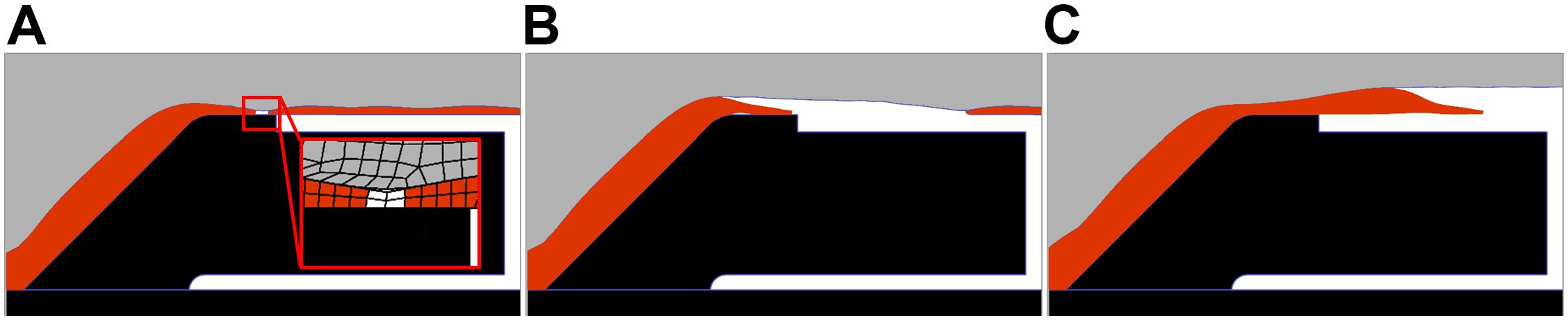
Figure 12. Illustration of the processes during the occurrence of a sleeve fracture: (A) fracture of the copper sleeve, (B) bulging of the copper, (C) re-start of the composite extrusion; color legend: gray, aluminum; orange, copper; black, die and container; extrusion direction →.
To confirm this theory a longitudinal section of a rod segment with sleeve fracture (Figure 4D) was prepared. Figure 13 shows a scan of the investigated cross section (A) and a picture detail of the simulated material flow (B). Although there are deviations between simulated and experimental thickness of the copper sleeve, the geometric shape is in good agreement.
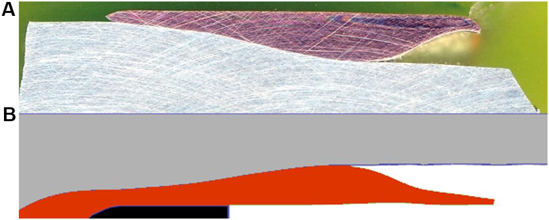
Figure 13. Overlay of an experimental (A) and simulated (B) sleeve separation; extrusion direction →.
The process of sleeve fracture and bulging of the copper is also the cause for the stepwise increase in the profile exit temperature. Since the flow velocity of copper is reduced during the occurrence of a sleeve fracture, less heat is generated by deformation due to lower strain rates and therefore the evolution of temperature stagnates. Also, contact between copper sleeve and thermocouple can be lost. With continuation of the composite extrusion possibly lost contact of copper and thermocouple is regained, the strain rate recovers and the temperature increases again. This sequence repeats with every sleeve fracture and thus the stepwise shape of the temperature curve is formed.
Conclusion
In order to investigate the material flow in indirect extrusion of CCA rods, this process was modeled with the FEM-based software DEFORM 2D. For this purpose, the stress-strain curves of aluminum alloy EN AW-1080A and copper alloy CW004A were obtained by hot compression tests using a Gleeble 3800 and the materials were modeled with the Hensel–Spittel-equation. The comparison of experiment and FE-analysis showed deviations in the extrusion force and equivalent copper cross section, especially at the non-steady beginning of the extrusion. Both could be interpreted by considering the profile exit temperature, friction between copper and die surface as well as their interaction. The assumption of a constant friction factor in the numerical analysis could eventually be stated as main cause for the deviations. The aim of future investigations must therefore be to determine the dependence of the friction factor on temperature, pressure and velocity as well as stroke and to reproduce this dependence in the FE-simulations. However, under given conditions the numerical analysis satisfactorily describes the experiment.
The investigations on material flow revealed insight into the cause and processes of sleeve fracture in CCA extrusion. Due to different flow velocities the aluminum core is exposed to compressive stresses while high tensile stresses prevail in the copper sleeve. These tensile stresses are stable in the steady state, but fluctuations, e.g., caused by changes in temperature or lubrication condition, can initiate sleeve fracture. Strain accumulation in copper due to friction shear on the die surface is assumed to be another cause. The material flow during sleeve fracture was visualized by means of FE-analysis and validated by comparison with longitudinal cross sections of the extruded rod.
In order to prevent sleeve fracture, two approaches are suggested. First, the profile exit temperature can be lowered by reducing the container temperature. This should decrease the flow stress ratio and therefore also the differences in flow velocities and stresses during the CCA extrusion. And second, improving the lubrication to maintain constant friction conditions. Likewise, this is to achieve a reduction in the differences in flow velocities and stresses.
Data Availability Statement
The datasets generated for this study are available on request to the corresponding author.
Author Contributions
FG, RN, VS, and SM contributed conception and design of the study. SK performed the hot compression tests, performed the analyses, and wrote the first draft of the manuscript. FG, RN, VS, and SK carried out the extrusion trials. SK and VS performed and interpreted the FE-analysis. All authors contributed to manuscript revision, read and approved the submitted version.
Funding
We are grateful for the financial support of the Deutsche Forschungsgemeinschaft (DFG) (Grant No. MU2963/14-1). We acknowledge support by the German Research Foundation and the Open Access Publication Fund of TU Berlin.
Conflict of Interest
FG was employed by the company INGWERK GmbH.
The remaining authors declare that the research was conducted in the absence of any commercial or financial relationships that could be construed as a potential conflict of interest.
References
Ahmed, N. (1978). Extrusion of copper clad aluminum wire. J. Mech. Work. Technol. 2, 19–32. doi: 10.1016/0378-3804(78)90012-8
Haghighat, H., and Momeni-Khabisi, H. (2014). Analysis and finite element simulation of bimetallic backward rod extrusion. Austr. J. Mech. Eng. 12, 282–290. doi: 10.7158/M13-019.2014.12.3
Humphreys, F. J., and Hatherly, M. (2004). Recrystallization and Related Annealing Phenomena. Amsterdam: Elsevier.
Jang, D. H., and Hwang, B. B. (2007). Deformation analysis of co-extrusion process of aluminum alloy and copper alloy. Key Eng. Mater. 340–341, 645–648.
Kang, C. G., Jung, Y. J., and Kwon, H. C. (2002). Finite element simulation of die design for hot extrusion process of AL/Cu clad composite and its experimental investigation. J. Mater. Proc. Technol. 124, 49–56. doi: 10.1016/S0924-0136(02)00106-1
Kang, C.-G., and Kwon, H. C. (2002). Finite element analysis considering fracture strain of sheath material and die lubricant in extrusion process of Al/Cu clad composites and its experimental investigation. Intern. J. Mech. Sci. 44, 247–267. doi: 10.1016/S0020-7403(01)00102-3
Kazanowski, P., Epler, M. E., and Misiolek, W. Z. (2004). Bi-metal rod extrusion – process and product optimization. Mater. Sci. Eng. A 369, 170–180. doi: 10.1016/j.msea.2003.11.002
Kwon, H. C., Jung, T. K., Lim, S. C., and Kim, M. S. (2004). Fabrication of copper clad aluminum wire(CCAW) by indirect extrusion and drawing. Mater. Sci. Forum 449-452, 317–320.
Osakada, K., Limb, M., and Mellor, P. B. (1973). Hydrostatic extrusion of composite rods with hard cores. Intern. J. Mech. Sci. 15, 291–307. doi: 10.1016/0020-7403(73)90011-8
Sanabria, S., Müller, S., and Reimers, W. (2015). Friction modelling in long bearing channels during multi-hole extrusion of aluminium alloy. Mater. Today Proc. 2, 4820–4828. doi: 10.1016/j.matpr.2015.10.021
Sanabria, V., Gall, S., Gensch, F., Nitschke, R., and Mueller, S. (2019). “Backward extrusion of bimetallic aluminum-copper alloys at room temperature,” in Proceedings of the 22th International Conference on Material Forming (ESAFORM), Spain.
Keywords: copper-clad aluminum, indirect extrusion, material flow, sleeve fracture, flow velocity, axial stress
Citation: Kuhnke S, Sanabria V, Gensch F, Nitschke R and Mueller S (2020) Numerical Investigations on Material Flow During Indirect Extrusion of Copper-Clad Aluminum Rods. Front. Mater. 7:157. doi: 10.3389/fmats.2020.00157
Received: 12 February 2020; Accepted: 01 May 2020;
Published: 09 June 2020.
Edited by:
Alberto Corigliano, Politecnico di Milano, ItalyReviewed by:
Yongxing Shen, Shanghai Jiao Tong University, ChinaBo Li, Case Western Reserve University, United States
Copyright © 2020 Kuhnke, Sanabria, Gensch, Nitschke and Mueller. This is an open-access article distributed under the terms of the Creative Commons Attribution License (CC BY). The use, distribution or reproduction in other forums is permitted, provided the original author(s) and the copyright owner(s) are credited and that the original publication in this journal is cited, in accordance with accepted academic practice. No use, distribution or reproduction is permitted which does not comply with these terms.
*Correspondence: Stefan Kuhnke, stefan.kuhnke@strangpressen.berlin