Concrete Silos: Failures, Design Issues and Repair/Strengthening Methods


Department of Civil Engineering, University of Patras, 26500 Patra, Greece
Appl. Sci. 2020, 10(11), 3938; https://doi.org/10.3390/app10113938
Submission received: 17 May 2020
/
Revised: 28 May 2020
/
Accepted: 2 June 2020
/
Published: 5 June 2020
(This article belongs to the Section Civil Engineering)
Abstract
:The review article investigated failure, design issues, repair and strengthening of reinforced concrete (RC) silos, primarily in agricultural set-ups. The durability of RC structures was influenced by the nature of the bulk solids, materials used in the reinforcement of the structures. Traditionally, high-grade steel has been used in silo wall reinforcement because it is affordable and readily available. However, it is susceptible to corrosion. In contrast, fiber-reinforced polymers (FRP) have better mechanical properties (tensile strength, elastic modulus, and Poisson’s ratio) and are not corroded. Additionally, there are limited scalable and facile methods for commercial production. The low ductility elevates the risk of brittle fracture in external pre-stressing concrete repair/strengthening. Beyond the material factors, the existing silo design codes such as BS EN 1991-4:2006, Australian Standard AS 3774-1996, and American Society of Agricultural Engineers ANSI/ASAE EP433 DEC1988 (R2011), and American Concrete Institute ACI 313-97 are limited by simplified characterization of loading/unloading scenarios and exclusion of specific hopper geometries and configurations. The funnel and mass flow scenarios and accumulation of bulk materials contribute to silo failure. In brief, the present repair/strengthening strategies (external pre-stressing, insertion/removal of inserts, shear columns, and FRPs alternatives to steel) do not adequately address the diverse variables that elevate the risk of material failure.
1. Introduction
The review article investigates the performance of the reinforced concrete (RC) silo structures, including the engineering and material factors that result in structural failure. The concrete silos of interest are used in the storage of bulk grains after farm harvesting. The silos used in the storage of non-agricultural produce were excluded from this study. The reinforced concrete silos under consideration are primarily made of concrete reinforced with steel bars/rebar, and alternative materials, especially at the foundation and hopper wall sections. The current issues facing traditional RC silos include bulk solid abrasion, which exposes the steel bars to the environment leading to corrosion. Additional challenges include design code limitations, poor design and failure due to periodical loading and unloading. The possible solutions include the reinforcement of concrete with materials, which are not susceptible to corrosion such as fiber reinforced polymers, the revision of existing design codes and adoption of better designs. The outcomes of this review have significant implications for RC silo engineers and operators, because they demonstrate the limitations of standard methods of construction and maintenance. Additionally, the findings provide tangible solutions for mitigating the risk of failure.
The main loading and unloading scenarios of interest are hopper geometry (vertical end walls with a wedge, square pyramid, and single symmetrical cone), the filling and the discharge conditions (patch loads, funnel flow, mass flow, pipe flow, mixed flow, extended flow, and silo quacking), thermal ratcheting, internals, external equipment, grain swelling, and effect of gas pressure [1]. The specific cases of failure are investigated to determine the contribution of design to structural failure.
Each factor that contributes to the failure of reinforced concrete silo structures is considered in Section 2 and Section 3. The main factors under considerations include the errors in the design phase (attributed to the inadequacy of the international design codes) and the challenges in maintaining the concrete walls/inappropriate care in the construction phase are reviewed. Other factors of interest include the adoption of adjustable formwork in the building and the differences in the temperature gradients linked to bulk grain storage [2]. Moreover, the lack of thermal protection coating or the availability of inadequate thermal protection; moisture accumulation and contact between the concrete wall and the vibrator steel bars are investigated. The investigation of the thermal protection also informed the analysis of improper spacing between the horizontal and vertical steel bars, the inclusion of an inadequate number of reinforced steel bars. The latter factors trigger wall shrinkage, non-symmetric pressure linked to poor design, large temperature gradients due to weather changes, wind-induced horizontal pressure changes, and pressure induced by the incorporation of inserts. Additionally, the factors are responsible for wall stiffness linked to reinforced concrete additives, circular hopper bending attributed to the eccentric withdrawals, variations in the strength and the diameters of the steel reinforcements, uneven distribution of the cement strength, wall bulking due to inadequate structural support, corrosion, concrete carbonization, and cracking. The imperfections in the steel reinforcements caused by poor adhesion, inclusion of incorrect materials are reviewed. In addition, design factors that cause poor foundation, changes in design during construction, explosions, disregard of the possible flow patterns during the design phase and inclusion of poor quality lap slices [2] are analyzed to determine the extent to which they influence silo structural strength.
Both American and European design codes namely American Society of Agricultural Engineers ANSI/ASAE EP433 DEC1988 (R2011), American Concrete Institute ACI 313-97, British Standard BS EN 1991-4:2006, Australian Standard AS 3774-1996 [1] are reviewed to determine whether conformity to standards could help reduce cases of failure associated with silos. The study is important because there are no globally accepted standards and timelines for reinforced concrete repair and strengthening of the reinforced concrete circular silos; this has elevated the susceptibility to failure [3]. The research also considers the material and structural factors from the perspective of emerging technologies such as fiber-reinforced polymers, carbon fibers, carbon nanotubes, and new concrete repair methods (such as laser interferometry) [4] to augment the durability of the silo structures [5,6]. The review article focuses on four aspects, namely the design, construction (failure), usage/maintenance (repair), because these variables predict the sustainability of reinforced concrete silo hoppers [7].
In the 20th century, construction engineer observed that silo construction poses the greatest risk of failure compared to other construction projects. Such an assessment was accurate, considering that nearly 30 percent of concrete silos failed [7]. The main question is if advances in materials science and nanotechnology and development of new and novel forms of concrete reinforcements would help to mitigate the risk of silo failure—new materials that have been developed in the recent past include CNTs and graphene, which were discovered in 1991 and 2004, respectively [8]. Both materials have proven effective in the reinforcement of concrete structures. From the researcher’s point of view, the material advances only address part of the problem because there are other factors that are associated with the failure of reinforced concrete structures; these include the disregard of the design codes, the pressure associated with the incorporation of the inserts, the incorporation of sub-standard materials, inaccurate estimation of the flows [7]. The engineering and material factors that lead to failure are discussed in the next section.
2. Failure of Reinforced Concrete Silos
The failure of reinforced concrete silos is attributed to material, design, design codes, and durability issues [9]. In the present context, the term durability denotes the ability of a material or structure to maintain the structural, aesthetic, functional, and mechanical properties over its useful life. The durability of RC silos and other concrete reinforced structures, can be predicted by the S ≤ R relationship where R is the acoustics, fire durability, crack width limits, limit deflections, and construction resistance, construction resistance. The symbol S represents the loading, which influences thermal, chemicals, acoustics, movement of metal reinforcements, and the loading variables [2]. If the conditions outlined in the above equation are maintained, there is a marginal risk of structural failure over time T. However, periodical loading and unloading in silos contribute to stress on the building structures. Considering that each material has a defined number of cycles to failure, an increase in the frequency of loading and unloading elevated the risk of failure. Even though high durability is desirable, the properties might be adjusted through the modification of the computational resistance parameters in the Serviceability Limit State (SLS) and the Limit State Design (LSD) [2]. In each of the two states, the S and R parameters could be modified. On the downside, the modification of these parameters has to take into consideration other material and non-material factors such as the physical properties of the bulk solids, and the type of flow (mass and funnel flow).
Apart from durability, the integrity of the structure is also influenced by secondary variables such as filling and discharge pressure [3], wind, and thermal actions linked to ambient fluctuations in the temperature [10]. The filling and discharge pressure in the silo, which is predicted by the flow patterns (mass flow and funnel flow), determines the risk of silo wall rotation and displacements and other forms of structural deformation [11]. In brief, the filling and discharge pressures are the most important secondary factors in the design of silos. The contribution of each of these variables to the failure of reinforced concrete structures is reviewed in the following subsections; Section 2.1 investigates the role of material factors on reinforced concrete silo failure.
2.1. Material-Related Factors
Materials infused into the reinforced concrete silos predict structural integrity, durability, ability to withstand environmental degradation (water and acid-induced corrosion, bacterial corrosion), and the repair timelines. Various materials that are ideal for the construction of concrete structures including self-healing polymers [12], carbon fibers [13], biodegradable and fiber-reinforced polymers [14,15,16], cement pastes infused with agricultural waste and renewable feedstock [17,18], carbon nanotubes, fiber-filled polymer hybrids [19]. The selection of suitable materials for silo construction applications is influenced by key factors including the mechanical properties (tensile strength, modulus of elasticity, and flexural strength) [20,21], material variability, thermal ratcheting, ratcheting, and the wall loading scenarios to ensure that the filling and discharge pressure (kN/m2) does not exceed the limits of the material [3] and the internal resistance of the bulk materials [10]. The material variability [22], loading, and unloading factors are reviewed in the next section.
2.2. Material Variability and Loading/Unloading Factors
According to research, there are diverse wall loading scenarios for reinforced concrete silo structures, depending on whether the materials are used in the construction of the hopper walls or barrel walls [23]. Based on the wall loading assessment, materials with advanced mechanical properties were necessary for the cylinder and hopper walls. An experiment conducted on a silo handling bulk maize noted that the loading and unloading impacted the structure of the silo shows that the optimal accumulation of vertical pressure in the silo bottom was recorded from day 1 to day 40. The decline in silo pressure due to bulk grain unloading was noted from day 40 to day 58, a trend that was also correlated with the decline in the column strength. A significant decline in column strength was noted from day 40 to day 58 [24].
The load and unloading scenarios listed in Table 1 are influenced by thermal ratcheting—a condition that has been observed in both metallic and reinforced concrete silo; it is characterized by the expansion and contraction of the hopper walls in line with the fluctuations in the daytime and nighttime temperatures. Lab experiments have shown that the temperatures may vary by up to ±35–40 °C, leading to variations in the internal frequency angles [11]. Each temperature cycle contributes to the buildup of pressure and stress on the wall structures leading to failure [1,11]. Even though the phenomenon is highly common in metallic silos (metals have a higher coefficient of thermal expansion), thermal ratcheting has also been observed in reinforced concrete silos. The coefficient of thermal expansion for concrete varies between 6 × 10⁻⁶ and 8 × 10⁻⁶ 1/°C in the transverse and longitudinal directions, respectively [25]. Even though thermal ratcheting is a significant problem for reinforced concrete structures, it has been under-appreciated in silo design codes [1]. The exclusion or disregard of thermal ratcheting in the design of modern silos increases the risk of structural failure, as evidenced by the collapse of a 9000-ton silo in South West US [11]. The materials used in reinforced concrete structures are reviewed in Section 2.2.
The four globally accepted silo design codes are British Standard BS EN 1991-4:2006, Australian Standard AS 3774-1996, American Society of Agricultural Engineers ANSI/ASAE EP433 DEC1988 (R2011), and American Concrete Institute ACI 313-97 [1]. However, the Australian Standard AS 3774-1996, and American Concrete Institute ACI 313-97 do not provide estimates for thermal ratcheting on silo—a factor that elevates the risk errors in construction. Additionally, the estimates for thermal ratcheting effects outlined in the American Society of Agricultural Engineers ANSI/ASAE EP433 DEC1988 (R2011) are based on lab experiments and models of steel silos rather than in-situ data derived from large physical silos. Additional constraints associated with the design codes was the inclusion of the Janssen’s Cd parameters to cover for the inaccuracy in the estimation of the bulk grain discharge pressure [26]. Even though the parameter helped to ease the pressure during the solid bulk discharge, it is inadequate because the design codes largely disregard the asymmetric flow patterns.
2.3. Materials for Reinforcing Concrete
Considering that thermal ratcheting in silos was influenced by the thermal conductivity of the materials, a primary question is whether modifications in the composition of the reinforced concrete would help to mitigate the impact of thermal ratcheting and compensate for the design code limitations. From the researcher’s point of view, the coefficient of thermal expansion, and thermal ratcheting by extension in reinforced concrete can be tailored through the use of different reinforcing materials. The observation is based on the wide variability of the coefficients of thermal expansion in steel, concrete, glass fiber reinforced polymers (GFRP), Amarid Fibre reinforced polymers (AFRP), basalt fiber reinforced polymers (BFRP), and carbon fiber reinforced polymers in Table 1 [25]. Based on the evaluation of the data, it can be deduced that replacing steel reinforcements in the concrete with Amarid Fiber-reinforced polymers and basalt fiber reinforced polymers (BFRP) would help to reduce the coefficient of thermal expansion and thermal ratcheting; this is because the coefficient of thermal expansion for steel was fivefold higher relative to the BFRP and the AFRP.
The alternative materials are also suitable from a material strength standpoint because the tensile strength of steel is lower relative to the new materials; steel, concrete, glass fiber reinforced polymers (GFRP), Amarid Fibre reinforced polymers (AFRP), basalt fiber reinforced polymers (BFRP), and carbon fiber reinforced polymers (CFRP). The material solutions which address the risk of thermal ratcheting in silos do not involve a tradeoff with the mechanical strength of the structure; the tensile strength of steel is lower relative to the alternative reinforcement materials [25]. The need to replace steel (tensile strength (TS) = 599) with glass fiber reinforced polymers (GFRP) (tensile strength (TS) = 883), Amarid Fibre reinforced polymers (AFRP) (tensile strength (TS) = 1224), basalt fiber reinforced polymers (BFRP) (tensile strength (TS) = 1021), and carbon fiber reinforced polymers (CFRP) (tensile strength (TS) = 1304) [25] is also informed by the economic implications of corrosion on the construction industry. In addition to GFRP, BFRP, AFRP, and CFRP, other materials have been proven effective in reinforcing concrete silo structures such as bamboo [27]. The direct cost of corrosion-induced damage to concrete reinforced structures in the US exceeds USD 22 billion [28].
The data presented in Table 2 show the various composition and strength grade of different concrete used for concrete silo construction; it is evident that fiber reinforcement had an upper limit. Optimal tensile strength was observed after increasing the fiber concentration to 3.0–4.5. A further increase did not translate to an improvement in tensile strength. The values in Table 3 show that there is a linear relationship between mechanical properties and chemical composition.
Even though the replacement of steel reinforcements with alternative materials with high tensile strength is viable from a theoretical and economic perspective, steel is the material of choice in concrete reinforcements [31,32,33]. The preference for steel is informed by the availability of raw materials and cost. Steel is both cheap and readily available [28], and new methods have been developed to mitigate the risk of corrosion, including non-destructive methods, passivation techniques, and embedding fiber-optic point sensors within the concrete structure. The complexity of steel reinforcements underscores the need to develop affordable and alternative materials that can be produced via facile and scalable routes. Additionally, it is necessary to ensure that both tensile strength and thermal coefficients are optimized in FRP materials in concrete structures. From an abstract perspective, the development of new materials might be a practical short-term solution due to market-related factors. However, the thermal expansion co-efficient related factors could be resolved by the proposals listed in the EN 1991-1-5 silo design codes. The recommendations propose the following:
- The design and material selection process should take into account the climate-induced thermal effects (such as solar radiation and air temperature), which impact temperature distribution and silo operating conditions.
- The engineers should define the uniform temperature component in line with the ambient air temperature (operating temperature).
- Solar gain-based stepped temperature component should be estimated at 15 °C unless otherwise stated.
- The differences between the inside fillings and the ambient air are considered as the difference between the inner and the outer surfaces, after accommodating the impact of insulation.
- The temperature-related estimates and assumptions should be based on hot summer days (to accurately determine the effect of solar gains), and an empty silo.
Impact of Silo Materials on Quality of Stored Grains and Reverse Effects
Beyond impacting the material properties and the failure risk, the type of material used in the construction of the silo predicts the quality of grain (risk of aflatoxins growth, protein content, moisture accumulation/loss, crude fiber content, and oil content). The impact of material-related factors on the quality of grains is more pronounced in traditional, small scale silos constructed by farmers. Jayachandran et al. (2019) note that cost factors have often informed the selection of materials such as termite mound clay [27] and reinforced clay, which is inappropriate for sustainable silo structures based on susceptibility to brittle fracture. In addition, clays are permeable to water-induced deformation and have limited structural integrity compared to reinforced concrete. The risk of moisture transfer is influenced by the chemical composition of the clays—Kaolinite and illite, Mn, and Fe oxides are the primary constituents [34].
A comparative review of reinforced concrete, steel, and termite mound clay and steel silos showed that the silos made of clay were highly susceptible to moisture transfer compared to the reinforced concrete structures. In particular, the moisture content increased by 2.6%, increasing the risk of moisture-induced degradation of the stored grains. Further experiments confirmed that grains stored in termite mound clay silos recorded the highest decline (39%–54%) in ash content, starch content, crude fiber content, oil, and protein content, as shown in Table 4 [35]. In brief, reinforced concrete silos are superior, given the negative effect of termite mound clay silos on the quality of the stored grain. However, the selection of sustainable materials for concrete structures involves cost tradeoff—the cost of reinforced concrete structures is higher compared to termite mound clays. The risk of moisture accumulation is also predicted by the material properties of the bulk solids; the storage of rapeseeds in reinforced concrete silos has been associated with a higher risk of dampness [36] and structural failure of the hopper walls. In contrast, non-food bulk solids such as ground gypsum have a lower moisture content, and there is a minimal risk of dampening. On the downside, the low risk of dampening is offset by high bulk density (1174 kg/m3) [37], which is about 1.5 times the bulk density of wheat (761 kg/m3) [38]; this demonstrates that no solid bulk material is ideal—different bulk solids pose distinct risks on the structural integrity of the wall structures.
2.4. Reverse Effects of the Stored Bulk Solids—Corrosion, Thermal Gradient, and Differentials
The impact of materials on the quality of grains stored in silos has a ‘reverse effect.’ For example, the accumulation of moisture on the grains triggers bacterial and fungal activity, which may trigger bacterial-induced corrosion of steel-reinforced concrete structures. In other cases, pore-water pressure can result in hoop compression [39]. Microbial induced corrosion of steel and reinforced concrete structures by heterotrophic bacteria and fungi [40], and sulfate-reducing bacteria [41] such as Pseudomonas sp. [42] via cathodic depolarization is well documented in the literature. A pertinent issue is whether the reverse effect linked to microbial corrosion could be mitigated by post-harvest treatment of the grains.
Apart from inducing corrosion, high moisture (and dampness in the bulk solids) content is a risk factor for cohesive arching and caking [36]. Bywalski and Kamiński noted that dampness triggered the collapse of a rapeseed meal silo through caking and arching. However, structural failure is only possible if the silo walls have been subjected to dampness for an extended period because caking and arching are gradual processes. In addition to the risk of corrosion, different grains have different Poisson’s ratio, coefficient of wall friction, internal bulk density, internal angles of friction, cohesion, and interval voids ratio. The relationship between the internal voids ratio and structural properties is predicted by the hypo-plasticity theory, which indicates that the silo wall stress rate is a function of both the void ratio and the strain rate [43].
Each of the listed parameters contributes to the stress on the internal walls of the silos [38]. Considering that wheat and maize have higher angles of internal friction (ϕ) compared to soya beans (30, 31 versus 26, respectively) [38], silos should be designed to handle specific grains or built to higher standards to withstand the internal pressures associated with the incorporation of different grains. The standards should also factor variations in experimental data—Lapko, Gnatowski, and Prusiel [10], and Rotter, Goodey, and Brown [38] have published different values for the internal angle of friction for wheat (28 and 39, respectively). From a design perspective, the extent of variability is significant and may result in design errors or even failure. The risk of failure due to the under-appreciation of the properties of the bulk solids is high because scholarly research illustrates that properties of the stored bulk solids are not always taken into consideration during the design process, as confirmed in the failure analysis of cylindrical wall silos [44].
Matiaskova, Bilcik, and Soltesz noted that the properties of stored bulk solids had an overbearing effect on the propagation of cracks in cylindrical silos [44]. However, crack initiation is dependent on the following criteria; (i) the optimal plastic strain should be positive; (ii) the tensile equivalent plastic strain should be greater than zero [43]. The bulk solids caused a temperature gradient at the interface with the concrete walls. Under standard conditions, the cement plaster in the inner walls acts as an insulation barrier that facilitates the diffusion of heat to the concrete walls leading to a slowdown in the thermal flow gradient and temperature differentials. However, above the surface layer of the cement plaster, extreme temperature changes render the plaster insulation ineffective, leading to the propagation of cracks.
The main concern is the paucity of data on additive materials that address the temperature gradient barriers. However, practical solutions could be inferred from concrete materials used in other applications; models of temperatures flows confirmed that the cement additives impacted the temperature gradient [45]. The thermal conductivities of iron oxide additives (Fe2O3), aluminum oxide, silica, and calcium oxide were 0.3–0.37, 12–38.5, 1.3–1.5, 30.1 W/mK. In contrast, the thermal conductivity of Portland cement is 0.2–3.63 W/mK. Based on these data, the inclusion alumina as a cement component might contribute to the propagation of the cracks due to higher thermal conductivities. The impact of thermal conductivities/temperature differentials on RC silos containing cement as the bulk material [46]. The data illustrate that temperature has to be taken into consideration in silo design.
2.5. Material Design Factors and the Failure of Reinforced Concrete Structures
The case studies of failed concrete silos have demonstrated the need for careful selection of construction materials. Carson noted that the use of bolts with unsatisfactory tensile strength was one of the key factors that contributed to the failure of RC silos [7]. Similar to the observations made by Carson [7], Sagarnaga [47] observed failure in silos due to improper material design factors that led to concrete surface wear.
Impact of Bulk Grain Abrasion on the Hopper Wall Materials
The wear and tear of the silo walls caused by bulk grain abrasion is an issue of concern considering that it reduces the cross-sectional area of the walls; it may also result in the exposure of the reinforcement bars, which might, in turn, trigger corrosion caused by changes in relative humidity or moisture accumulation on the bulk grains [47]. The risk of corrosion attributed to the bulk grain materials is most pronounced in concrete silo structures reinforced with special aging steel and carbon steels [48].
The accumulation of moisture in the bulk grain is influenced by the type of bulk grain stored—previous research evidence demonstrated dampness in rapeseed meal stored in bulk silo structures [36]. In other circumstances, moisture accumulation resulted in caking and arching. On the downside, the properties of bulk solids and their effect on abrasion have been under-investigated. The observations are consistent with Horabik and Molenda [49], who noted that “bulk solid materials were of the least understood areas associated with solid processing plants.” According to the Janssen formula in Equation (1), the lateral and vertical pressures caused by bulk grains is dependent on silo diameter (D), acceleration of gravity (g), coefficient of wall friction (μ), and the Johansen’s constant (k), depth of grain in the silo (z), σx and σz lateral and vertical pressure, respectively.
The limited scholarly data relevant to the subject could be attributed to the impact of other interrelated factors such as the moisture content, flow type, gravity, density, compactness, and the model materials [49,50]. The bar graph in Figure 1 shows that there was a positive correlation between the moisture content of the bulk solid and the coefficient of friction for wheat. The moisture content of 20% translated to the highest coefficient of internal friction.
The patterns observed in Figure 1 are consistent in other cereals, namely corn, oats, and barley, as shown in Table 5. However, in the case of corn, a saturation point was achieved at 27%, after which any further increase in the moisture content did not translate to a higher friction coefficient. The pressure ratios derived using Jaky and Euro-code designs had an undefined relationship with the angle of internal friction and the moisture content. Based on these data, the wearing of the internal walls of silo hopper structures can be mitigated by controlling the moisture content of the bulk solids [49]. Alternatively, the liners and sacrificial plates [47] could help to mitigate friction in silo structures holding barley, corn, and other grains.
The impact of bulk grain abrasion-induced concrete surface wear in silos can be mitigated. However, the mitigation of these risks is fundamentally dependent on the determination of the types of bulk solids that would be stored in the silos. For silos constructed to store specific types of bulk solids, the risks could be mitigated by the insertion of the sacrificial plates and the liners [47]. On the downside, it might not be possible to mitigate the risk of bulk grain abrasion in multi-purpose silo structures during the design phase. The lack of complete information concerning the intended purpose of the silos has significant consequences in the course of the useful life of the silo structure. In brief, the periodical wear and tear of the hopper walls could have catastrophic effects on the general integrity of the silo. On the downside, these factors have been under-appreciated in the silo design codes. A review of the four commonly used design codes namely the American Society of Agricultural Engineers ANSI/ASAE EP433 DEC1988 (R2011), American Concrete Institute ACI 313-97, British Standard BS EN 1991-4:2006, Australian Standard AS 3774-1996 [1] confirmed that the issue of bulk grain abrasion was excluded. The only related conditions considered in the codes were the flow types, loading, and discharge. On the downside, addressing material-related and bulk grain-related factors remains a challenge considering that that various contractors and suppliers are involved in the construction of the silos. The risks could be mitigated by working with qualified suppliers, regular inspections, and periodical review and inspections of the silo structures before the completion of the construction.
2.6. Failure Due to Foundation/Soil Factors
Soil Effects
Poorly drained and less porous soils elevate the risk of crack formation as a result of significant heaving. Silos constructed in areas with clay soils have a greater risk of foundation failure considering that clay has a high water retention capacity, which in turn results in the expansion of the soil once the water freezes [51]. The load-bearing capacity of clay soils can be calculated using the formula in Equation (2), where the symbols qa, Nc, C, and P denote the permissible bearing capacity, shape factor, the mean shear strength of the soil, footing level overburden pressure [52].
Drained soils have a lower concentration of axial and hoop forces as shown in Figure 2 compared to un-drained soils owing to the presence of excess pore pressure [39]. Based on this evidence, silos constructed in poorly drained silos would require higher structural reinforcement to offset the pressure linked to the bulk solid materials and the hoop and axial forces [39]. Additional risk of foundation emanates from foundation stiffness, which is a risk factor for foundation failure [39]. The risk of failure due to the presence of poor soils and foundation issues can be addressed through the adoption of basic precautionary measures, which include reinforced footing and concrete foundations to offset the circumferential loads at the base of the silos, soil pressure and bending stresses [52]. Alternatively, the silo should be centered on footings to facilitate equal distribution of the load/weight. The building precautions proposed by Bozozuk are consistent with Martins, Figueiredo, Martins, and Peixoto, who proposed the reinforcement of the foundation using RC shell structure [53]. In brief, the soil effects should not be disregarded under any conditions. The design issues in reinforced concrete are discussed in Section 3.
3. Design Issues in Reinforced Concrete Silos
The design of sustainable RC silos remains a concern owing to the gaps in the body of knowledge. The existing standards lack key information and provide marginal guidelines for engineers and designers [54,55], and are grounded on the simplified characterization of the design scenarios. Chen [56] notes that the design limitations could also be correlated with the fact that the existing body of knowledge had focused on small silos; scholarly evidence concerning hoppers larger than 20 m in diameter was limited. The utility of the existing design codes namely American Society of Agricultural Engineers ANSI/ASAE EP433 DEC1988 (R2011), BS EN 1991-4:2006, Australian Standard AS 3774-1996 and American Concrete Institute ACI 313-97 [24] and China’s code GB50077-2003 [57] are reviewed in the subsequent sections.
3.1. Design Factors
Even though there are multiple design factors of interest in the construction and maintenance of concrete silo structures, the principal factors that have the most profound effect on silo failure are silo design codes, hopper design geometry and configuration (single or grouped), and mass flows (mass flow, funnel flow and expanded flow); these variables are reviewed in Section 3.1.1, Section 3.1.2 and Section 3.1.3.
3.1.1. Silo Design Codes
Silo designs are fundamentally dependent on models and building codes such as the British Standard BS EN 1991-4:2006, Australian Standard AS 3774-1996, and American Society of Agricultural Engineers ANSI/ASAE EP433 DEC1988 (R2011), and American Concrete Institute ACI 313-97 [24]. On the downside, the models are based on a simplified characterization of the actual loading and unloading pressures at the bottom and on the wall of the silo hoppers. In brief, there is a marked difference between modeled data and the real pressures observed during real loading and unloading of grains. Even though the oversimplification is unjustified because it increases the risk of failure, Ooi, Pham, and Rotter argue that the exclusion of rigorous deductive processes is validated because it helps to maintain conservatism and the maintenance of safe margins of error [57].
The ability to maintain safe margins of errors proposed by Ooi, Pham, and Rotter argue [57] could be a challenge because different countries conform to different standards. Western countries such as the US, UK, Canada, and Australia have adopted the American Society of Agricultural Engineers ANSI/ASAE EP433 DEC1988 (R2011), American Concrete Institute ACI 313-97 [24], EN 1991-4:2006, Australian Standard AS 3774-1996. In contrast, Asian countries have developed their own silo design codes such as GB50077-2003 [56]. The latter silo code design is inherently limited compared to Western standards because of the following reasons: One, it provides an inaccurate assessment of the Rankine active earth pressure, and the general calculation of the wall pressure in silo structures. The GB50077-2003 [56] formula for Rankine active earth pressure on the silo wall is inaccurate if the bulk silos assume a conical pile shape. In general, the Rankine formal is based on the assumption that the interface between the hopper walls and the bulk solids is smooth and erect.
Various designs are used in the construction of silo hoppers such as multi-hopper, asymmetric cone, non-symmetric cone, wedge with converging end walls, chisel, and transition hoppers as shown in Figure 3 [1]. Apart from the shape of the geometry of the hopper, the shape of the floor and ceiling (cylindrical/dome, hemispherical, truncated conical roof, conical and false ceiling) influences structural stability. Non-cylindrical floor plans are associated with the accumulation of unwanted bulk solid materials [58].
Each hopper design form and geometry influences the risk of design-induced structural failure. Even though the design risks should be addressed in the silo design codes, available codes are limited [1]. The British Standard BS EN 1991-4:2006 and Australian Standard AS 3774-1996 are most comprehensive because they address loading/unloading factors for different silo geometries. In contrast, the American Society of Agricultural Engineers ANSI/ASAE EP433 DEC1988 (R2011), and American Concrete Institute ACI 313-97 only focus on the symmetric single cone silo hopper geometry but exclude wedge with vertical end walls and square pyramids. Apart from the exclusion of critical information associated with hopper geometries, the silo design codes have wide variability in the column load transfer coefficients. In particular, the load transfer coefficients increase by 75%, 36%, and 7% in the Australian Standard AS 3774-1996, British Standard BS EN 1991-4:2006, and American Society of Agricultural Engineers ANSI/ASAE EP433 DEC1988 (R2011), respectively [24]. Another key limitation is the inability to predict the unloading dynamic effect and overestimation of the vertical silo pressures in the British Standard BS EN 1991-4:200 and underestimation of the vertical silo pressures in the American Society of Agricultural Engineers ANSI/ASAE EP433 DEC1988 (R2011) [24]. In brief, Fank, Nascimento, Cardoso, Meira, and Willrich [24] and Carson and Craig [1] concur that the existing silo design codes are limited, and the limitations have profound implications, especially in the safe operation of silos. The limitations of individual standards help show that there is an element of uncertainty in the design of the silo structures, which in turn impacts the economy and margin of safety of the structures. The hopper designs are presented in Figure 3.
Beyond the British, American, and Australian standards, there are less commonly used standards, including the Indian Standard—IS 4995: 1974 [59] and German standard—DIN 1055-6: 2005-03 [60]. Even though the listed standards are not widely employed in the design phases, they complement the western standards, especially in the estimation of the design parameters based on the capacity of the stored material. For example, the DIN-1055-6: 2005-03 standard classifies silos based on wall thickness and slimness and provides numeral values based on solid properties that are drawn from experimental data. In contrast, the ACI 313 standard does not list the values. Another key merit is the IS 4995 standard considers all silo shapes for design while the British Standard BS EN 1991-4:2006 standard is limited to the conical and wedge-shaped hopper designs [60]. Considering that it might not be feasible to adopt multiple design code provisions in the design of modern silos, the most appropriate silo design code should be adopted based on key metrics such as the flow patterns during discharge, applicable hopper shapes, pressure zone considerations, particle sizes and crack width calculations, foundation design, reinforcement options, computation of the loads, silo classifications, and type of materials to be stored in the silos. The key aspects of silo design geometry and domino effects on design considerations are discussed in the next section.
3.1.2. Silo Design Geometry
The utility of the silo design codes reviewed in the preceding sections in mitigating failure is fundamentally dependent on the silo design geometry. There are three principal designs, which are preferred in the design of silo structures, namely circular, rectangular, and hexagonal configurations [54]. The configurations are further grouped into single and grouped silo arrangements [61]. A fundamental concern is the preference of one design over another involves a tradeoff between aesthetics, capacity, structural strength, material factors, structural failure, and durability. A study conducted by Yuksel [54] argued that grouped cylindrical silos were more economical and structurally appropriate compared to single silos, especially in handling lateral loads [54]. However, the claim that grouped cylindrical silos were ideal from an engineering point of view could be contested. The contestation is based on the structural concerns and possible buildup of pressure at the transition zones, linked to force transfer and continuity.
Experimental data show that grouped cylindrical silos have radial shear forces within the interstice walls that result in frequent bending moments. The impact of the radial shear forces is further amplified by the compression hoop forces, which occur during the loading of the silo structures [54]. The synergistic influence of these forces shows that structural weaknesses in one silo in a grouped silo configuration would be transferred to the next silo structural, which might, in turn, result in mass structural failure.
The possibility of such failure is evident given the limitations of the existing building design codes. A review of the ACI 313-97 1997 and TSE-6989 1989 silo design codes show the codes provide little guidelines on how engineers can quantify the forces in a grouped silo configuration [62,63]. The ACI 313-97 standard/code, under the silo foundation design, proposes that “unsymmetrical loading of silo groups and the effect of lateral loads shall be considered in foundation design” [64] (p. 10) On the downside, there is a minimal explanation of how the procedure should be undertaken. Similar constraints were observed in the TSE-6989-1989 standard [55]. Beyond the lack of reliable guidelines, there are concerns about the general utility of existing standards, considering that they were developed more than three decades ago. Since significant changes have been made in the silo design, including the fluidized floor designs, material withdrawal, and homogenization by Lafarge company [63], the lack of integration of new innovations in existing design codes poses new challenges because the innovations could be incompatible with existing designs.
The risk of silo design configuration and geometry-related failure can be mitigated by varying the geometrical parameters α, tIW, D/t in the interstice walls under interstice loading conditions. A variation in the geometric parameter influenced the design coefficients for the bending moments, hoop forces, and shear forces. Based on this approach, the relationship between the geometric parameters and the design coefficients was moderated by the pressure applied by the bulk solids and the radius of the silo hopper [54]. Alternatively, Yuksel and Arslan [63] proposed the utilization of artificial neural networks (ANN) to estimate the design moments and forces in grouped silo configurations. Empirical evidence suggests that the ANN models were ideal in the estimation of the design moments and the design forces. On the downside, there were 11 different ANN back-propagation methods (including the BFG, CGF, and SCG algorithms), and each had a distinct test error, training error, and hidden layer neurons (HN) as shown in Table 6. Following the comparison of the superiority of different ANN Algorithms, it was deduced that the MSUPPORT and MCROWN values are best estimated using the SCG ANN algorithm [63]. In contrast, the MMAX and NMAX values were correlated with actual values in the CGF algorithms, as shown by the coefficient of determination values close to unity.
3.1.3. Mass Flow and Funnel Flow Design Issues
The design of the silo predicts the flow depicted in Figure 4; funnel flow and mass flows [65] are associated with the stagnation of the bulk solids near the exit point through arching and ratholing, as shown in Figure 5. The primary distinction between the funnel and the mass flow was the flow of each grain out of the hopper [66] in the latter and the development of a flow channel boundary (FCB) and an effective transition point in the former. The effective transition point and the FCB are characterized by overpressures on the hopper walls and a greater risk of failure.
The buildup of overpressure on the hopper walls linked to funnel flows and extended flows can be mitigated by two methods: One, the outlet design can be modified through finite element analysis based inserts. Two, regulating the flow of the bulk solids and customizing the silo design. Addressing the stagnation of materials in funnel flow and extended flow is a basic requirement in industrial processes because mass flows of the bulk solids are economical and have a predictable (first-in-first-out) rate of discharge [66].
Ding, Li, Ooi, and Rotter [68] noted that the funnel and expanded flows could be converted into mass flows through the placement of a double-cone insert. The insert was proven effective in expanding the moving zone in the hopper or cylinder sections. The main concern is the long-term viability of the double-cone cylinder insert. Even though the flow properties are a critical consideration in the design of silos, lack of consideration of the flow properties is common [67], especially in the silo design codes. According to Chithra and Indupriya [60], the BS EN 1991-4:2006 and the DIN 1055-6:2005-03 dictate that the bulk solid materials should be non-biodegradable, free-flowing, and coarse. The primary criteria for coarseness the particle sizes (>3 mm) [60]. From a practical point of view, it is not feasible to expect that all bulk materials stored within the silo would exhibit free-flowing properties given that arching is a common challenge. On the downside, these considerations might not be feasible for multi-purpose silo hoppers that are inherently designed to hold both free-flowing and non-free flowing materials. In brief, it is evident that the DIN 1055-6: 2005-03 and BS EN 1991-4: 2006 design codes are not relevant for non-free flowing materials.
Despite the design code limitations, ratholing and arching related obstructions can be corrected post-design. On the downside, the inserts might be unviable, especially in large silos with a shallow funnel flow. The bulk solid-based solution to funnel flow involves the careful selection of solids; this could be a challenge if the silo was not designed to handle a specific type of grain. Watson and Rotter note that different grains have different rates of discharge, abrasiveness, shape, size, and non-biodegradability, which influences the risk of material stagnation [66]. Non-biodegradable and abrasive solids assume a funnel flow pattern, which in turn increases the risk of solid accumulation. Similarly, the design of the silo predicts the risk of solid bulk stagnation. In particular, shallow-hopped and flat-bottomed silos have a greater risk of funnel flows. Additionally, the stagnation is common in taller and slender hoppers, and squat silos are at risk of the funnel/obstructed flow [66]. Considering that the silos could be adopted for different applications and storage of different types of bulk solids, the risk of overpressures linked to funnel flows and extended flows may not be mitigated by new designs.
From a theoretical point of view, the pressure is lower in the flow loads because the outflow can be regulated at the outlet. The temporary stoppage of the flow does not have a domino effect on the pressure placed on the silo walls. In contrast, the initial fills phenomenon is characterized by the filling of an empty silo with bulk materials; there is no outlet of the materials. The funnel flow discharge is observed in cases where there is no intersection between the cylinder walls and the bulk solids. A contrary phenomenon (effective transition) is observed when there is an intersection with the cylinder walls, which translates to higher wall pressure, especially in the hopper section [47]. The pressure buildup is considered to be marginal in the cylinder section owing to the contraction and expansion of the bulk solids due to temperature differences during the day. The mass changes in the bulk solids trigger drastic pressure changes at the point at which the cylinder transitions into the hopper, and the pressure reduces to zero at the vertex. In brief, the different flow conditions translate to different pressure distributions regardless of the materials employed in the construction of the silos.
Considering that the design codes are unideal sources of reference in mitigating the accumulation of solids and materials in expanded and funnel flow, engineers should take into consideration the impact of segregation on funnel flow, mass flow, and extended flow as noted by Sadler, Johnston, and Mahmoud [26]. The segregation phenomenon is initially observed during the filling in of the silo with bulk solids. The conveyor belt led to uneven transportation of the bulk particles based on their weight/density. As expected, the finer particles are transported further compared to the denser particles. The cumulative effect is the uneven distribution of materials in a segregated pattern. An issue of concern is that the phenomenon is not corrected by material baffling—a rebound of bulk material segregation has been documented after the baffling effects have dissipated [26].
According to the latter study, segregation helps to predict whether the flow of bulk solids would result in tilting. The segregation is observed in nearly all design silo types, which contrast with industry data, which presume that segregation cannot be observed in center-filled silo types. The observation of segregation in the latter case is linked to a lack of asymmetric flow. From an engineering point of view, the impact of baffling and segregation on the engineering structure could be best predicted based on the impact of fine and bulkier particles on the hopper walls and the internal flows. The outflow is higher in the sections with coarse materials—the tilting in favor of coarse materials rather than the fine materials has a domino effect on the distribution of the bulk-grain induced pressure within the silo, especially within the sections that the grain has tilted towards. The researcher observes that the only viable solution to segregation and tilting was to store bulk solids with the same size (no fines or bulkier particles). However, this might be impractical considering that agricultural grains have different shapes and sizes.
Beyond the design codes, the selection of a silo design is influenced by the following parameters; permeability, wall friction, compressibility, internal friction, and cohesive strength. A major limitation is that the design of the hoppers is not influenced by the types of grain stored despite the fact that different types of bulk grains have distinct interval voids ratio, cohesion, internal angles of friction, internal bulk density, coefficient of wall friction and the Poisson’s ratio, that directly influence the structural integrity of the walls [38]. The relationship between flow, lateral pressure, and the internal angle of friction are depicted in Table 7. Additionally, the bulk solids have different rates of water absorption and moisture content (hydration properties) [69], that should be taken into account during the design of silo hoppers. The variability in the hydration properties of different grains is linked to unique molecular absorption, capillary absorption, storage conditions, and storage conditions (relative humidity) [70]. In brief, the design of silo hoppers is based on key assumptions due to the wide variability of silo hopper designs.
According to new research evidence by Sagarnaga [47], the proposed design solutions outlined above might have limited efficacy in mitigating the design risks due to the following factors. First, the flow of the bulk solids follows an undefined pattern of flow compared to gases and liquids [47]. The net effect of this phenomenon is the uneven transfer of the initial fill and flow loads within the structure, leading to the generation of significant shear stress on the walls of the hopper and other compartments that come into contact with the grains in both dynamic and static conditions. The change in pressure profile varies along the column of the hopper from linear to exponential forms [47]. The design-induced failure factors and repair considerations are discussed in Section 3 and Section 4.
3.1.4. Seismic Activity and Other Natural Phenomenon
Considering the adverse effects of anthropogenic contamination of the environment, the design of new silos in the US should take into account the stresses introduced by natural phenomena such as storms and cyclones in coastal areas and earthquakes in geologically active areas [71,72]. The present research is limited on the silo design interventions that have been made to limit the impact of strong winds in the cyclone and hurricane-prone southern states such as Florida, South Carolina, North Carolina, Texas, and Virginia [72]. The lack of relevant data elevates the risk of structural damage given the wind compression pressure, and radial displacements are proportional to the silo eight [9].
According to Togarsi [72], the impact of seismic activity on the structural integrity of RC silos is dependent on a key set of parameters, including the state of loading-unloading, and support systems—columns or shear walls. Lateral displacements induced by seismic activity were higher in fully filled silo structures and stiff hopper walls. Therefore, the inclusion of support columns contributed to the risk of structural failure after earthquakes. In place of support columns, shear walls are highly effective. The height of the silo should also be controlled in regions with high seismic activity—a lateral displacement of 4.0–6.5 mm was observed in full silo structures with a height above 10 m [72]. The least displacement was reported in empty silo structures. The repair and strengthening of silo structures are discussed in Section 4.
4. Repair and Strengthening Methods for Reinforced Concrete Silos
4.1. Repair of RC Silos
From an abstract point of view the repair of RC concrete silos should focus on variables that engineers fail to anticipate/design errors [73] construction errors (use of inappropriate or poor quality materials), the maintenance issues. Dutta [48] notes that the main design errors encompass eccentric withdrawals that result in the bending of circular walls due to non-uniform increasing hoop pressure exerted on the circumference of the silo. The design-related error can be corrected by ensuring that the withdrawal point of the material as aligned with the vertical center-line [48]. Additionally the pressure risks can be mitigated by reducing the number of outlets group configurations—many outlets are a risk factor to pressure accumulation. Another key issue that should be taken into account during the design of silo hoppers is the non-symmetrical pressure increase induced by the incorporation of inserts [48]. Considering that inserts are incorporated to mitigate the over-pressures associated with extended flows funnel flows [66] the removal of the inserts would have mixed effects that might compromise future repair processes. On the one hand the non-symmetric pressures would be reduced. On the other hand overpressures would increase.
The risk factors for self-induced vibrations during loading and unloading should be addressed to reduce the frequency of the shocks and structural damage. Various interventions have been proposed in an attempt to mitigate the vibration related risks. For instance, Schneider and Wilms proposed the installation of the discharge pipes [48]. Alternatively, the risks associated with the vibrations could be mitigated by the addition of a structured interface on the hopper wall, which in turn facilitates the creation of the shear zone. The creation of a shear zone is integral to avoiding slip-stick intermittent flow [48]. However, the practicality of the proposed design solutions remains a challenge considering the fact that any changes made during repair have to be aligned with the design code requirements, structural designs, and foundation loads. In brief, the repair of silo structures involves a delicate balance between reinforcing the structure and adhering to the load requirements.
In rare cases, the moisture may accumulate within the hoppers, and bulk grain flows may oscillate between funnel and mass flows, which is detrimental considering that the latter has been associated with arching and ratholing [65]. The moisture accumulation can be corrected during silo repairs by the installation of dehumidifiers and ventilators, as proposed by MIP-NV Company [74] or by draining the bulk solids [46]. Other studies have proposed the placement of sorbent materials and electrical aeration of the silo before loading with the bulk solids [58]. On the downside, the installation of dehumidifiers and ventilators introduces an element of cost and energy demand, which limits the sustainability of the silos. The aeration of the silo can lead to grain swelling and higher pressure and boundary layer effects on the silo walls [75]. The methods for rehabilitating deteriorated concrete are listed in Table 8. The role of the equation of silo cracking on the design of silo structures is reviewed in the next section.
Equation of Silo Quaking
Apart from the design-related solutions, the repair of silo structures is influenced by the equation of silo quaking, which provides a theoretical foundation for the repair of damaged silos. However, the equation is only relevant for silos exposed to quaking, and the theoretical assumptions are limited. For example, the associated dynamic forces and the flow rates are not accurately predicted, and new computational methods are necessary. Quaking can be addressed by adjusting the dampening force, stiffness force, external force, and inertia force. In particular, in the course of the discharge process, the stiffness (k) and the coefficient of dampening (c) are varied depending on the discharge pressure [58]. The utility of the equation of silo quaking in different silo configurations and hopper geometries is unknown, considering the paucity of relevant research beyond the observations made by Tu [75]. The utilization of micro-tubes for repair and strengthening of silo structures is reviewed in the next section.
4.2. Strengthening of RC Silos
The strengthening of RC silos is considered from the perspective of external pre-stressing, distributed tuned vibration absorbers vertically (d-MTVAs), distributed tuned mass dampers (d-TMDs) and the replacement of steel with FRP materials, which have better tensile strength.
4.2.1. Distributed Tuned Mass Dampers (D-TMDs) and Distributed Tuned Vibration Absorbers Vertically (D-MTVAs)
According to Elias (2019) [77] and Elias, Matsagar and Datta (2016) [78], showed that the controllers were so effective to reduce the response of chimneys, that would prevent the structure from possible earthquake-induced damages. In particular, the D-TMSs, were proven effective in mitigating the effects of earthquakes on RC structures. However, the effectiveness of the D-TMSs is largely dependent on the mode and distribution, distance from the base, the inner and outer wall diameters of the structure, mass, and stiffness. In brief, the risk of earthquake induced displacement is mitigated following the installation of both systematically and arbitrary distributed tuned mass dampers (TMDs). However, the performance of the systematically distributed TMDs is superior when a building is exposed to white noise and Kobe earthquake excitations [77]. The observations were later confirmed by Elias (2019) [77] who reported that distributed tuned vibration absorbers vertically (d-MTVAs) were highly efficient compared to other distributors due to a higher mass ratio (μ). However, the effectiveness of the controllers is also influenced by the soil characteristics.
4.2.2. External Pre-Stressing for Repair/Strengthening
The reinforcement of degraded silo structures is a key aspect of the repair process [73]. The external pre-stressing methods are ideal for repairing corroded steel reinforcement bars [78]. The process is characterized by the introduction of tendon pre-stress on the exterior of the concrete structure. The tendons are interlinked using end anchorage and deviators, which occupy small cross-sectional areas. Additionally, the repair techniques ease the inspection and repair processes, and there are marginal friction forces. The pre-stressing can be applied to both new and old/existing structures, subjected to structural degradation, or those that have observable construction and design deficiencies and errors. From a practical point of view, external pre-stressing is suitable to enhance the sustainability of silo strictures because fiber-reinforced polymers (FRP) and carbon fiber composite cable are alternatives to steel cable [78]. The FRPs are suitable, considering there is no risk of corrosion. The risk of corrosion is significant in pre-stressing tendons because of the narrow cross-sectional area. Moreover, high-grade stills are highly susceptible to corrosion compared to the low-grade steels. However, if the utilization of steel alternatives is unfeasible, the risk of corrosion can be mitigated by coating with oil, grease, asphalt, plastic tubing, and other anti-corrosion agents. The structure and cross-section of selected composite cable strands are presented in Figure 6.
The non-steel tendons are ideal given they exhibit “first-rate behavior in creep and relaxation,” and high rates of durability and available casting methods are efficient and result in stronger materials [78]. However, similar to other materials, the integrity of the FRP rods used in pre-testing is dependent on the manufacturing process. The commercially available pre-testing rods have different tensile strength, poison’s ratio, density, elastic modulus, and cross-sectional area. Each of the listed parameters determines the structural integrity of the silo. Following the comparison of different brands of tendons, the Leadline brand is best suited for silo repairs considering it has the highest mean tensile strength and elastic modulus (2550 Mpa and 150 GPa) relative to other listed brands [78]. On the downside, the tendon has a lower cross-sectional area, which increases susceptibility to corrosion. Additionally, the %strain is low in the Leadline compared to Technora [78]. From an engineering point of view, a low ultimate strain value shows that the material has limited ductility and can fail with minimal warning [79] due to the absence of necking and plastic deformation, which are the hallmarks of ductile materials such as stainless steel [80,81].
Beyond the mechanical properties, there are other parameters that should inform the selection of laminates, sheets, and near-surface mounted reinforcement (NSMR) for concrete structures tendons are reviewed by Nordin [78]. Similar to other repair/reinforcing method, the external pre-stressing method has its benefits and limitations. First, there is a pronounced risk of corrosion due to the exposure of external tendons to the environment [79]. Second, the installation of the external tendons elevates vibrations, which may cause structural damage. The risk vibrations can be mitigated by reducing the length of the tendons [79]. Another key limitation attributed to FRPs is insufficient ductility, which can result in sudden catastrophic failure considering that the eccentricities of external tendons are lesser than the internal. Even though the FRP tendons have ideal mechanical properties, the structures may not support transverse and large longitudinal forces during loading and unloading. Following the consideration of the cost benefits of external pre-stressing using FRP tendons, the adoption of the technique in repair and strengthening would involve a tradeoff with environmental degradation and sustainability, considering that the materials are easily corroded, and there is a risk of brittle catastrophic failure. From a long-term view, the benefits outweigh the limitations considering that the tendons can be easily repaired; friction losses and dead loads are diminished, and the anchorages are customizable.
4.2.3. RC Concrete Repair Using FRP Materials
Beyond the replacement of steel in the reinforcement of concrete, FRP materials are suitable for concrete repairs, strengthening aged silos and improving the level of compliance with the design code structural requirements, as noted in Figure 7 [82]. Following the review of alternative reinforcing and repair methods (shot-creting, new interior sleeves, and post-tensioning with external cables) [82], the near-surface mounting of FRP bars is best suited for the repair process because the repairs can be upgraded over time; the installation requires minimal procedures and limited surface preparation. However, the integration of the FRP materials is largely dependent on the diameter and radius of the concrete walls—walls with a high height-to-diameter ratio (thickness > 9 inches) are suitable because thinner walls cannot accommodate double reinforcement as noted in the ACI 313-97 design code [82]. The utility of FRP is not limited to RC walls considering that weak and deformed steel hopper walls have been strengthened by FRP pultruded laminates [83].
4.3. Durability Improvement and Corrosion Protection
The durability of RC structures can be enhanced by mitigating the risk of corrosion of the steel reinforcements. The protection of the structure against corrosion can be achieved by controlling moisture accumulation and relative humidity in the bulk solids through aeration [84] using dehumidifiers. The degradation of bulk grains due to microbial activity and the presence of corrosion-inducing bacteria should be monitored, and liners and sacrificial plates should be installed to limit the abrasion of the inner walls of the silo by coarse grains. The risk of corrosion can be reduced further by corrosion inhibitors such as sodium mono-fluoro-phosphate (MFP), calcium nitrites (CN), and amino alcohols (AMAs) [85], whose mechanism of inhibition involves competitive surface adsorption and migration of ions and pH buffering. Alternatively, infusing silica fumes into the steel rods during the production phase has been proven to offer protective benefits compared to steel rods, without silica fumes [86]. The RC repair standards including EN1504 and European Standard EN 13670:2009, suggest that the repair of concrete should be based on the identification of products and methods, specifications, and quality parameters [87]. Additionally, the standards assume that designers and engineers bear responsibility for all aspect of construction, useful lite/utilization and repair. Such assumptions might not apply in real applications.
5. Conclusions
The review affirmed that there were multiple factors that influenced the performance, design, failure, and repair of RC silo structures. First, the sustainability of these structures was influenced by material factors. The strength of the silo was as strong as the material used in the reinforcement. Even though alternative materials have been developed, such as carbon-reinforced fibers, steel remains as the material of choice because it is widely available and cheap. However, the continued utilization of steel in the reinforcement of silo structures poses considerable structural challenges considering the susceptibility to environmental degradation and corrosion.
Considering that the replacement of steel reinforcement bars with non-metals is not a practical alternative during the repair process, alternative methods have been proposed including the creation of a shear zone to prevent slip-stick intermittent flow; placement of liners and sacrificial plates on the inner walls; the utilization of materials with a low probability of moisture accumulation, and the incorporation of additives in the cement. The pressure associated with the loading and unloading of the silo structure can be mitigated by aligning the withdrawal point with the vertical center-line, placement of inserts, design modifications to enhance mass flows, and limit bulk grain obstruction at the exit. The listed proposals should be implemented within the silo design code guidelines to limit the risk of silo failure. However, the relevance of existing silo design codes (BS EN 1991-4:2006, Australian Standard AS 3774-1996 and American Society of Agricultural Engineers ANSI/ASAE EP433 DEC1988 (R2011), and American Concrete Institute ACI 313-97, Indian Standard—IS 4995: 1974 and German standard—DIN 1055-6: 2005-03) to the timeline of adoption can be contested. Three of the six listed four standards were developed in the 20th century and did not take into account the new advances in engineering, such as finite element analysis ANN and new alternative reinforcing materials such as CNTs, and only focused on specific hopper geometries. Additionally, there is wide variability in the adoption of the design codes—the ANSI and the DIN are preferred in the US and Germany, respectively. In brief, cases of the structural failure of silos will continue to be reported until existing design codes are revised and harmonized.
The proposed methods for repairing and strengthening silos involve a tradeoff between mechanical strength and structural integrity and risk of failure over the long-term, attributed to corrosion, brittle fracture, and inability to support transverse and large longitudinal forces. Other practical solutions include addressing the maintenance limitations, construction, and design errors and environmental variables such as seismic activity, wind, and rain. The ability to address the design code limitations is not a conclusive solution, considering that designers/engineers bear the responsibility for design errors, the use of substandard materials, and construction errors, which are, to a certain degree, influenced by the budgeting and planning.
Funding
This research received no external funding.
Conflicts of Interest
The authors declare no conflict of interest.
References
- Carson, J.; Craig, D. Silo design codes: Their limits and inconsistencies. Procedia Eng. 2015, 102, 647–656. [Google Scholar] [CrossRef] [Green Version]
- Maj, M. Some Causes of Reinforced Concrete Silos Failure. Procedia Eng. 2017, 172, 685–691. [Google Scholar] [CrossRef]
- Elghazouli, A.Y.; Rotter, J.M. Long-term performance and assessment of circular reinforced concrete silos. Constr. Build. Mater. 1996, 10, 117–122. [Google Scholar] [CrossRef]
- Grigoriadis, K. Use of laser interferometry for measuring concrete substrate roughness in patch repairs. Autom. Constr. 2016, 64, 27–35. [Google Scholar] [CrossRef] [Green Version]
- Razl, I. Flexible Polymer-Cement Repair Materials and Their Applications. Repair Rehab Polym. Cem. 2012, 98–104. [Google Scholar]
- Foster, A.; Atkins, C.; Buckley, L. Preserving reinforced concrete. WIT Trans. Built Environ. 2007, 95, 363–371. [Google Scholar]
- Carson, J. Silo Failures: Case Histories and Lessons Learnt. Handb. Powder. Technol. 2003, 1–15. [Google Scholar]
- Revenet, J. Silo Problems. Silo. Bins Bunkers 1981, 1, 667–679. [Google Scholar]
- Xie, Y. Structural Behavior of Grain Bin Steel Silo; University of Windsor: Windsor, ON, Canada, 2015. [Google Scholar]
- Lapko, A.; Gnatowski, M.; Prusiel, J.A. Analysis of some effects caused by interaction between bulk solid and r.c. silo wall structure. Powder Technol. 2003, 133, 44–53. [Google Scholar] [CrossRef]
- Carson, J.W.; Holmes, T. Silo Failures: Why Do They Happen? Task, Q. 2003, 7, 499–512. [Google Scholar]
- Yuan, Y.C.; Yin, T.; Rong, M.Z.; Zhang, M.Q. Self healing in polymers and polymer composites. Concepts, realization and outlook: A review. Express Polym. Lett. 2008, 2, 238–250. [Google Scholar] [CrossRef]
- Galao, O.; Bañón, L.; Baeza, F.J.; Carmona, J.; Garcés, P. Highly Conductive Carbon Fiber Reinforced Concrete for Icing Prevention and Curing. Materials (Basel) 2016, 9, 281. [Google Scholar] [CrossRef] [Green Version]
- Luckachan, G.E.; Pillai, C.K.S. Biodegradable Polymers—A Review on Recent Trends and Emerging Perspectives. J. Polym. Environ. 2011, 19, 637–676. [Google Scholar] [CrossRef]
- Bagherpour, S. Fibre Reinforced Polyester Composites (Composition Perfect). Polyester 2012, 135–166. [Google Scholar] [CrossRef] [Green Version]
- Khanam, N.; Khalil, A.; Reddy, R.; Ramachandra, G.; Salima, N. Tensile, Flexural and Chemical Resistance Properties of Sisal Fibre Reinforced Polymer Composites: Effect of Fibre Surface Treatment. J. Polym. Environ. 2011, 19, 115–119. [Google Scholar] [CrossRef]
- Farzadnia, N.; Hessam, S.; Asadi, A.; Hosseini, S. Mechanical and microstructural properties of cement pastes with rice husk ash coated with carbon nanofibers using a natural polymer binder. Constr. Build. Mater. 2018, 175, 691–704. [Google Scholar] [CrossRef]
- Archila, H.; Kaminski, S.; Trujillo, D.; Zea Escamilla, E.; Harries, K.A. Bamboo reinforced concrete: A critical review. Mater. Struct. Constr. 2018, 51, 1–18. [Google Scholar] [CrossRef]
- Saba, N.; Tahir, P.M.; Jawaid, M. A review on potentiality of nano filler/natural fiber filled polymer hybrid composites. Polymers (Basel) 2014, 6, 2247–2273. [Google Scholar] [CrossRef]
- Deng, L.; Eichhorn, S.J.; Kao, C.-C.; Young, R.J. The Effective Young’s Modulus of Carbon Nanotubes in Composites. ACS Appl. Mater. Interfaces. 2011, 3, 433–440. [Google Scholar] [CrossRef]
- Parra, C.; Valcuende, M.; Gómez, F. Splitting tensile strength and modulus of elasticity of self-compacting concrete. Constr. Build. Mater. 2011, 25, 201–207. [Google Scholar] [CrossRef]
- Nielsen, J. From silo phenomena to load models. In Proceedings of the International Conference on Structures and Granular Solids, The Royal Society of Edinburgh; Taylor & Francis: Edinburgh, EDN, UK, 2008; pp. 49–57. [Google Scholar]
- Rotter, J.M. Background Discussion Document for EN 1991-4. Available online: https://www.eurocodes.fi/wp-content/uploads/1991/1991-4/Background_to_prEN_1991-4_version_15_2002-04.pdf (accessed on 12 February 2020).
- Fank, M.Z.; Nascimento, J.W.B.; Cardoso, D.L.; Meira, A.S.; Willrich, F.L. Vertical Pressures and Compressive Friction Force in a Large Silo. Eng. Agrícola Jaboticabal. 2018, 38, 498–503. [Google Scholar] [CrossRef]
- Aydin, F. Experimental Investigation of Thermal Expansion and Concrete Strength Effects on FRP Bars Behavior Embedded in Concrete Experimental investigation of thermal expansion and concrete strength effects on FRP bars behavior embedded in concrete. Constr. Build. Mater. 2018, 163, 1–8. [Google Scholar] [CrossRef]
- Sadler, J.E.; Johnston, F.T.; Mahmoud, M.H. Designing Silo Walls for Flow Patterns. ACI Struct. J. 1995, 219–228. [Google Scholar]
- Jayachandran, L.E.; Nitin, B.; Srinivasa, P. Simulation of the stress regime during grain filling in bamboo reinforced concrete silo. J. Stored Prod. Res. 2019, 83, 123–129. [Google Scholar] [CrossRef]
- Poursaee, A. Corrosion sensing for assessing and monitoring civil infrastructures. Sens. Technol. Civl Infrastruct. 2014, 357–382. [Google Scholar]
- Rodrigo, A.C.; José, P.L.N.; Marcilene, V.; José, W.B.; Jefferson, H.G. Fiber-reinforced concrete for the flat bottom of silos. Rev. Bras. Eng. Agríc. Ambient. 2020, 24, 274–279. [Google Scholar]
- Topçuoğlu, K.; Ünal, H.B. The use of ferrocement in the construction of squat grain silos. Comput. Concr. 2016, 18, 53–68. [Google Scholar] [CrossRef]
- Eldho, C.A.; Jones, S. Performance of Concrete Patch Repairs: From a Durability Point of View. In Proceedings of the 5th International Conference on Durability of Concrete Structures, Shenzhen, Guangdong, China, 30 June–1 July 2016; pp. 66–72. [Google Scholar]
- Law, D.W.; Holden, L.; Silcock, D. The assessment of crack development in concrete using a terrestrial laser scanner (TLS). Aust. J. Civ. Eng. 2015, 13, 22–31. [Google Scholar]
- Banville, M.H. Assessment and repair of concrete structures. Interface 2008, 26–34. [Google Scholar]
- Mujinya, B.B.; Mees, F.; Erens, H.; Dumon, M.; Baert, G.; Boeckx, P.; Ngongo, M.; Van Ranst, E. Clay composition and properties in termite mounds of the Lubumbashi area, D.R. Congo. Geoderma 2013, 192, 304–315. [Google Scholar] [CrossRef]
- Omobowale, M.; Mijinyawa, Y.; Armstrong, P.; Igbeka, J.; Maghirang, E. Performance evaluation of termite-mound clay, concrete and steel silos for the storage of maize grains in the humid tropics. J. Stored Prod. Postharvest Res. 2015, 6, 56–65. [Google Scholar]
- Bywalski, C.; Kamiński, M. A case study of the collapse of the over-chamber reinforced concrete ceiling of a meal silo. Eng. Struct. 2019, 192, 103–112. [Google Scholar] [CrossRef]
- Ooi, J.Y.; Chen, J.F.; Rotter, J.M. Measurement of solids flow patterns in a gypsum silo. Powder Technol. 1998, 99, 272–284. [Google Scholar] [CrossRef]
- Rotter, J.M.; Goodey, R.J.; Brown, C.J. Towards design rules for rectangular silo filling pressures. Eng. Struct. 2019, 198, 109547. [Google Scholar] [CrossRef]
- Abdel-Fattah, M.T.; Moore, I.D.; Abdel-Fattah, T.T. Behaviour of elevated concrete silos filled with saturated solids. Can. J. Civ. Eng. 2006, 33, 227–239. [Google Scholar] [CrossRef]
- Grengg, C.; Florian, M.; Neven, U.; Gìnther, K.; Sabine, K.; Dietzel, M. Advances in concrete materials for sewer systems affected by microbial induced concrete corrosion: A review. Water Res. 2018, 134, 41–352. [Google Scholar] [CrossRef]
- Guan, F.; Zhai, X.; Duan, J.; Zhang, M.; Hou, B. Influence of sulfate-reducing bacteria on the corrosion behavior of high strength steel eq70 under cathodic polarization. PLoS ONE 2016, 11. [Google Scholar] [CrossRef]
- De Belie, N.; Sonck, B.; Braam, C.R.; Lenehan, J.J.; Svennerstedt, B.; Richardson, M. Durability of Building Materials and Components in the Agricultural Environment, Part II: Metal Structures. J. Agric. Eng. Res. 2000, 75, 333–347. [Google Scholar] [CrossRef]
- Nateghi, F.; Yakhchalian, M. Seismic Behavior of Reinforced Concrete Silos Considering Granular Material-Structure Interaction. Procedia Eng. 2011, 14, 3050–3058. [Google Scholar] [CrossRef] [Green Version]
- Matiaskova, L.; Bilcik, J.; Soltesz, J. Failure analysis of reinforced concrete walls of cylindrical silos under elevated temperatures. Eng. Fail. Anal. 2020, 109, 104281. [Google Scholar] [CrossRef]
- Ichim, A.; Teodoriu, C.; Falcone, G. Estimation of cement thermal properties through the three-phase model with application to geothermal wells. Energies 2018, 11, 2839. [Google Scholar] [CrossRef] [Green Version]
- Rowe, R.E.; Guest, J.E. An investigation into the cause of cracking in a reinforced concrete silo containing cement. Mag. Concr. Res. 1960, 12, 40–43. [Google Scholar] [CrossRef]
- Sagarnaga, J.C. Concrete Silo Failures Due to Design Errors. Forensic Eng. 2018. [Google Scholar] [CrossRef]
- Dutta, A.B. Study of Types of Failures in Silos. Glob. Res. Anal. Int. 2013, 2, 41–43. [Google Scholar]
- Horabik, J.; Molenda, M. Properties of Grain for Silo Strength Calculation. Grain. Prop. Silo. Strength Calc. 2002, 195–217. [Google Scholar]
- Sun, S.; Zhao, J.; Zhang, C. Calculation of Silo Wall Pressure considering the Intermediate Stress Effect. Adv. Civ. Eng. 2018, 2018, 1–11. [Google Scholar] [CrossRef]
- Shedd, C.K.; Foster, W.A. “Silo construction,”. Bulletin 2017, 16, 94–148. [Google Scholar]
- Bozozuk, M. Tower Silo Foundations. Canadian Building Digests. 1976. Available online: http://web.mit.edu/parmstr/Public/NRCan/CanBldgDigests/cbd177_e.html. (accessed on 17 May 2020).
- Martins, C.J.; Figueiredo, O.A.; Martins, L.A.; Peixoto, R.A.F. Silo foundation optimization through reinforcement concrete shell structure. Comput. Aided Optim. Des. Eng. 2009, XI, 233–243. [Google Scholar]
- Yuksel, S.B. Design Formulas for the Groups of Six Cylindrical Silos Due to Interstice Loadings. Adv. Struct. Eng. 2011, 14, 265–280. [Google Scholar] [CrossRef]
- TSE-6989. Rules for Design, Construction and Use of Reinforced Concrete Silos; Turkish Standards Institution (TSE): Ankara, Turkey, 1989. [Google Scholar]
- Chen, C. Study on Failure Plane of Bulk Solid in Squat Silos. Open Civ. Eng. J. 2012, 6, 33–37. [Google Scholar]
- Ooi, J.Y.; Pham, L.; Rotter, J.M. Systematic and random features of measured pressures on full-scale silo walls. Eng. Struct. 1990, 12, 74–87. [Google Scholar] [CrossRef]
- Linek, J.; Rösch, N. The right approach how to design the conditioning system of a sugar silo. Sugar Ind. 2017, 142, 476–480. [Google Scholar] [CrossRef]
- Ansari, A.; Armaghan, K.; Kulkarni, S.S. Design and Optimization of RCC Silo. Int. J. Res. Appl. Sci. Eng. Technol. 2016, 4, 458–466. [Google Scholar]
- Chithra, S.; Indupriya, G. Contributions of Different Standards and Codes for the Design of Silo: A Review. Asian Rev. Civ. Eng. 2016, 6, 27–33. [Google Scholar]
- Lapko, A.; Prusiel, J.A. Structural analysis of RC circular grouped silos under patch actions. Granul. Matter 2004, 6, 185–190. [Google Scholar] [CrossRef]
- ACI Committee 313. Practice for Design and Construction of Concrete Silos and Stacking Tubes for Storing Granular Materials (ACI 313-97); American Concrete Institute Standard: Detroit, MI, USA, 2004; pp. 1–17. [Google Scholar]
- Yuksel, S.B.; Arslan, M.H. Design Force Estimation Using Artificial Neural Network for Groups of Four Cylindrical Silos. Adv. Struct. Eng. 2010, 13, 681–693. [Google Scholar] [CrossRef]
- Yuksel, S.B.; Arikan, S. A New Set of Design Aids for Groups of Four Cylindrical Silos due to Interstice and Internal Loadings. Struct. Des. Tall Spec. Build. 2009, 169, 149–169. [Google Scholar] [CrossRef]
- Mehos, G.; Eggleston, M.; Grenier, S.; Malanga, C.; Shrestha, G.; Trautman, T. Designing Hoppers, Bins, and Silos for Reliable Flow. AIChE. 2018. Available online: https://www.aiche.org/resources/publications/cep/2018/april/designing-hoppers-bins-and-silos-reliable-flow. (accessed on 5 May 2020).
- Watson, G.R.; Rotter, J.M. A Finite Element Kinematic Analysis of Planar Granular Solids Flow. Chem. Eng. Sci. 1996, 51, 3967–3978. [Google Scholar] [CrossRef]
- Lobato, J.C.M.; Mesquita, A.L.A.; Mesquita, A.L.A. Conical hopper design for mass flow—Case of study for red mud powder. In Proceedings of the 15th Brazilian Congress of Thermal Sciences and Engineering, Belém, PA, Brazil, 10–13 November 2014; pp. 1–9. [Google Scholar]
- Ding, S.; Li, H.; Ooi, J.Y.; Rotter, J.M. Particuology Prediction of flow patterns during silo discharges using a finite element approach and its preliminary experimental verification. Particuology 2015, 18, 42–49. [Google Scholar] [CrossRef]
- Boucheham, N.; Galet, L.; Patry, S.; Zidoune, M.N. Physicochemical and hydration properties of different cereal and legume gluten-free powders. Food Sci. Nutr. 2019, 7, 3081–3092. [Google Scholar] [CrossRef] [Green Version]
- Ituen, E.E.; Mittal, J.; Adeoti, J.S. Water absorption in cereal grains and its effect on their rupture stress. J. Food Process Eng. 2007, 8, 147–158. [Google Scholar] [CrossRef]
- Mali, M.Z.; Patil, S.J.; Talikoti, R.S. Effect of Earthquake and Wind on Silo. Int. J. Civ. Struct. Eng. Res. 2015, 3, 376–383. [Google Scholar]
- Togarsi, R.S. Seismic Response of Reinforced Concrete Frames. Int. J. Res. Eng. Technol. 2015, 4, 174–178. [Google Scholar]
- Carson, J.; Jenkyn, R. How to prevent silo failure with routine inspections and proper repairs. Powder Bulk Eng. 1990, 4, 18–24. [Google Scholar]
- Alrazooqi, M.; De Silva, R. Mobile and wireless services and technologies for m-government solution proposal for Dubai government. WSEAS Trans. Inf. Sci. Appl. 2010, 7, 1037–1047. [Google Scholar]
- Tu, P. Dynamic Response of Silo Supporting Structure under Pulsating Loads. Ph.D. Thesis, Curtin University, Perth, Australia, September 2017. [Google Scholar]
- Maraveas, C. Durability Issues and Corrosion of Structural Materials and Systems in Farm Environment. Appl. Sci. 2020, 10, 990. [Google Scholar] [CrossRef] [Green Version]
- Elias, S.; Matsagar, V.; Datta, T.K. Effectiveness of distributed tuned mass dampers for multi-mode control of chimney under earthquakes. Eng. Struct. 2016, 124, 1–16. [Google Scholar] [CrossRef]
- Nordin, H. Strengthening Structures with Externally Prestressed Tendons. Master’s Thesis, Luleå University of Technology, Luleå, Sweden, 2004. [Google Scholar]
- Kaur, H.; Singh, J. A Review on External Prestressing in Concrete. Int. Res. J. Eng. Technol. 2017, 4, 1801–1805. [Google Scholar]
- Di Gioacchino, F.; Quinta da Fonseca, J. Plastic Strain Mapping with Sub-micron Resolution Using Digital Image Correlation. Exp. Mech. 2013, 53, 743–754. [Google Scholar] [CrossRef]
- Paul, S.; Sivaprasad, S.; Dhar, S.; Tarafder, S. Key issues in cyclic plastic deformation: Experimentation. Mech. Mater. 2011, 43, 705–720. [Google Scholar] [CrossRef]
- Prota, A.; Parretti, R.; Nanni, A. Upgrade of RC Silos Using Near Surface Mounted FRP Composites. Adv. Struct. Eng. 2003, 7, 170–183. [Google Scholar]
- de Lorenzis, L.; Micelli, F.; la Tegola, A. Fiber-Reinforced Polymer for Structural Strengthening: Post-Tensioning of Steel Silos. Struct. Eng. Int. 2003, 2, 124–127. [Google Scholar] [CrossRef]
- Cleland, J.H. Corrosion in crop storage silos. Eng. Fail. Anal. 1994, I, 17–28. [Google Scholar] [CrossRef]
- Söylev, T.A.; Richardson, M.G. Corrosion inhibitors for steel in concrete: State-of-the-art report. Constr. Build. Mater. 2008, 22, 609–622. [Google Scholar] [CrossRef]
- Assaad Abdelmseeh, V.; Jofriet, J.; Hayward, G. Sulphate and sulphide corrosion in livestock buildings, Part II: Reinforcing steel corrosion. Biosyst. Eng. 2008, 99, 382–389. [Google Scholar] [CrossRef]
- Monteiro, F.C.B.; Trautwein, L.M.; Almeida, L.C. The importance of the European standard EN 1504, on the protection and repair of concrete structures. J. Build. Pathol. Rehabil. 2017, 2, 1–12. [Google Scholar] [CrossRef]
Figure 1.
Relationship between the moisture content and the coefficient of internal friction for wheat grain bulk [49].
Figure 1.
Relationship between the moisture content and the coefficient of internal friction for wheat grain bulk [49].

Figure 2.
Distribution of the axial (a) and hoop (b) forces on the foundation of the silo [39].
Figure 2.
Distribution of the axial (a) and hoop (b) forces on the foundation of the silo [39].

Figure 3.
(a–f) Standard silo hopper designs [1].
Figure 3.
(a–f) Standard silo hopper designs [1].

Figure 4.
(a) Mass flow (b) funnel flow [67].
Figure 4.
(a) Mass flow (b) funnel flow [67].

Figure 5.
Types of obstructions in the flow of bulk solids: (a) arching (b) funnel flow with long residence times (c) ritholing (d) segregation (e) noise and vibrations [67].
Figure 5.
Types of obstructions in the flow of bulk solids: (a) arching (b) funnel flow with long residence times (c) ritholing (d) segregation (e) noise and vibrations [67].

Figure 6.
Types of carbon fiber composite cable strands used in the pre-stressing of concrete structures [78].
Figure 6.
Types of carbon fiber composite cable strands used in the pre-stressing of concrete structures [78].

Figure 7.
Concrete wall cross-section illustrating the location of near-surface mounted FRP bars and traditional steel reinforcements [82].
Figure 7.
Concrete wall cross-section illustrating the location of near-surface mounted FRP bars and traditional steel reinforcements [82].


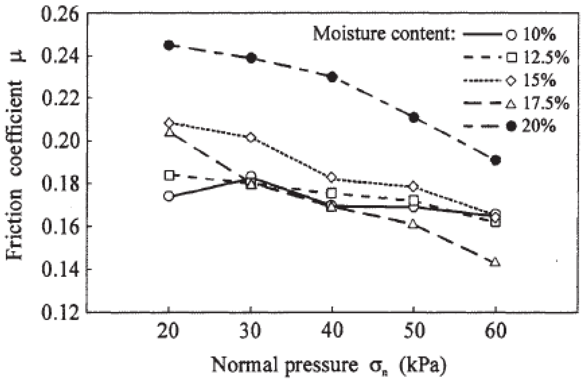
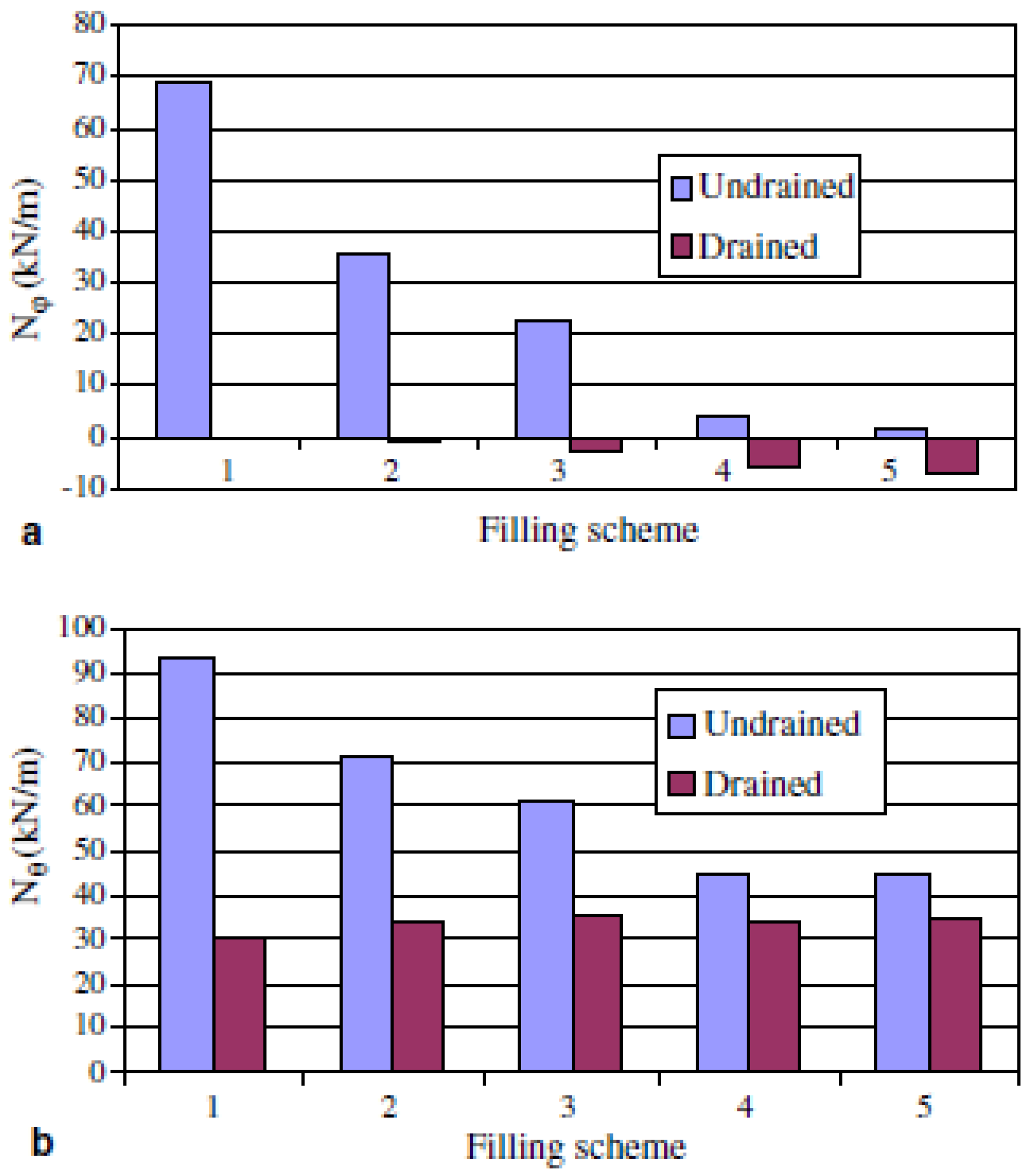
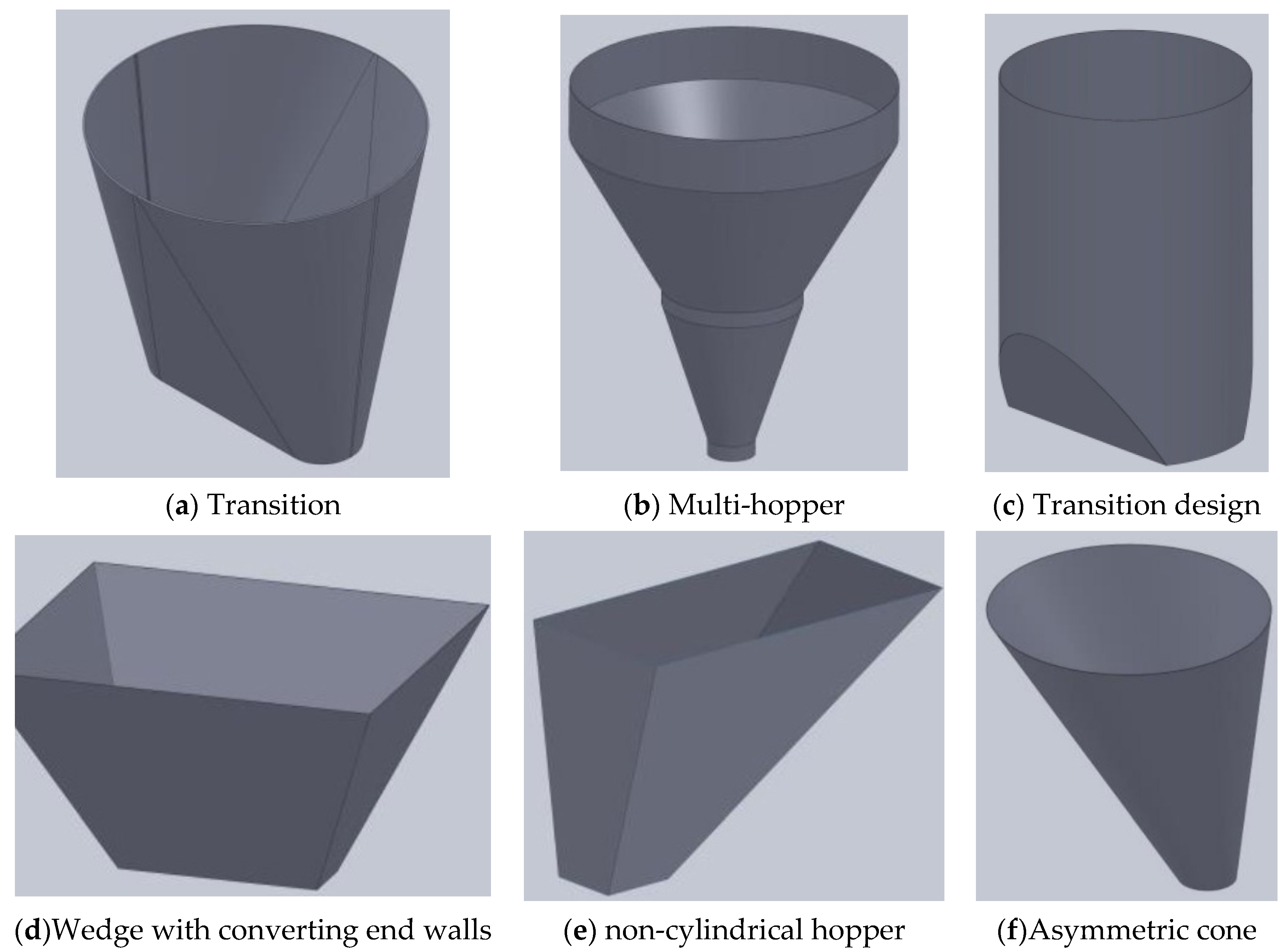
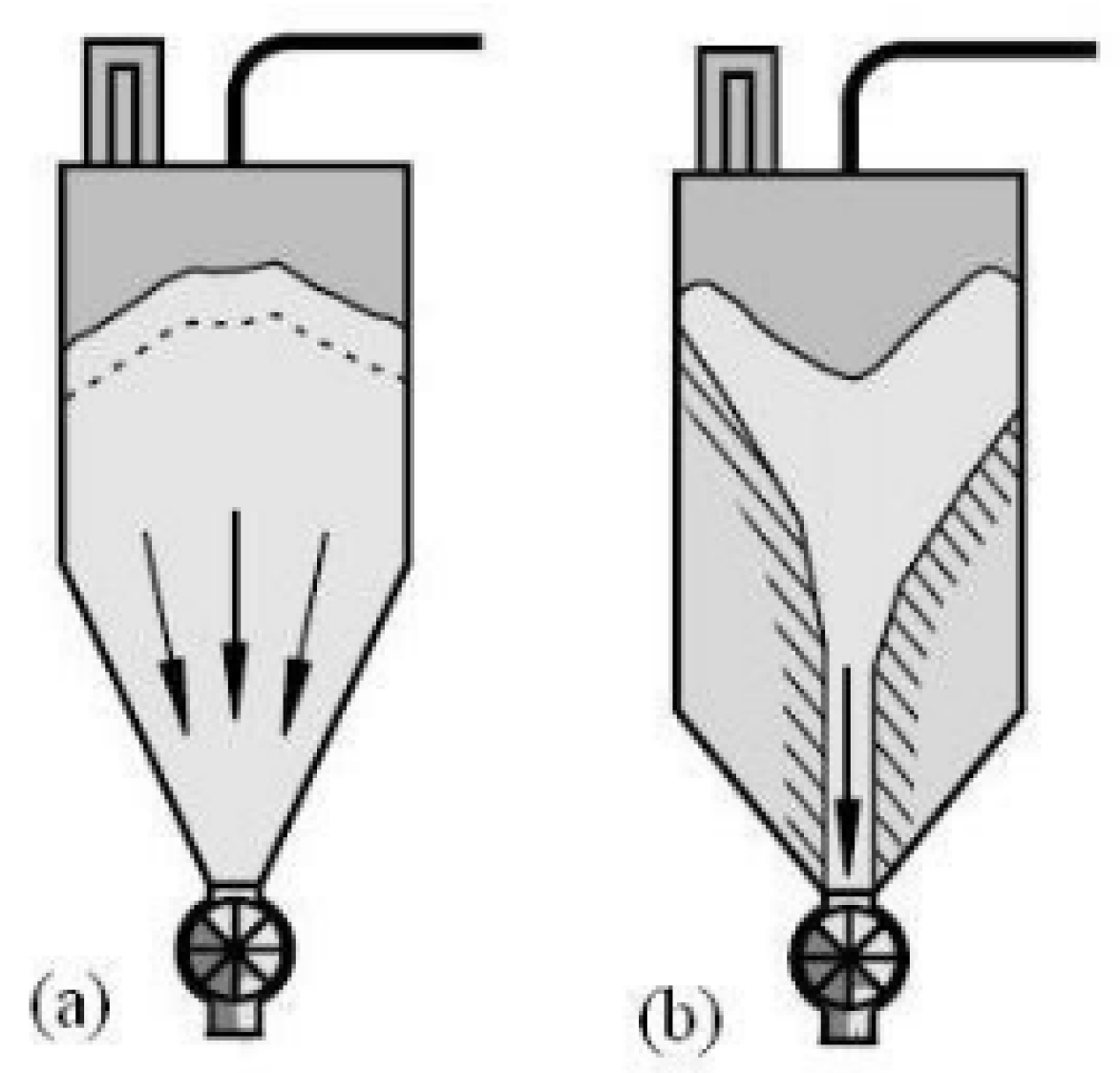
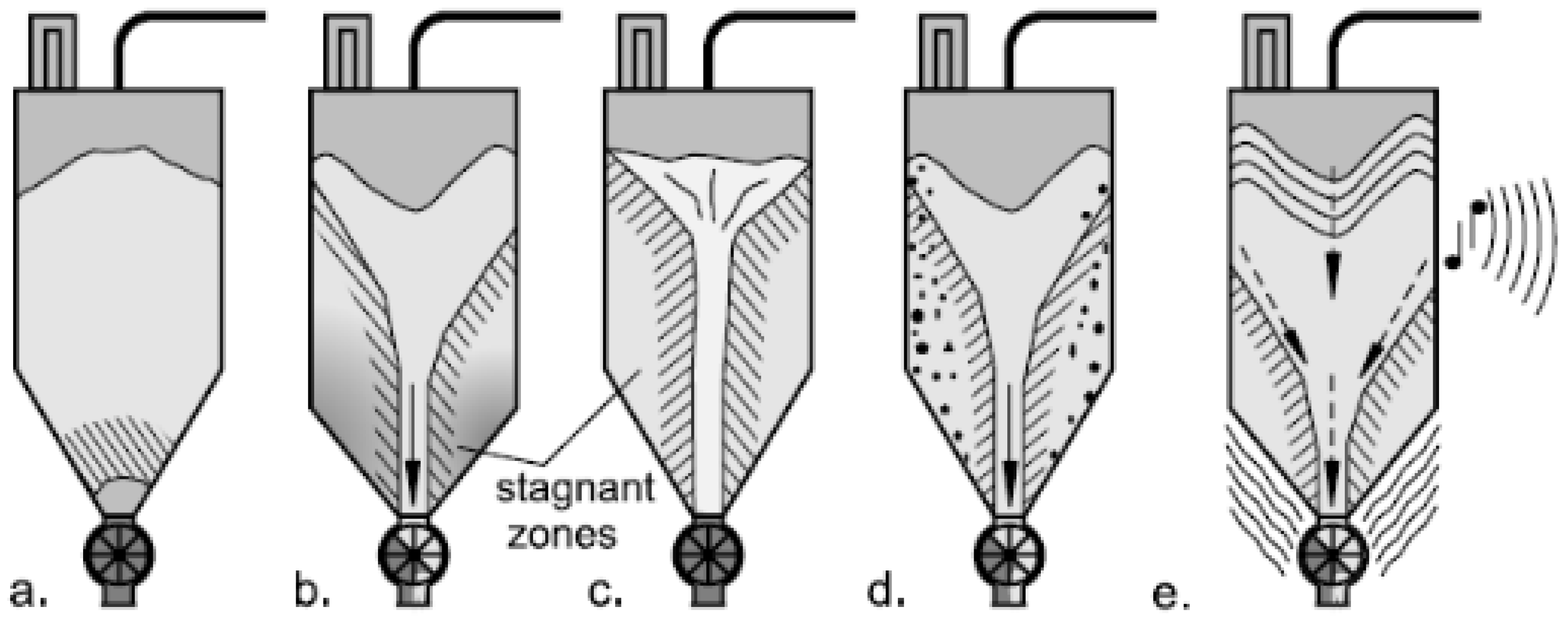
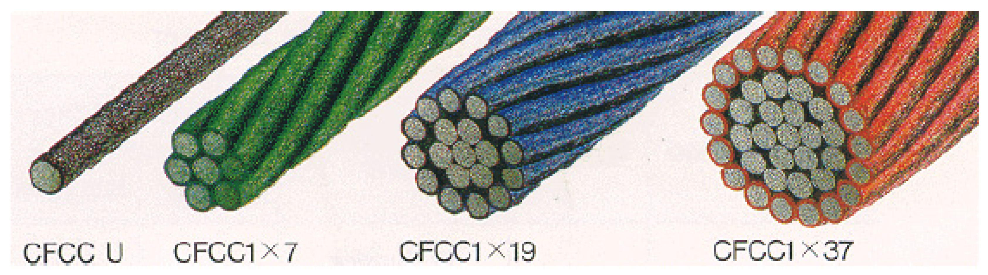
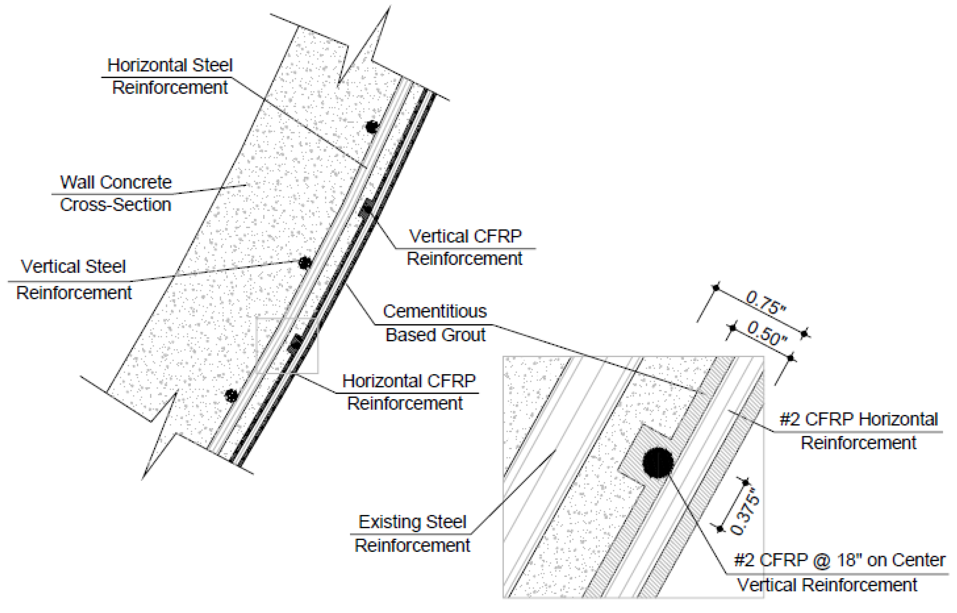
Table 1.
Coefficients for thermal expansion for selected materials used in concrete reinforcement [25].
Table 1.
Coefficients for thermal expansion for selected materials used in concrete reinforcement [25].
| Type of Concrete Reinforcement | Thermal Expansion Coefficient (1/°C) (Longitudinal) | Thermal Expansion Coefficient (1/°C) (Transverse) | Values in the Literature (1/°C) (Longitudinal) | Values in the Literature (1/°C) (Transverse) |
|---|---|---|---|---|
| Steel | 11.3 × 10⁻⁶ | 11.3 × 10⁻⁶ | 11.7 × 10⁻⁶ | 11.7 × 10⁻⁶ |
| GFRP | 4.43 × 10⁻⁶ | 22.5 × 10⁻⁶ | 6–10 × 10−6 | 21–23 × 10−6 |
| CFRP | 1.05 × 10⁻⁶ | 93 × 10−6 | (−9)–(0) × 10−6 | 74–104 × 10−6 |
| AFRP | −5.2 × 10⁻⁶ | 51 × 10−6 | (−6) × 10−6 | 60–80 × 10−6 |
| BFRP | 1.92 × 10⁻⁶ | 17.1 × 10⁻⁶ | 4 × 10⁻⁶ | 18–26 × 10−6 |
Table 2.
Strength grade of different concrete used for concrete silo construction [29].
Table 2.
Strength grade of different concrete used for concrete silo construction [29].
| Consistency Test (Slump Test) | ||||
| 0 | 3 | 10.33 a | 0.47 | 6.00 |
| 3.0 | 3 | 9.50 a | 0.41 | |
| 4.5 | 3 | 7.16 b | 0.24 | |
| 6.0 | 3 | 6.33 b | 0.47 | |
| fc medium—28 days (MPa) | ||||
| Axial Compression Test on Cylindrical Specimens | ||||
| 0 | 4 | 5.45 c | 0.12 | 6.39 |
| 3.0 | 4 | 14.86 a | 0.73 | |
| 4.5 | 4 | 12.94 b | 0.65 | |
| 6.0 | 4 | 2.69 d | 0.14 | |
| Tensile Test in Bending on Prismatic Specimens | ||||
| 0 | 4 | 5.78 b | 0.00 | 10.55 |
| 3.0 | 4 | 8.30 a | 1.11 | |
| 4.5 | 4 | 8.15 a | 0.42 | |
| 6.0 | 4 | 5.33 b | 0.00 | |
Table 3.
Composition of different concrete used for concrete silo construction [30].
Table 3.
Composition of different concrete used for concrete silo construction [30].
| Physical Properties | Chemical Properties | ||
|---|---|---|---|
| Specific Weight | 2.98 gr/cm3 | Ignition Loss | 1.20% |
| Specific Surface (Blaine) | 3135 cm2/gr | SiO2 | 19.80% |
| Volume Expansion | 3 mm | Al2O3 | 5.71% |
| Initial Set | 160 min. | Fe2O3 | 3.14% |
| Final Set | 235 min. | CaO | 63.23% |
| 2-day Compressive Strength | 25.0 MPa | MgO | 2.43% |
| 7-day Compressive Strength | 34.4 MPa | SO3 | 2.85% |
| 28-day Compressive Strength | 49.1 MPa | Cl | 0.006% |
Table 4.
Variations in grain quality parameters in termite mound clays, reinforced concrete, and galvanized steel silos [35].
Table 4.
Variations in grain quality parameters in termite mound clays, reinforced concrete, and galvanized steel silos [35].
| Type of Storage Silo | Storage Period (Months) | Moisture Content (%) | Maize Quality Parameters (%) | ||||
|---|---|---|---|---|---|---|---|
| Protein Content | Oil Content | Crude Fiber | Starch Content | Ash Content | |||
| 0 | 11.2(0.1) | 10.6(0.1) | 5.1(0.1) | 0.2(0.0) | 60.6(0.1) | 1.06(0.03) | |
| 2 | 11.8(0.1) | 10.3(0.1) | 4.8(0.2) | 0.2(0.1) | 60.5(0.5) | 1.01(0.03) | |
| Termite Mound clay | 4 | 11.7(0.2) | 9.9(0.1) | 4.7(0.4) | 0.2(0.0) | 60.1(0.6) | 0.91(0.05) |
| 6 | 13.4(0.1) | 9.5(0.4) | 4.5(0.1) | 0.3(0.1) | 59.3(0.2) | 0.94(0.04) | |
| 8 | 16.0(0.2) | 8.3(0.2) | 4.6(0.4) | 0.5(0.2) | 59.1(0.7) | 0.96(0.04) | |
| 0 | 11.2(0.1) | 10.6(0.1) | 5.1(0.1) | 0.2(0.0) | 60.6(0.1) | 1.06(0.03) | |
| 2 | 11.4(0.1) | 9.9(0.1) | 4.8(0.2) | 0.2(0.1) | 60.3(0.2) | 1.00(0.06) | |
| Reinforced concrete | 4 | 11.8(0.2) | 10.0(0.2) | 4.7(0.2) | 0.2(0.1) | 59.7(0.6) | 0.95(0.02) |
| 6 | 13.3(0.3) | 9.1(0.5) | 4.6(0.5) | 0.2(0.1) | 59.3(0.7) | 0.99(0.02) | |
| 8 | 15.1(0.3) | 10.0(0.3) | 4.7(0.5) | 0.4(0.1) | 58.2(0.7) | 0.99(0.04) | |
| 0 | 11.2(0.1) | 10.6(0.1) | 5.1(0.1) | 0.2(0.0) | 60.6(0.1) | 1.06(0.03) | |
| 2 | 11.3(0.2) | 10.2(0.2) | 5.0(0.2) | 0.3(0.1) | 59.8(0.4) | 1.02(0.04) | |
| Galvanized steel | 4 | 11.0(0.3) | 10.2(0.3) | 4.6(0.2) | 0.2(0.1) | 60.4(0.2) | 0.94(0.03) |
| 6 | 11.8(0.3) | 9.6(0.3) | 4.5(0.4) | 0.3(0.0) | 59.9(0.5) | 0.96(0.03) | |
| 8 | 12.7(0.4) | 9.9(0.4) | 4.7(0.2) | 0.3(0.1) | 59.0(0.9) | 0.97(0.07) | |
Table 5.
Relationship between the bulk grain coefficient of internal friction and the moisture content for oat, corn, and barley [49].
Table 5.
Relationship between the bulk grain coefficient of internal friction and the moisture content for oat, corn, and barley [49].
| Grain | Moisture | Angle of | Pressure Ratio | ||
|---|---|---|---|---|---|
| Content | Internal Friction | Measured | Calculated kf. | ||
| w.b. (%) | ϕ (0) | Ks | Eurocode 1 | Jaky | |
| 10 | 27.8 ± 0.4 | 0.45 ± 0.02 | 0.59 | 0.48 | |
| 12.5 | 28.5 ± 0.5 | 0.47 ± 0.03 | 0.56 | 0.47 | |
| Barley | 15 | 31.2 ± 0.3 | 0.43 ± 0.02 | 0.50 | 0.43 |
| 17.5 | 30.6 ± 1.0 | 0.45 ± 0.03 | 0.54 | 0.43 | |
| 20 | 33.2 ± 0.5 | 0.39 ± 0.03 | 0.51 | 0.40 | |
| 10 | 26.7 ± 0.6 | 0.48 ± 0.04 | 0.60 | 0.49 | |
| 12.5 | 31.7 ± 0.5 | 0.40 ± 0.03 | 0.52 | 0.42 | |
| Corm | 15 | 32.0 ± 1.4 | 0.36 ± 0.05 | 0.51 | 0.41 |
| 17.5 | 33.4 ± 0.8 | 0.34 ± 0.03 | 0.50 | 0.40 | |
| 20 | 33.6 ± 1.5 | 0.30 ± 0.05 | 0.51 | 0.39 | |
| 10 | 22.1 ± 1.1 | 0.49 ± 0.03 | 0.67 | 0.57 | |
| 12.5 | 22.4 ± 0.9 | 0.44 ± 0.04 | 0.68 | 0.56 | |
| Oat | 15 | 24.0 ± 0.5 | 0.45 ± 0.03 | 0.64 | 0.54 |
| 17.5 | 23.9 ± 1.0 | 0.40 ± 0.03 | 0.66 | 0.54 | |
| 20 | 26.4 ± 1.7 | 0.41 + 0.06 | 0.63 | 0.50 | |
| 10 | 25.7 ±0.3 | 0.44 ±0.02 | 0.62 | 0.51 | |
| 12.5 | 26.2 ± 0.4 | 0.38 ± 0.01 | 0.61 | 0.50 | |
| Wheat | 15 | 27.0± 0.5 | 0.34 ± 0.02 | 0.60 | 0.49 |
| 17.5 | 33.0 ± 1.0 | 0.31 ± 0.02 | 0.50 | 0.40 | |
| 20 | 35.5 ± 0.5 | 0.35 ± 0.0l | 0.46 | 0.37 | |
Table 6.
Relationship between ANN back-propagation methods and HN and errors (NCROWN) [63].
Table 6.
Relationship between ANN back-propagation methods and HN and errors (NCROWN) [63].
| Back- | Optimum | Training | Test | Training | R2 | ||
|---|---|---|---|---|---|---|---|
| Propagation | Number | ANN | Error | Error | Iteration | Time | |
| Methods | of HN | Structure | (%) | (%) | Number | (Second) | (%) |
| BFG | 6 | 3:6:1 | 0.38 | 1.80 | 2813 | 49.17 | 98.37 |
| CGB | 6 | 3:6:1 | 3.21 | 3.20 | 1148 | 7.97 | 98.45 |
| CGF | 6 | 3:6:1 | 0.41 | 3.12 | 839 | 5.91 | 98.38 |
| CGP | 6 | 3:6:1 | 0.44 | 3.19 | 658 | 4.61 | 98.19 |
| GDA | 4 | 3:4:1 | 3.59 | 5.27 | 5000 | 11.96 | 96.55 |
| GDM | 6 | 3:6:1 | 6.55 | 8.27 | 5000 | 12.05 | 92.68 |
| GDX | 4 | 3:4:1 | 2.34 | 5.76 | 5000 | 11.61 | 95.78 |
| LM | 4 | 3:4:1 | 0.27 | 1.28 | 3900 | 19.08 | 99.65 |
| OSS | 4 | 3:4:1 | 0.63 | 1.11 | 5000 | 43.02 | 99.87 |
| RP | 4 | 3:4:1 | 2.69 | 3.61 | 5000 | 13.22 | 98.22 |
| SCG | 4 | 3:4:1 | 0.25 | 0.58 | 5000 | 23.87 | 99.94 |
Table 7.
Relationship between lateral pressure, flow, and friction, and type of bulk material [23].
Table 7.
Relationship between lateral pressure, flow, and friction, and type of bulk material [23].
| Type of | Unit Weight | Angle | Effective Angle | Lateral | Max. Flow | |||
|---|---|---|---|---|---|---|---|---|
| Bulk Solid | of | of Internal | Pressure | Pressure | ||||
| γ | Repose | Friction | Ratio | Multiplier | ||||
| φr | φi | K or λ | Co | |||||
| γl | γu | φr | φil | φiu | Kl, λl | Ku, λu | ||
| Lower | Upper | Lower | Upper | Lower | Upper | |||
| kN/m3 | kN/m3 | Degrees | Degrees | Degrees | ||||
| Alumina | 10.0 | 12.0 | 27 | 25 | 40 | 0.42 | 0.53 | 1.40 |
| Barley | 7.0 | 8.5 | 20 | 26 | 33 | 0.50 | 0.63 | 1.35 |
| Cement | 13.0 | 16.0 | 28 | 40 | 50 | 0.45 | 0.58 | 1.40 |
| Cement clinker | 15.0 | 18.0 | 33 | 42 | 52 | 0.41 | 0.52 | 1.40 |
| Flour (wheat) | 6.5 | 7.0 | 40 | 23 | 30 | 0.36 | 0.46 | 1.45 |
| Fly ash | 8.0 | 14.0 | 22 | 30 | 35 | 0.41 | 0.52 | 1.45 |
| Iron ore pellets | 19.0 | 22.0 | 35 | 35 | 45 | 0.35 | 0.45 | 1.40 |
| Lime, hydrated | 6.0 | 8.0 | 40 | 35 | 45 | 0.35 | 0.45 | 1.40 |
| Limestone powder | 11.0 | 13.0 | 30 | 40 | 60 | 0.35 | 0.45 | 1.45 |
| Maize | 7.0 | 8.5 | 30 | 28 | 33 | 0.45 | 0.58 | 1.40 |
| Phosphate rock | 16.0 | 19.0 | 27 | 35 | 55 | 0.35 | 0.45 | 1.40 |
| Sand: coarse dry | 14.0 | 17.0 | 30 | 30 | 40 | 0.41 | 0.52 | 1.40 |
| Sand: quartz | 15.0 | 17.0 | 30 | 35 | 40 | 0.35 | 0.45 | 1.40 |
| Slag: granular, dry | 10.5 | 12.0 | 40 | 35 | 38 | 0.36 | 0.47 | 1.40 |
| Soya beans | 7.0 | 8.0 | 23 | 25 | 32 | 0.47 | 0.60 | 1.30 |
| Sugar | 8.0 | 9.5 | 29 | 33 | 38 | 0.45 | 0.58 | 1.40 |
| Wheat | 7.5 | 9.0 | 20 | 26 | 32 | 0.50 | 0.63 | 1.30 |
Table 8.
Rehabilitation of deteriorated concrete.
| Type of Damage on RC | Rehabilitation Method | Ref |
|---|---|---|
| Corrosion of RC | Reinforcement of concrete with alternative materials and corrosion inhibitors such as tolytriazole or sodium silicate | [76] |
| Exposure of steel reinforcement though abrasion | Surface furnishing, liners and sacrificial plates | [47] |
| Obstructions in the mass flow of the bulk solids | Addition of inserts and modification of design codes | [48] |
© 2020 by the author. Licensee MDPI, Basel, Switzerland. This article is an open access article distributed under the terms and conditions of the Creative Commons Attribution (CC BY) license (http://creativecommons.org/licenses/by/4.0/).
Share and Cite
MDPI and ACS Style
Maraveas, C. Concrete Silos: Failures, Design Issues and Repair/Strengthening Methods. Appl. Sci. 2020, 10, 3938. https://doi.org/10.3390/app10113938
AMA Style
Maraveas C. Concrete Silos: Failures, Design Issues and Repair/Strengthening Methods. Applied Sciences. 2020; 10(11):3938. https://doi.org/10.3390/app10113938
Chicago/Turabian StyleMaraveas, Chrysanthos. 2020. "Concrete Silos: Failures, Design Issues and Repair/Strengthening Methods" Applied Sciences 10, no. 11: 3938. https://doi.org/10.3390/app10113938
Note that from the first issue of 2016, this journal uses article numbers instead of page numbers. See further details here.