

Abstract
In this paper, we show that introductory physics students may initially conceptualise Cartesian coordinate systems as being fixed in a standard orientation. Giving consideration to the role that experiences of variation play in learning, we also present an example of how this learning challenge can be effectively addressed. Using a fine-grained analytical description, we show how students can quickly come to appreciate coordinate system movability. This was done by engaging students in a conceptual learning task that involved them working with a movable magnetometer with a printed-on set of coordinate axes to determine the direction of a constant field (Earth's magnetic field).
Export citation and abstract BibTeX RIS

Original content from this work may be used under the terms of the Creative Commons Attribution 4.0 licence. Any further distribution of this work must maintain attribution to the author(s) and the title of the work, journal citation and DOI.
1. Introduction
Learning how to appropriately select and use coordinate systems is central to physics modelling and problem solving. For example, a search of Institute of Physics (IOP) journals yields over a hundred thousand papers with the phrase 'coordinate systems' in the title. Yet, in undergraduate physics, coordinate systems are known to present a number of learning challenges for students—see, for example, Sayre and Wittmann (2008), and Vega et al (2017).
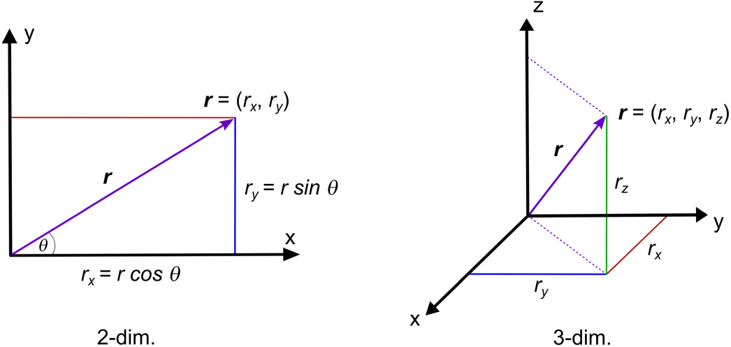
Although the setting up of a coordinate system is essentially an arbitrary process, in textbooks Cartesian coordinate systems are typically presented to students in one particular orientation—x increasing to the right, with y usually pointing 'up the page' (or z for 3D systems)—see figure 1, and the discussion in the next section. Such standardised presentation may initially lead to students conceptualising that coordinate systems are always fixed in this particular orientation (Volkwyn et al (2018)). However, unlocking the power of coordinate systems for physics problem solving involves appreciating their movability. Coordinate systems are not fixed but can be set up in any orientation we desire. Physicists typically use this property of coordinate systems and assign them in such a way so as to reduce complexity and thereby facilitate the solving of the physics problem at hand. In this paper we suggest that one of the reasons for initial student difficulties with using Cartesian coordinate systems to solve physics problems may, in part, stem from a failure to fully appreciate a coordinate system's movability.

Figure 1. Standard depictions of Cartesian axes in physics and mathematics textbooks.
Download figure:
Standard image High-resolution imageWe demonstrate how students engage with a hands-on, exploratory laboratory activity that allows them to directly experience the movability of coordinate systems without the need for tasks that involve numerical calculation. Central to our approach is the role that experiences of variation play in learning4. That is, students have the best possibility of noticing educationally important aspects when they are experienced as changing against an unvarying background (for physics examples, see Fredlund et al (2015), and Linder and Fraser (2006)). Thus, in this case, we sought to generate a learning task where the orientation of the coordinate system needed to be manipulated against an unchanging signal. Using this simple experimental design, we show how a pair of students rapidly move from what appears to be a belief that coordinate systems are fixed in a standard orientation to them experiencing themselves as holding a movable coordinate system in their hands. However, for the purposes of this paper, we do not describe or illustrate using variation theory as an analytical tool (for such an illustrative example, see Ingerman et al (2009)).
2. Challenges for students when learning about Cartesian coordinate systems
2.1. Up is more, right is more
Before ever learning about Cartesian coordinate systems in mathematics or physics at school, students have had the experience of change in a broad range of quantities as either increasing from left to right, or bottom to top. We argue that these operate as p-prims5 for students, 'up is more', and 'left to right is more', in western culture6. The effect of these p-prims in producing 'alternative conceptions' and transient learning challenges (Fredlund et al (2015)) should not be underestimated, even for university students.
2.2. Physics textbook depictions of Cartesian coordinate systems
As stated in the introduction to this paper, physics textbooks tend to depict Cartesian coordinate systems in standard ways. As an example of this practice, we present a quotation from an American Association of Physics Teachers (AAPT) reference textbook for college students applying mathematics as a tool for science work (the diagrams used to explicate the text are very similar to those in figure 1):
With Cartesian coordinates in two dimensions, you locate points by constructing a horizontal reference direction, called the x axis, and a vertical reference direction, called the y axis [...]. The x distance, the abscissa, is always first, then the y distance, the ordinate. In the case of three dimensions, the coordinates are listed (x, y, z) and the graph looks like the corner of a room where two walls and a floor meet' (Swartz (1993), p 122).
Whereas for 2D frames the +x direction is coupled to horizontality and 'to the right',for 3D systems the x–y plane is visualised as a horizontal floor of a room with the z-axis representing the 'up' direction. In the absence of a discussion of the arbitrariness of choices being made, these standardised depictions can reinforce students' perception of reference frames being fixed. This is problematic from the viewpoint of students needing to learn the disciplinary ways of using coordinate systems, where movability is an essential aspect of this use.
The two factors stated above are most likely to cause difficulties if learning activities do not directly address the movability aspect. Some curricular materials do this purposefully, for example see Allie and Buffler (1998) and Reese (2000). An explicit focus on teaching the movability of coordinate systems is key to helping students move towards a more disciplinary understanding and use of coordinate systems.
3. The study
Before we present our analysis of a learning activity designed to foster the appreciation of Cartesian coordinate system movability, we need to provide some context. We will first present the area of physics used for the learning task and explain why we are proposing it to be especially well-suited as a learning sequence dealing with the movability of Cartesian coordinate systems in physics problem solving. Then, we present the tool we used, the iOLab, which played a crucial role in providing needed experiences of variation for the learning task.
3.1. The physics context: Earth's magnetic field
For the purpose of this article, we have, as a variation design principle, chosen to study students working with a physically moveable Cartesian coordinate system to find the direction of the essentially invariant Earth's magnetic field in their classroom. At the same time, for the introductory level students involved in our study, it is not unreasonable to assume that the situated direction of the Earth's magnetic field would be hazy, if not unknown.
We provided the students with a wireless device with a 3D magnetometer (see the next sub-section on the iOLab) and asked them to determine the direction of the Earth's magnetic field in their classroom and then use a cut-out paper arrow to present this direction visually. The students could move and turn the magnetometer in any way they preferred. However, some orientations naturally made the task easier than others. The problem is most easily solved by systematically rotating the device so that first one, and then two components of the magnetic field become zero. The third, non-zero component then gives the magnitude and direction of the field.
Note that, for the majority of physics problems, physicists assign a coordinate system in some way in order to best follow some change in physical properties. The power of the task we gave to students is that these roles were reversed. The magnetic field that students wished to find the direction of was constant and the same for all the students in the classroom, whilst it was the orientation and movement of the Cartesian coordinate system that was changed. This provided the experience of variation set against a background of invariance (the direction of the magnetic field throughout the classroom). In other words, an activity that could facilitate the kind of educationally important discernment that becomes possible from the purposeful experiencing of differences against a background of sameness—see Marton (2015) for an overview of the extensive research done in this area.
3.2. The iOLab—a tool for teaching physics
The iOLab—'an interactive Online Laboratory system'—is a physics laboratory system designed to be used in physics teaching and learning (see figure 2). Using its array of on-board sensors (3D magnetometer, 3D gyroscope, 3D accelerometer, optical wheel sensor, force probe, microphone, light intensity sensor, atmospheric pressure sensor, temperature sensor, connections to do electric circuit experiments) a host of physical phenomena can be investigated—see (Selen 2013) for a representative set of examples of possible activities and experiments. This educational tool has recently attracted the attention of developers of physics courses, most notably in active learning laboratory courses (Bodegom et al (2019); Holmes and Wieman (2018); Nair and Sawtelle (2018); Sokoloff et al (2018)).

Figure 2. The iOLab system. The sensor-box connects wirelessly via a transmitter-receiver (USB dongle) to a computer. Its mass is ∼200 g with dimensions 13 × 7.5 × 3.0 cm. The required sensor is selected from a drop-down menu to the left of the interface screen. Real-time data is then displayed in graphs to the right.
Download figure:
Standard image High-resolution imageThe 3D-magnetometer sensor measures the magnetic field in three mutually perpendicular directions which are independently plotted on a graph in real-time. Note also the printed setof axes on the iOLab sensor-box; henceforth simply referred to as the sensor-box. This turned out to be one of the more important features of the iOLab system, for our task and intended learning goals. It allows students to connect the displayed graphs (each component in its own colour) to physical directions in space via visual cues. Furthermore, the sensor-box, with its small dimensions and weight (see the caption of figure 2), can be hand-held and easily manipulated. Students can leverage their proprioception (the sense of how their body is positioned in space) to 'feel' the orientation of the sensor-box as they move it, while they pay attention to changes on the computer screen. In this way, they can attend to the graphs on the screen and the spatial orientation of the sensor-box simultaneously, using separate modes of perception.
4. Methods
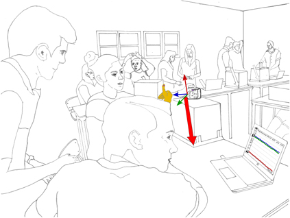
Our purpose in this paper is to make visible the ways in which students can engage with the iOLab with the given task and relate them to the learning goal of developing their appreciation of the movability of coordinate systems. We have previously used this same dataset to discuss the role of multimodality and measurement devices in physics education (Volkwyn et al (2019); Volkwyn et al (2018)). In this earlier work we focussed on how students typically used a range of communicative strategies to make sense of the measurements displayed on the screen. In order for us to better understand what the students are doing at any particular juncture, we need to attend not only to what they are saying, but also to their hand gestures, how they move the sensor-box, etc. To capture these diverse modalities of student interaction, we video-recorded multiple pairs of students (six) with a camera and free-standing microphones. In order to analyse the function of all the modalities of interaction, we first created a multimodal transcription (Baldry and Thibault (2006); Bezemer and Mavers (2011)). Here, we paid particular attention to the coordination of the sensor-box's orientation, the three-component graphical readout, and the students' and facilitators' use of speech, gesture and gaze. We will now present excerpts from our transcripts for one illustrative pair of students. Line sketches of actual video snapshots are presented together with the transcript excerpts and serve a double role. First, they make possible anonymization of students and second, they allow us to focus the reader's attention to what we see as the relevant aspects of each scene through the use of colour (see figure 3).
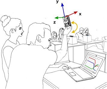
Figure 3. Our student pair working with the iOLab system. Notice in the background the original placement of the sensor-boxes on top of large boxes to isolate the magnetometer sensors from any electric or ferro-magnetic sources in the room. Reproduced from Volkwyn et al (2019). CC BY 4.0.
Download figure:
Standard image High-resolution image5. Findings
Below, we present our analysis of the engagement of one pair of students when using the iOLab. Here we ask the following research question:
In the context of the presented conceptual learning activity, how, without engaging in numerical calculations, can students come to experience and appreciate the movability of coordinate systems?
The excerpts we have selected relate to the learning path the students followed to discover the movability of coordinate systems. The excerpts are presented in chronological order and exemplify important phases of the learning sequence. For simplicity of presentation, speech is italicised text, transcriber comments are within normal brackets, and all other multimodal activities occurring in concert with speech appear in square brackets below the speech. Three full stops in a row [...] denote significant pauses in speech or interruptions by speech of other participants. The two students were given the symbols S1 and S2, and the participating teaching staff, which we refer to as facilitators, F1 and F2.
5.1. Excerpt 1—movement leads to change
Shortly after the students began the activity, they noticed that moving the sensor-box results in changes in the displayed plots (figure 3).
S1: holy crap, holy crap ... ummh, yeah, moving it changes it of course, so I guess we could figure out by the amount....
The students came up with explanations of the graph axes based on prior experiences,and tried to connect the information provided on the graph to the task. However, the students were not yet able to make productive interpretations for the given task. Nonetheless, a short engagement with a facilitator towards the end of this phase resulted in the students finally linking the printed axes on the sensor-box to the three colour lines which plotted the Cartesian components of the magnetic field. The meaning of the graphical output still eluded them, however.
The next phase was typified by the students starting to make productive interpretations, which they did by leveraging the connections they had made and testing their ideas directly with the iOLab system—positions referenced to the printed axes compared to graph lines. In particular, they now explored the meanings of zero, positive and negative. To exemplify this phase, we present the following examples.
5.2. Excerpt 2—the meaning of zero
One of the first meanings the student pair tried to work out was why different component values became 'close to zero' with the sensor-box placed in certain orientations. The transcript extract below represents a part of the interaction which took place between the students immediately before being joined by a facilitator (F1) and placing the sensor-box in the position shown in figure 4:
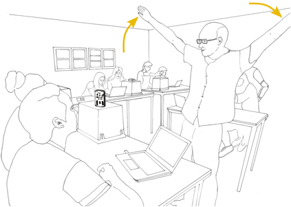
Figure 4. A facilitator recruits his own body by stretching out his arms in a right angle signifying a set of coordinate axes. He tilts his arms to demonstrate a repositioning of the orthogonal coordinate axes. Reproduced from Volkwyn et al (2019). CC BY 4.0.
Download figure:
Standard image High-resolution imageS1: Umm, if x is zero it means there's no...
S2: So, so, it is all, it is all...
(S2 makes up and down motion with arm)
S1: There's no magnetic, ...there is no reading from the magnet sensor in the x-plane, which means, uhh...
F1 then came by and proposed a kinematics analogy. He extended his arms at right angles to each other to represent a set of coordinate system axes, and asked the students what the size of the y-component (his left arm) of velocity will be, if the movement is in the direction of the x-axis (his right arm). He then tilted his extended arms at a 45° angle (see figure 4), and repeated the question for the new reference frame, with the motion now along the new x-axis (his tilted right arm). The students replied without hesitation that it will be 'still zero', which indicates that they successfully recruited their knowledge of applying coordinate systems in kinematics. The facilitator also made the following comment at the end of this engagement with the student pair:
F1: So you could reposition your own system... in a way that fits you, suits you.
(F1 makes swivelling gesture with right hand in front of his body).
Immediately after F1 departed from the group, our student pair started to devise a strategy to find the direction of the magnetic field. Essentially they planned to make first one, and then two components zero. By spontaneously and eagerly reaching out for the sensor-box, while using words such as 'tilt', 'move', 'be zero', the students were now fully utilising the pedagogical design of the iOLab system to 'feel' their way to a solution.
5.3. Excerpt 3—extrapolating to a second component
Setting the sensor-box so that one component is zero is relatively simple; getting two components to show zero at the same time requires greater depth of awareness of what the readouts on the screen imply in relation to the positioning of the axes printed on the sensor-box and what that means for the magnetic field vector. It is at this juncture that the students started to truly reflect on the meaning of a negative component. At first they were confused:
S1: Isn't that z? I do not understand, that should be z!
(S1 moves the sensor-box towards him slightly, and looks at screen).
(While holding the sensor-box so that the x-component remains zero, S1 is now trying to make the z-component zero; the +z-axis in a line away from S1, y still up, x to his left).
S2: That should be z
S1: It is not moving! (referring to the green line on the screen).
S1 was clearly confused about why the z-component did not change by simply translating the sensor-box along a line implied by the printed-on axis, keeping the orientation fixed. This indicated to us that at this stage he was only coupling the numerical size and algebraic sign of the component value to his directional intuition (something should change by translating it). A silence ensued with S1 manipulating the sensor-box some more. The students then decided to try and make the y-component zero. Still holding the sensor-box with the x-value zero—and +y-axis pointing up—S2 moved it from the top of the plastic box upwards in a straight line. See figure 5 and note that the y-plot was negative and changed very little as she moved the sensor-box upwards.
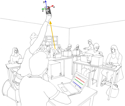
Figure 5. S2 gets off her chair and learns that up is not necessarily 'more positive'.
Download figure:
Standard image High-resolution imageEvidently, the students were trying to leverage their own intuition (or p-prims) that 'towards is closer to zero' for the z-component and 'up is more' for the y-component (see Volkwyn et al (2018)). This phase also vividly illustrates the significant challenges of working with 3D coordinate systems. Despite agreeing on a successful strategy of rotating the sensor-box to make one component zero, the students then struggled to successfully extrapolate this to a second component. With one component zero, keeping the orientation steady, they reverted to wanting to move the sensor-box upwards and downwards, forwards and backwards, or right and left. Now, once again, they appeared to consider the orientation of the axes to be fixed in the orientation shown in textbooks.
5.4. Excerpt 4—zeroing two components and fixing the arrow
A short while later, the students decided to call for assistance—F2 joined the pair. Thestudents were guided in a Socratic fashion, which helped them resolve some of their confusions, especially as it pertained to the interrelatedness of the component values. The students were also led to reflect on what the component values meant for the description of the magnetic field (its direction). With some facilitator guidance, the students figured out that by rotating the sensor-box about an already-zeroed axis ('tilted') they could make a second component zero.
However, even when the students rotated the sensor-box in a way so that two components were zero, they still expressed some confusion about how this is possible. At this point the facilitator asked the students to fix the paper arrow in the direction of the one printed-on axis that was currently reading a non-zero value.
F2: So if you...let us...fix this, let us...just...set this arrow; I will give you some tape
F2: So this is your hypothesis
(F2 points at red cut-out paper arrow now fixed to the side surface of the plastic box.)
S1: Yeah
[S1 lets go of the sensor-box ('measurement device') on top of the plastic box and leans back (as if trying to 'take-in' the full view/picture)]
F2: So, if you now take this measurement device, ...
S1: Yeah
F2: And try to see if this hypothesis, like, holds, ...
S1: Yeah, ...
F2: How would you point the measuring device if you want just the x-component (letter emphasized) to be non-zero, and all the others to be zero?
All the meanings the students had made up to this point—figuring out the connections between the physics-specific resources, devising a strategy and productively implementing it after working out how moving the sensor-box ('device') would affect the component values—were now represented by the single red arrow, pointing towards the floor at a steep angle (see figure 6). With the arrow in this fixed position, F2 now based his probing questions on the notion of a static magnetic field (represented by the arrow) and a movable coordinate system which is manipulated with respect to this field. The discussion about the meaning of a zero value for a given component could now take place with the arrow serving as a 'hub' for interaction (Fredlund et al (2012)).
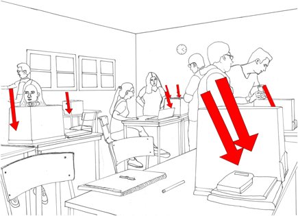
Figure 6. Cut-out arrows pasted by student pairs provided a powerful visual representation of the Earth's magnetic field in a laboratory classroom in Sweden. Reproduced from Volkwyn et al (2019). CC BY 4.0.
Download figure:
Standard image High-resolution imageF2: Why is it zero?
S2: How come?
F2: Good question. Where is y pointing now?
(F2 points at printed axes on the sensor-box and then pulls index finger in direction of +y.)
S2: Down... (smiles; signifying that she is aware that this is not the case).
F2: And how is it in relation to the field?
(F2 points at and touches arrow)
S2: Oh! It is, it is a ninety-degree angle then
[While holding the sensor-box in one hand, she first pulls her other hand towards her (in +y-direction), and then makes a right angle and draws her fingers over the arrow]
F2: Yes
S2: Ah-hah, that is so cool! Ahh, Wow!
(Broad smile directed at F2)
S1: Yeah, that makes sense
(S1 taps on table just before and after talking)
S2: Yeeesss!
What is striking here is S2's almost immediate and spontaneous response to F2's direct question about the spatial relationship between the y-axis and the cut-out arrow ('the field')—she suddenly realised that a particular component value is related to the angle(in this case 90°) between the respective reference axis (+y) and the 'static' physics quantity (the magnetic field). Importantly, her synchronized gestures—hand drawn along y-axis, then making a right angle immediately followed by tracing the arrow—and talk, '...it is a ninety-degree angle then', signified for us her taking on this meaning for herself. This was confirmed by both students' verbal appreciation and expression of joy at finally grasping the idea—an 'Ah-hah' moment.
In addition, by this time most of the groups were starting to fix their arrows. Figure 6 is a snapshot of the classroom. With this 'picture' of the magnetic field in the room, the students also learned something else about the Earth's magnetic field; that it is approximately invariant in the classroom, and that the direction has a steep dip into the ground.
5.5. Excerpt 5—students now test and cement their newly acquired understandings
F2 continued in a series of probing questions and follow-up discussions about how the manipulation of the sensor-box was related to the graphical readout in reference to the cut-out arrow. While holding the sensor-box in position near the arrow, with gaze checking the computer values, they were able to predict and explain the reasons for certain components being zero and the negativity (or not) of the non-zero component (figure 7).
Figure 7. S2 holds the sensor-box in position with her left hand, so that the x-axis printed on the sensor-box is anti-parallel to the arrow, with the yz-plane perpendicular to the arrow. Firstly, she curls her fingers while looking at the screen, and says, 'they are all zero'—referring to the zero y and z plots. Secondly, her thumb aligned opposite to the arrow accounts for the negative x plot—which she confirms with speech shortly after in discussion with the facilitator.
Download figure:
Standard image High-resolution image
F2: So now, if you want to align (emphasis) this vector to this vector, what should you do?
(F2 points in order at printed-on axes in direction of +z, then at red arrow)
S2: Ah-hah! This way ... ah, OK,
[S2 grabs the sensor-box (smiles broadly) and holds it with +z pointing directly opposite to the arrow]
F2: Yaahh...
[F2 looks at S1 (to check if he also gets it)]
S2: Yeah, ah-hah, ... it's a negative, ... because it is pointing this way and...
[S2 looks at screen and explains negative value with hand and finger first gesturing along direction of arrow (down at an angle), then draws index finger in opposite direction]
S1: Yeah
(S1 nods head up and down)
In figure 7, S2 used talk and gestures—curling her fingers in the plane perpendicular to the x-axis, and pointing her thumb in the opposite direction to the arrow—to show and explain respectively, why the y and z plots were both zero, and the x value was negative. F2 followed this up by asking the students to set the sensor-box in new positions—for example, 'What if you flipped it around?' which the students duly answered correctly. He then concluded his interaction with them by summarising what they had learned about coordinate systems.
6. Discussion
In what follows, we summarise how the research question has been addressed and answered.
We started this article by suggesting that introductory-level university students may initially view Cartesian coordinate systems as being fixed in standard orientations. This assertion issupported by the data analysis presented in the first part of this article. To address this transient learning challenge we wanted to provide students with an opportunity to notice the movability of coordinate systems. Following the variation approach described for physics-related contexts (as examples, see Fraser and Linder (2009); and Fredlund et al (2015)), in order for students to notice any disciplinary aspect, it needs to be varied whilst other disciplinary aspects remain constant (Marton (2015); Marton and Booth (1997)). To achieve this goal, we chose a relatively static, unknown quantity for the students to explore (the Earth's magnetic field) and provided them with a movable measurement tool (the iOLab sensor-box and system).
Following our experimental design, students needed to experience the variation of Cartesian coordinate system orientation against a background of invariant direction of magnetic field. This was achieved in three ways, first by having a tool that provided the students with a 'visible' coordinate system, second by having the students fix a paper arrow to denote their measured direction; and third, by the students seeing the same result arrived at by their peers—a spread of arrows fixed in the same orientation distributed throughout the classroom (see figure 6).
In most laboratory exercises, determining the magnitude and direction of an unknown quantity would signal the end of the laboratory task. However, in this case, our learning goals were focussed on students learning about the movability of coordinate systems. The arrow now served as a persistent, visual representation (Fredlund et al (2012); Volkwyn et al (2019)) of the constant background signal against which the movability of the coordinate system could be experienced. Up until this stage the students' attention had been focussed on finding the direction of the magnetic field by manipulating the sensor-box. Now, with this direction determined, students could turn their attention to the iOLab system (the sensor-box and the information on the computer screen) itself. In essence, students were encouraged to make sense of theprocess they had just gone through to fix the arrow in terms of the manipulation of a coordinate system. Here, the printed set of axes on the sensor-box became important. Students could now manipulate the sensor-box (and by extension, the coordinate system) into different orientations with respect to the arrow and check the outcomes on the screen. At this stage, the facilitator could probe the students' understandings of the meanings of the Cartesian components asking the students to predict the necessary orientations of the coordinate system that would achieve particular outcomes in the readouts of the three components on the screen. Furthermore, the students experienced movability without having to engage in numerical calculations. This aspect allowed the students to engage with the task in a pronounced conceptual way (see Hewitt for a discussion on learning physics conceptually).
The limited dataset we have presented in this paper does not allow a generalization of our results. However, what it does do is provide a rich description of how an educational experience can provide students with a new and meaningful learning experience through a fine grained analytical description. In other words, while we cannot claim that all (or even a majority) of physics students initially conceptualize coordinate systems as being fixed in standardized orientation, we have identified an illustrative example of students who do, and at the same time analytically show how this learning challenge may be effectively tackled.
7. Concluding remarks
In this paper we have demonstrated that some introductory physics students do think about Cartesian coordinate systems as though they are essentially 'locked' in one orientation. We give an example of how this learning challenge can be effectively addressed by getting students to engage with a movable measurement device (iOLab) in a constant field (the Earth's magnetic field). Based on this study, we propose that physics teachers explicitly address the movability of coordinate systems in the kind of way that we have exemplified in this paper.
Acknowledgments
We gratefully acknowledge funding support from the Swedish Research Council (project number VR 2016-04113). We greatly appreciate discussions with Saalih Allie, Anne Linder and Elias Euler who helped us develop some ideas for this article and the overall research project. A special word of thanks to Filip Heijkenskjöld for the planning and setting up of the experimental and recording equipment for the learning activity, as well as facilitating permission to conduct the study with the participating teaching staff and students at the learning institution (whom we also warmly thank).
Footnotes
- 4
- 5
DiSessa (1993) theorised that students learn physics (and other disciplines) by appealing to their sense of mechanism of the physical world. Everyday experiences of the world are loosely structured into heuristics he called phenomenological primitives (abbreviated as p-prims). One example used in this paper is 'up is more'. DiSessa argued that students draw on these heuristics when trying to make sense of physical phenomena.
- 6
These everyday experiences are reinforced by the design of scientific devices—for example, a thermometer has printed on its surface a temperature scale increasing in values from the bottom to the top- and 'sliders' on computer interfaces where up or to the right is always 'more'.