Article

Cooling Enhancement and Stress Reduction Optimization of Disk-Shaped Electronic Components Using Nanofluids

by
Reza Dadsetani
1,
Ghanbar Ali Sheikhzadeh
1,
Mohammad Reza Safaei
2,*,
Arturo S. Leon
2 and
Marjan Goodarzi
3
1
Heat & Fluids Department, University of Kashan, Kashan 87317-51167, Iran
2
Department of Civil and Environmental Engineering, Florida International University, Miami, FL 33174, USA
3
Sustainable Management of Natural Resources and Environment Research Group, Faculty of Environment and Labour Safety, Ton Duc Thang University, Ho Chi Minh City 700000, Vietnam
*
Author to whom correspondence should be addressed.
Symmetry 2020, 12(6), 931; https://doi.org/10.3390/sym12060931
Submission received: 18 March 2020 / Revised: 15 April 2020 / Accepted: 1 May 2020 / Published: 3 June 2020
(This article belongs to the Special Issue Future and Prospects in Non-Newtonian and Nanofluids)

Abstract

:
Mechanical strength and thermal properties may limit the usage of an electronic component in the high-tech industry. This paper investigated the influence of using CuO nanoparticles in a radial configuration microchannel of a disk from the mechanical and thermal points of view. In this regard, a disk under thermal and mechanical loading had been considered. The cooling setup consisted of a radial configuration microchannel with a constant fluid volume. Water was used as the base fluid and CuO particles were used as the coolant fluid. The results showed that the use of CuO nanoparticles would reduce the maximum disk temperature, the maximum thermal stress, and the maximum stress, as well as the maximum deformation on the body. The increasing number of channels would increase the maximum stress in the object as well. Another remarkable point was that increasing the nanoparticles did not necessarily lead to a more uniform heat distribution in the disk.

1. Introduction

One of the crucial parameters in technology advancement is the efficiency of electronic components. One of the main limitations affecting the performance of electronic components is transferring the heat from them. Wide ranges of studies have been carried out on this subject, and different approaches have been proposed [1,2,3,4,5,6,7,8,9,10,11,12,13,14]. One of these methods is using microchannels containing cooling fluids. This method was first introduced in 1981 by Tuckerman and Peace [15]. They showed that by using microchannels, heat transfer could be increased up to 40 times higher, and introduced microchannel-cooling as a high-efficiency small-sized method. After demonstrating the high efficiency of cooling with microchannels, the researchers studied the different applications, design aspects, and optimization of this method. The constructal theory is one of the optimization theories introduced by Adrian Bejan [16] that could be used to improve the heat sinks microchannel. This theory aims to enhance the shape and configuration of a microchannel. One of the introduced microchannels configurations by the constructal theory in a disk is known as the radial configuration. In this study, this kind of microchannel configuration in the disk was pursued. Another solution to improve the microchannel cooling efficiency is to enhance the physical properties of the microchannel fluid. Generally, conventional fluids have low thermal conductivity. To overcome this problem, S.U.S. Chol [17] achieved a higher thermal conductivity in working fluid by adding nanoparticles of metals in the working fluid. Dispersing the nanomaterial in the base fluid has made nanofluid with higher conduction, which can transfer more heat. In the recent three decades, the use of various nanoparticles and their effectiveness on heat transfer has been studied and analyzed by various researchers [12,18,19,20,21,22,23,24,25,26,27,28,29,30,31,32].
Another challenge in the design of electronic components in advanced technologies, such as electronic packages and structures of future air vehicles industries, is the weight and strength restrictions of the element [33]. One of the ways of increasing the strength of the electronic component is to add materials with a higher strength coefficient, but the downside of this method is the increase in the element weight. Therefore, the challenge is increasing the strength of the element without increasing its weight. In these technologies, because of the high rate of heat transfer, the thermal stresses play a crucial role in the component strength.
Gosselin et al. [34] optimized the combination of the heat transfer and strength of the materials analytically. The beam profile loaded has been optimized for bending by enhancing the lifetime in the existence of sudden heating. Besides, the cross-section of the beam and the position of the steel bars have been investigated. Cetkin et al. [33,35] examined the effect of vascular design on the mechanical and thermal stress in the radial and dendritic microchannel network. They found that the cooling capability of the vascular design reduced by decreasing the thermal stress.
So far, the use of nanofluids in the radial configuration has not been studied extensively. Also, the lack of a proper study to analyze the stresses of a cooled piece by nanofluid is felt. Therefore, in this research, an electronic element that was under thermal flux and mechanical loading was considered. In order to cool the disk, some microchannels were embedded inside it. In all examined cases, the volume of embedded channels was assumed constant. Water/CuO nanofluid was used at 4% and 2% volume fraction. The effect of using nanofluid on the maximum temperature, the von Mises stress, thermal stress, and total deformation had been investigated.

2. Model

To model electronic cooling equipment, such as processors, a disk with a radius of R, the diameter of D, and the height of H = 0.1 D were considered. The ratio of the cooling zone to the volume of the disk was assumed to be 5% in all cases [15,16,31,32]. The radial duct diameter varied with the duct numbers. The outer surface of the disk had been considered stationary, whereas the top and bottom surfaces were considered moving. The disk center was considered as the entrance of the cooling fluid. After uniform heat exchange with the bottom disk, it exited the system through the edge of the disk. Figure 1 shows the schematics of the studied cooling system. In the following microchannel network, the microchannel was extended to all cooling zone in volume (convection method).
Because of the frequent utilization of silicon as the most popular solid in the electronics industry and water as base fluid, the properties of these two materials were considered and listed in Table 1.

2.1. The Governing Equations

Heat is transferred through the solid and fluid regions by conduction and convection, respectively. The radiative heat transfer and gravity forces were neglected. In this study, the hydraulic diameter of the microchannel was chosen greater than 10 µm, so the fluid could be considered as a continuum. Therefore, Navier–Stokes and Fourier equations could be applied. Moreover, the energy and Navier–Stokes equations were coupled with the equation of solid heat transfer. The conductivity was considered to be uniform and isotropic. Due to the significant value of the conductivity coefficient, lasting time was smaller than a second to attain a steady-state temperature inside the microchannel. Nanofluid was assumed to be incompressible with Newtonian behavior and had a laminar flow. Nanoparticles were assumed to be spherical and had the same diameter. The base fluid and nanoparticles moved with the same velocity, and they were at the same thermal conditions. In other words, the nanofluid mixture was homogeneous. According to the mentioned assumptions, the mass conservation and momentum equations for the nanofluid were as follows:
u x + v y + w z = 0
u u x + v u y + w u z = 1 ρ n f p x + μ e f f ρ n f 2 u
u v x + v v y + w v z = 1 ρ n f p y + μ e f f ρ n f 2 v
u w x + v w y + w w z = 1 ρ n f p z + μ e f f ρ n f 2 w
Here, 2 = 2 x 2 + 2 y 2 + 2 z 2 .
The energy equations for fluid was
ρ n f C p , n f ( U . T ) = K n f 2 T
Effective viscosity and nanofluid density were defined as follows:
ρ n f = ξ ρ n p + ( 1 ξ ) ρ b f
μ e f f = μ b f / ( 1 ξ ) 2.5 .
The proposed formula by Chol et al. [17], which considers the diameters well as the Brownian motion of the nanoparticles, was used to compute the effective conductivity of the nanofluid:
k e f f k b f = 1 + 64.7 × ξ 0.7460 ( d b f d n p ) 0.3690 ( k n f k b f ) × ( μ ρ b f α b f ) 0.9955 ( ρ b f B c T 3 π μ 2 L B F ) 1.231
where “LBF” is the mean free path of the base fluid, and “Bc” the Boltzmann constant (1.3807 × 10⁻²³ J/K), and µ was calculated as
μ = A × 10 B T C ,   C = 140 ( K ) ,   B = 247 ( K ) ,   A = 2.414 × 10 5 ( P a . s )
The distribution of temperature into the solid zones was obtained by solving the energy equation:
K s 2 T s = 0 2 T s = 0
The thermal boundary conditions for the upside surface was:
K s T y = q
Sidewalls were adiabatic. In the solid–solid and solid–liquid interfaces, and due to the continuity of temperature and heat flux and the fluid in the joint, we had:
K s T s l n | Ω = K n f T f n | Ω   a n d   T s | Ω = T n f | Ω
where Ω is a perpendicular vector to the solid–solid and solid–liquid interfaces. Based on previous findings, solid disks assumed isotropic, with elastic deformations. According to this hypothesis, Hoke law and momentum equations could be expressed as [35]:
σ x x x + τ y x y + τ z x z = 0 σ y y y + τ x y x + τ z x z = 0 σ z z z + τ y z y + τ x z x = 0
[ σ x x σ y y σ z z τ y z τ z x τ x y ] = E ( 1 + γ ) ( 1 2 γ ) [ 1 γ γ γ 0 0 0 γ 1 γ γ 0 0 0 γ γ 1 γ 0 0 0 0 0 0 1 2 γ 2 0 0 0 0 0 0 1 2 γ 2 0 0 0 0 0 0 1 2 γ 2 ] [ ε x x ε x y ε x z φ y z φ x z φ x y ]
The effect of the thermal stress on the disk was considered by the relationship between temperature and solid equations, which could be written as follows:
[ ε x x ε y y ε z z ϕ y z ϕ z x ϕ x y ] = [ ε m , x x ε m , y y ε m , z z ϕ m , y z ϕ m , z x ϕ m , x y ] ( T T r e f ) [ α α α 0 0 0 ]
Displacement and strain relations could be represented as below:
ε m , x x = r x x ε m , y y = r y y ε m , z z = r z z φ m , x y = r x y + r y x φ m , y z = r z y + r y z φ m , z x = r z x + r x z
Total deformation could be calculated as:
D e = r x 2 + r y 2 + r z 2
D e * = D e 2 R
Dimensionless variables could be defined as follows:
T * = T T i n q R K s
P * = ( P i n P o u t ) R 2 μ α f
The value of P* demonstrates the difference in overall pressure between the inlet and outlet of the duct. P* values of order 107 and 108 had been used, which showed Reynolds numbers smaller than 2000 in each channel. Also, we assumed γ = 0.33 and E* = 2 × 10 6 . The thermal expansion coefficient was considered equal to 10−4.

2.2. Grid-Independence Study and Validation

In order to mesh the geometry, an irregular grid was used. The grids were refined near the cooling zone and the interface. The results were analyzed at various mesh numbers to examine maximum velocity, the peak temperature (Tmax, Table 2), and the maximum stress (Table 3) to obtain less than 1% variation. The traditional package of simulation ANSYS CFX and ANSYS STATIC STRUCTURAL software was used for this purpose. For the velocity-pressure coupling, a SIMPLE algorithm was used. Convergence had been acquired with the error magnitudes less than 10−5. The geometry and other conditions in the current study were considered similar to Cetkin et al. [35]. As could be seen in Figure 2, there was an excellent agreement for thermal stress, mechanical load, and a combination of both loads between present modeling and findings of Cetkin et al. [35].

3. Result and Discussion
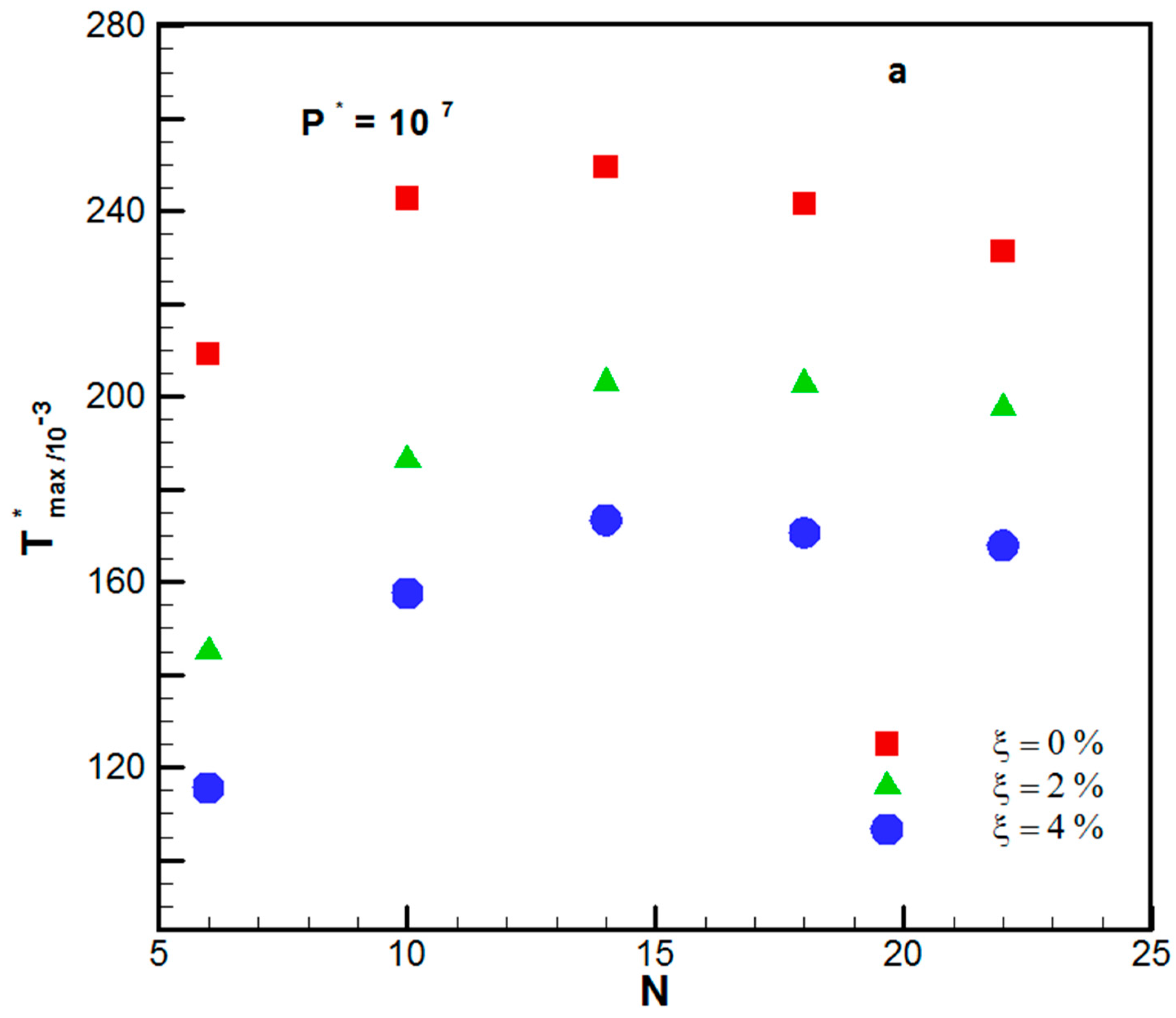
In this work, the vascular structures of a microchannel containing water and CuO- water nanofluid in a radial configuration were investigated. To achieve this goal, we examined the mechanical load, thermal load, and the cooling zone volume for all cases. Based on Equations (3) to (6), it was observed that the nanoparticle volume fraction had a significant effect on the overall thermal conductivity of the nanofluid, meaning that it was a much better heat conductor compared to the initial working fluid. Nevertheless, due to the increasing motions of the nanoparticles with temperature, which was a result of the Brownian effect, the thermal conductivity of the nanofluid depended mainly on the temperature. Furthermore, increasing the temperature caused the viscosity of the fluid to decrease, which facilitated the Brownian effect. The following sections discuss the effects of nanoparticle volume fraction on the thermal and mechanical behavior of the disk.

3.1. Thermal

The uniform maximum temperature and uniform temperature distribution are critical design parameters due to generating the best heat configuration. Based on the constructal theory, the ideal condition can be obtained when the temperature distribution becomes uniform over the component. On the other hand, the component’s best temperature is achieved when it reaches Tmax throughout the disk. The latter means that the best design is obtained when the average temperature is near Tmax.
Figure 3a,b represents the maximum dimensionless temperature variations by several ducts for different ξ = 0 % ,   2 % ,   and   4 % . Figure 3a,b indicates how the peak temperature changed, relative to the volume fraction of nanoparticles and the number of cooling channels, at P*max = 107 and P*max = 108, respectively. For P*max = 108, the peak temperature boosted as N increased when the volume fraction was 0%, 2%, and 4%. However, for P*max = 107, the peak temperature was obtained at N = 14. In both studied P*max, the peak temperature decreased as the volume fraction of nanoparticles increased. For the same N, the difference between maximum temperatures was larger for the range of ξ between 0% and 2% compared to that between 2% and 4%. For the studied cases, by increasing the volume fraction of nanoparticle from 0% to 2%, the peak temperature decreased from 14.5% to 30% (for P*max = 107) and 19.6% to 28.9% (for P*max = 108). Moreover, by nanoparticle volume fraction augmentation from 0% to 4%, the peak temperature decreased from 27.3% to 44% (for P*max = 107) and from 33.2% to 44.7% (for P*max = 108).
Table 4 shows the variation of the maximum temperature for various nanoparticles volume fractions and multiple numbers of microchannels. As shown in Table 4, Δ T max * is decreased when the number of ducts is increased.
A uniform temperature distribution, such as the maximum temperature of a segment, is important in the cooling of electronic parts. According to the constructal theory, the arrangement of microchannels is optimal once the whole segment would be at one unique temperature. The ideal condition is that the peak temperature and the segment temperature would be the same. Figure 4a,b indicates the uniformity of temperature based on the T ave T max . As observed in these figures, the best uniformity is obtained when using 10 ducts. According to Figure 4a, for P* = 107 and at duct numbers less than 10, the most uniformity of temperature was ascribed to the distilled water, in comparison with other concentrations of nanoparticles. The same results could be expressed for duct numbers less than ten and P* = 108. For duct numbers less than ten, the uniformity of temperature related to the concentration of 4% was less than 2% and 0%. However, for duct numbers greater than 10, the uniformity of concentration 4% was greater than the two other volume fractions.

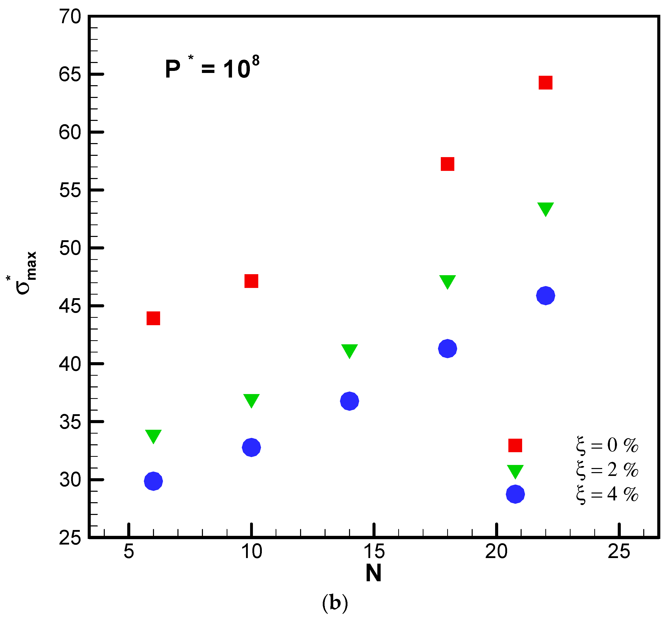
3.2. Mechanical Strength

Due to the development of electronic equipment and the growing tendency of engineers to decrease the weight and dimensions of electronic segments based on industry necessities, the investigation of the mechanical strength of the electronic components is crucial. In order to examine the mechanical strength of the electronic components, mechanical parameters, such as Von Mises stress, thermal stresses, and the total deformation, have been investigated. Thermal expansion can be defined as the tendency of matter to change the area, shape, and volume due to a change in temperature. The resulted strains are called the temperature strains, which are not able to generate stress without a constraint; thus, they can be introduced as free strains or strains without a force. The stress, which is created by the thermal load, significantly depends on the mechanical boundary conditions.
Figure 5a,b shows the change in peak thermal stress for various duct numbers. As observed in these figures, as a result of nanoparticle application, the peak thermal stress in the segment and the peak stress in the disks are decreased when the volume fraction of nanoparticles is increased. Whereas the peak stress in the disks increased with the duct numbers. It is noted that the slope of the stress-duct is reduced by enhancing the initial pressure and the volume fraction of nanoparticles, and eventually, the peak stress decreased. When P*max = 107 and P*max = 108, by increasing the volume fraction of nanoparticle from 0% to 2%, the peak thermal stress varied from 13.6% to 29% and 27.6% to 42.9%, respectively. Moreover, by increasing the volume fraction of nanoparticle from 0% to 4%, the peak thermal stress changed from 34.3% to 51% and 38% to 54%, respectively.
Figure 6a,b depicts the peak stress originated from thermal and mechanical loading (1 × 10⁵ Pa) for various duct numbers. Figure 6a,b shows that the use of nanofluid reduced the peak stress in the segment, and that the peak stress in the disks is decreased when the nanofluid volume fraction is increased. Besides, the greater the N, the greater the peak stress. Increasing the initial pressure diminished the peak stress. The thermal loading caused equal stress at the three orients of the coordinate system. However, the mechanical loading when considering the Poisson coefficient caused stress in opposite directions. Thus, the curve showed a non-linear behavior. When P*max = 107 and P*max = 108, by increasing the volume fraction of nanoparticle from 0% to 2%, the peak stress changed from 9.3% to 27% and 9% to 12.9%, respectively. Moreover, by raising the volume fraction of nanoparticle from 0% to 4%, the peak stress varied from 19% to 39% and 17% to 21%, respectively.
Deformation is described as the change in the metric characteristics of a continuous body, which means that a curve drawn at the initial body placement can change its length when it is displaced to a curve at the total placement [36]. Figure 7 shows the dimensionless peak total deformation of the disk under the thermal load for different numbers of the duct.
The peak deformation, which was originated from thermal loading, decreased by the increment of the nanoparticle volume fraction. At a volume fraction of 2% and 4%, an average reduction of 28.3% and 35.4% was observed, respectively. Also, among the different microchannels numbers, a ten microchannel duct had the minimum peak deformation. For a number of ducts above 10, the thermal peak deformation increased with the number of microchannels.
By increasing the number of microchannels, the peak temperature, and accordingly, the peak thermal stress increased. Moreover, the mechanical loading had been diminished in comparison with the thermal loading. Therefore, as observed in Figure 8, the peak deformation is increased with the number of microchannels, but the ascribed slope is decreased. This was due to the reduction in the effect of mechanical loading compared with thermal loading. By increasing the nanoparticle volume fraction, the peak deformation is decreased. For nanoparticle concentrations of 2% and 4%, between 4.3 to 17.3 and 5.7 to 23.2 percent change in the peak deformation could be observed.
In Figure 9, blue and red colors represent the maximum and minimum values, respectively. As observed in this figure, the maximum thermal strain and temperature of the disk had the same location. In addition, the minimum values are located halfway between the edge of the plate and the center. It is noted that the plate was considered a circle, concentric with the plate center.

4. Conclusions

In this paper, the influence of using dispersed CuO nanoparticles in H2O flowing through a network of radial microchannels from the mechanical and thermal points of view was investigated. In all studied cases, the fluid volume of the cooling zone was assumed to be constant in the solid region, and the effect of using nanofluid in concentrations of 2 and 4 percent was investigated. The results indicated that CuO nanoparticles reduced the average of the maximum disk temperature, the maximum thermal stress, and the maximum stress, as well as the most significant deformation in the studied configuration. Increasing the number of microchannels would increase the maximum stress in the object, as well. Another remarkable point was that increasing the nanoparticles did not necessarily lead to a more uniform heat distribution in the disk.

Author Contributions

All authors (R.D., G.A.S., M.R.S., A.S.L., and M.G.) have contributed equally. All authors have read and agreed to the published version of the manuscript.

Funding

This research received no external funding.

Conflicts of Interest

The authors declare no conflict of interest.

Nomenclature

Nomenclature
CpSpecific heat capacity (J kg−1 K−1)
DThe thickness of the microchannel (m)
DeDeformation (m)
HThe height of the disk (m)
LLength (m)
MMass flow rate (kg s−1)
NNumber of branching
PPressure (N m−2)
PrPrandtl number
qHeat flux (W m−2)
TTemperature (K)
u, v, wVelocity components (m s−1)
Greek symbols
AThermal expansion coefficient (K−1)
γPoisson’s ratio
σNormal stress (Pa)
µDynamic viscosity (kg m−1 s−1)
τShear stress (Pa)
ξThe volume fraction of nanoparticles
ρDensity (kg m−3)
φShear strain (mm mm−1)
Subscripts
aveAverage
bfBase Fluid
nfNano fluid
sSolid
refReference
Superscripts
(*)Dimensionless

References

  1. Bahiraei, M.; Salmi, H.K.; Safaei, M.R. Effect of employing a new biological nanofluid containing functionalized graphene nanoplatelets on thermal and hydraulic characteristics of a spiral heat exchanger. Energy Convers. Manag. 2019, 180, 72–82. [Google Scholar] [CrossRef]
  2. Farzaneh, M.; Salimpour, M.R.; Tavakoli, M.R. Design of bifurcating microchannels with/without loops for cooling of square-shaped electronic components. Appl. Therm. Eng. 2016, 108, 581–595. [Google Scholar] [CrossRef]
  3. Ghaedamini, H.; Salimpour, M.; Campo, A. Constructal design of reverting microchannels for convective cooling of a circular disc. Int. J. Therm. Sci. 2011, 50, 1051–1061. [Google Scholar] [CrossRef]
  4. Haghighi, S.S.; Goshayeshi, H.; Safaei, M.R. Natural convection heat transfer enhancement in new designs of plate-fin based heat sinks. Int. J. Heat Mass Transf. 2018, 125, 640–647. [Google Scholar] [CrossRef]
  5. Al-Rashed, A.A.A.; Hassen, W.; Kolsi, L.; Oztop, H.F.; Chamkha, A.J.; Abu-Hamdeh, N. Three-dimensional analysis of natural convection in nanofluid-filled parallelogrammic enclosure opened from top and heated with square heater. J. Cent. South Univ. 2019, 26, 1077–1088. [Google Scholar] [CrossRef]
  6. Dogonchi, A.; Chamkha, A.J.; Hashemi-Tilehnoee, M.; Seyyedi, S.; Ganji, D. Effects of homogeneous-heterogeneous reactions and thermal radiation on magneto-hydrodynamic Cu-water nanofluid flow over an expanding flat plate with non-uniform heat source. J. Cent. South Univ. 2019, 26, 1161–1171. [Google Scholar] [CrossRef]
  7. Dogonchi, A.S.; Chamkha, A.J.; Seyyedi, S.M.; Hashemi-Tilehnoee, M.; Ganji, D.D. Viscous Dissipation Impact on Free Convection Flow of Cu-water Nanofluid in a Circular Enclosure with Porosity Considering Internal Heat Source. J. Appl. Comput. Mech. 2019, 5, 717–726. [Google Scholar]
  8. Alkasassbeh, M.; Omar, Z.; Mebarek-Oudina, F.; Raza, J.; Chamkha, A. Heat transfer study of convective fin with temperature-dependent internal heat generation by hybrid block method. Heat Transf.—Asian Res. 2019, 48, 1225–1244. [Google Scholar] [CrossRef]
  9. Kumar, P.S.; Gireesha, B.; Mahanthesh, B.; Chamkha, A.J. Thermal analysis of nanofluid flow containing gyrotactic microorganisms in bioconvection and second-order slip with convective condition. J. Therm. Anal. Calorim. 2019, 136, 1947–1957. [Google Scholar] [CrossRef]
  10. Izadi, M.; Pour, S.H.; Yasuri, A.K.; Chamkha, A.J. Mixed convection of a nanofluid in a three-dimensional channel. J. Therm. Anal. Calorim. 2019, 136, 2461–2475. [Google Scholar] [CrossRef]
  11. Ghalambaz, M.; Tahmasebi, A.; Chamkha, A.; Wen, D. Conjugate local thermal non-equilibrium heat transfer in a cavity filled with a porous medium: Analysis of the element location. Int. J. Heat Mass Transf. 2019, 138, 941–960. [Google Scholar] [CrossRef]
  12. Bahiraei, M.; Jamshidmofid, M.; Goodarzi, M. Efficacy of a hybrid nanofluid in a new microchannel heat sink equipped with both secondary channels and ribs. J. Mol. Liq. 2019, 273, 88–98. [Google Scholar] [CrossRef]
  13. Dadsetani, R.; Sheikhzadeh, G.A.; Hajmohammadi, M.R.; Safaei, M.R. Introduce a novel configuration of microchannel andhigh-conductivity insertsfor cooling of disc-shaped electronic components. Int. J. Numer. Methods Heat Fluid Flow 2019. [Google Scholar] [CrossRef]
  14. Dadsetani, R.; Salimpour, M.R.; Tavakoli, M.R.; Goodarzi, M.; Bandarra Filho, E.P. Thermal and Mechanical Design of Reverting Microchannels for Cooling Disk-Shaped Electronic Parts Using Constructal Theory. Available online: https://doi.org/10.1108/HFF-06-2019-0453 (accessed on 20 March 2020).
  15. Tuckerman, D.B.; Pease, R.F.W. High-performance heat sinking for VLSI. IEEE Electron Device Lett. 1981, 2, 126–129. [Google Scholar] [CrossRef]
  16. Bejan, A. Street network theory of organization in nature. J. Adv. Transp. 1996, 30, 85–107. [Google Scholar] [CrossRef]
  17. Chol, S.; Estman, J. Enhancing thermal conductivity of fluids with nanoparticles. Asme-Publ.-Fed 1995, 231, 99–106. [Google Scholar]
  18. Dadsetani, R.; Sheikhzadeh, G.A.; Safaei, M.R.; Alnaqi, A.A.; Amiriyoon, A. Exergoeconomic optimization of liquefying cycle for noble gas argon. Heat Mass Transf. 2018, 55, 1995–2007. [Google Scholar] [CrossRef]
  19. Selimefendigil, F.; Chamkha, A.J. Magnetohydrodynamics mixed convection in a lid-driven cavity having a corrugated bottom wall and filled with a non-Newtonian power-law fluid under the influence of an inclined magnetic field. J. Therm. Sci. Eng. Appl. 2016, 8, 021023. [Google Scholar] [CrossRef]
  20. Selimefendigil, F.; Öztop, H.F. Effects of nanoparticle shape on slot-jet impingement cooling of a corrugated surface with nanofluids. J. Therm. Sci. Eng. Appl. 2017, 9, 021016. [Google Scholar] [CrossRef]
  21. Sheikhzadeh, G.; Dastmalchi, M.; Khorasanizadeh, H. Effects of walls temperature variation on double diffusive natural convection of Al2O3–water nanofluid in an enclosure. Heat Mass Transf. 2013, 49, 1689–1700. [Google Scholar] [CrossRef]
  22. Sheikhzadeh, G.; Nikfar, M. Aspect ratio effects of an adiabatic rectangular obstacle on natural convection and entropy generation of a nanofluid in an enclosure. J. Mech. Sci. Technol. 2013, 27, 3495–3504. [Google Scholar] [CrossRef]
  23. Teimouri, H.; Sheikhzadeh, G.A.; Afrand, M.; Fakhari, M.M. Mixed convection in a rotating eccentric annulus containing nanofluid using bi-orthogonal grid types: A finite volume simulation. J. Mol. Liq. 2017, 227, 114–126. [Google Scholar] [CrossRef]
  24. Bagherzadeh, S.A.; D’Orazio, A.; Karimipour, A.; Goodarzi, M.; Bach, Q.-V. A novel sensitivity analysis model of EANN for F-MWCNTs–Fe3O4/EG nanofluid thermal conductivity: Outputs predicted analytically instead of numerically to more accuracy and less costs. Phys. A Stat. Mech. Its Appl. 2019, 521, 406–415. [Google Scholar] [CrossRef]
  25. Afridi, M.I.; Tlili, I.; Goodarzi, M.; Osman, M.; Khan, N.A. Irreversibility Analysis of Hybrid Nanofluid Flow over a Thin Needle with Effects of Energy Dissipation. Symmetry 2019, 11, 663. [Google Scholar] [CrossRef] [Green Version]
  26. Nazari, M.A.; Ahmadi, M.H.; Sadeghzadeh, M.; Shafii, M.B.; Goodarzi, M. A review on application of nanofluid in various types of heat pipes. J. Cent. South Univ. 2019, 26, 1021–1041. [Google Scholar] [CrossRef]
  27. Jiang, Y.; Bahrami, M.; Bagherzadeh, S.A.; Abdollahi, A.; Sulgani, M.T.; Karimipour, A.; Goodarzi, M.; Bach, Q.-V. Propose a new approach of fuzzy lookup table method to predict Al2O3/deionized water nanofluid thermal conductivity based on achieved empirical data. Phys. A Stat. Mech. Its Appl. 2019, 527, 121177. [Google Scholar] [CrossRef]
  28. Nikkhah, Z.; Karimipour, A.; Safaei, M.R.; Forghani-Tehrani, P.; Goodarzi, M.; Dahari, M.; Wongwises, S. Forced convective heat transfer of water/functionalized multi-walled carbon nanotube nanofluids in a microchannel with oscillating heat flux and slip boundary condition. Int. Commun. Heat Mass Transf. 2015, 68, 69–77. [Google Scholar] [CrossRef]
  29. Safaei, M.R.; Gooarzi, M.; Akbari, O.A.; Shadloo, M.S.; Dahari, M. Performance evaluation of nanofluids in an inclined ribbed microchannel for electronic cooling applications. In Electronics Cooling; IntechOpen: Zagreb, Croatia, 2016. [Google Scholar]
  30. Akbari, O.A.; Toghraie, D.; Karimipour, A.; Safaei, M.R.; Goodarzi, M.; Alipour, H.; Dahari, M. Investigation of rib’s height effect on heat transfer and flow parameters of laminar water–Al2O3 nanofluid in a rib-microchannel. Appl. Math. Comput. 2016, 290, 135–153. [Google Scholar]
  31. Nojoomizadeh, M.; D’Orazio, A.; Karimipour, A.; Afrand, M.; Goodarzi, M. Investigation of permeability effect on slip velocity and temperature jump boundary conditions for FMWNT/Water nanofluid flow and heat transfer inside a microchannel filled by a porous media. Phys. E Low-Dimens. Syst. Nanostruct. 2018, 97, 226–238. [Google Scholar] [CrossRef]
  32. Menni, Y.; Azzi, A.; Chamkha, A. Enhancement of convective heat transfer in smooth air channels with wall-mounted obstacles in the flow path. J. Therm. Anal. Calorim. 2019, 135, 1951–1976. [Google Scholar] [CrossRef]
  33. Cetkin, E.; Lorente, S.; Bejan, A. Vascularization for cooling and mechanical strength. Int. J. Heat Mass Transf. 2011, 54, 2774–2781. [Google Scholar] [CrossRef]
  34. Gosselin, L.; Bejan, A. Constructal heat trees at micro and nanoscales. J. Appl. Phys. 2004, 96, 5852–5859. [Google Scholar] [CrossRef]
  35. Çetkin, E.; Lorente, S.; Bejan, A. Vascularization for cooling and reduced thermal stresses. Int. J. Heat Mass Transf. 2015, 80, 858–864. [Google Scholar] [CrossRef] [Green Version]
  36. Lubliner, J. Plasticity Theory; Courier Corporation: New York, NY, USA, 2008. [Google Scholar]
Figure 1. (a) Side view of the modeled disk. (b) Front view of modeled disk.
Symmetry 12 00931 g001
Figure 2. A comparison of the dimensionless maximum Von Mises stress, based on several microchannels, compared to Cetkin et al. [35] work.
Symmetry 12 00931 g002
Figure 3. (a) T*max versus N for the different volume fraction of nanoparticles under P* = 107. (b) T*max versus N for the different volume fraction of nanoparticles P* = 108.
Symmetry 12 00931 g003aSymmetry 12 00931 g003b
Figure 4. (a) Dimensionless average temperature versus the number of ducts at different ξ , under P* = 107; (b) Dimensionless average temperature versus the number of ducts at different under ξ , P* = 108.
Symmetry 12 00931 g004
Figure 5. (a) Peak thermal stress relative to the number of cooling channels for the varying volume fraction of CuO Nanoparticle under P*max = 107. (b) Peak thermal stress relative to the number of cooling channels for the varying volume fraction of CuO Nanoparticle P*max = 108.
Symmetry 12 00931 g005aSymmetry 12 00931 g005b
Figure 6. (a) Peak stress versus the number of cooling channels for the different volume fraction of CuO nanoparticle under P* = 107. (b) Peak stress versus the number of cooling channels for the different volume fraction of CuO nanoparticle under P* = 108.
Symmetry 12 00931 g006
Figure 7. Dimensionless peak total deformation versus the number of cooling channels for the varying volume fraction of CuO nanoparticles.
Symmetry 12 00931 g007
Figure 8. Dimensionless peak total deformation per N for various ξ .
Symmetry 12 00931 g008
Figure 9. The contours of (a) thermal strain, (b) stress, and (c) temperature under mechanical load.
Symmetry 12 00931 g009aSymmetry 12 00931 g009b
Table 1. Properties of considered solid and fluid.
PropertySiliconWater
Density, ρ (kg/m3)2330997
Thermal conductivity, k (W/m K)1250.6069
Specific heat capacity, Cp (J/kg K)7004187.7
Dynamic viscosity, μ (Pa.s)---0.00089
Table 2. Results in Tmax per number of elements.
Number of ElementsTmax (K)
879,314 435.9
2,169,346 429.8
3,256,892 425.6
5,142,765 424.3
Table 3. Results in σmax per number of elements.
Number of Elementsσmax (Mpa) Variation
879,314 3.4281
2,169,346 3.3452
3,256,892 3.1252
5,142,765 3.1118
Table 4. Percentage change in Δ T m a x * by changing the number of ducts for ξ = 2% and 4%.
Variation   Δ T max * Δ T max * T max * | 2 % T max * | 0 % | T max * | 0 % Δ T max * T max * | 4 % T max * | 0 % | T max * | 0 %
volume fraction of nanofluids ζ = 0 %   t o   2 % ζ = 0 %   t o   4 %
NP*max = 107P*max = 108P*max = 107P*max = 108
6 Δ T max * − 30.74% Δ T max * − 28.99% Δ T max * − 44.74% Δ T max * − 40.71%
8 Δ T max * − 23.27% Δ T max * − 28.02% Δ T max * − 35.05% Δ T max * − 39.61%
14 Δ T max * − 18.66% Δ T max * − 23.77% Δ T max * − 30.53% Δ T max * − 35.82%
18 Δ T max * − 16.14% Δ T max * − 21.52% Δ T max * − 29.38% Δ T max * − 34.99%
22 Δ T max * − 14.54% Δ T max * − 19.67% Δ T max * − 27.38% Δ T max * − 33.23%

