Applicability Study of Pulsed Laser Beam Welding on Ferritic–Martensitic ODS Eurofer Steel
by
 , ,
, ,
Jia Fu
1,2,* ,
,
Jurriaan van Slingerland
1,
Hans Brouwer
1,
Vitaliy Bliznuk
3,
Ian Richardson
1 and
Marcel Hermans
1 1
Department of Materials Science and Engineering, Delft University of Technology, 2628 CD Delft, The Netherlands
2
Dutch Institute for Fundamental Energy Research (DIFFER), 5600 HH Eindhoven, The Netherlands
3
Ghent University, 9052 Ghent, Belgium
*
Author to whom correspondence should be addressed.
Metals 2020, 10(6), 736; https://doi.org/10.3390/met10060736
Submission received: 6 May 2020
/
Revised: 24 May 2020
/
Accepted: 27 May 2020
/
Published: 2 June 2020
Abstract
:Pulsed laser beam welding was used successfully to join the oxide dispersion-strengthened (ODS) Eurofer steel. The joining was conducted with a laser power of 2500 W and a pulsed duration of 4 ms. With the filler material being used, a minor material loss and microvoids were observed in the joint. The microstructure of the fusion zone consists of dual phase elongated structures. The heat-affected zone has a width of around 0.06 mm with finer grains. The transmission electron microscopy observation reveals that nanoprecipitates are finely distributed in the fusion zone. The tensile strength, yield strength and elongation of the joint are slightly inferior to the base material. The fractography results reveal a typical ductile fracture. The experimental results indicate a reasonable joint from the perspective of both the microstructure and mechanical behaviour.
1. Introduction
Oxide dispersion-strengthened (ODS) steels have emerged as candidate structural materials for advanced nuclear systems, such as fusion reactors and next-generation fission reactors, due to their good elevated temperature strength, corrosion resistance and radiation resistance [1,2]. In order to employ ODS steels in blanket systems having large, complex structures, reliable welding techniques are inevitable and essential.
The application of conventional fusion welding techniques, such as gas metal arc welding [3], for ODS steels may destroy the fine-grained microstructure in the material. Additionally, the dispersed nano-oxides rapidly agglomerate and rise to the top of the molten pool, resulting in the loss of strength in the depleted areas. Laser beam welding [4,5,6] can be a good candidate for joining ODS steels since the concentrated energy of the process melts a minimum amount of the base material, and consequently creates a relatively small heat-affected zone (HAZ). However, the study of laser beam welding on ODS steels is still very limited so far. Liang et al. [7] studied the laser welding of Fe-19.24 Cr ODS ferritic steel; the size of nanoprecipitates in the weld metal varies within 50–100 nm, indicating an obvious agglomeration during the welding process. Similar results were obtained by Kelly et al. [4] and Molian et al. [5], stating that nano-oxide particles in laser-welded ODS steels were found to be larger in the fusion zone than in the base material. In summary, the major challenges for laser beam welding on ODS steels are the retention of oxide particles and strength in the welded joints.
To further minimise the deterioration of the featured microstructures in the material, pulsed laser beam welding was employed in this study to join ODS Eurofer steel. This steel is based on the European reduced activation ferritic–martensitic reference steel Eurofer 97 and reinforced with 0.3 wt.% Y2O3 nanoparticles. The effects of pulsed laser beam welding on the microstructure and mechanical properties of the joints were investigated in detail.
2. Materials and Methods
ODS Eurofer sheet material with a dimension of 30 × 20 × 1 mm3 was produced via mechanical alloying and spark plasma sintering. The powders used in this study were commercially available Cr, W, Mn, V, Ta, Y2O3 and Fe powders, supplied by Goodfellow, Germany. Chemical compositions of ODS Eurofer and particle sizes of the powders are indicated in Table 1. Detailed information about the production process can be found in our previous paper [8].
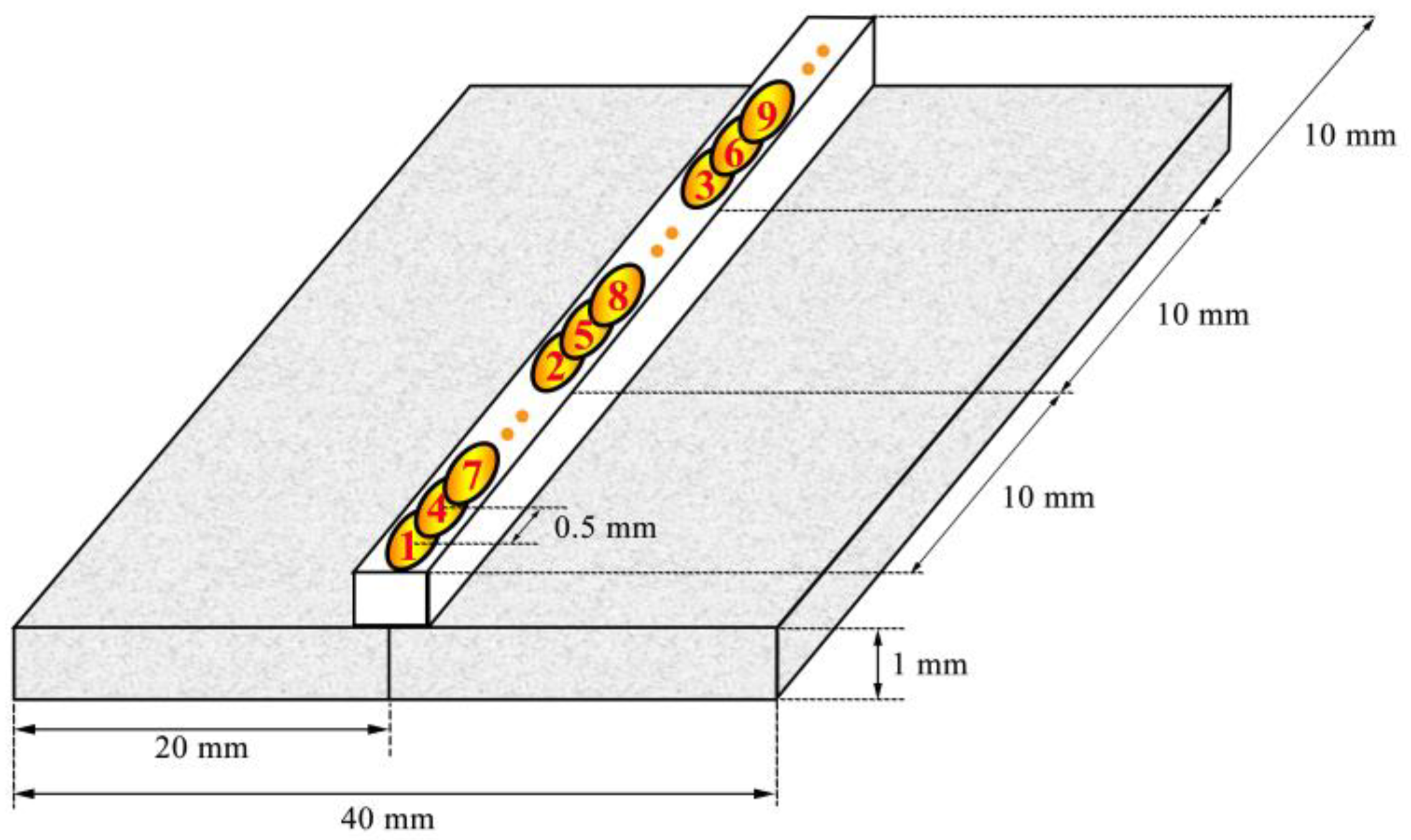
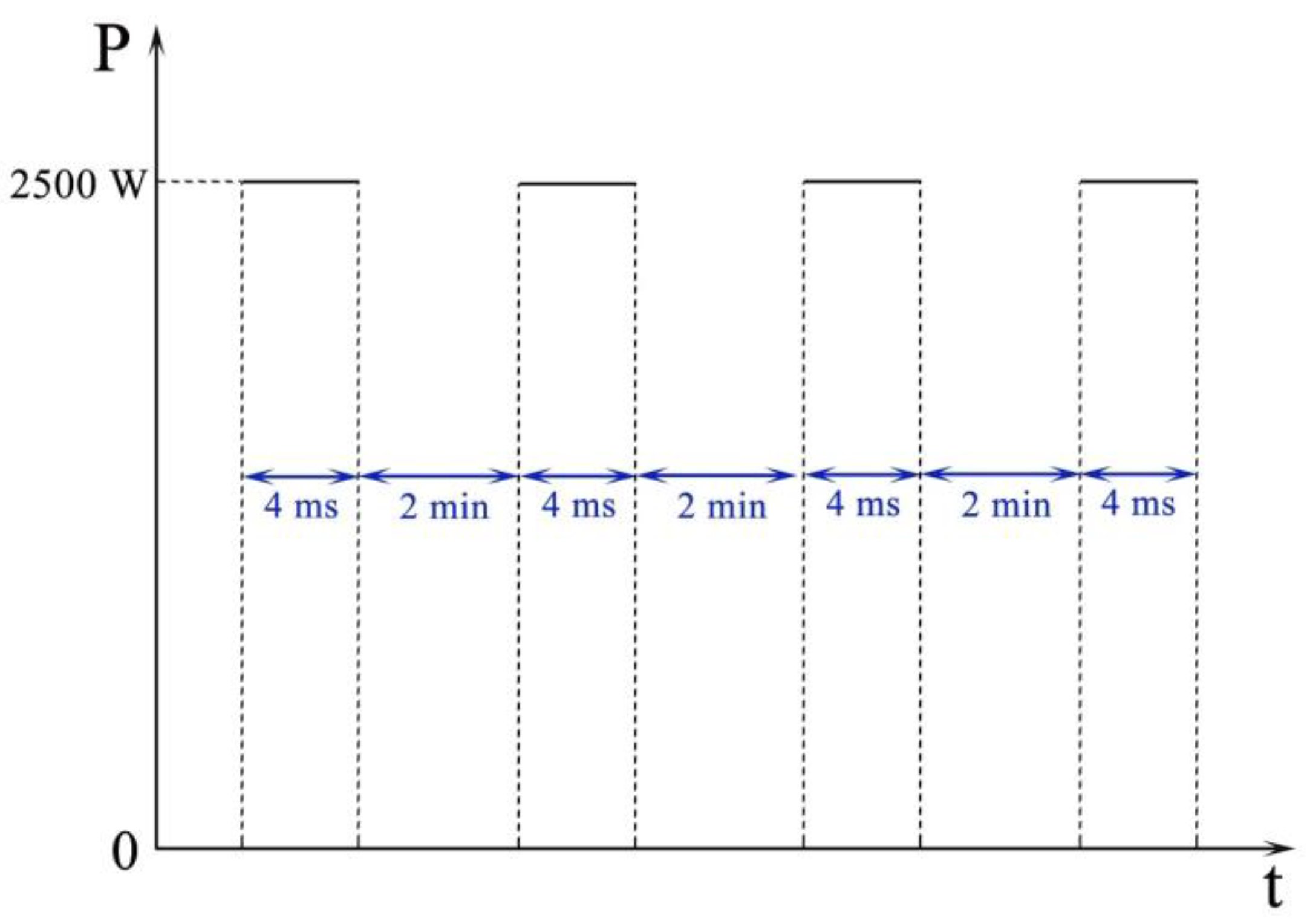
A 6 kW Nd/YAG laser (Trumpf HAAS HL3006D, Trumpf, Ditzingen, Germany) was used for the welding experiments. The focusing optic has a focal length of 223 mm and projects a laser spot with a diameter of 0.6 mm on the work piece. A laser power of 2500 W with a pulse duration of 4 ms was applied to realise full penetration. A shielding gas of argon was delivered to the work piece at a flow rate of 8 L/min. In order to compensate the material loss due to metal evaporation during the welding process, an ODS Eurofer square bar with dimensions of 30 × 1 × 1 mm3 was attached to the surface of the work piece to act as a filler material. The sheets were joined using the pattern indicated in Figure 1. Instead of moving straight in one direction, the laser beam was moved following the sequence number 1, 2, 3, etc., in order to minimise the heat effect of the laser beam on the material and therefore shorten the period of the melt pool. The distance between the centre of the adjacent spots was 0.5 mm to ensure a continuous weld, i.e., an overlap of approximately 8%. The time interval between each spot was 2 min. The pulse shape of the applied laser beam is indicated in Figure 2.
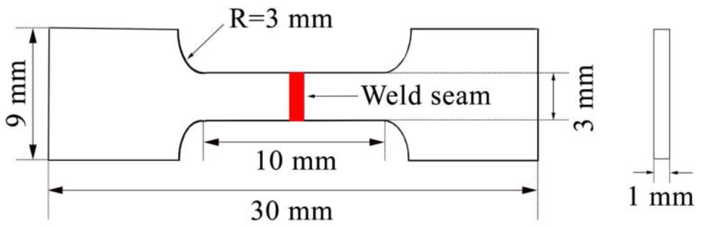
The microstructure of the joint was characterised using a JEOL 6500F scanning electron microscope (SEM, JEOL Ltd., Tokyo, Japan) and a JEM-2200FS transmission electron microscope (TEM, JEOL Ltd., Tokyo, Japan) equipped with an energy dispersive spectrometer (EDS) system. To reveal the microstructure for SEM observations, the samples were etched in a mixed solution of 5 g ferric chloride, 50 mL HCl and 100 mL water for 20 s. The TEM specimens were prepared by electropolishing disks with a diameter of 3 mm in a twin-jet electropolisher using 4% perchloric acid and 96% ethanol as the electrolyte. Vickers microhardness across the weld was measured, with a load of 0.3 kg and a step size of 0.1 mm. Flat tensile specimens were cut from the joined sample, with the weld seam located at the centre of the sample and perpendicular to the applied tensile force, as shown in Figure 3. The specimens had a width of 3 mm, thickness of 1 mm and gauge length of 10 mm. The tensile properties were determined using an Instron 5500R machine, with a nominal strain rate of 2.5 × 10⁻⁴ s−1 at room temperature. According to ISO 6892-1:2009(E) [9], the elongation A is measured from the following equation:
where L0 is the original gauge length and Lu is the final gauge length after fracture.
3. Results and Discussion
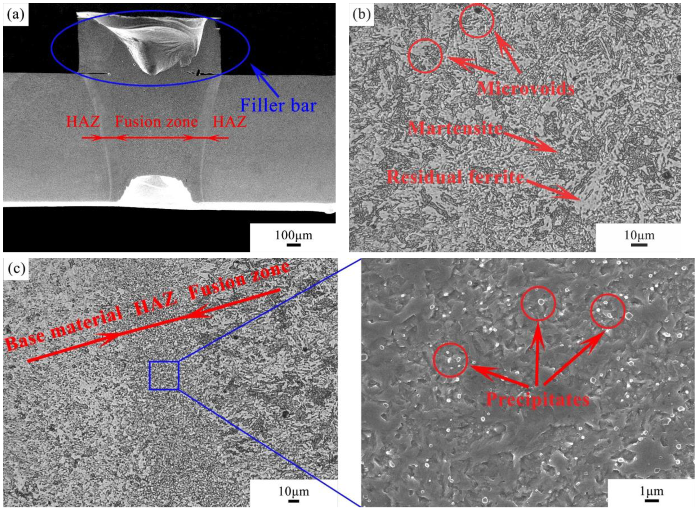
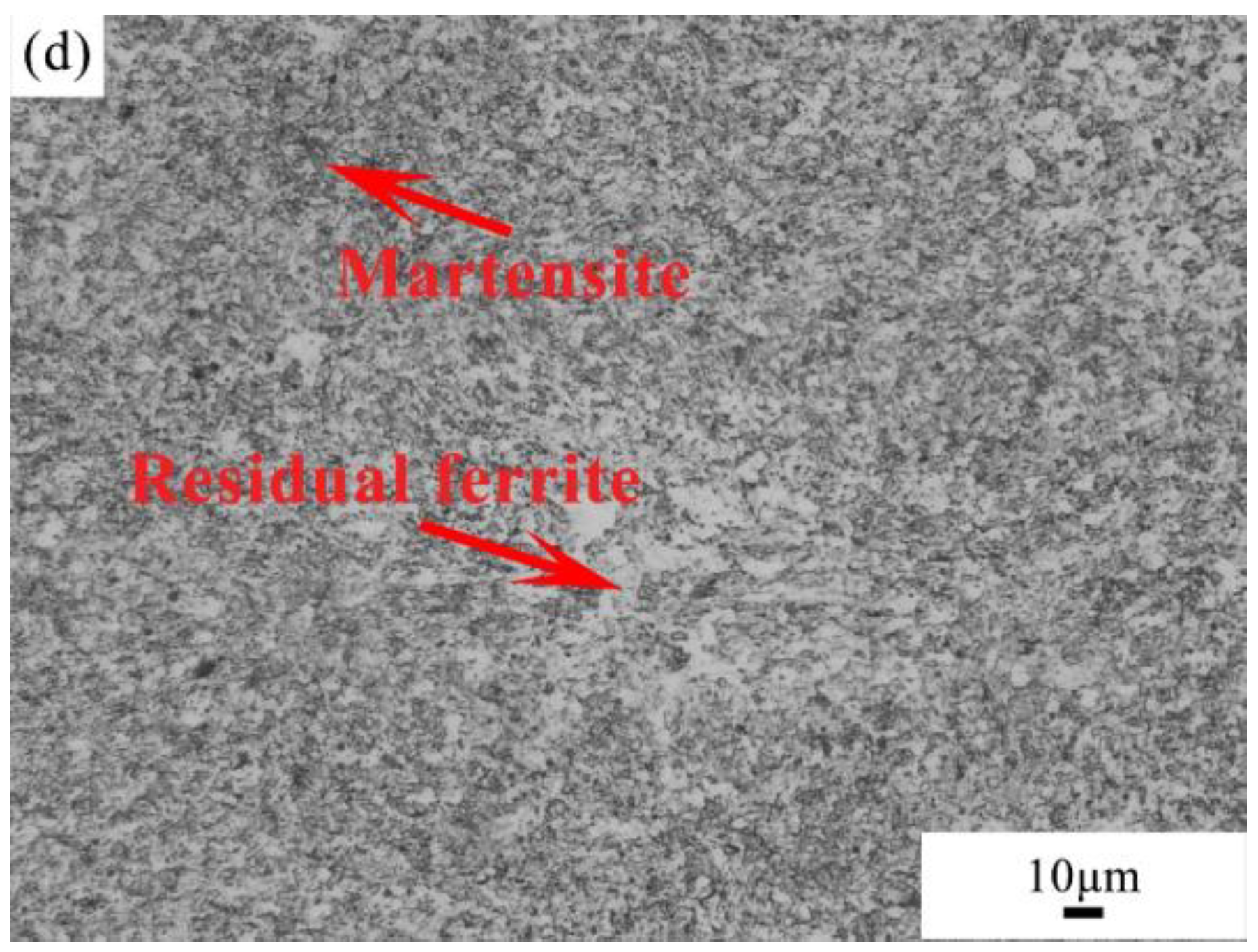
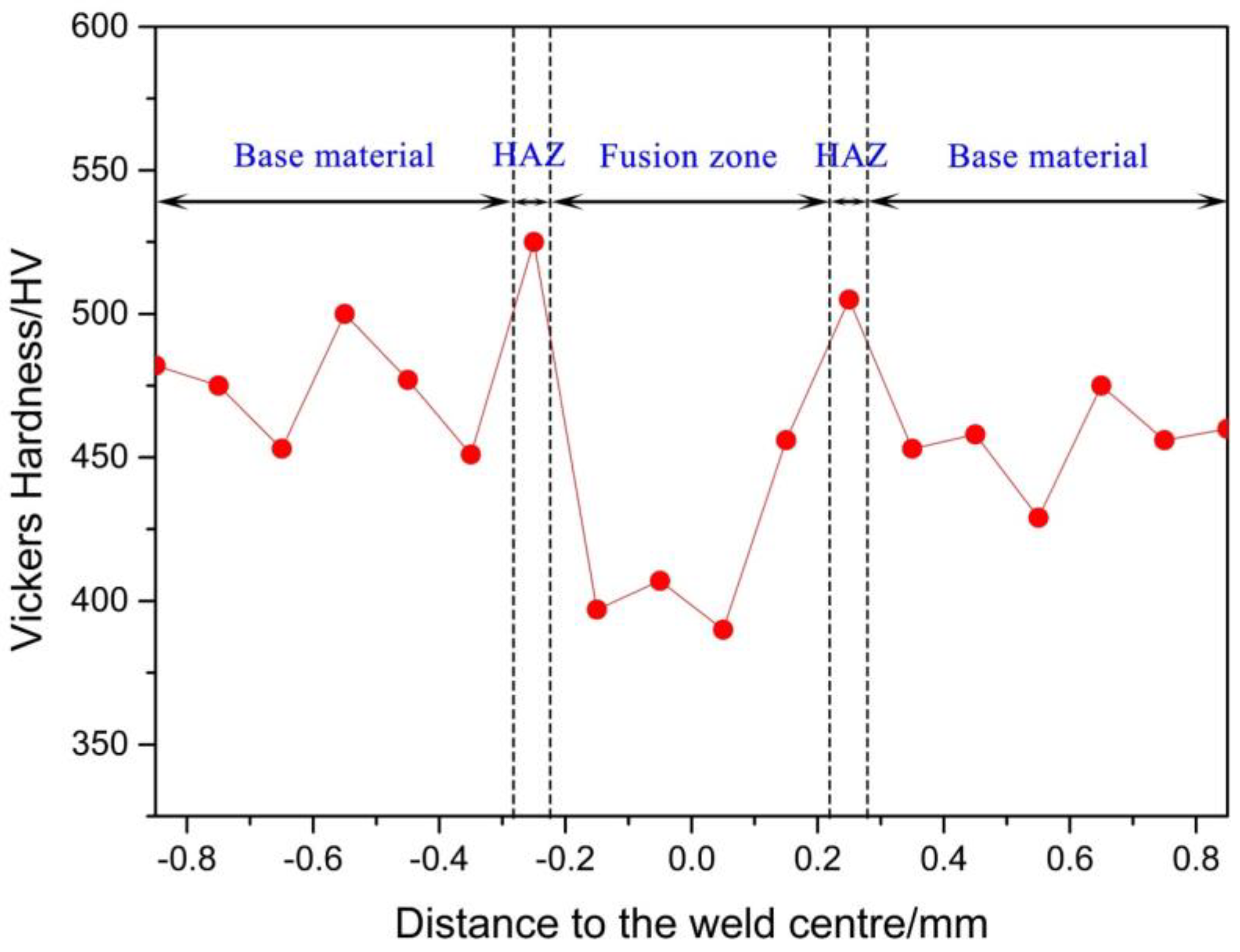
An SEM image of the weld seam is shown in Figure 4a. The laser beam penetrates the plate during the welding process, causing part of the material to evaporate, and therefore a minor material loss from the bottom surface. Severe material losses were observed in the filler bar, in other words, the material loss in the top surface of the specimen is compensated by the filler material. The microstructure of the fusion zone consists of elongated structures with microvoids, as seen in Figure 4b, and contains both martensite grains (dark region) and ferrite grains (bright region). One possible reason for the formation of this microstructure is that since the ferrite–austenite transformation is a diffusion-controlled process, the rapid heating and solidification do not offer sufficient time to complete the phase transformation [10]. As a result, residual ferrite is observed in the fusion zone. The heat-affected zone (HAZ) has a width of around 0.06 mm. The grain size of the HAZ is smaller compared with the base material showing a refinement effect (Figure 4c). Precipitates rich in Fe, Cr and C, determined by EDS analysis, are found to be decorating the grain boundaries in the material. The microstructure of the base material region can be seen in Figure 4d. It is also a dual phase microstructure, consisting of martensite and residual ferrite. The hardness profile of the cross-section of the weld is shown in Figure 5. The average microhardness of the base material is approximately 465 HV. There is a decrease of around 70 HV in the weld centre compared with the base material due to grain growth. In addition, the hardness profile shows a slight increase in the HAZ due to a finer grain size compared with the base material.
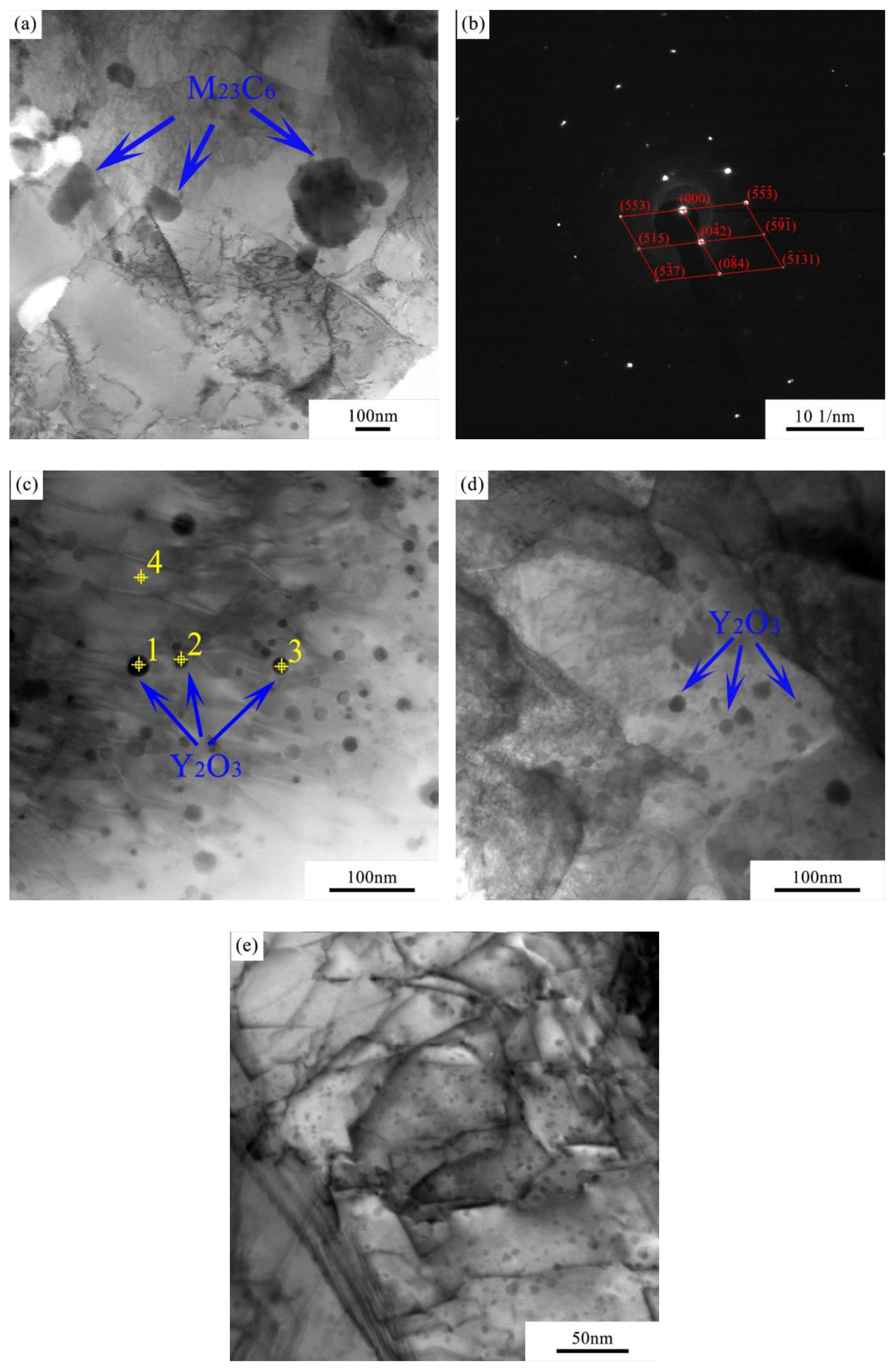
To further investigate the microstructural features in the weld seam, samples taken from the fusion zone and base material were characterised by TEM. As can be seen in Figure 6a, a large number of M23C6 (M = Fe and Cr) carbides, confirmed by the diffraction pattern shown in Figure 6b, are found to be present in the fusion zone. Meanwhile, finely dispersed Y2O3 nanoparticles, confirmed by EDS, are observed in both samples (Figure 6c,d). The chemical composition of the nano-oxides in Figure 6c was determined by EDS, as shown in Table 2. It can be seen that besides Y and O, there is an increase of V in the oxide particles compared with the base material. It is possible that V combines with Y2O3 during the mechanical alloying process. Similar results were obtained by References [11] and [12]. The particle size does not show a significant difference between the fusion zone and base material, which varies within a range of 1–30 nm. In addition, no evident clustering of Y2O3 is observed in the microstructure of the fusion zone, which is crucial for the mechanical properties of the joint. A high density of dislocations is evident in the microstructure of the base material (Figure 6e), probably due to the mechanical alloying process. It is also worth noting that Y2O3 particles are not homogeneously distributed in the steel matrix. The non-homogeneity of Y2O3 particles in the powder metallurgy-prepared ODS steels was reported by several authors [13,14,15]. Even though high-energy ball milling is known to be efficient to produce powders with nano-scale oxide particles, a perfect solid solution of ODS powders is difficult to achieve.
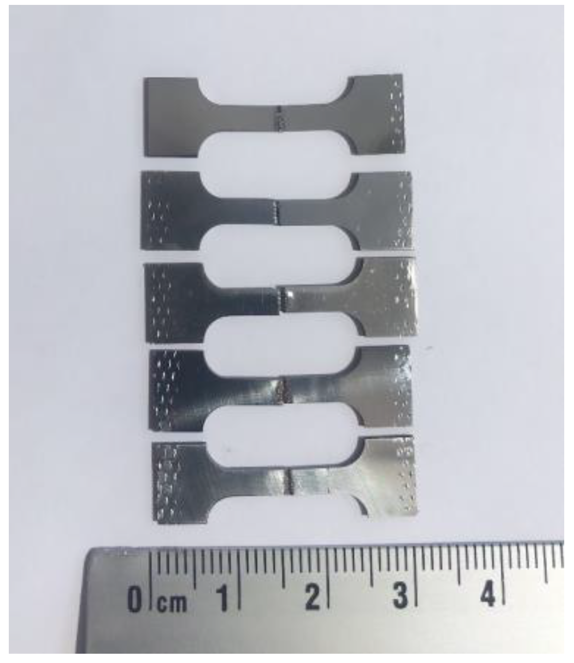
The tensile properties of the as-joined specimen are shown in Table 3. The standard deviations of the tensile properties are relatively high. This could be ascribed to the welding defects, which can act as preferential sites for crack initiation. As a result, specimens having a larger number of defects such as microvoids will have a significantly lower strength and ductility. All of the tested specimens fractured in the fusion zone (Figure 7), indicating the weakest point of the joint due to the material loss, microvoids and grain growth. It is worth mentioning that in case the actual cross-sectional area is considered, the strength of the specimen will be increased by approximately 25% compared with the values in the table. The tensile properties of the base material obtained from our previous study are also listed in this table [8]. It can be seen that the strength and elongation of the joined specimen are slightly compromised compared with the base material. This result agrees with the softening weld metal in the fusion zone indicated by the hardness profile.
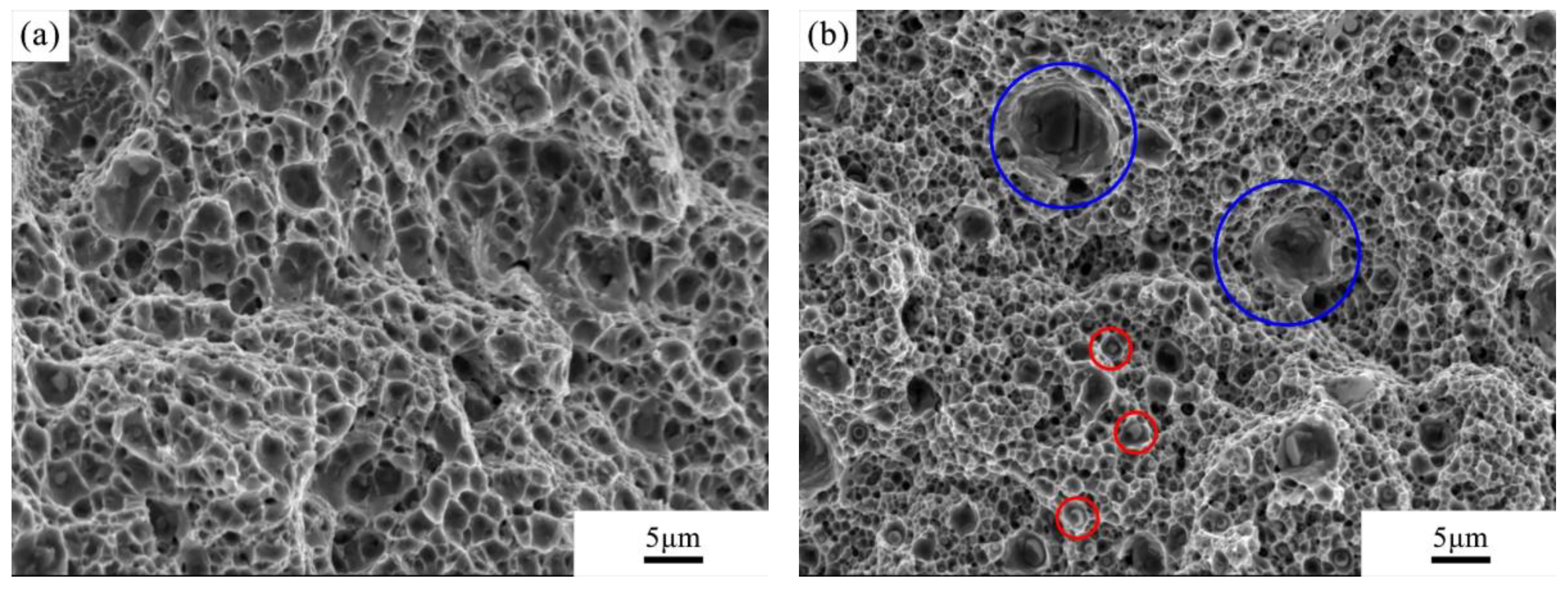
The fractures of two specimens from the tensile testing were analysed by SEM (Figure 8). One specimen (Figure 8a) has higher tensile strength and elongation than the other (Figure 8b). It can be seen that the fracture in Figure 8a shows numerous dimple features, indicating a typical ductile fracture mode. The fracture in Figure 8b also shows a ductile mode but with smaller and shallower dimples, indicating a lower ductility. It is worth noting that large precipitates (red cycles) and microvoids (blue cycles) were observed at the fracture surface. As mentioned above, coarse M23C6 precipitates and microvoids can act as preferential sites for crack initiation due to the stress concentration [16], leading to decreased strength and ductility.
The period of melt pool during fusion welding is crucial for retaining the microstructure and mechanical properties of ODS steel joints. Lemmen et al. [6] studied continuous laser beam welding on PM1000 with a range of welding parameters. Yttrium oxide agglomeration was found in all conditions, leading to a reduction in the strength of the weld. In comparison, in this study, the time spent at high temperatures was limited significantly to avoid undesirable metallurgical structures and hence poor mechanical properties. Pulsed laser beam welding shows potential to be used as a welding technique for ODS steels, considering the advantages of minor microstructural degradation and relatively good mechanical properties of the joints obtained. To the best knowledge of the authors, this is the first study concerned with pulsed laser beam welding for the joining of ODS steels. This study can contribute to the application of laser beam welding on ODS steels and improve the efficiency and flexibility of welding.
4. Conclusions
ODS Eurofer was welded successfully with a pulsed laser beam spot welding technique with a pattern designed to minimise the local heat build-up. The fusion zone consists of an elongated and dual phase microstructure. The HAZ has a width of around 0.06 mm, with refined grains. The microhardness profile shows softening in the fusion zone and hardening in the HAZ compared with the base material. The TEM observation shows that the nanoprecipitates are finely distributed in the fusion zone. The tensile properties of the joints are slightly lower than those of the base material due to the material loss, microvoids and grain growth in the fusion zone. The fracture analysis shows well-defined dimple features. Our study shows that pulsed laser beam welding is a suitable technique to join ODS Eurofer steel, with acceptable microstructure features and mechanical properties.
Author Contributions
Conceptualization, I.R.; methodology, J.F. and I.R.; software, J.v.S. and V.B.; validation, J.F.; formal analysis, J.F.; investigation, J.F. and J.v.S.; resources, J.v.S. and H.B.; data curation, J.F.; writing—original draft preparation, J.F.; writing—review and editing, I.R. and M.H.; visualization, M.H.; supervision, I.R. and M.H.; project administration, I.R. and M.H.; funding acquisition, I.R. and M.H. All authors have read and agreed to the published version of the manuscript.
Funding
This research was carried out under project number T16010f in the framework of the Partnership Program of the Materials innovation institute M2i (www.m2i.nl) and the Netherlands Organisation for Scientific Research (www.nwo.nl). The authors thank the industrial partner Nuclear Research and Consultancy Group (NRG) in this project for the financial support.
Conflicts of Interest
The authors declare no conflict of interest.
References
- Gwon, J.H.; Kim, J.H.; Lee, K.A. Effect of cryomilling on the high temperature creep properties of oxide dispersion strengthened steels. Mater. Sci. Eng. A 2016, 676, 209–215. [Google Scholar] [CrossRef]
- Nagini, M.; Vijay, R.; Rajulapati, K.V.; Reddy, A.; Sundararajan, G. Microstructure–mechanical property correlation in oxide dispersion strengthened 18Cr ferritic steel. Mater. Sci. Eng. A 2017, 708, 451–459. [Google Scholar] [CrossRef]
- McKimpson, M.; O’Donnell, D. Joining ODS materials for high-temperature applications. JOM 1994, 46, 49–51. [Google Scholar] [CrossRef]
- Kelly, T. Pulsed YAG laser welding of ODS alloys. AIP Conf. Proc. 1979, 50, 215–220. [Google Scholar]
- Molian, P.; Yang, Y.; Patnaik, P. Laser welding of oxide dispersion-strengthened alloy MA754. J. Mater. Sci. 1992, 27, 2687–2694. [Google Scholar] [CrossRef]
- Lemmen, H.; Sudmeijer, K.; Richardson, I.; Van der Zwaag, S. Laser beam welding of an Oxide Dispersion Strengthened super alloy. J. Mater. Sci. 2007, 42, 5286–5295. [Google Scholar] [CrossRef] [Green Version]
- Liang, S.; Lei, Y.; Zhu, Q. The filler powders laser welding of ODS ferritic steels. J. Nucl. Mater. 2015, 456, 206–210. [Google Scholar] [CrossRef]
- Fu, J.; Brouwer, J.; Richardson, I.; Hermans, M. Effect of mechanical alloying and spark plasma sintering on the microstructure and mechanical properties of ODS Eurofer. Mater. Des. 2019, 177, 107849. [Google Scholar] [CrossRef]
- International Organization for Standardization. Metallic Materials-Tensile Testing-Part 1: Method of Test at Room Temperature; ISO EN. 6892-1; International Organization for Standardization: Geneva, Switzerland, 2009. [Google Scholar]
- Yan, J.; Gao, M.; Zeng, X. Study on microstructure and mechanical properties of 304 stainless steel joints by TIG, laser and laser-TIG hybrid welding. OptLE 2010, 48, 512–517. [Google Scholar] [CrossRef]
- Aleev, A.; Iskandarov, N.; Klimenkov, M.; Lindau, R.; Möslang, A.; Nikitin, A.; Rogozhkin, S.; Vladimirov, P.; Zaluzhnyi, A. Investigation of oxide particles in unirradiated ODS Eurofer by tomographic atom probe. J. Nucl. Mater. 2011, 409, 65–71. [Google Scholar] [CrossRef]
- Klimenkov, M.; Lindau, R.; Möslang, A. New insights into the structure of ODS particles in the ODS-Eurofer alloy. J. Nucl. Mater. 2009, 386, 553–556. [Google Scholar] [CrossRef]
- Kishimoto, H.; Alinger, M.J.; Odette, G.R.; Yamamoto, T. TEM examination of microstructural evolution during processing of 14CrYWTi nanostructured ferritic alloys. J. Nucl. Mater. 2004, 329–333, 369–371. [Google Scholar] [CrossRef]
- Sallez, N.; Hatzoglou, C.; Delabrouille, F.; Sornin, D.; Chaffron, L.; Blat-Yrieix, M.; Radiguet, B.; Pareige, P.; Donnadieu, P.; Bréchet, Y. Precipitates and boundaries interaction in ferritic ODS steels. J. Nucl. Mater. 2016, 472, 118–126. [Google Scholar] [CrossRef]
- Auger, M.A.; De Castro, V.; Leguey, T.; Muñoz, A.; Pareja, R. Microstructure and mechanical behavior of ODS and non-ODS Fe-14Cr model alloys produced by spark plasma sintering. J. Nucl. Mater. 2013, 436, 68–75. [Google Scholar] [CrossRef] [Green Version]
- Wang, S.; Chang, X.; Key, J. New insight into high-temperature creep deformation and fracture of T92 steel involving precipitates, dislocations and nanovoids. Mater. Charact. 2017, 127, 1–11. [Google Scholar] [CrossRef]
Figure 1.
Schematic illustration of welding strategies.

Figure 2.
Pulse shape of the applied laser beam.

Figure 3.
Sketch showing the shape and dimensions of the tensile samples.

Figure 4.
SEM morphologies and microhardness of the weld seam with the filler material (P = 2500 W, t = 4 ms): (a) morphology of the weld seam, (b) weld centre, (c) heat-affected zone (HAZ) and (d) base material.
Figure 4.
SEM morphologies and microhardness of the weld seam with the filler material (P = 2500 W, t = 4 ms): (a) morphology of the weld seam, (b) weld centre, (c) heat-affected zone (HAZ) and (d) base material.


Figure 5.
Microhardness profile along the cross-section of the weld.

Figure 6.
TEM images of the microstructural features: (a) M23C6 carbides in the fusion zone, (b) diffraction pattern of M23C6 carbides, (c) Y2O3 nanoparticles in the fusion zone, (d) Y2O3 nanoparticles in the base material and (e) high-density dislocation.
Figure 6.
TEM images of the microstructural features: (a) M23C6 carbides in the fusion zone, (b) diffraction pattern of M23C6 carbides, (c) Y2O3 nanoparticles in the fusion zone, (d) Y2O3 nanoparticles in the base material and (e) high-density dislocation.

Figure 7.
Fractured specimens after tensile testing.

Figure 8.
SEM micrographs of the fractures for specimens after tensile testing: (a) one specimen with higher tensile strength and elongation and (b) one specimen with lower tensile strength and elongation.
Figure 8.
SEM micrographs of the fractures for specimens after tensile testing: (a) one specimen with higher tensile strength and elongation and (b) one specimen with lower tensile strength and elongation.


Table 1.
Chemical composition of oxide dispersion-strengthened (ODS) Eurofer and the powder size used in this study.
Table 1.
Chemical composition of oxide dispersion-strengthened (ODS) Eurofer and the powder size used in this study.
| Element | Cr | W | Mn | V | Ta | Y2O3 | Fe |
|---|---|---|---|---|---|---|---|
| wt.% | 9.0 | 1.1 | 0.4 | 0.2 | 0.12 | 0.3 | Bal. |
| Size/µm | 38–45 | 45–75 | 45–115 | Max 45 | Max 75 | 0.025–0.05 | Max 60 |
Table 2.
Chemical composition of the points indicated in Figure 6c.
Table 2.
Chemical composition of the points indicated in Figure 6c.
| Element (wt.%) | Cr | W | Mn | V | Ta | Y | Fe |
|---|---|---|---|---|---|---|---|
| 1 | 10.7 | 0 | 0.53 | 0.61 | 0.43 | 6.33 | Bal. |
| 2 | 10.05 | 0.23 | 0.51 | 0.67 | 0.07 | 4.91 | Bal. |
| 3 | 10.68 | 0.48 | 0.27 | 0.49 | 0 | 7.25 | Bal. |
| 4 | 9.56 | 1.01 | 0.45 | 0.22 | 0 | 0.16 | Bal. |
Table 3.
Tensile testing results of the joined material and base material.
| Tensile Properties | Tensile Strength/MPa | Yield Strength/MPa | Elongation/% |
|---|---|---|---|
| As-joined specimen | 1004.8 ± 154.1 | 821.0 ± 143.2 | 5.54 ± 1.72 |
| Base material | 1301.2 ± 144.5 | 923.7 ± 183.1 | 6.86 ± 2.69 |
© 2020 by the authors. Licensee MDPI, Basel, Switzerland. This article is an open access article distributed under the terms and conditions of the Creative Commons Attribution (CC BY) license (http://creativecommons.org/licenses/by/4.0/).
Share and Cite
MDPI and ACS Style
Fu, J.; van Slingerland, J.; Brouwer, H.; Bliznuk, V.; Richardson, I.; Hermans, M. Applicability Study of Pulsed Laser Beam Welding on Ferritic–Martensitic ODS Eurofer Steel. Metals 2020, 10, 736. https://doi.org/10.3390/met10060736
AMA Style
Fu J, van Slingerland J, Brouwer H, Bliznuk V, Richardson I, Hermans M. Applicability Study of Pulsed Laser Beam Welding on Ferritic–Martensitic ODS Eurofer Steel. Metals. 2020; 10(6):736. https://doi.org/10.3390/met10060736
Chicago/Turabian StyleFu, Jia, Jurriaan van Slingerland, Hans Brouwer, Vitaliy Bliznuk, Ian Richardson, and Marcel Hermans. 2020. "Applicability Study of Pulsed Laser Beam Welding on Ferritic–Martensitic ODS Eurofer Steel" Metals 10, no. 6: 736. https://doi.org/10.3390/met10060736
Note that from the first issue of 2016, this journal uses article numbers instead of page numbers. See further details here.