Fault Recovery Path Analysis of a Software Dynamic Image Based on a Fuzzy Control Algorithm

1
College of Science and Technology, Xinjiang Agricultural University, Urumqi 830091, China
2
Faculty of Electronic Information and Electrical Engineering, Dalian University of Technology, Dalian 116024, China
Symmetry 2020, 12(6), 897; https://doi.org/10.3390/sym12060897
Submission received: 20 April 2020
/
Revised: 6 May 2020
/
Accepted: 7 May 2020
/
Published: 1 June 2020
(This article belongs to the Special Issue Mathematical Modeling and Computational Methods in Science and Engineering II)
Abstract
:In order to improve the ability of software dynamic image fault detection, a software dynamic image fault recovery path detection algorithm based on a fuzzy control algorithm is proposed. A software dynamic image fault signal model of a software dynamic image fault was constructed by adopting an embedded feature extraction and a fuzzy control algorithm, and the dynamic image fault signal of the embedded software under the multi-load was subjected to frequency spectrum decomposition and blind source separation. The method comprises the following steps: (1) carrying out noise reduction processing on a software dynamic image fault signal by adopting a multi-dimensional wavelet decomposition method, (2) carrying out wavelet entropy feature extraction on the software dynamic image fault signal of the noise reduction output, and (3) combining the wavelet structural feature recombination method to carry out the recombination of the software dynamic image fault feature. The high-order spectral characteristic of the software dynamic image fault signal was extracted and the high-order spectral characteristic of the extracted embedded software dynamic image fault recovery path was automatically matched, and the automatic identification and detection of the fault part of the software dynamic image was realized.
1. Introduction
It is necessary to effectively detect and diagnose software dynamic image faults in embedded software, improve the stable operation ability of embedded software equipment, ensure the output stability of embedded software, and study the software dynamic image fault detection methods used in electric embedded software equipment. This is of great significance in ensuring the safe and stable operation of embedded software networks [1].
An embedded software system is mainly composed of three components: program writing, program control, and program compilation. The software dynamic image fault detection methods of each part are different. The essence of software dynamic image fault detection is to tap the software dynamic image fault information characteristic of the embedded software, to combine the information characteristic correlation excavation and the signal detection method, and to carry out sensing fusion analysis and feature extraction of the software dynamic image fault signal according to the difference feature quantity of the extracted software dynamic image fault information. The accurate positioning and identification of the software dynamic image fault part is thus realized, and the accuracy of the software dynamic image fault detection can be improved [2]. In the traditional method, the detection method for software dynamic image faults is mainly based on image-processing technology. The invention relates to a software dynamic image fault detection method based on signal-processing technology, and software dynamic image fault detection based on a large-data-analysis technology [3]. By combining embedded software composite imaging and signal-detection technology, the software dynamic image fault detection of embedded software is realized, and a certain detection performance is obtained. In the literature [4], a software dynamic image fault detection method based on fractional Fourier time-frequency coupling was proposed, and the automatic detection of the software dynamic image fault was carried out in combination with the machine learning algorithm. The detection convergence was improved, but the calculation cost of the algorithm was large and the real-time performance was not good. A software dynamic image fault detection algorithm based on an improved correlation rule feature analysis method was proposed in Reference [5], where the high-order spectral characteristic of the embedded software monitoring signal was extracted to realize the detection of the software dynamic image fault characteristic. The defect of the software dynamic image fault information being redundant and the error being large was overcome. A software dynamic image fault detection model based on phase space reconstruction was proposed in Reference [4], where the software dynamic image fault signal was simulated into an amplitude-modulated signal, the beam directivity characteristic of the software dynamic image fault signal was obtained, and a multidimensional state space was created. The software dynamic image fault detection of embedded software was realized by a non-linear system, and the accuracy of the software dynamic image fault detection for the large-scale dataset was not good [6].
Aiming to resolve the above problems, this paper proposes a software dynamic image fault recovery path detection algorithm based on a fuzzy control algorithm. The method described in this paper has the characteristics of high convergence and good real-time performance. It realizes the high-precision detection of a software dynamic image and effectively reduces the error. First, a software dynamic image fault signal model of a software dynamic image fault is was constructed by using embedded feature extraction and a fuzzy control algorithm, and the multidimensional wavelet decomposition method was used to reduce the noise of the software dynamic image fault signal. Finally, simulation experiments were carried out to demonstrate the superior performance of this method in improving software dynamic image fault detection capability.
2. Software Dynamic Image Fault Sample Information Acquisition and Preprocessing
2.1. Software Dynamic Image Fault Code Detects Sample Information Acquisition
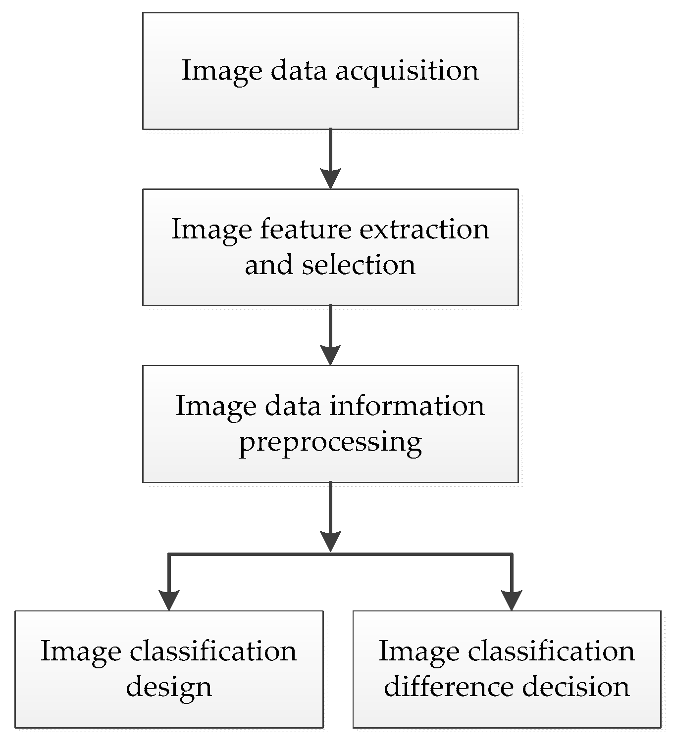
In order to realize the effective detection and diagnosis of software dynamic image faults in embedded software, software dynamic image fault data acquisition and signal extraction and analysis are the first step [7]. In embedded software, the feature of the dynamic image is based on similar high-dynamic information and spatial dimension features reflected by the same type of pixels under the same conditions. The classification of dynamic image features in embedded software is the basis of dynamic image feature extraction. The process of image pixel feature classification in embedded software is divided into two stages: design and decision-making. In the design stage, the pixel information that can be resolved is analyzed, designed, and calculated via sample analysis. In the decision-making stage, the calculated pixel information that cannot be resolved is classified. The dynamic image feature classification process for embedded software is shown in Figure 1.
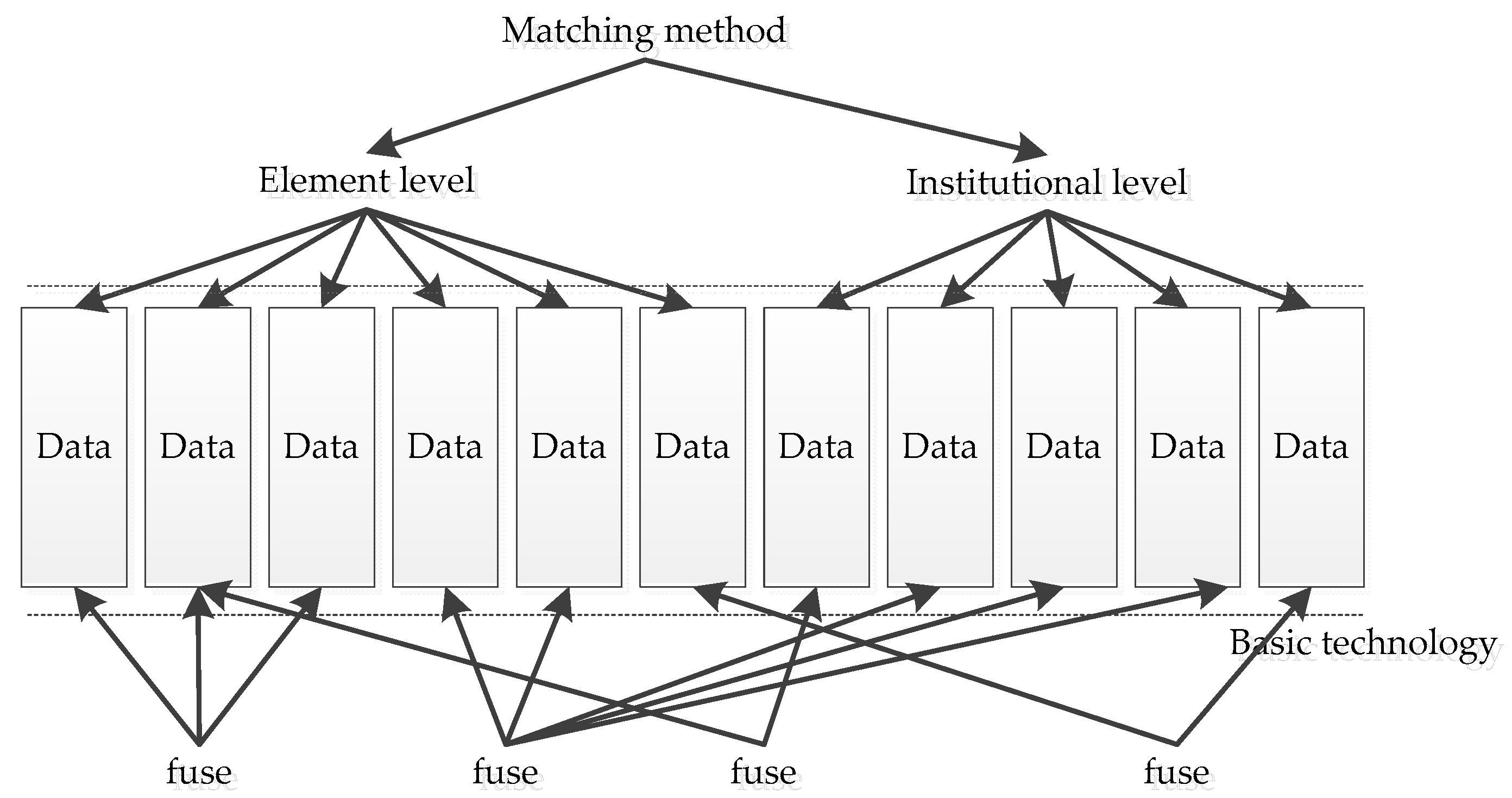
In embedded software, image data need to be normalized to reduce the data noise of the embedded network and enhance the image data signal. After dynamic image feature normalization processing, various mathematical transformations must be carried out on the image data information. The most commonly used is wavelet transform, which is a more suitable multidirectional texture calculation method for image data analysis in embedded software. A software dynamic image fault signal model of a software dynamic image fault was constructed using embedded feature extraction and fuzzy control algorithm, and the dynamic image fault recovery path of the software dynamic image fault feature was input into the expert system diagnosis database. With the association and intersection of large-scale data, data characteristics and real needs have changed. Data characterized by large-scale, multi-source, heterogeneous, cross-domain, cross-media, cross-language, dynamic evolution, and generalization play a more important role, and the corresponding data storage, analysis, and understanding are also facing major challenges. Big data fusion methods aim to maximize the value of big data by data association, cross, and fusion. The key to this problem is data fusion. Figure 2 shows the design of the overall model of data fusion related to this study.
The implementation principle of big data fusion methods actually refers to the centralized data repository, which is built based on the distributed file systems moosefs, mongodb database cluster, and vituoso database. They are, respectively, used to store the unstructured data downloaded from each data source, the structured data downloaded from each data source, and the data obtained after analyzing the original data, the transformed RDF data, and the newly established association relationship data through the semantic enhancement system. These data are gathered through various download components and management systems of the data aggregation module. For downloaded data, customized data analysis tools are developed to complete the transformation of data from its original form to an “attribute value” structured form, and configuration-based data conversion tools are developed. The “attribute value”, which is valuable for discovering the association between data, is extracted, and the extracted data are transformed into a consistent RDF format through necessary data merging, splitting, equivalent transformation, and other processing. The association mechanism between data is determined and, on this basis, similarity calculation, reasoning, ontology mapping, and other association discovery methods are used to increase the semantic associations between data. Finally, data are passed through a service interface module to provide external services. Big data fusion is a means of dealing with big data, and is used to discover knowledge from big data and integrate knowledge in a way that is closer to human thinking according to the semantic and logical associations of knowledge. It includes two steps: data fusion and knowledge fusion. Data fusion involves the dynamic extraction, integration, and transformation of multisource data into knowledge resources, which lays the foundation for knowledge fusion. Knowledge fusion is responsible for the different granularity understandings of the relationship between knowledge and knowledge; thus, knowledge has different levels of comprehensibility and comprehensibility so as to facilitate the interpretation of objective phenomena. Data fusion and knowledge fusion do not exist in isolation. The knowledge acquired via knowledge fusion can be used as a reference factor for data fusion to assist data fusion, and data fusion serves not only to provide integrated data for knowledge fusion, but may also have a reference role for knowledge fusion.
This process of software dynamic image fault diagnosis of embedded software is carried out by combining signal feature extraction and big data fusion methods, and a software dynamic image fault diagnosis analysis database is established [8,9,10]. The original signal is collected for software dynamic image fault detection, the laser detection method of embedded software working condition sample in the presence of software dynamic image fault state is used for beamforming processing, and the fault code sensor is used for data acquisition. The breakpoint data are collected under the software dynamic image fault condition, the software dynamic image fault data classification clustering center , is initialized to extract the software dynamic image fault spectrum feature of the embedded software, and the laser data receiving model of the embedded software under the software dynamic image fault condition is obtained as follows.
In the software dynamic image fault distribution index section of the embedded software, the phase characteristic analysis of the software dynamic image fault part is carried out [11,12], and the deviation degree S and the similarity of the independent and distributed random variable of the dynamic image fault node of the software are, respectively,
The software dynamic image fault detection fault code data under the software dynamic image fault condition is subjected to a sample regression analysis, and the correlation function of the software dynamic image fault sample characteristic data is calculated as follows.
Among these, the number of sampling points in the time domain of the software dynamic image fault feature sequence is , and the integral of correlation dimension obeys the exponential law, i.e.,
According to the software dynamic image fault code detection sample information acquisition result, the length fl between the optimal sampling points S of the software dynamic image fault signal of the software dynamic image fault is obtained [13,14], the software dynamic image fault signal length l of the software dynamic image fault is obtained as
where and are feature decomposition coefficients, is a software dynamic image fault signal, is a scale for a given wide-band high-resolution software dynamic image fault, and is the energy of a software dynamic image fault signal representing a software dynamic image failure. Statistical regression analysis is then carried out on the detection sample, pattern recognition is carried out on the software dynamic image fault signal of the software dynamic image fault, and the sensing information fusion method is combined to carry out the software dynamic image fault detection of the embedded software [15,16].
2.2. Multidimensional Wavelet Decomposition of Fault Recovery Path
In constructing a software dynamic image fault signal model of a software dynamic image fault, it is necessary to denoise and purify the signal in order to improve the software dynamic image fault detection performance. In wavelet analysis, different basis functions are obtained from the base wavelet through translation and expansion
where (a positive set of real numbers). For large values of , the basis function becomes the extended image wavelet, which is a low-frequency function; for small values of , the basis function becomes the reduced wavelet, which is a narrow high-frequency function.
The wavelet transform is defined as
The Time 2 frequency resolution of is variable; the time range of is shorter at high frequencies, and the frequency width of is narrower at low frequencies. Wavelet analysis involves decomposition of the signal into two parts: approximation and detail. Therefore, the original signal generates two signals through two complementary filters. The high-scale and low-frequency components of the signal are approximately represented, while the low-scale and high-frequency components are represented in detail. The approximation part can be decomposed into the third layer of approximation and details, and the signal can be decomposed into many low-resolution components if it is repeated in this way. The details of wavelet packet analysis can be decomposed just like the approximate part. For N-level decomposition, it will produce 2n different ways.
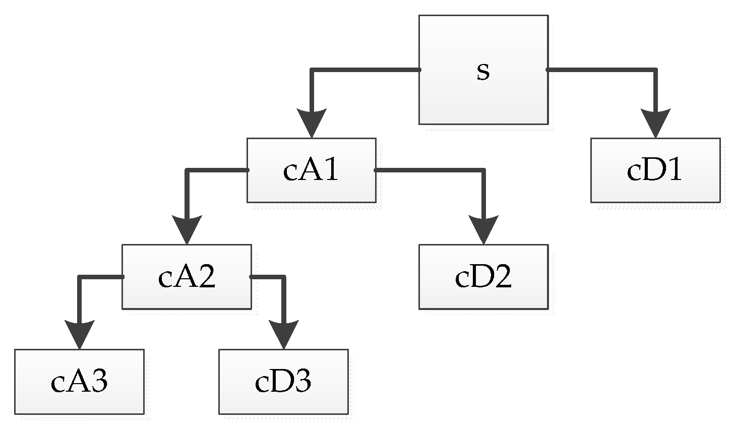
First, the signal is decomposed by wavelet as shown in Figure 3, and then the noise part is usually included in the high-frequency or low-frequency signal, and the wavelet coefficients are processed in the form of threshold value as required. Reconstruction of the signal can then achieve the purpose of noise reduction. In the figure, cA and cD are the returned low-frequency and high-frequency coefficient vectors, respectively. The decomposition relation is . To further decompose, we can further decompose the low-frequency part of into the low-frequency part of and the high-frequency part of . After the discrete wavelet transform of the sampled signal , the wavelet coefficient , which can be obtained by the properties of wavelet transform, is still composed of two parts: one is the wavelet coefficient corresponding to , and the other is the wavelet coefficient corresponding to .
When a signal with rich frequency components is used as an input to excite the system, the suppression and enhancement of each frequency component of the sampled echo signal by wavelet transform will change. Generally, it can obviously inhibit some frequency components and enhance others. Therefore, compared with the output of the normal system, the energy of signals in the same frequency band will be greatly different. It will reduce the signal energy in some frequency bands and increase the energy in other frequency bands. Therefore, the signals of each frequency component can be separated correctly.
Generally speaking, the denoising process of wavelet transform can be divided into three steps: (1) Wavelet decomposition of a multidimensional signal. Select a wavelet and determine the time level of wavelet decomposition, and then carry out multilayer wavelet decomposition to give a group of wavelet coefficients. (2) Wavelet decomposition threshold quantization of high-frequency coefficients. For each layer of high-frequency coefficients from the first layer to the nth layer, select a threshold to quantize, and find the estimated wavelet coefficients to make them as small as possible. (3) Multidimensional wavelet reconstruction, according to the low-frequency coefficients of the nth layer of wavelet decomposition and the high-frequency estimation from the first layer to the nth layer after quantization processing, carries on one-dimensional signal wavelet reconstruction.
The multiresolution analysis characteristic of a wavelet can decompose the signal at different scales, and decompose the mixed signals of different frequencies interweaved into subsignals of different frequency bands. Therefore, the signal has the ability to process according to frequency bands. Because the noise is a relatively stable Gaussian white noise, the average power of its wavelet coefficient is inversely proportional to the scale, and the amplitude of the discrete detail signal decreases with the increase of the scale. Because the wavelet transform is linear, the wavelet coefficients of the degraded signal are the sum of the wavelet coefficients of the signal and the wavelet coefficients of the noise. The discrete approximation part and the discrete detail part of the degraded signal are, respectively, the sum of the discrete approximation part and the discrete detail part after the signal transform and the discrete approximation part and the discrete detail part after the noise transform. Therefore, in the process of denoising, after using the signal and white noise in wavelet transform, their respective wavelet coefficients have different properties, which may eliminate or weaken the noise. Wavelet analysis is used in signal denoising, which is mainly reflected in the different laws of signals after wavelet transform in different resolutions, setting different threshold values in different resolutions, adjusting wavelet coefficients, and achieving the purpose of denoising. Because the length of a software dynamic image fault signal interferes with the amplitude of the signal, the length of the signal is regarded as the characteristic quantity [17,18], which can effectively feedback the software dynamic image fault category of the equipment. Assuming that the maximum energy of the software dynamic image fault signal is expressed by , λ is used as the correlation coefficient to describe the signal in order to improve the resolution and sensitivity of the software dynamic image fault signal, and the amplitude of the software dynamic image fault beam of the embedded software is taken as the effective characteristic quantity. The maximum wave peak and wave valley difference of the software dynamic image fault signal of the software dynamic image fault are calculated as
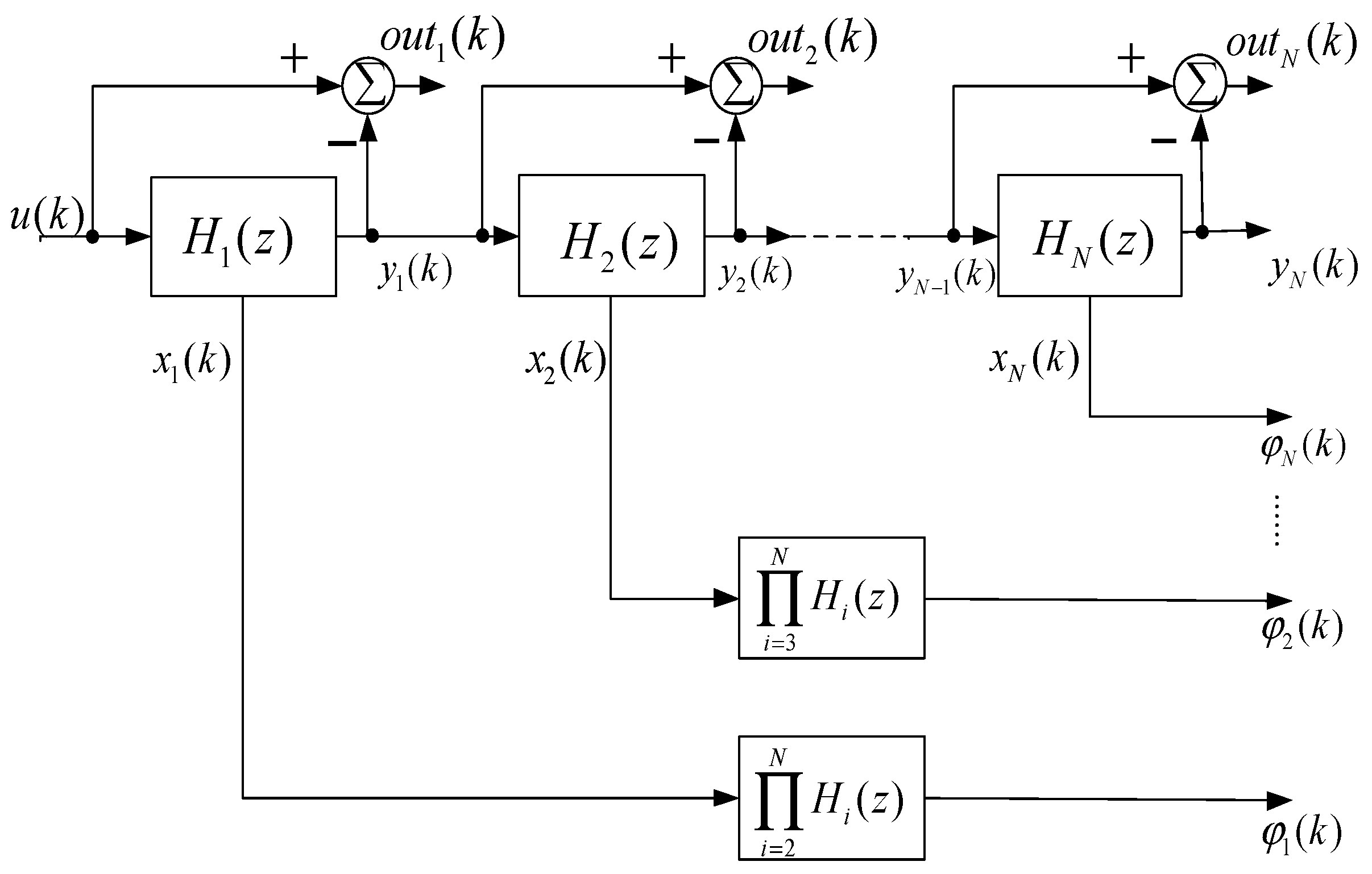
Spectrum decomposition and blind source separation of the dynamic image fault signal of embedded software s under multi-load are then carried out [19,20]. A wavelet detector is used to combine the time domain characteristic quantity and frequency domain feature quantity of the signal in order to estimate the joint parameters, as shown in Figure 4.
According to the wavelet detector designed in Figure 1, signal denoising can be carried out. The dynamic image fault signal of broadband high-resolution software is set as a set of stationary random signals [21,22,23], which is represented as the multilayer wavelet scale feature decomposition of the signal by , the joint parameter estimation of time and frequency of , and the acquisition of discrete signal . The fault code width of software dynamic image fault detection in embedded software is . The software dynamic image fault signal depth directly affects the signal amplitude, represents the depth feature, and can be used to calculate the energy distribution characteristic quantity of the software dynamic image fault signal.
The correlation relationship of each feature quantity of the software dynamic image fault signal is analyzed and compared. Combined with association rule mining and the spectrum feature extraction method, the aggregation degree of the software dynamic image fault signal in each feature quantity is obtained. According to the estimated result of signal feature quantity, the feature information of the software dynamic image fault is comprehensively reflected, and the software dynamic image fault detection is realized by combining with the fault code detection method [24,25,26].
3. Optimization of the Software Dynamic Image Fault Detection Algorithm
3.1. High-Order Spectral Feature Extraction of the Software Dynamic Image Fault Signal
The software dynamic image fault detection algorithm was optimized on the basis of using embedded feature extraction and fuzzy control algorithm to construct software dynamic image fault signal model, as well as spectrum decomposition and blind source separation processing of embedded software dynamic image fault signal under multiple loads. In this paper, a software dynamic image fault recovery path detection algorithm based on a fuzzy control algorithm is proposed. The fault code detection algorithm was used to decompose the fault output beam characteristics of the software dynamic image as follows.
A higher-order spectrum can also be called multi-spectrum. The higher-order statistics related to the higher-order spectrum are the statistics of random variables or random processes of higher order than the second-order statistics. The high-order statistics are: (1) high-order random variables (vectors), including high-order giant and high-order cumulants; (2) random processes, including high-order moments, high-order cumulants, and high-order spectra. From the statistical point of view, the statistical characteristics of random variables (vectors) with normal distribution can be completely expressed by first-order and second-order statistics. The signal processing method for higher-order statistics involves first extracting the useful information from the higher-order statistics of non-Gaussian signals, especially the information that cannot be extracted from the first- and second-order statistics. In fault signal analysis, compared with the power spectrum, the relationship with the higher-order spectrum is a direct extension of the relationship with the power spectrum. For nonlinear systems, the power spectrum is phase blind, and the output power spectrum does not contain the phase information of the system. High-order spectra are generally multidimensional complex functions, that is, they have amplitude and phase. The higher-order spectrum and the higher-order cumulant retain the nonlinear information of the system, and can be used to judge whether there is nonlinearity and the degree of nonlinearity in the system. In theory, the higher-order cumulant can completely suppress the influence of Gaussian dichroic noise. The higher-order cumulant of Gaussian process is equal to 0, even for colored Gaussian processes. This is one of the main motivations for using high-order cumulants in signal processing. The bispectra, trispectra, and higher-order spectra of Gaussian random processes are equal to 0. Thus, it is easier to extract fault features. The physical meaning of a power spectrum represents the distribution of signal energy in the frequency domain, while the physical meaning of a high-order spectrum is not as clear as that of a power spectrum. It is equivalent to the skewness of the frequency domain and the symmetrical and nonlinear characteristics of the response value signal, and more reflects the statistical process information of the signal. The higher-order statistics method is not only an important supplement to the random signal processing method based on correlation function or power spectrum, but also a means for solving many signal processing problems that the second-order statistics method cannot solve. The high-order spectrum analysis of a nonlinear signal has advantages with which spectrum analysis cannot compare. By combining the high-order statistical analysis method, the can be separated from the adaptive spectrum, the anti-sidelobe interference capability of the device software dynamic image fault detection is improved, and the high-order statistical separation can be expressed as
Self-adaptive blind separation processing is then carried out on the software dynamic image fault signal. Performing wavelet entropy feature extraction on the software dynamic image fault signal of the noise reduction output to obtain a software dynamic image fault signal parameter estimation value then gives
Two parameters, a1(t) and a2(t), for wavelet entropy estimation of software dynamic image fault characteristics are determined by the following formula.
The time-frequency decomposition of a software dynamic image fault signal is carried out via the wavelet transform method, and the correlation integral of the software dynamic image fault signal is calculated, which is expressed as follows.
In the correlation distribution source of the software dynamic image fault point, wavelet transformation is used to decompose the software dynamic image fault signal, and the time-frequency distribution function of the software dynamic image fault characteristic signal is obtained as follows.
Among these, the wavelet basis function is
According to the wavelet entropy feature extraction result of the software dynamic image fault signal, and combining the wavelet structural feature recombination method to carry out the recombination of the software dynamic image fault feature, the optimization design of the detection algorithm was carried out.
3.2. Automatic Identification and Detection of Software Dynamic Image Fault Locations
If only the signal in a certain cycle, or only a single noise signal sampling is used as the basis of fault diagnosis, the result is a lack of representativeness. Therefore, the feature parameters can be averaged after feature extraction, i.e., the parameter averaging method can be used to reduce the impact of fluctuations between and within cycles. This process is equivalent to the compression and extraction of the frequency information of the software dynamic image fault signal, highlighting the noise information and reducing the noise interference to a certain extent. Assuming that there are p distributed software dynamic image fault distribution sources, using the orthogonal characteristic of the noise subspace and the software dynamic image fault signal subspace, the base vector element of the time-frequency decomposition of the software dynamic image fault signal is obtained as follows.
In Equation (19), the “*” represents a complex resonator, and the second-order moment of the characteristic information of the dynamic image of the software is as follows.
On the basis of the covariance matrix of the frequency and amplitude modulation software’s dynamic image fault spectrum, and through singular value decomposition, the software moves. Through the above analysis, the fault code detection and identification of the software dynamic image fault position is carried out. According to the high-order spectral feature extraction results of the fault code, the automatic identification and detection of the software dynamic image fault position is realized.
4. Simulation Experiment and Performance Analysis
In order to verify the application performance of this method in software dynamic image fault detection for fault code embedded software based on the above theoretical formula, the following experiment was carried out.
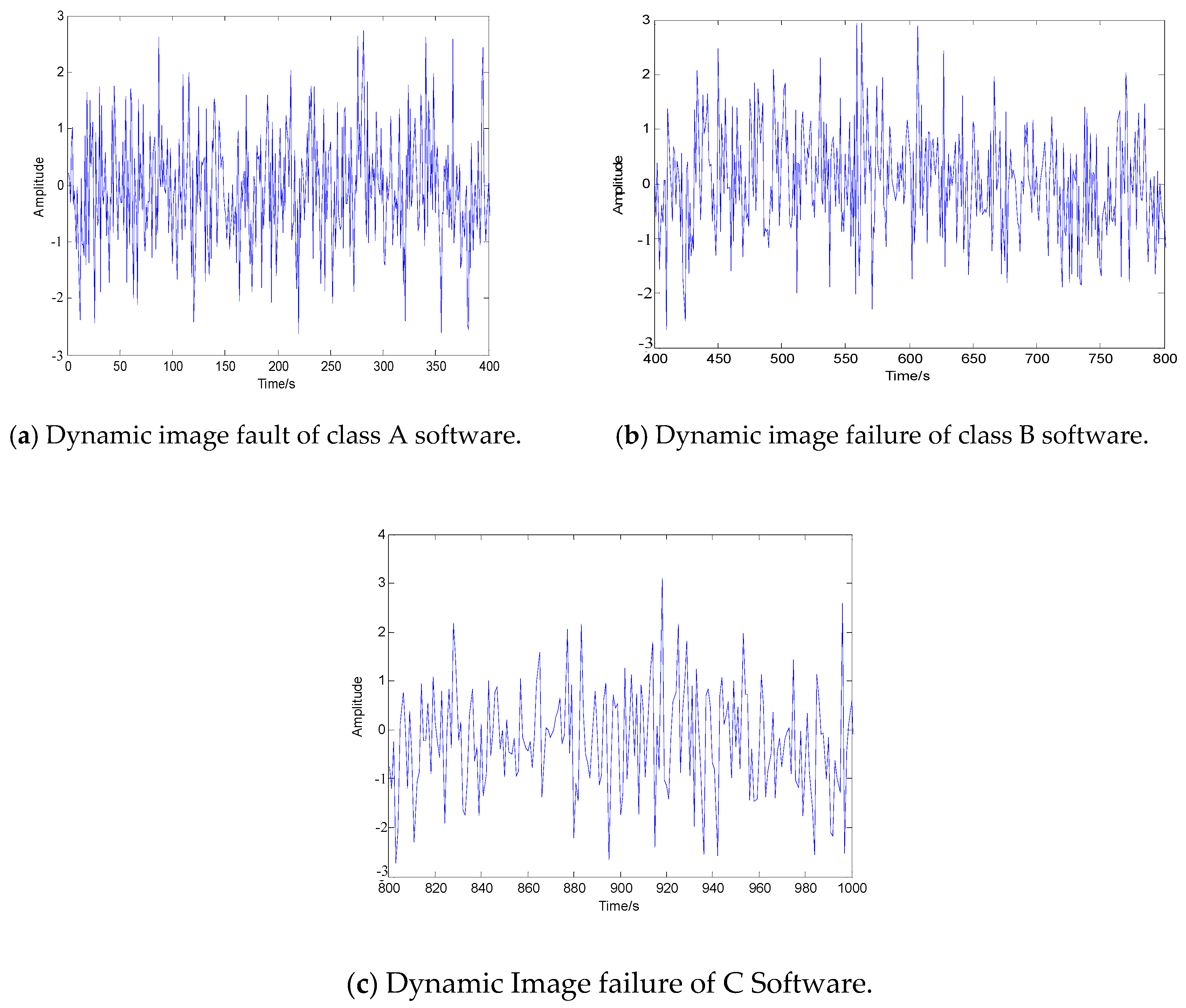
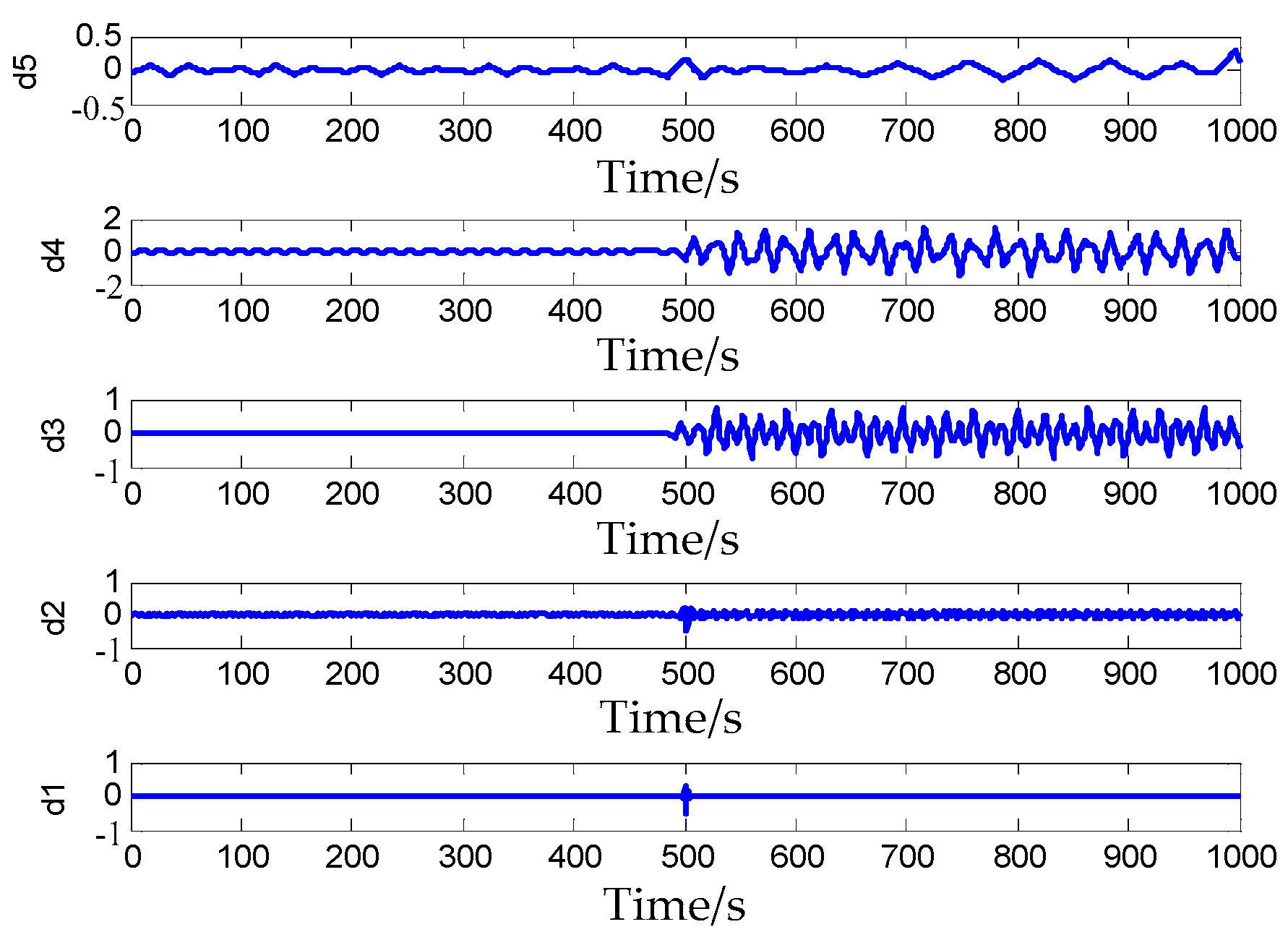
Taking the fault recovery path of the dynamic image collected in Figure 5 as the research object, the multidimensional wavelet decomposition method discussed above was used to decompose the signal at different scales, and the mixed signals composed of different frequencies interweaved together were decomposed into subsignals of different frequency segments. Different threshold values were set at different resolutions, the wavelet coefficients were adjusted, the software dynamic image fault signal is denoised, and the collected dynamic image fault signal was reconstructed by combining the wavelet structure feature reconstruction method. The dynamic image fault recovery path of the reconstructed structure is shown in Figure 6.
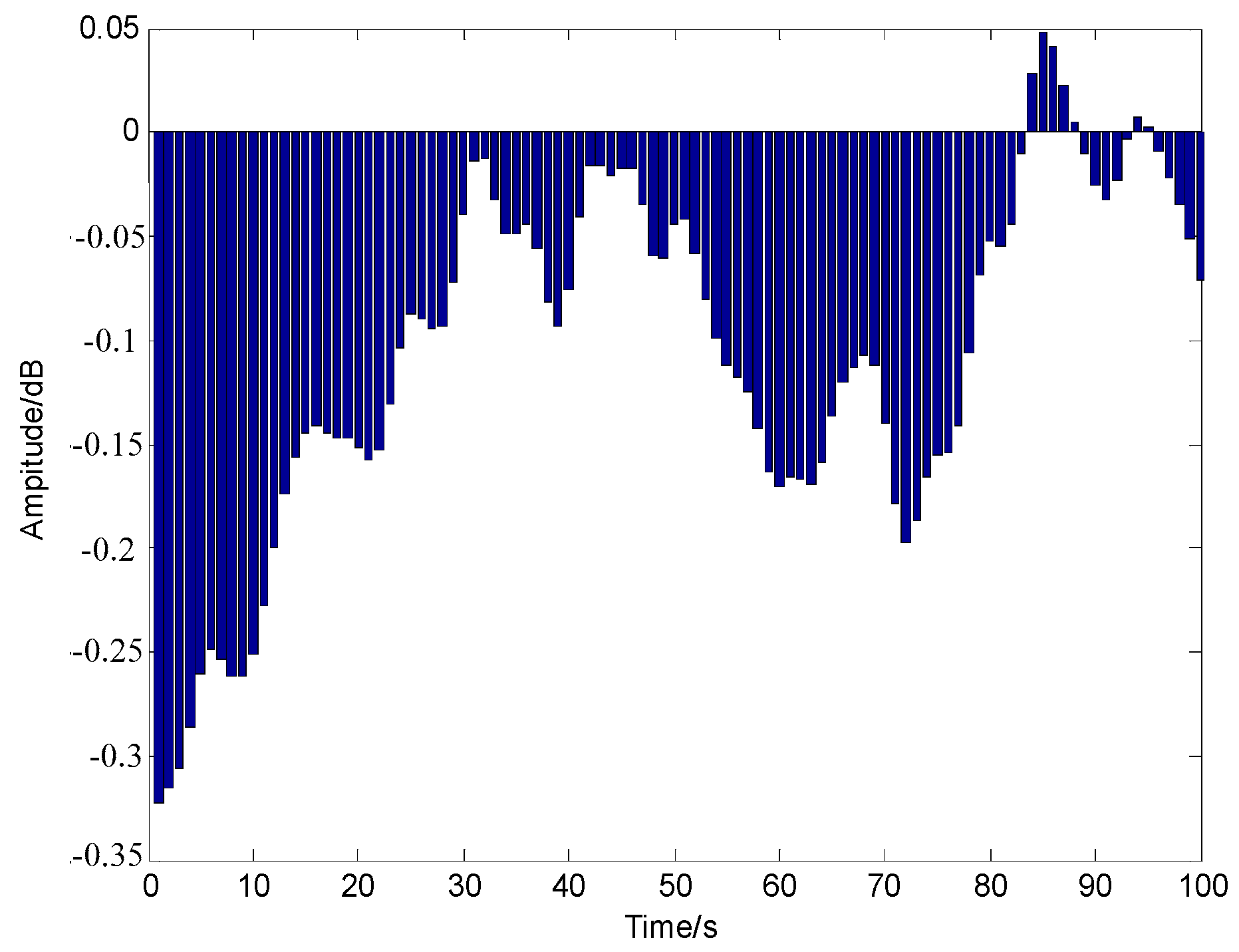
According to the recombinant result of the software dynamic image fault characteristic, the high-order spectral characteristic of the software dynamic image fault signal was extracted, the high-order statistics signal processing method of high-order spectrum was used to analyze the software dynamic image fault feature signal, and the wavelet multi-layer reconstruction was used to denoise the software dynamic image fault feature signal. The software dynamic image fault detection of the embedded software was realized, and the detection result of the software dynamic image fault part is shown in Figure 7.
Analysis of Figure 7 shows that the embedded software tested had a software dynamic image fault point at 0.84 KHz, and the location accuracy of the software dynamic image fault location was high. The performance of the software dynamic image fault detection was further tested using different methods, and the results of comparison of the detection accuracy are shown in Table 1.
The results of comparison depicted in Table 1 show that with increasing interference signal-to-noise ratio, the accuracy of three methods for dynamic image fault detection of equipment software was continuously improved. However, compared with Reference [5] and Reference [6], the accuracy of the method proposed in this paper higher. When the input SNR was 5 dB, the detection accuracy of this method was almost 100%. The average detection probability of the methods in this paper was more than 95%, while the highest detection accuracy of the other two methods was only 94.2% and 92.6%.
5. Conclusions
With the development of modern information technology, the importance of embedded software dynamic image has become more apparent. However, once a dynamic image is overloaded, it is easy for image faults to occur. In order to improve fault detection and recovery ability, this paper proposes a software dynamic image fault recovery path based on a fuzzy control algorithm, which effectively detects and diagnoses software dynamic image faults of embedded software, improves the stable operation ability of circuit equipment, and ensures the stable operation of power grids. This paper analyzed the process of dynamic image feature classification in embedded software, established the overall model of data fusion based on the embedded feature extraction, normalized the image data, reduced the data noise of embedded network, and enhanced the image data signal. Wavelet transform is a suitable method for image data analysis in embedded software. Combined with the fuzzy control algorithm, a software dynamic image fault signal model was established, and the spectrum decomposition and blind source separation were carried out for a dynamic image fault signal of embedded software under multiple loads. The simulation results showed that the method proposed in this paper had high precision and good performance for the fault detection of embedded software.
In the process of experimentation and simulation, many shortcomings and problems to be solved were also found, which will become the focus of future research work. In researching an algorithm to restrain premature convergence, the fuzzy logic controller needs more input variables and the fuzzy rules are more complex. Therefore, there is no obvious advantage to the algorithm in solving problems with too many variables and high precision requirements, and the convergence speed of the algorithm needs to be further improved while maintaining the diversity of the population. When the image was restored in block mode, there was still obvious boundary noise in the restored image. In addition, block processing and parallel algorithms will be considered to further improve the real-time image restoration performance.
Funding
The research is supported by the Youth Research start-up Fund Project of College of Science and Technology, Xinjiang Agricultural University (No. 2016KJKY006).
Conflicts of Interest
The author declares no conflict of interest.
References
- Wang, H.; Kang, R.J.; Wang, X.J.; Dai, J.S. Design and modeling of a soft bending actuator. J. Beijing Univ. Aeronaut. Astronaut. 2017, 43, 1053–1060. [Google Scholar]
- Polygerinos, P.; Wang, Z.; Overvelde, J.T.B.; Galloway, K.C.; Wood, R.J.; Bertoldi, K.; Walsh, C.J. Modeling of soft fiber-reinforced bending actuators. IEEE Trans. Robot. 2015, 31, 778–789. [Google Scholar] [CrossRef] [Green Version]
- Yan, L.; Fang, K.X.; Yao, S.G. Multi-function data acquisition and signal processing system based on LabVIEW. J. Jiangsu Univ. Sci. Technol. (Nat. Sci. Ed.) 2006, 3, 54–58. [Google Scholar]
- Xie, G.B.; Deng, H.J. Image encryption algorithm based on quantum chaos and fractional Fourier trans-form. Comput. Eng. Appl. 2018, 54, 214–220. [Google Scholar]
- Zou, Y.J.; Jiang, T.W. Research on image mining technology based on improved association rules. Mod. Electron. Tech. 2017, 2017, 33. [Google Scholar]
- Peng, C.; Bai, Y.; Qiao, G.Y.; Gong, X.; Tian, Y.T. Anti-windup and multi-mode PID control of yaw movement for a quad-rotor UAV. Robot 2015, 37, 415–423. [Google Scholar]
- Ofodile, N.A.; Turner, M.C. Anti-windup design for input-coupled double integrator systems with application to quadrotor UAV’s. Eur. J. Control 2017, 38, 22–31. [Google Scholar] [CrossRef] [Green Version]
- Jing, F.S.; Yang, C.; Yang, G.D.; Tan, M. Robot trajectory rectification control methods. Robot 2017, 39, 292–297. [Google Scholar]
- Jain, S.; Atangana, A. Analysis of Lassa hemorrhagic fever model with non-local and non-singular fractional derivatives. Int. J. Biomath. 2018, 11, 87–105. [Google Scholar] [CrossRef]
- Riaz, M.B.; Asif, N.A.; Atangana, A.; Asjad, M.I. Couette flows of a viscous fluid with slip effects and non-integer order derivative without singular kernel. Discret. Contin. Dyn. Syst. Ser. S 2019, 12, 645. [Google Scholar]
- Du, X.D.; Cai, Y.H.; Lu, T.; Wang, S.; Yan, Z. A robotic grasping method based on deep learning. Robot 2017, 39, 820–828. [Google Scholar]
- Zhang, H.B.; Liu, X.M.; Ji, H.H.; Hou, Z.S.; Fan, L.L. Multi-agent-based data-driven distributed adaptive cooperative control in urban traffic signal timing. Energies 2019, 12, 1402. [Google Scholar] [CrossRef] [Green Version]
- Varley, J.; Weisz, J.; Weiss, J.; Allen, P. Generating multi-fingered robotic grasps via deep learning. In Proceedings of the IEEE/RSJ International Conference on Intelligent Robots and Systems, Hamburg, Germany, 28 September–2 October 2015; IEEE: Piscataway, NJ, USA, 2015; pp. 4415–4420. [Google Scholar]
- Precup, R.E.; Voisan, E.L.; Petriu, E.M.; Tomescu, M.L.; David, R.C.; Szedlak-Stinean, A.L. Grey Wolf Optimizer-Based Approaches to Path Planning and Fuzzy Logic-based Tracking Control for Mobile Robots. Int. J. Comput. Commun. Control 2020, 15, 1–17. [Google Scholar] [CrossRef] [Green Version]
- Guo, C.Y.; Liu, W.; Zhao, C.Y.; Ni, X.J. Small-signal dynamics and control parameters optimization of hybrid multi-infeed HVDC system. Int. J. Electr. Power Energy Syst. 2018, 98, 409–418. [Google Scholar] [CrossRef]
- Wang, J.L.; Wang, J.H.; Zhang, D.X.; Shao, X.W.; Chen, G.Z. Kalman filtering through the feedback adaption of prior error covariance. Signal Process. 2018, 152, 47–53. [Google Scholar] [CrossRef]
- Chen, X.Y.; Park, J.H.; Cao, J.D.; Qiu, J.L. Sliding mode synchronization of multiple chaotic systems with uncertainties and disturbances. Appl. Math. Comput. 2017, 308, 161–173. [Google Scholar] [CrossRef]
- Sun, J.W.; Cui, G.Z.; Wang, Y.F.; Shen, Y. Combination complex synchronization of three chaotic complex systems. Nonlinear Dyn. 2015, 79, 953–965. [Google Scholar] [CrossRef]
- Wen, F.H.; Zhao, Y.P.; Zhang, M.Z.; Hu, C.Y. Forecasting realized volatility of crude oil futures with equity market uncertainty. Appl. Econ. 2019, 51, 6411–6427. [Google Scholar] [CrossRef]
- Xiong, Z.G.; Wu, Y.; Ye, C.H.; Zhang, X.M.; Xu, F. Color image chaos encryption algorithm combining CRC and nine palace map. Multimed. Tools Appl. 2019, 22, 31035–31055. [Google Scholar] [CrossRef]
- Zheng, S. Multi-switching combination synchronization of three different chaotic systems via nonlinear control. Optik 2016, 127, 10247–10258. [Google Scholar] [CrossRef]
- Wen, F.; Xu, L.; Ouyang, G.; Kou, G. Retail investor attention and stock price crash risk: Evidence from China. Int. Rev. Financ. Anal. 2019, 26, 2539–2551. [Google Scholar] [CrossRef]
- Ilić, V.; Gavran, D.; Fric, S.; Trpčevski, F.; Vranjevac, S. Vehicle swept path analysis based on GPS data. Can. J. Civ. Eng. 2018, 45, 827–839. [Google Scholar] [CrossRef]
- Zhao, Z.G.; Zhou, L.J.; Luo, Y.G.; Li, K.Q. Emergency steering evasion assistance control based on driving behavior analysis. IEEE Trans. Intell. Transp. Syst. 2019, 20, 457–475. [Google Scholar] [CrossRef]
- Mundewadi, R.A.; Kumbinarasaiah, S. Numerical Solution of Abel’s Integral Equations using Hermite Wavelet. Appl. Math. Nonlinear Sci. 2019, 4, 169–180. [Google Scholar] [CrossRef] [Green Version]
- Shvets, A.; Makaseyev, A. Deterministic chaos in pendulum systems with delay. Appl. Math. Nonlinear Sci. 2019, 4, 1–8. [Google Scholar] [CrossRef] [Green Version]
Figure 1.
Process of dynamic image feature classification for embedded software.

Figure 2.
Overall model of data fusion.

Figure 3.
Three-level wavelet decomposition of a signal.

Figure 4.
Wavelet detector for a software dynamic image fault signal.

Figure 5.
Information acquisition samples of embedded software under dynamic image fault state of three kinds of software.
Figure 5.
Information acquisition samples of embedded software under dynamic image fault state of three kinds of software.

Figure 6.
Wavelet multilayer reconstruction of dynamic image fault recovery path.

Figure 7.
Software dynamic image fault location detection and location results.


© 2020 by the author. Licensee MDPI, Basel, Switzerland. This article is an open access article distributed under the terms and conditions of the Creative Commons Attribution (CC BY) license (http://creativecommons.org/licenses/by/4.0/).
Share and Cite
MDPI and ACS Style
Zhang, T. Fault Recovery Path Analysis of a Software Dynamic Image Based on a Fuzzy Control Algorithm. Symmetry 2020, 12, 897. https://doi.org/10.3390/sym12060897
AMA Style
Zhang T. Fault Recovery Path Analysis of a Software Dynamic Image Based on a Fuzzy Control Algorithm. Symmetry. 2020; 12(6):897. https://doi.org/10.3390/sym12060897
Chicago/Turabian StyleZhang, Tuqian. 2020. "Fault Recovery Path Analysis of a Software Dynamic Image Based on a Fuzzy Control Algorithm" Symmetry 12, no. 6: 897. https://doi.org/10.3390/sym12060897
Note that from the first issue of 2016, this journal uses article numbers instead of page numbers. See further details here.