Propagation of Flexural Waves in Anisotropic Fluid-Conveying Cylindrical Shells

Department of Mechanical Engineering, Faculty of Engineering, Imam Khomeini International University, Qazvin 34148-96818, Iran
*
Author to whom correspondence should be addressed.
Symmetry 2020, 12(6), 901; https://doi.org/10.3390/sym12060901
Submission received: 24 April 2020
/
Revised: 8 May 2020
/
Accepted: 11 May 2020
/
Published: 1 June 2020
(This article belongs to the Special Issue Time and Space Nonlocal Operators in Structural Mechanics)
Abstract
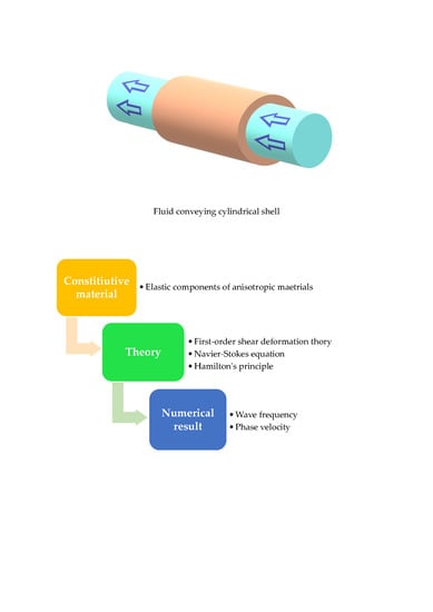
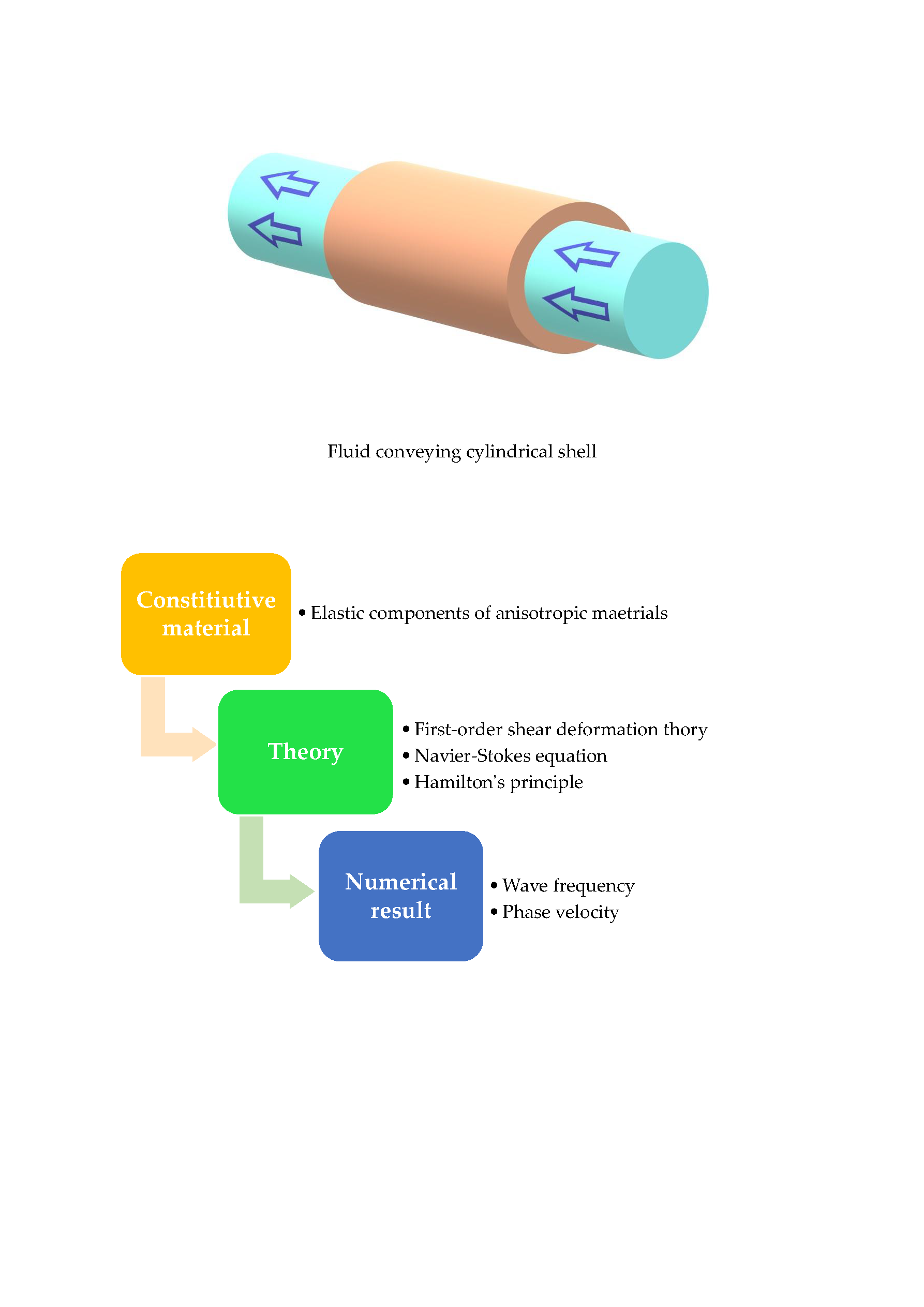
:In the present article, first-order shear deformation theory (FSDT) of the shell has been employed, for the first time, in order to analyze the propagation of the flexural waves in anisotropic fluid-conveying cylindrical shells. Four various anisotropic materials are utilized and their wave propagation behavior surveyed. Viscous fluid flow has been regarded to be laminar, fully developed, Newtonian, and axially symmetric. The Navier–Stokes equation can be utilized to explore the flow velocity effect. FSDT of the shell and Hamilton’s principle have been employed in order to achieve governing equations of anisotropic fluid-conveying cylindrical shells and finally, the obtained governing equations have been solved via an analytical method. In addition, the influences of different variables such as flow velocity, radius to thickness ratio, and longitudinal and circumferential wave numbers have been investigated and indicated within the framework of a detailed set of figures.
1. Introduction
Shell-type structural elements have been extensively utilized in various modern industries and engineering fields. Some of the typical instances of shell constructions which can be mentioned are pressure vessels, silos, automobile bodies, submarine hulks, ship hulls, and intersecting and branching pipelines. Owing to this, it is essential that the mechanical behavior of this type of structural element should be investigated, and many investigations have been conducted on the mechanical behavior of shells [1,2,3]. For example, Tornabene et al. [4] studied vibrational responses of thick and moderately-elliptic shells and cylinders made of laminated composite, utilizing the generalized differential quadrature method (GDQM). The free-vibration behavior of arbitrarily-shaped laminated composite doubly-curved shells on the basis of higher-order shear deformation theory (HSDT) using the GDQM and Non-uniform rational basis spline (NURBS)-based isogeometric approach was surveyed by Tornabene et al. [5]. Civalek [6] probed the rotation effect on the dynamic response of functionally-graded materials (FGMs) and laminated composite and isotropic, orthotropic truncated conical shells, circular shells, and panels. Wang and Wu [7] investigated vibrational responses of an FGM cylindrical shell considering the effects of porosity and different boundary conditions based on the sinusoidal shear deformation theory. Analysis of three-dimensional (3D) thermoelastic deformation of carbon nanotube (CNT)-reinforced nanocomposite cylindrical shells under the thermal environment was carried out by Pourasghar et al. [8] via GDQM. Nonlinear dynamic behavior of FGM moderately-thick toroidal shell lying on the Pasternak foundation through Reddy’s shell theory was analyzed by Vuong and Duc [9]. Moreover, Ghasemi et al. [10] employed the Kirchhoff–Love shell theory to examine aggregation influences on the dynamic behavior of multi-scale hybrid laminated cylindrical shells. FSDT of the shell was used by Ebrahimi et al. [11] to study free vibrational behaviors of porous metal foam cylindrical shells using Galerkin’s method. Porosity influence on nonlinear vibration characteristics of the composite sandwich doubly-curved shell within the framework of the HSDT was investigated by Karimiasl et al. [12]. The stability problem of a graphene oxide powder-reinforced nanocomposite shell resting on an elastic foundation based upon FSDT of the shell was solved by Ebrahimi et al. [13] utilizing Galerkin’s method. Recently, the dynamic stability of bi-dimensional FGM cylindrical shells with consideration of porosity and different boundary condition influences was surveyed by Allahkarami et al. [14].
Furthermore, analysis of the mechanical behavior of isotropic materials has been extensively performed. The structural complexity of anisotropic materials is more than that of isotopic materials. For example, 21 elastic constants can be defined for a fully-anisotropic material while two independent elastic constants can be defined for isotropic materials. Due to this, studying this topic can be useful in the design and analysis of structures with anisotropic materials. This topic has attracted scientists’ attention and several studies have been presented by them [15,16,17,18,19,20]. For example, Ferreira et al. [21] probed the natural frequency of thick monoclinic, orthotropic, and hexagonal plates according to FSDT and using a meshless method. The static and dynamic behavior of thin anisotropic plates based upon the boundary element method has been discussed by Paiva et al. [22]. Tornabene [23] analyzed free vibrational characteristics of anisotropic laminated composite doubly-curved shells within the framework of FSDT in conjunction with GDQM. Classical plate theory has been utilized by Singhal and Bindal [24] in order to solve the vibration problem of an embedded monoclinic rectangular plate. The nonlinear vibration response of anisotropic laminated cylindrical shells resting on the Pasternak medium within the framework of HSDT has been investigated by Shen [25]. Kumar [26] has explored the natural frequency characteristics of a monoclinic rectangular plate lying on Winkler substrate via a differential transform method. Vibration analysis of orthotropic pulse detonation engines subjected to moving pressures has been conducted by Mirzaei et al. [27]. Ahmadi and Rasheed [28] have examined lateral-torsional stability of thin anisotropic beams subjected to concentrated loading at mid-span/mid-height in the framework of the classical plate theory. DQM has been implemented by Bahrami et al. [29] to probe the bending behavior of monoclinic plates via 3D elasticity theory. Lately, Heyliger and Asiri [30] have studied nonlinear vibrational behavior of isotropic and anisotropic Euler–Bernoulli beams. Vibrational and elastic-plastic behavior of homogeneous and heterogeneous cylindrical tubes exposed to the internal moving pressure have been examined by Malekan et al. [31] using the finite element method.
Analysis of wave propagation in various structures like beam, plate, membrane, and shell, with various materials is one of the most fascinating issues in exploring mechanical behavior. Great efforts have been performed on this topic by researchers. For instance, wave dispersion analysis of the FGM Euler–Bernoulli beam in the thermal environment concerning the effect of impact force has been carried out by Akbaş [32]. Wave propagation characteristics of an FGM circular cylinder exposed to dynamic loadings have been presented by Dorduncu et al. [33]. Janghorban and Nami [34] have investigated the wave dispersion response of CNT-reinforced nanocomposite plates based on second-order shear deformation theory. Fourn et al. [35] have examined the wave propagation behavior of FGM plates utilizing a hyperbolic shear deformation theory. Propagation of waves in beams is the framework of various beam theories including Euler–Bernoulli (classic), Timoshenko, and Reddy beam theories which have been surveyed by Gul and Aydogdu [36]. Besides, Ebrahimi et al. [37] have analyzed the dispersion of waves in a symmetrically- and asymmetrically-porous nanocomposite cylindrical shells reinforced with graphene platelet according to FSDT. Bouanati et al. [38] have studied dynamic and wave propagation characteristics of triclinic and orthotropic plates based upon quasi-3D shear deformation theory. Lately, wave dispersion analysis of multi-scale hybrid nanocomposite circular cylindrical shells to determine the effect of CNT agglomeration on the basis of the FSDT has been performed by Ebrahimi and Seyfi [37]. Pursuant to the noted review of literature results, it is obvious that there is no investigation on wave propagation analysis of anisotropic fluid-conveying cylindrical shells which has not yet been published.
In the present research, the wave propagation behavior of anisotropic fluid-conveying cylindrical shells has been surveyed. Various anisotropic materials such as monoclinic, triclinic, trigonal, and hexagonal materials are covered in this paper. Motion equations of cylindrical shells were obtained by applying FSDT. Viscous fluid flow is supposed to be Newtonian, laminar, fully developed, and axially symmetric. Governing equations are solved analytically and circular frequency can be found. Finally, the influence of each parameter has been indicated in a group of diagrams that can be seen in future sections.
2. Anisotropic Materials
Hooke’s law usually denotes the material characteristics and relations of the unknown stresses and strains for isotropic and anisotropic materials. The stress–strain relationship generally can be expressed as follow:
where σij, Cijkl, and εkl denote components of Cauchy stress, elasticity, and strain tensors, respectively. The elastic components of four anisotropic materials, namely monoclinic, triclinic, trigonal, and hexagonal materials which are utilized in the present study are presented below.
A material with one plane of material symmetry or in other words having one symmetry plane is called monoclinic material. Moreover, monoclinic materials are reflected about z-axis. The elastic components of monoclinic materials which are used here can be defined as follows [17]:
The mass density of monoclinic materials is considered to be ρ = 2649 Kg/m3.
The matrix of elastic constants of triclinic materials can be calculated from that of a transversely-isotropic material by appropriate rotations about the x1- and the rotated x2-axis [39], where x1 and x2 refer to the x-axis and y-axis in the Cartesian coordinate. The elastic components of triclinic materials which are utilized here can be defined as follows [17]:
The mass density of triclinic materials is considered to be ρ = 7750 Kg/m3.
The hexagonal crystal family includes two crystal systems namely trigonal and hexagonal crystal systems. There are the 12-point groups for the hexagonal crystal family such that at least one of their space groups possesses the hexagonal lattice as underlying lattice and is the union of the hexagonal crystal system and the trigonal crystal system. The trigonal crystal system consists of the 5-point groups that have a single three-fold rotation axis, which includes space groups 143 to 167. The elastic components of trigonal materials which are utilized here can be defined as follows [17]:
The mass density of trigonal materials is considered to be ρ = 2649 Kg/m3.
The hexagonal crystal system consists of the 7-point groups that have a single six-fold rotation axis which includes space groups 168 to 194. Beryllium crystal is taken into account as a material with the hexagonal system. This material acts in such a way that a 60° rotation about its axis of symmetry causes the space lattice to return to the primitive point. The elastic components of hexagonal materials which are used here can be defined as follows [17]:
The mass density of hexagonal materials is considered to be ρ = 1850 Kg/m3.
3. First-Order Shear Deformation Shell Theory
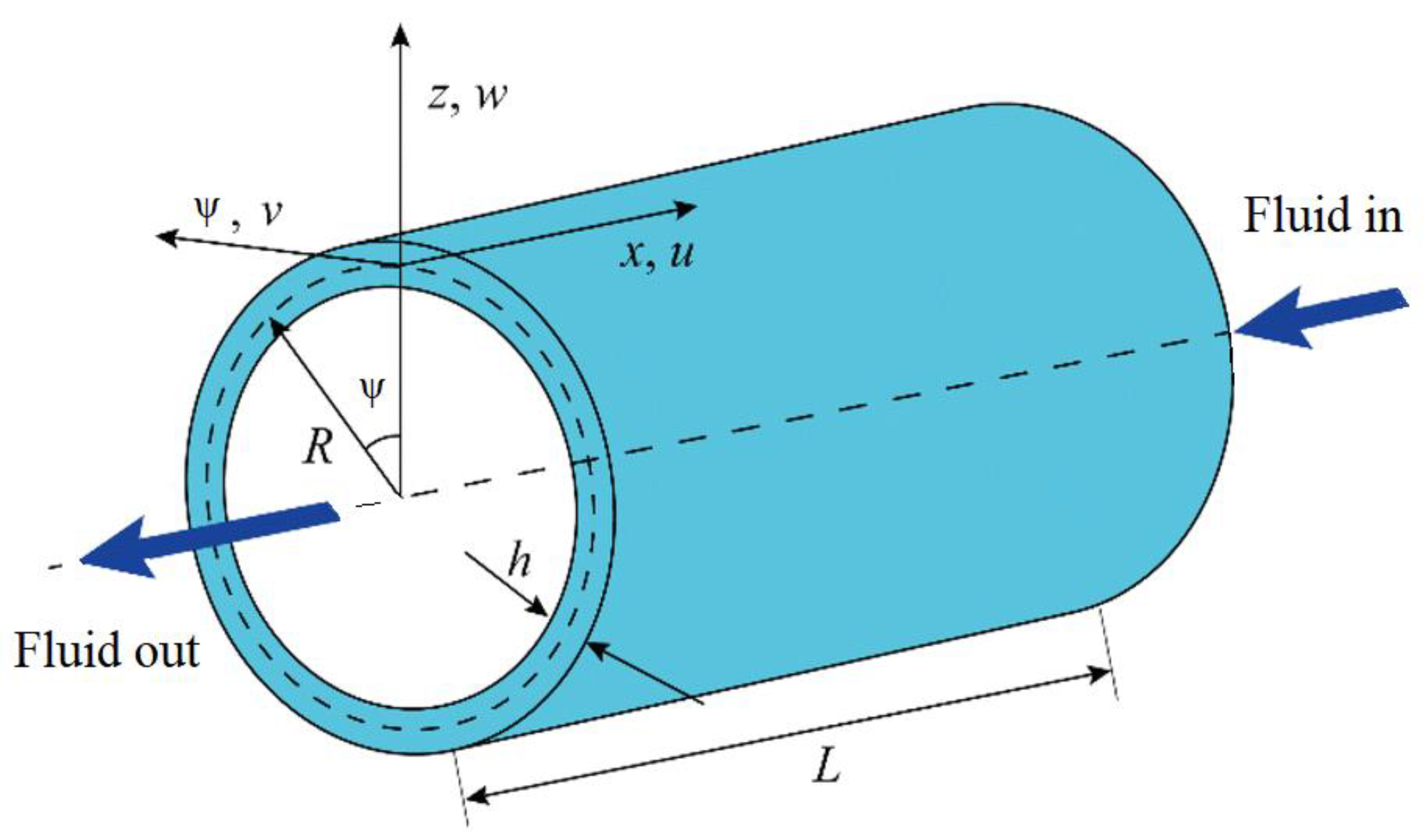
The schematic and coordinate system of the anisotropic cylindrical shell is observable in Figure 1. Based on FSDT, displacement fields at every point of the anisotropic cylindrical shell can be introduced as follows [40]:
where u, v, w, θx, and θψ denote axial, circumferential, and lateral displacements and the rotation elements about axial and circumferential directions, respectively, and t denotes time. Therefore, the nonzero strains of a cylindrical shell can be written in the following form [40]:
Now, to reach Euler–Lagrange relations of anisotropic cylindrical shells, the Hamiltonian approach is employed and can be stated as:
in which ΠS, ΠK, and ΠW represent strain energy, kinetic energy, and work done by an external force, respectively. The variation of strain energy for an elastic solid can be written as follows:
The variation of kinetic energy can be presented as follows:
The viscous fluid flow in anisotropic cylindrical shells is supposed to be an axially symmetric, fully developed, laminar, and Newtonian [41]. Thus, the Navier–Stokes equation can be applied. The momentum equation of the fluid flow can be expressed as follows:
where ρf and P stand for density and pressure of the fluid, respectively. Owing to the mutual identity between the acceleration and speed of the fluid and cylindrical shell in the contact points, the following relations can be extended as follows:
where vx denotes the mean flow velocity. Shear stress (τ) and viscosity (μf) relations can be written in the following form:
In the present work, ρf and μf are taken 1100 Kg/m3 and 0.25 cP.
The variation of work done by external loadings can be formulated as follows:
in which Nr, Nx, and Nψ are radial, axial, and circumferential loadings, respectively, which have not been regarded. Therefore, to attain the motion equations of cylindrical shell, Equations (11), (12), and (16) are inserted into Equation (10) and the obtained equations can be stated as follows:
where
here κs denotes shear correction factor.
Integrating from the above equation over the shell thickness, the following relation can be obtained:
in which
Ultimately, by coupling Equations (17)–(21) with Equation (25), the governing equations of anisotropic cylindrical shells can be obtained such as below:
An analytical solution method has been applied to solve the obtained governing equations of anisotropic cylindrical shells. Therefore, the displacement fields are supposed to be as:
where U, V, and W are the displacement amplitudes and Θx and Θψ are the rotation amplitudes. Moreover, βx and βn represent longitudinal and circumferential wave numbers, respectively, and ωn is circular frequency. By substituting u, v, w, θx, and θψ from Equation (33) in Equations (28)–(32), the following equation is obtained:
where components of these matrices are:
In order to solve this eigenvalue problem, the determinant of the coefficient matrix of Equation (34) must be set to zero:
Furthermore, by setting , the phase velocity can be obtained via
4. Numerical Results
In this section, a group of numerical results is illustrated to show the effects of different parameters on the variation of wave frequency and phase velocity of anisotropic cylindrical shells. The length and radius of the cylindrical shell are considered to be 25 times greater than the thickness of the shell and the cylindrical shell thickness is regarded to be 0.03 m in all of the diagrams. Firstly, the introduced methodology has been verified by comparing the presented results with those reported by Ke et al. [42] and Barati and Zenkour [43]. According to Table 1, there is a good consistency between the outcomes of our modeling and those reported in the former references.
Shear deformation and rotary inertia are neglected in classical shell theories and because of this, the response of these theories is not accurate. In order to overcome this weakness and limitation, shear deformation theories (i.e., FSDT and HSDT) are introduced. In FSDT, a uniform shear strain is presumed along with the thickness of the shell and also a shear correction factor is needed for the equilibrium. The limitations of classical theories have been modified to a certain extent by FSDT because shear stress distribution along the thickness of the shell may not be presumed correctly in FSDT. HSDT can completely overcome the limitation of classical shell theories.
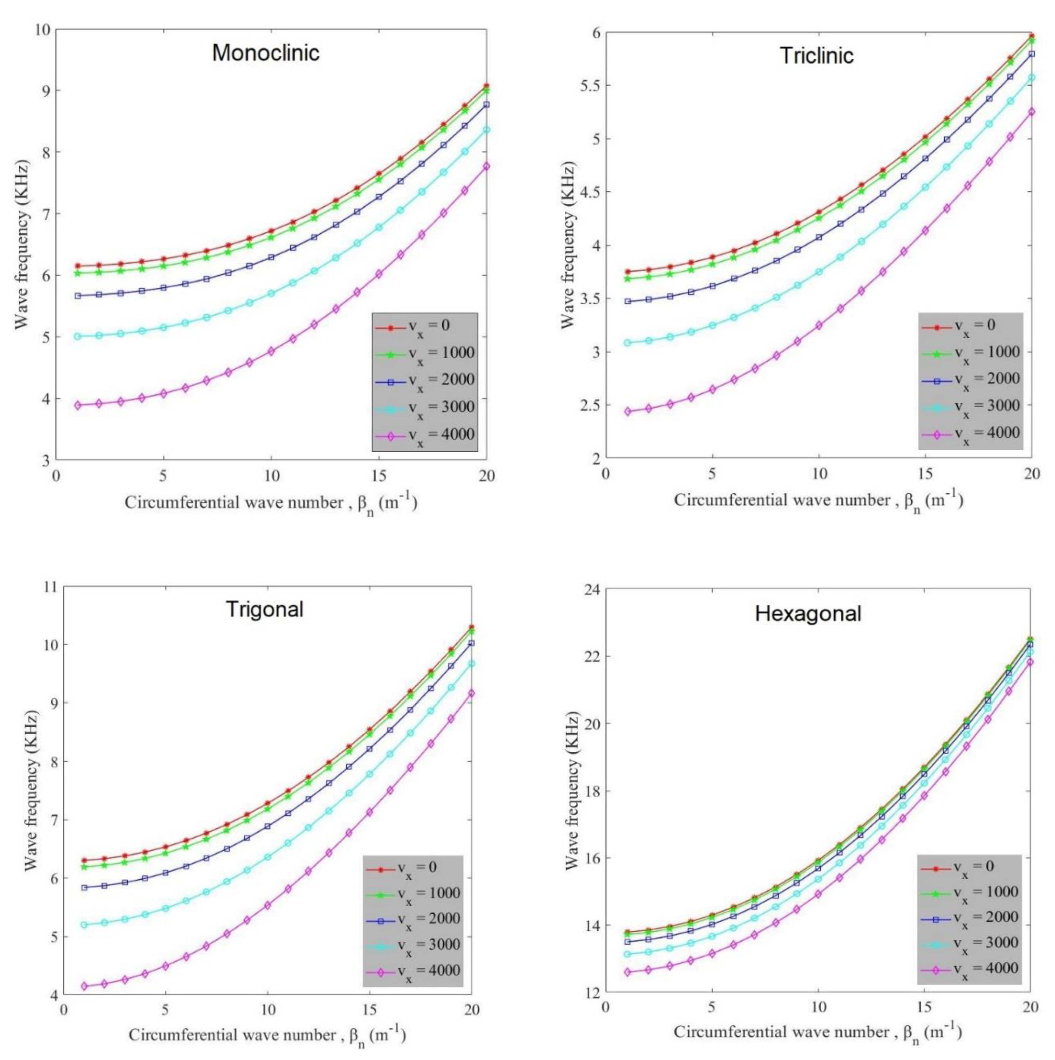
Figure 2 explores the effect of flow velocity on the variation of wave frequency of anisotropic cylindrical shells against the circumferential wave number. As observed, at a constant longitudinal wave number, with increasing circumferential wave number, wave frequency increases in every anisotropic cylindrical shell. There is a damping effect due to the existence of fluid flow in the cylindrical shell. Hence, flow velocity has a decreasing influence on the value of wave frequency in such a way that wave frequency is lessened with an increase of flow velocity amount. Flow velocity affects wave frequency values of hexagonal materials less than other ones. The diagrams have a similar trend but there is a difference in the value of wave frequency of these diagrams. Hexagonal, trigonal, monoclinic, and triclinic materials experience the greatest value of wave frequency, respectively. This behavior is because the hexagonal crystal system of anisotropic materials possesses greater stiffness in comparison with the crystal systems of other materials.
Figure 3 indicates the variation of wave frequency of anisotropic cylindrical shells against circumferential wave number for different radius to thickness ratios (R/h). Based on the graphs, it can be seen that at a constant flow velocity, radius to thickness ratio plays a decreasing role in the variation of wave frequency values. This behavior is because the increment of radius to thickness ratio makes the structure weaker and hence higher values of wave frequency occur with lower radius to thickness ratios. Similarly to Figure 2, hexagonal and triclinic materials have the highest and lowest wave frequency values, respectively. Also, wave frequency value increases with increase in circumferential wave number.
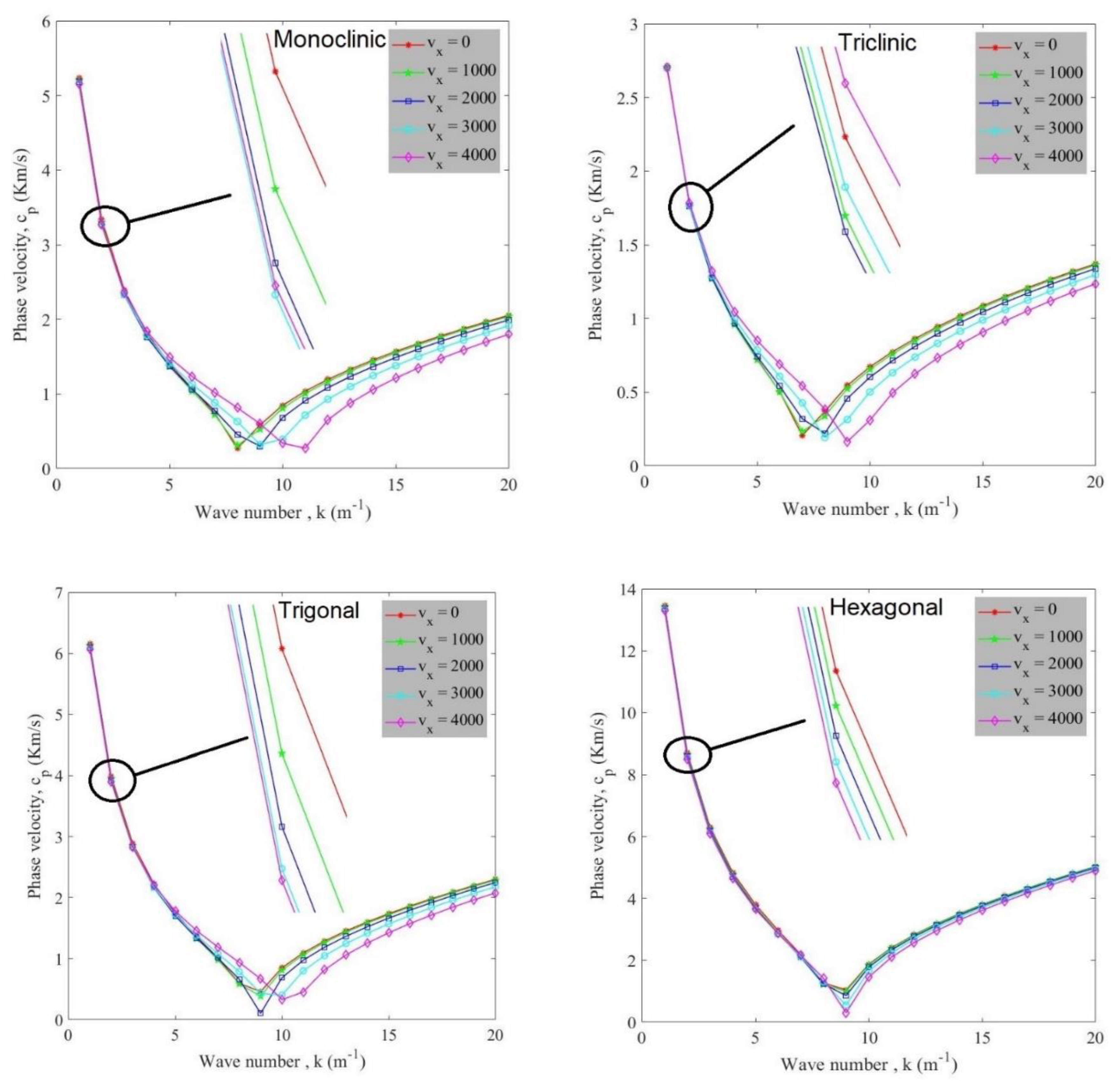
Variation of phase velocity of anisotropic cylindrical shells against wave number for different flow velocities is demonstrated in Figure 4. It can be observed that by increasing the number of waves, phase velocity is initially reduced to its minimum value and it then increases. The minimum points of each curve represent the critical wave number for the corresponding flow velocity. In other words, critical flow velocity, in which a structure losses its stability, happens at a certain wave number. For example, in triclinic shell, k = 7 is related to vx = 0 and vx = 1000, k = 8 is related to vx = 2000 and vx = 3000, and k = 9 is related to vx = 4000; in monoclinic shell, k = 8 is related to vx = 0 and vx = 1000, k = 9 is related to vx = 2000 and vx = 3000, and k = 11 is related to vx = 4000; and in trigonal shell, k = 9 is related to vx = 0, vx = 1000 and vx = 2000 and k = 10 is related to vx = 3000 and vx = 4000; and finally, in hexagonal shell, k = 9 is related to all of the flow velocities. Besides, flow velocity possesses a negative effect on the variation of phase velocity values and this negative effect is owing to the aforementioned damping influence.
The influence of radius to thickness ratio on the variation of phase velocity of anisotropic cylindrical shells against wave number is studied in Figure 5. It is observable that higher phase velocity can occur by selecting a lower amount of radius to thickness ratio. On the other hand, as mentioned before, the increment of radius to thickness ratio affects the value of phase velocity decreasingly. Phase velocity firstly is decreased and then increases with the growth of wave number amount. These diagrams are plotted at vx = 2000 and based upon these diagrams it can be expressed that at a certain flow velocity, by varying radius to thickness ratio, critical wave number changes. For more explanation, it can be said that critical flow velocity can happen at various wave number and it depends on the amount of radius to thickness ratio. Also, as same as other illustrations, triclinic, monoclinic, trigonal and hexagonal possess the lowest value of phase velocity, respectively.
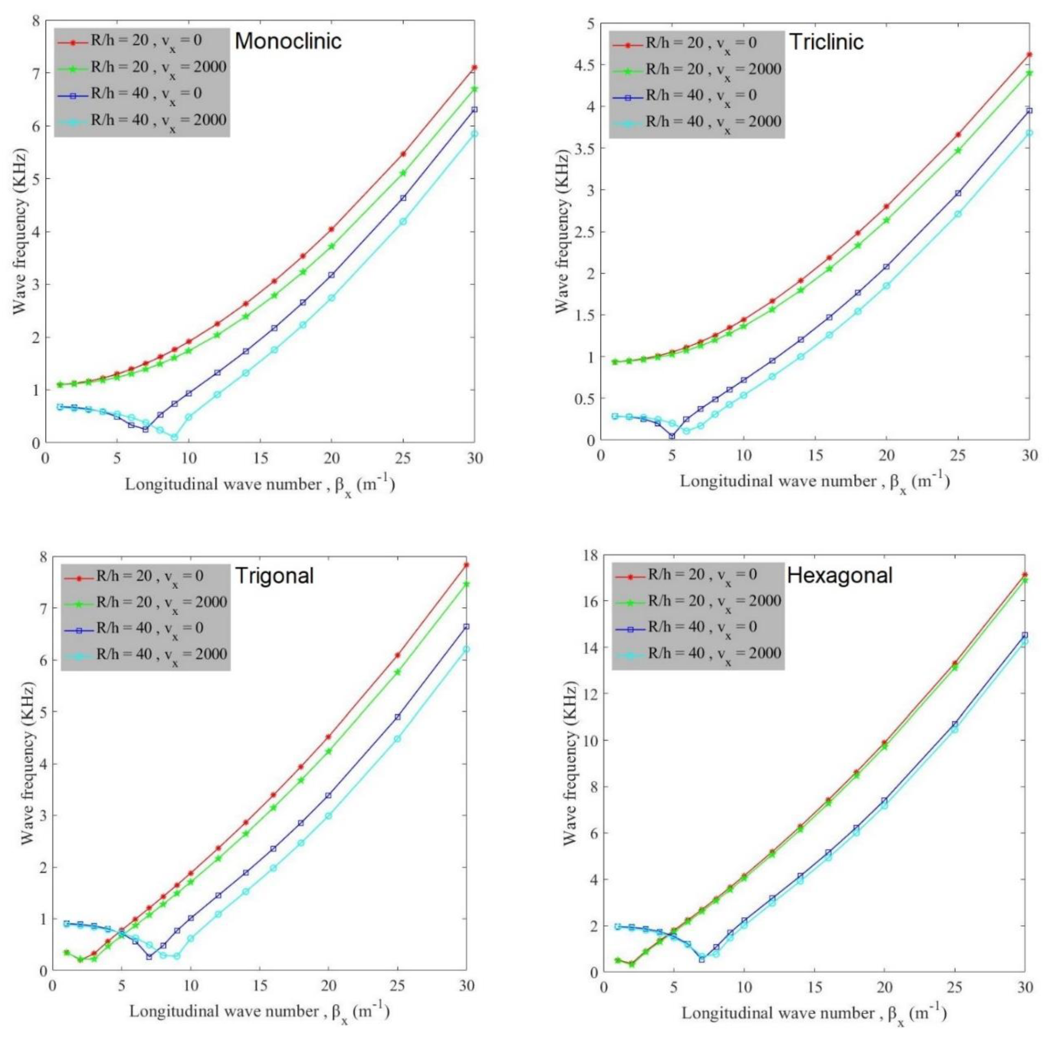
Eventually, Figure 6 reveals how flow velocity affects the variation of wave frequency of anisotropic cylindrical shells against longitudinal wave number for different radius to thickness ratios. It is obvious that the shells with lower radius to thickness ratio can tolerate higher wave frequency compared to shells with greater radius to thickness ratio. Moreover, at a constant radius to thickness ratio, wave frequency values are lessened when the amount of flow velocity grows. The choosing shells with lower radius to thickness ratio and flow velocity can be a proper choice. In addition, with an increasing longitudinal wave number, wave frequency is gradually reduced to its minimum value and after that increases.
5. Conclusions
Flexural wave propagation characteristics of anisotropic fluid-conveying cylindrical shells are studied in this research, based upon FSDT of the shell. Four anisotropic materials; namely monoclinic, triclinic, trigonal, and hexagonal were used in the present research. Moreover, the FSDT of shell and Hamilton’s principle were exerted to obtain the kinetic relations. Here, the most important concluding remarks will be reviewed as:
- Wave frequency and phase velocity of anisotropic cylindrical shells can be reduced by increasing flow velocity amount;
- There is a critical flow velocity that occurs for cylindrical shells at various wave numbers and it can be different for various radius to thickness ratios and different anisotropic materials;
- Hexagonal, trigonal, monoclinic, and triclinic materials experience the highest wave frequency, respectively;
- With an increase in radius to thickness ratio there is a decreasing effect on the value of wave frequency and phase velocity of anisotropic fluid-conveying cylindrical shells.
Our future works include:
- Conducting wave propagation analysis of anisotropic fluid-conveying truncated conical shell;
- Performing wave propagation analysis of anisotropic joined conical–conical shells;
- Analyzing the wave propagation behavior of anisotropic joined conical–cylindrical–conical shells.
Author Contributions
Conceptualization, F.E. and A.S.; methodology, F.E. and A.S.; software, F.E. and A.S.; validation, F.E. and A.S.; formal analysis, F.E. and A.S.; investigation, F.E. and A.S.; resources, X.X.; data curation, X.X.; writing—original draft preparation, F.E. and A.S.; writing—review and editing, F.E. and A.S. All authors have read and agreed to the published version of the manuscript.
Funding
This investigation received no specific grant from any funding agency in the public, commercial, or not-for-profit sectors.
Conflicts of Interest
The authors declare that there are no conflicts of interest regarding the publication of this paper.
References
- Sheng, G.; Wang, X. Thermomechanical vibration analysis of a functionally graded shell with flowing fluid. Eur. J. Mech. A Solids 2008, 27, 1075–1087. [Google Scholar] [CrossRef]
- Bagherizadeh, E.; Kiani, Y.; Eslami, M. Thermal buckling of functionally graded material cylindrical shells on elastic foundation. AIAA J. 2012, 50, 500–503. [Google Scholar] [CrossRef]
- Sofiyev, A.; Kuruoglu, N. Torsional vibration and buckling of the cylindrical shell with functionally graded coatings surrounded by an elastic medium. Compos. Part B Eng. 2013, 45, 1133–1142. [Google Scholar] [CrossRef]
- Tornabene, F.; Fantuzzi, N.; Bacciocchi, M.; Dimitri, R. Dynamic analysis of thick and thin elliptic shell structures made of laminated composite materials. Compos. Struct. 2015, 133, 278–299. [Google Scholar] [CrossRef]
- Tornabene, F.; Fantuzzi, N.; Bacciocchi, M. The GDQ method for the free vibration analysis of arbitrarily shaped laminated composite shells using a NURBS-based isogeometric approach. Compos. Struct. 2016, 154, 190–218. [Google Scholar] [CrossRef]
- Civalek, Ö. Discrete singular convolution method for the free vibration analysis of rotating shells with different material properties. Compos. Struct. 2017, 160, 267–279. [Google Scholar] [CrossRef]
- Wang, Y.; Wu, D. Free vibration of functionally graded porous cylindrical shell using a sinusoidal shear deformation theory. Aerosp. Sci. Technol. 2017, 66, 83–91. [Google Scholar] [CrossRef]
- Pourasghar, A.; Moradi-Dastjerdi, R.; Yas, M.; Ghorbanpour Arani, A.; Kamarian, S. Three-dimensional analysis of carbon nanotube-reinforced cylindrical shells with temperature-dependent properties under thermal environment. Polym. Compos. 2018, 39, 1161–1171. [Google Scholar] [CrossRef]
- Vuong, P.M.; Duc, N.D. Nonlinear vibration of FGM moderately thick toroidal shell segment within the framework of Reddy’s third order-shear deformation shell theory. Int. J. Mech. Mater. Des. 2019, 16, 1–20. [Google Scholar] [CrossRef]
- Ghasemi, A.R.; Mohandes, M.; Dimitri, R.; Tornabene, F. Agglomeration effects on the vibrations of CNTs/fiber/polymer/metal hybrid laminates cylindrical shell. Compos. Part B Eng. 2019, 167, 700–716. [Google Scholar] [CrossRef]
- Ebrahimi, F.; Dabbagh, A.; Rastgoo, A. Vibration analysis of porous metal foam shells rested on an elastic substrate. J. Strain Anal. Eng. Des. 2019, 54, 199–208. [Google Scholar] [CrossRef]
- Karimiasl, M.; Ebrahimi, F.; Mahesh, V. Nonlinear forced vibration of smart multiscale sandwich composite doubly curved porous shell. Thin Walled Struct. 2019, 143, 106152. [Google Scholar] [CrossRef]
- Ebrahimi, F.; Hafezi, P.; Dabbagh, A. Buckling analysis of embedded graphene oxide powder-reinforced nanocomposite shells. Available online: https://doi.org/10.1016/j.dt.2020.02.010 (accessed on 2 January 2020).
- Allahkarami, F.; Tohidi, H.; Dimitri, R.; Tornabene, F. Dynamic Stability of Bi-Directional Functionally Graded Porous Cylindrical Shells Embedded in an Elastic Foundation. Appl. Sci. 2020, 10, 1345. [Google Scholar] [CrossRef] [Green Version]
- Kögl, M. Free vibration analysis of anisotropic solids with the boundary element method. Eng. Anal. Bound. Elem. 2003, 27, 107–114. [Google Scholar] [CrossRef]
- Towfighi, S.; Kundu, T. Elastic wave propagation in anisotropic spherical curved plates. Int. J. Solids Struct. 2003, 40, 5495–5510. [Google Scholar] [CrossRef]
- Batra, R.; Qian, L.; Chen, L. Natural frequencies of thick square plates made of orthotropic, trigonal, monoclinic, hexagonal and triclinic materials. J. Sound Vib. 2004, 270, 1074–1086. [Google Scholar] [CrossRef]
- Demasi, L. Quasi-3D analysis of free vibration of anisotropic plates. Compos. Struct. 2006, 74, 449–457. [Google Scholar] [CrossRef]
- Lü, C.; Huang, Z.; Chen, W. Semi-analytical solutions for free vibration of anisotropic laminated plates in cylindrical bending. J. Sound Vib. 2007, 304, 987–995. [Google Scholar] [CrossRef]
- Jansen, E. The effect of geometric imperfections on the vibrations of anisotropic cylindrical shells. Thin Walled Struct. 2007, 45, 274–282. [Google Scholar] [CrossRef]
- Ferreira, A.; Fasshauer, G.; Batra, R. Natural frequencies of thick plates made of orthotropic, monoclinic, and hexagonal materials by a meshless method. J. Sound Vib. 2009, 319, 984–992. [Google Scholar] [CrossRef]
- Paiva, W.P.; Sollero, P.; Albuquerque, E.L. Modal analysis of anisotropic plates using the boundary element method. Eng. Anal. Bound. Elem. 2011, 35, 1248–1255. [Google Scholar] [CrossRef]
- Tornabene, F. 2-D GDQ solution for free vibrations of anisotropic doubly-curved shells and panels of revolution. Compos. Struct. 2011, 93, 1854–1876. [Google Scholar] [CrossRef]
- Singhal, P.; Bindal, G. Generalised differential quadrature method in the study of free vibration analysis of monoclinic rectangular plates. Am. J. Comput. Appl. Math. 2012, 2, 166–173. [Google Scholar] [CrossRef]
- Shen, H.-S. Boundary layer theory for the nonlinear vibration of anisotropic laminated cylindrical shells. Compos. Struct. 2013, 97, 338–352. [Google Scholar] [CrossRef]
- Kumar, Y. Differential transform method to study free transverse vibration of monoclinic rectangular plates resting on Winkler foundation. Appl. Comput. Mech. 2013, 7, 145–154. [Google Scholar]
- Mirzaei, M.; Asadi, M.T.; Akbari, R. On vibrational behavior of pulse detonation engine tubes. Aerosp. Sci. Technol. 2015, 47, 177–190. [Google Scholar] [CrossRef]
- Ahmadi, H.; Rasheed, H.A. Lateral torsional buckling of anisotropic laminated thin-walled simply supported beams subjected to mid-span concentrated load. Compos. Struct. 2018, 185, 348–361. [Google Scholar] [CrossRef]
- Bahrami, K.; Afsari, A.; Janghorban, M.; Karami, B. Static analysis of monoclinic plates via a three-dimensional model using differential quadrature method. Struct. Eng. Mech. 2019, 72, 131–139. [Google Scholar]
- Heyliger, P.R.; Asiri, A. A total Lagrangian elasticity formulation for the nonlinear free vibration of anisotropic beams. Int. J. Non Linear Mech. 2020, 118, 103286. [Google Scholar] [CrossRef]
- Malekan, M.; Khosravi, A.; Zanin, A.; Aghababaei, R. On the vibrational responses of thin FGM tubes subjected to internal sequential moving pressure. J. Braz. Soc. Mech. Sci. Eng. 2020, 42, 220. [Google Scholar] [CrossRef]
- Akbaş, Ş.D. Wave propagation of a functionally graded beam in thermal environments. Steel Compos. Struct. 2015, 19, 1421–1447. [Google Scholar] [CrossRef]
- Dorduncu, M.; Apalak, M.K.; Cherukuri, H. Elastic wave propagation in functionally graded circular cylinders. Compos. Part B Eng. 2015, 73, 35–48. [Google Scholar] [CrossRef]
- Janghorban, M.; Nami, M.R. Wave propagation in functionally graded nanocomposites reinforced with carbon nanotubes based on second-order shear deformation theory. Mech. Adv. Mater. Struct. 2017, 24, 458–468. [Google Scholar] [CrossRef]
- Fourn, H.; Atmane, H.A.; Bourada, M.; Bousahla, A.A.; Tounsi, A.; Mahmoud, S. A novel four variable refined plate theory for wave propagation in functionally graded material plates. Steel Compos. Struct. 2018, 27, 109–122. [Google Scholar]
- Gul, U.; Aydogdu, M. Wave propagation analysis in beams using shear deformable beam theories considering second spectrum. J. Mech. 2018, 34, 279–289. [Google Scholar] [CrossRef]
- Ebrahimi, F.; Seyfi, A.; Dabbagh, A.; Tornabene, F. Wave dispersion characteristics of porous graphene platelet-reinforced composite shells. Struct. Eng. Mech. 2019, 71, 99–107. [Google Scholar]
- Bouanati, S.; Benrahou, K.H.; Atmane, H.A.; Yahia, S.A.; Bernard, F.; Tounsi, A.; Bedia, E.A.A. Investigation of wave propagation in anisotropic plates via quasi 3D HSDT. Geomech. Eng. 2019, 18, 85–96. [Google Scholar]
- Dravinski, M.; Niu, Y. Three-dimensional time-harmonic Green’s functions for a triclinic full-space using a symbolic computation system. Int. J. Numer. Methods Eng. 2002, 53, 445–472. [Google Scholar] [CrossRef]
- Ebrahimi, F.; Seyfi, A. Wave propagation response of multi-scale hybrid nanocomposite shell by considering aggregation effect of CNTs. Mech. Based Des. Struct. Mach. 2019, 47, 1–22. [Google Scholar] [CrossRef]
- Rabani Bidgoli, M.; Saeed Karimi, M.; Ghorbanpour Arani, A. Nonlinear vibration and instability analysis of functionally graded CNT-reinforced cylindrical shells conveying viscous fluid resting on orthotropic Pasternak medium. Mech. Adv. Mater. Struct. 2016, 23, 819–831. [Google Scholar] [CrossRef]
- Ke, L.; Wang, Y.; Reddy, J. Thermo-electro-mechanical vibration of size-dependent piezoelectric cylindrical nanoshells under various boundary conditions. Compos. Struct. 2014, 116, 626–636. [Google Scholar] [CrossRef]
- Barati, M.R.; Zenkour, A.M. Vibration analysis of functionally graded graphene platelet reinforced cylindrical shells with different porosity distributions. Mech. Adv. Mater. Struct. 2019, 26, 1580–1588. [Google Scholar] [CrossRef]
Figure 1.
Schematic and coordinates of an anisotropic fluid-conveying cylindrical shell.

Figure 2.
Variation of wave frequency against circumferential wave number for various flow velocities for different anisotropic materials.
Figure 2.
Variation of wave frequency against circumferential wave number for various flow velocities for different anisotropic materials.

Figure 3.
Variation of wave frequency against circumferential wave number for various radius to thickness ratios for different anisotropic materials (vx = 2000).
Figure 3.
Variation of wave frequency against circumferential wave number for various radius to thickness ratios for different anisotropic materials (vx = 2000).

Figure 4.
Variation of phase velocity against wave number for various flow velocities for different anisotropic materials.
Figure 4.
Variation of phase velocity against wave number for various flow velocities for different anisotropic materials.

Figure 5.
Variation of phase velocity against wave number for various radius to thickness ratios for different anisotropic materials (vx = 2000).
Figure 5.
Variation of phase velocity against wave number for various radius to thickness ratios for different anisotropic materials (vx = 2000).

Figure 6.
Variation of wave frequency against longitudinal wave number for various flow velocities and radius to thickness ratios for different anisotropic materials (βn = 10).
Figure 6.
Variation of wave frequency against longitudinal wave number for various flow velocities and radius to thickness ratios for different anisotropic materials (βn = 10).


Table 1.
Comparison of dimensionless natural frequencies of cylindrical shells for both S–S and C–C boundary conditions ().
Table 1.
Comparison of dimensionless natural frequencies of cylindrical shells for both S–S and C–C boundary conditions ().
| Boundary conditions | n | ||||||||
|---|---|---|---|---|---|---|---|---|---|
| 1 | Error (%) | 2 | Error (%) | 3 | Error (%) | 4 | Error (%) | ||
| S–S | [42] | 0.01608 | 0.124 | 0.00938 | 0 | 0.02210 | 0.136 | 0.04209 | 0.285 |
| [43] | 0.01610 | 0 | 0.00938 | 0 | 0.02210 | 0.136 | 0.04208 | 0.261 | |
| Present | 0.01610 | 0.00938 | 0.02207 | 0.04197 | |||||
| C–C | [42] | 0.03276 | 7.173 | 0.01389 | 3.960 | 0.02267 | 0.176 | 0.04221 | 0.261 |
| [43] | 0.03278 | 7.108 | 0.01390 | 3.885 | 0.02267 | 0.176 | 0.04221 | 0.261 | |
| Present | 0.03511 | 0.01444 | 0.02271 | 0.04210 | |||||
© 2020 by the authors. Licensee MDPI, Basel, Switzerland. This article is an open access article distributed under the terms and conditions of the Creative Commons Attribution (CC BY) license (http://creativecommons.org/licenses/by/4.0/).
Share and Cite
MDPI and ACS Style
Ebrahimi, F.; Seyfi, A. Propagation of Flexural Waves in Anisotropic Fluid-Conveying Cylindrical Shells. Symmetry 2020, 12, 901. https://doi.org/10.3390/sym12060901
AMA Style
Ebrahimi F, Seyfi A. Propagation of Flexural Waves in Anisotropic Fluid-Conveying Cylindrical Shells. Symmetry. 2020; 12(6):901. https://doi.org/10.3390/sym12060901
Chicago/Turabian StyleEbrahimi, Farzad, and Ali Seyfi. 2020. "Propagation of Flexural Waves in Anisotropic Fluid-Conveying Cylindrical Shells" Symmetry 12, no. 6: 901. https://doi.org/10.3390/sym12060901
Note that from the first issue of 2016, this journal uses article numbers instead of page numbers. See further details here.