The Design and Implementation of a Sensorless Power Tool Based on a Microcontroller


1
Department of Electrical Engineering, College of Information and Electrical Engineering, Feng Chia University, 100 Wen Hwa Road, Taichung 40724, Taiwan
2
Ph.D. Program of Electrical and Communications Engineering, Feng Chia University, 100 Wen Hwa Road, Taichung 40724, Taiwan
*
Authors to whom correspondence should be addressed.
Electronics 2020, 9(6), 921; https://doi.org/10.3390/electronics9060921
Submission received: 28 April 2020
/
Revised: 26 May 2020
/
Accepted: 29 May 2020
/
Published: 1 June 2020
(This article belongs to the Special Issue Intelligent Electronic Devices)
Abstract
:Power tools are basic working tools used for production and manufacturing in the machinery and mechanical industries. The motor drive plays an important role in power tool applications. The performance of the motor drive will then directly or indirectly affect the quality and precision of the processing metal components. Most of the traditional motor drive control of a brushless direct current (BLDC) motor employs the Hall-effect position sensors to detect the rotor position. However, the installing sensors are prone to degrading the performance due to variations in temperature and the harsh environment. This disadvantage can be overcome with sensorless solutions. Among these sensorless solutions, the zero-crossing point detection of the back electromotive force (BEMF) is popular. Nevertheless, for the 180-degree conduction mode, it is impossible to directly detect the BEMF because of the three terminals of the motor which are conducted at any time for an electrical cycle. Therefore, a novel sensorless circuit approach based on the terminal line to line voltage is proposed in this paper. Moreover, an improved circuit scheme with a Schmitt trigger for sensing the BEMF is also proposed and implemented to obtain the precisely resembling Hall-effect signals. Finally, a prototype of a sensorless BLDC motor drive with a 180-degree conduction mode speed control for power tools is designed and implemented in this paper. The experimental results show that the proposed circuit works properly and validates the feasibility and fidelity of the motor drive system.
1. Introduction
In recent years, power tools, also known as electric hand tools, have been applied in many areas of the machinery and mechanical industries. Due to their convenience and easy operation, they have been widely employed in automotive maintenance, construction and home repair as well as in plant and garden pruning. The global power tools market is expected to increase at a compound annual growth rate of 5.5% and to reach US$41.7 billion during the period of time from 2019 to 2024 [1]. Therefore, technical performance and convenient operation in power tool design are becoming more and more essential, including factors such as smaller size, more robust operation, higher battery voltage driving capability and higher speed capability. In addition, power tools are required for the capability of forward and reverse rotation as well as operating at different speeds.
Brushed direct-current (DC) motors have been employed for such applications because of their excellent torque-speed characteristics and ease of control. However, when employing brushed DC motors to control current, a mechanical system known as the commutator brushes system is required. This means that the brushed DC motor has a short operating life because the brushes need more frequent maintenance and replacement over time. These disadvantages can be overcome by the use of brushless motors such as switched reluctance motors (SRMs) and BLDC motors. Surprisingly, the BLDC motor has torque-speed characteristics that are almost the same as those of brushed DC motors. Moreover, the BLDC motor has a higher efficiency and smaller size than the brushed DC motor [2,3], whereas SRMs are similar to brushless motor types. The motor does not employ any permanent magnets and its rotor contains only iron. Therefore, it has a low manufacturing cost as well as ruggedness [4,5] and can be operated at extremely high speeds [5]. Its torque-speed characteristics can be more easily adapted to the application’s requirements compared to permanent magnet motors [5]. However, because there is no permanent magnet mounted on its rotor, this means a magnetic field is produced only based on stator windings, resulting in the copper losses increasing [4,5]. Although SRMs can make it easy to achieve smooth torque at low speeds, they have the biggest disadvantage of ripple torque in their wide operating speed range that causes a large ripple current in the DC supply [5]. Moreover, considering its small size and its power density, the performance of the BLDC motor is higher than that of the SRM motor [5].
Consequently, in the last few decades, there has been interest in BLDC motors and they have been applied in many apparatuses and automotive repair and maintenance because of their outstanding features [2,3,6,7,8]. However, a BLDC motor, with its trapezoidal back electromotive force (BEMF) waveform, typically requires Hall-effect position sensors to identify the rotor position for the inverter switching operation. This leads to increases in cost and reduces its reliability, because Hall sensors are sensitive to temperature variations and harsh environments and precision is required for the sensor installation [9]. In addition, the absence of the position sensors may save space for applications in which its volume is limited. To solve these problems, in the last three decades, many sensorless motor drive solutions for BLDC motors have been proposed by many studies, and this is adequately surveyed in [10]. The methods can be classified as: (1) direct detection of the BEMF from the floating phase, (2) BEMF integration method, (3) detection method of freewheeling diode conduction, (4) detection of the stator third harmonic voltage components, and (5) detection method of average terminal voltage measurement [9,10,11,12,13,14]. Hence, the sensorless position control becomes a significant issue for BLDC motor drives [8,11]. Generally, two requirements need to be satisfied for a high-speed sensorless motor drive: generation of the sensorless commutation signals (SCSs) and reduction of the commutation errors between actual commutation signals and ideal commutation signals, which must be as small as possible [10]. In [11], the sensorless algorithm for commutation signals based on the line to line (L2L) BEMF is shown, which is calculated from the mathematical model of the BLDC motor. Zero-crossing points (ZCP) are derived by a fraction between two suitable L2L BEMFs and solved by code in firmware. Furthermore, in [15], instead of detecting the ZCP of the motor’s BEMF from the suspended phase, the estimated commutation signals are directly taken from the proper average L2L voltages by comparing the two-phase terminal voltage of a BLDC motor and passing it through the low-pass filters (LPF) and the comparators to generate the required commutation output signals. Accordingly, the commutation signals would appear to meet the ZCP of the average L2L voltages. These L2L ZCPs lag by 30 electrical degrees compared to the BEMF phase. The advantages of this technique are as follows: no virtual motor neutral voltage required, common-mode noise reduction and no need to have the phase shift circuit which may cause the circuit complexity. However, for a high-speed BLDC motor, the commutation signals might have a large delay which may be more than 90 electrical degrees in a widespread speed range [10]. Moreover, for the 180-degree conduction mode, the SCSs obtained from this technique are improper because the average L2L voltages received from the inverter are different from those of the 120-degree conduction mode. Therefore, a novel sensorless circuit is proposed in this paper for the 180-degree conduction mode. Furthermore, in order to improve the speed of both transition edges of SCSs and to reduce noise suppression and increase the stability of the motor drive system, a novel circuit scheme with a Schmitt trigger is employed in this paper for both of the conduction modes.
The above discussion of the sensorless BLDC motor drive solutions is essentially based on six-step interval switching. This involves a three-phase Y-connected BLDC motor being applied for both conduction modes. That is, for a 120-degree conduction mode, two phases are always switched on and the remainder phase suspended, and each phase is energized for two commutation cycles. Consequently, there is no torque produced in that suspended phase. In contrast, for a 180-degree conduction mode, each phase is commutated at any time for an electrical cycle. Its capability of delivering power from the inverter side to the motor side is larger than that of the 120-conduction scheme with a power supply of the same voltage [16]. In addition, in this 180-degree conduction system, the maximum torque produced is greater than that of the 120-degree conduction technique, up to 33% [16,17,18]. Furthermore, this control scheme has not been adequately investigated because of its complicated nature in comparison to the 120-degree control scheme [19]. That is, in the 180-degree mode, during the switching-on states, the high-side and the low-side power transistors overlap for a brief period, and this is known as cross conduction. This leads to a potential short circuit across the positive and ground terminals of the power supply [20]. To solve this severe problem, the solution of combining hardware design and a soft-chopping mode based on the pulse width modulation (PWM) control algorithm for a power tool motor drive was designed and implemented in this paper.
Accordingly, the purposes of this study were to perform speed control for the high-speed BLDC motor of a power-tool application, based on a novel sensorless circuit for the PWM 180-degree conduction technique, and to analyze the role of the Schmitt trigger circuit used in this sensorless scheme. Therefore, this paper is organized as follows: the dynamic model of the BLDC motor is described in Section 2. In Section 3, the system hardware of the power tool motor drive based on an embedded ARM (advanced RISC “Reduced Instruction Set Computer” machine) microcontroller with other peripheral devices is presented as well as the firmware and software of the motor drive. The experimental results are illustrated and described in Section 4. Finally, the conclusion of the superior performance of the power tool with a sensorless position motor drive is made in Section 5.
2. The Dynamic Model and Motor Drive System Control
2.1. The Dynamic Model of a BLDC Motor
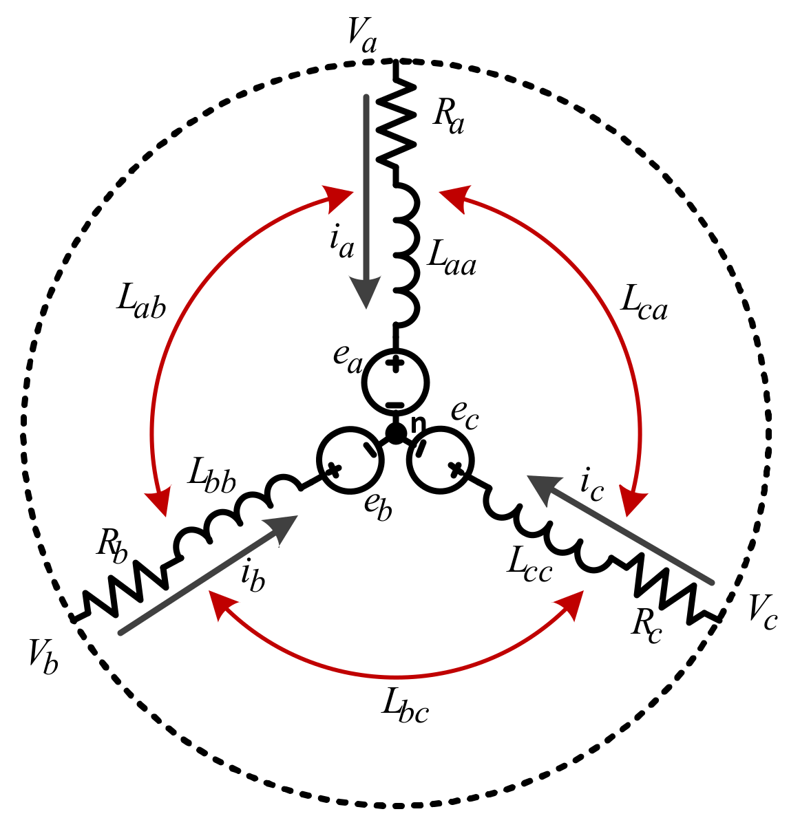
The equivalent circuit of a three-phase BLDC motor is shown in Figure 1. It should be assumed that the motor parameters were considered to be in ideal condition, i.e., the isotropic structure machine, ignoring the saturation of the iron core and armature reaction and disregarding the eddy current losses and hysteresis losses, as well as neglecting the power loss for power switches and flywheel diodes of the inverter. The dynamic model of a BLDC motor as related to the voltage equations of three phases can then be expressed as Equation (1) [21],
where Van, Vbn and Vcn are three-phase voltages; ia, ib, and ic are three-phase currents; Ra, Rb and Rc represent the phase resistance for each phase; Laa, Lbb, Lcc and Lab, Lbc, Lca, Lac, Lba and Lcb denote the self-inductance for each phase and the mutual inductance between each of the two phases, respectively; ea, eb and ec are the ideal three-phase BEMF. Considering a three-phase balanced system as the sum of three-phase currents equal to zero are satisfied , the stator voltages in Equation (1) can be rearranged into the matrix form as Equation (2):
where Rs = Ra = Rb = Rc, L = Laa = Lbb = Lcc, M = Lab = Lbc = Lca = Lac = Lba = Lcb and Ls = L − M.
In order to ensure ease of measurement, the L2L voltages in the practical applications in which the L2L voltages are approximately equal to the DC bus voltage when the power switches are turned on in its sequence order, the Equation (2) can be expressed under the L2L voltages form by subtraction calculation between the two-phase voltages as Equation (3):
The electromagnetic torque as the mechanical loss is ignored, Te in N-m, is given by Equation (4),
where is the mechanical angular speed in rad/s.
The relationship between the electromagnetic torque, the load torque, TL in N-m, and the motor speed known as the electromechanical system, the motion equation can be expressed by Equation (5),
where J is the moment of inertia, in kg-m2/s2 and B is the viscous friction, in N-m/rad/s.
2.2. The Motor Drive System Control
2.2.1. The 120-Degree and 180-Degree Conduction Modes
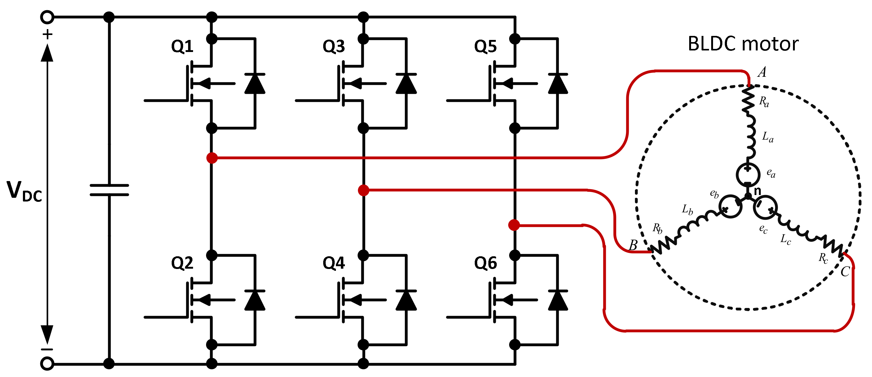
As mentioned in the Introduction, both the 120-degree and 180-degree conduction modes have the same three-phase inverter configuration, as shown in Figure 2. The two conduction modes were implemented by a soft-chopping technique in which the upper-side power transistors Q1, Q3 and Q5 were used to switch on or off, while the lower-side power transistors Q2, Q4 and Q6 were employed to send PWM signals. Each control mode was divided into six intervals for a 360-degree electrical cycle.
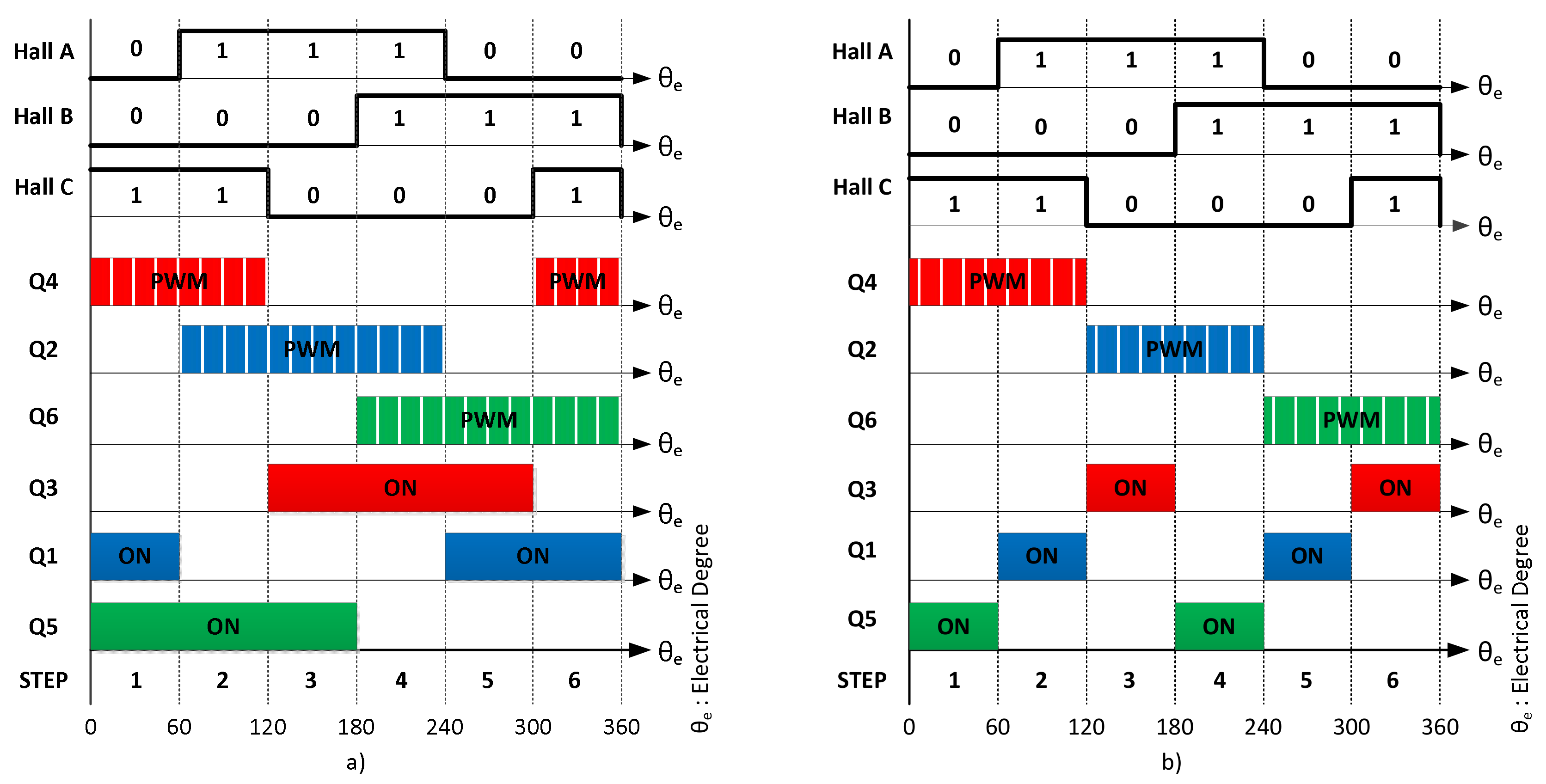
Figure 3 shows the Hall-effect based position information and the switching timing, respectively, for the 120-degree and 180-degree conduction modes. The conduction order of the power transistors, for both cases, was determined by the rotor position information which can be obtained by position sensors or sensorless position techniques. Consequently, the controller can track the switching sequence of the three-phase inverter according to the six conduction intervals so that the motor excitation current and the BEMF are in phase. These techniques were implemented in this paper for comparison purposes between the two modes and are discussed in the Experimental Results.
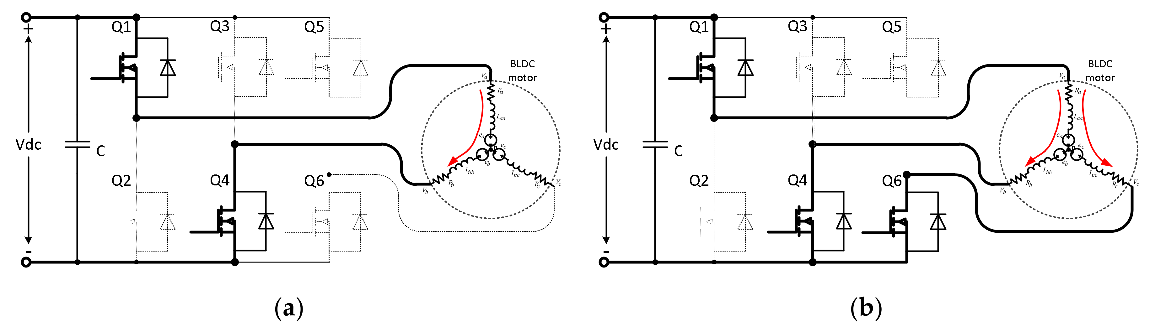
Figure 4 demonstrates the operating state configuration for a phase-conduction when the signals of Hall A, Hall B and Hall C were equal to 101 and 011 for both 120-degree and 180-degree conduction modes, respectively.
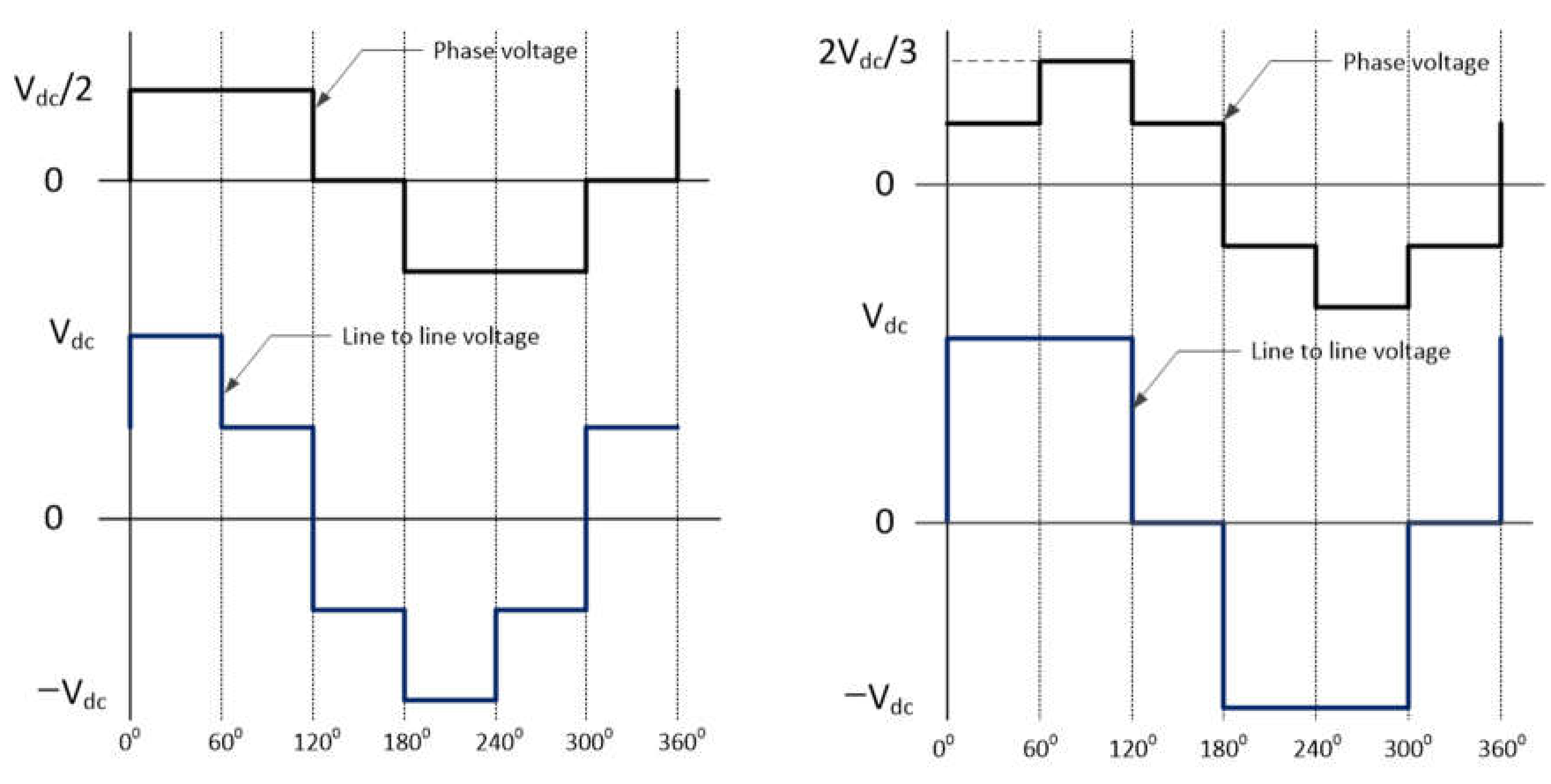
For the 120-degree technique, in this case, the current flowed through the two phases A and B from the positive end to the negative end of the DC bus while the remaining phase C was floated, as shown in Figure 4a. In this switching scheme, each phase per arm was switched on for 120 electrical degrees and switched off for 60 electrical degrees. The next switching state for phase B was that the power transistor Q5 was switched on for the next 60 electrical degrees. The phase voltage in this mode is [20], and its output voltage waveforms, the phase and L2L voltages, are shown in Figure 5a.
Unlike the 120-degree technique, for the 180-degree technique, the three phases A, B and C, are switched on at any time, as depicted in Figure 4b. This means that either the upper-side or the lower-side power transistors of the same arm are switched on at any one time. The current in this case flowed through from the positive end to the negative end of the DC bus. The current of phase A was equal to the sum of both phase currents B and C but inverse-sign. The value of the phase voltage in this mode is either or [20]. Its output voltage waveforms, phase voltage and L2L voltage are shown in Figure 5b. In comparison to the 120-degree conduction mode, the 180-conduction mode produced a higher current of about 4/3 times, and the generated torque was 35% greater with a power supply of the same voltage [16].
2.2.2. Speed PID (Proportional-Integral-Derivative) Control Scheme for 120-Degree and 180-Degree Conduction Modes
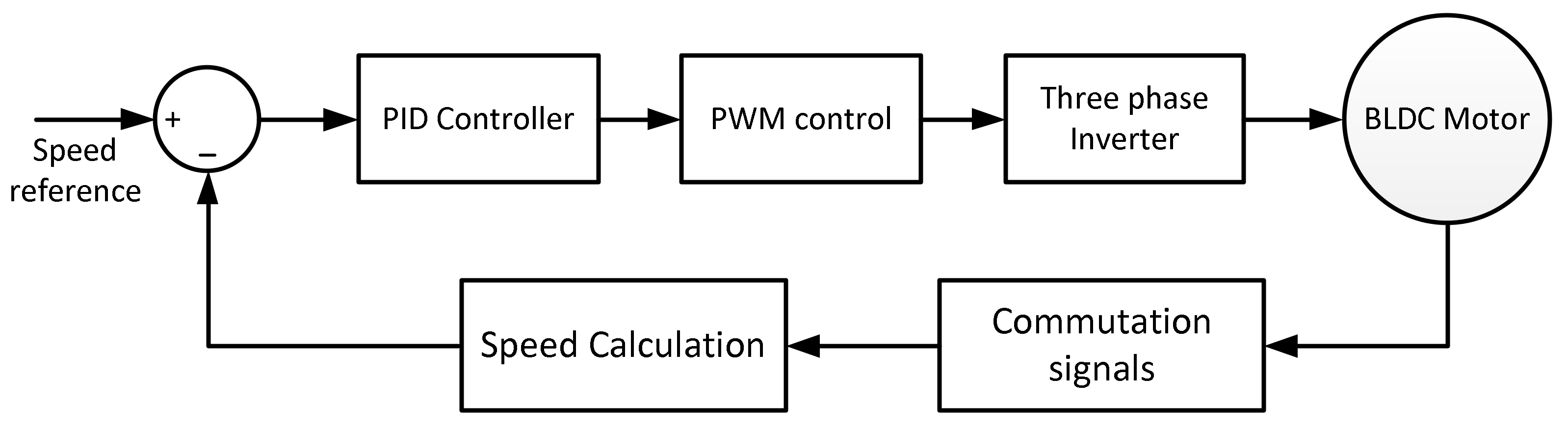
Generally, for a BLDC motor, the BEMF is directly proportional to the speed of the motor, and the torque production is almost proportional to the phase current [22,23]. Based on these features, the speed control scheme was designed, as shown in Figure 6. In this paper, a digital PID control algorithm was implemented to control motor speed for both the 120-degree and 180-degree conduction modes.
2.2.3. Design of Sensorless Circuit with Schmitt Trigger Circuit
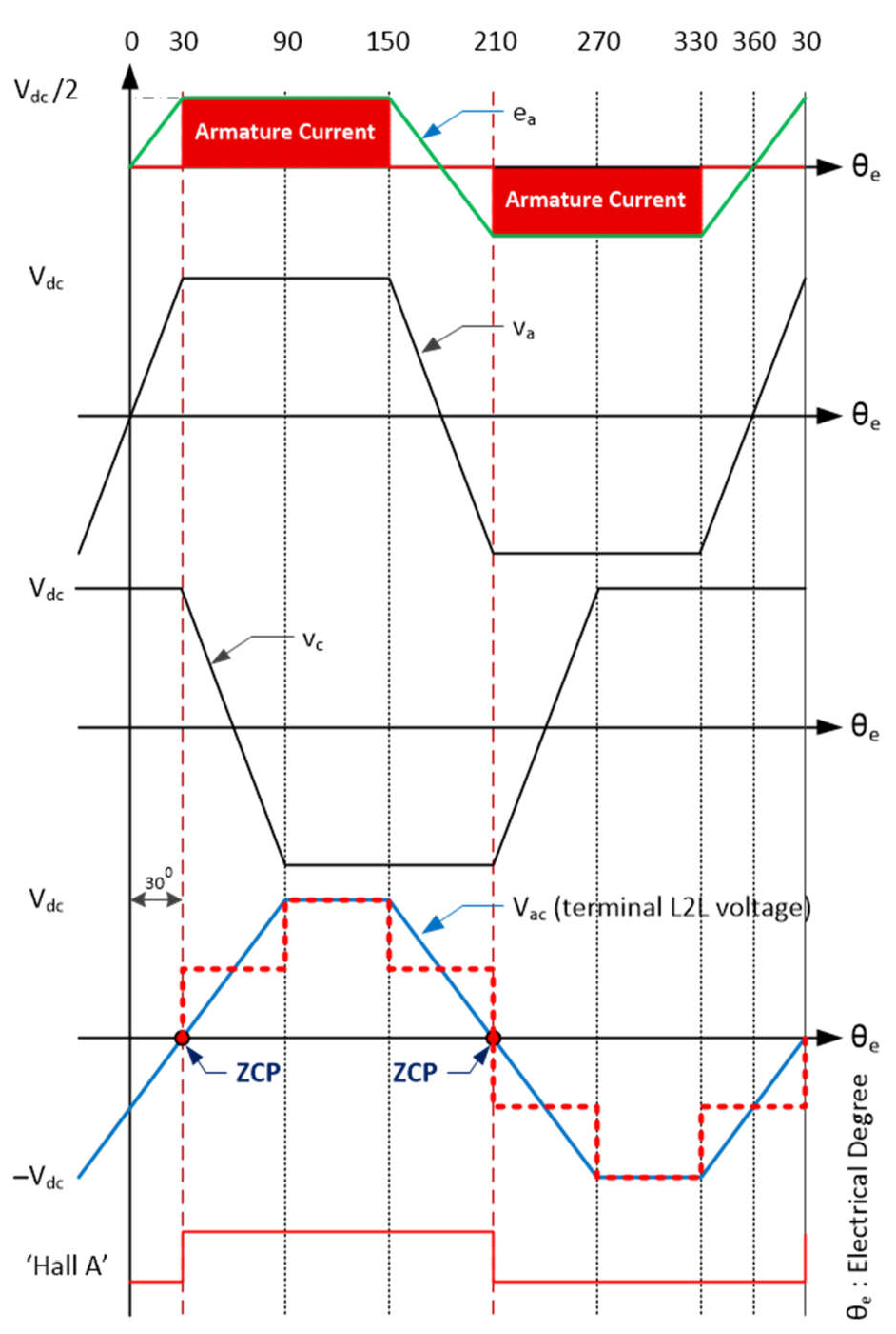
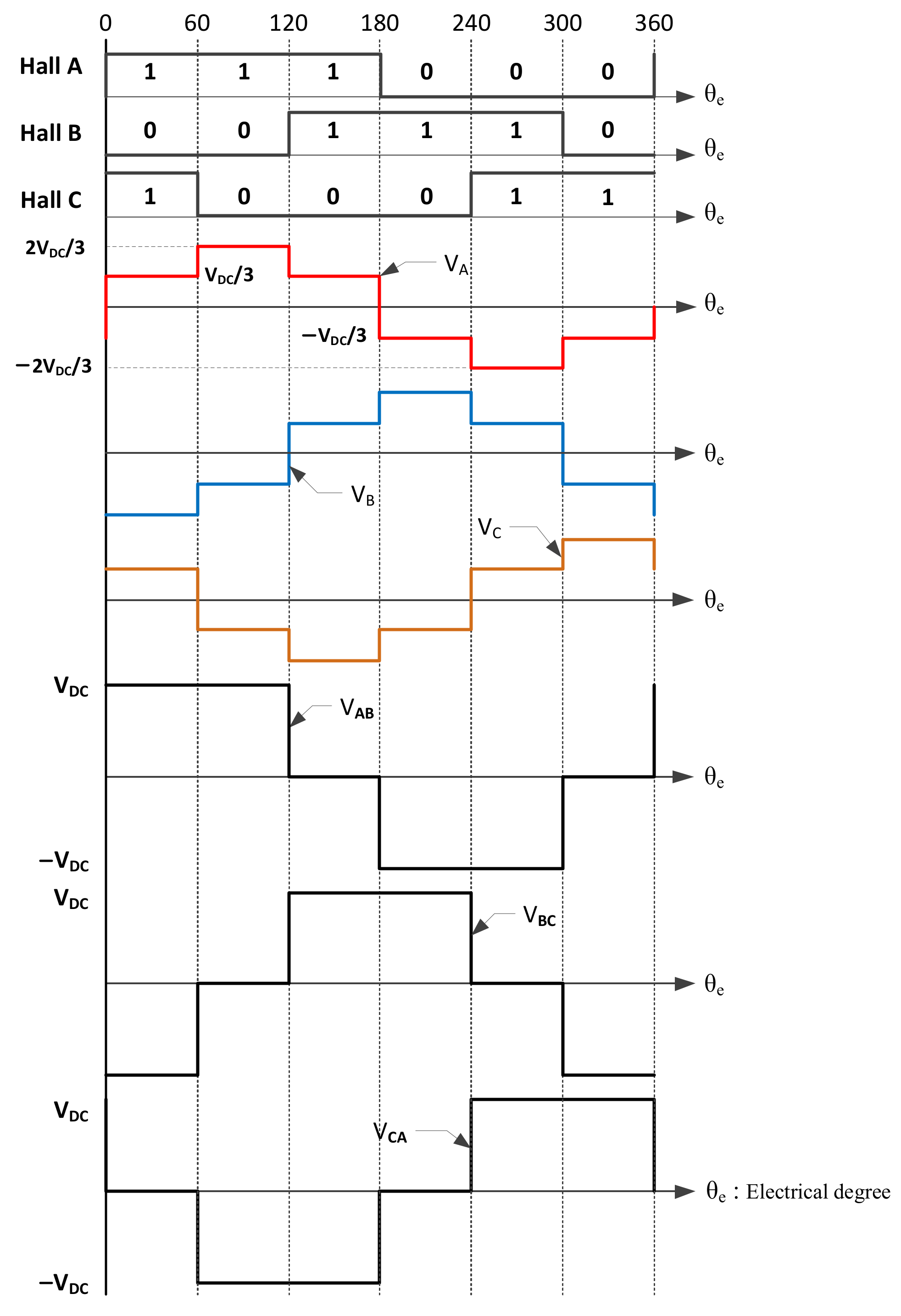
As mentioned in Section 2.1, for the dynamic model of the BLDC motor, the L2L voltages can be expressed as Equation (3) in which their average L2L voltages are used to obtain the SCSs. The sensorless commutation algorithm is described in [15]. The relationship between the ZCPs of the ideal BEMF, L2L voltages, the commutation points and the square-wave L2L output inverter for the 120-degree conduction mode is illustrated in Figure 7. It can be seen that the ZCP of the L2L average terminal voltage lags by 30 electrical degrees compared to that of the phase BEMF or the terminal phase voltage. The commutation points occurred at the same time of the L2L voltage ZCPs. This means that the ZCPs of the L2L voltage were in phase with the ideal commutation points. The average L2L voltage can be expressed as Equations (6) and (7) [15]
where, D is duty ratio (e.g., D = 50%); is electrical degree; and is the DC bus power supply.
The red dash-line in bold shows the ideal waveform of the average L2L voltage, which was calculated from Equations (6) and (7), corresponding to the given switching intervals. This implies that the ZCPs of the L2L voltage are in phase with the ZCPs of the L2L voltage inverter outputs.
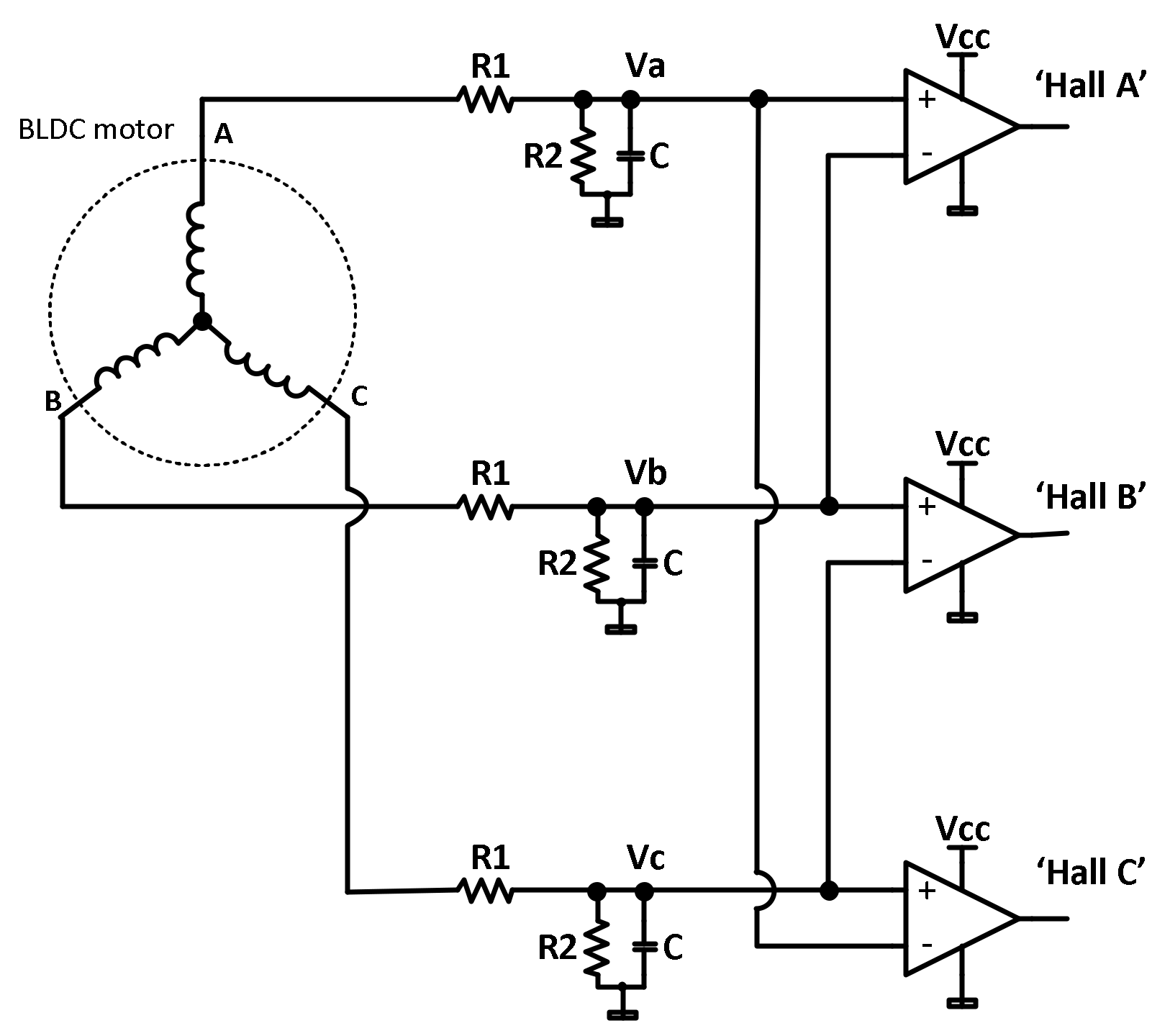
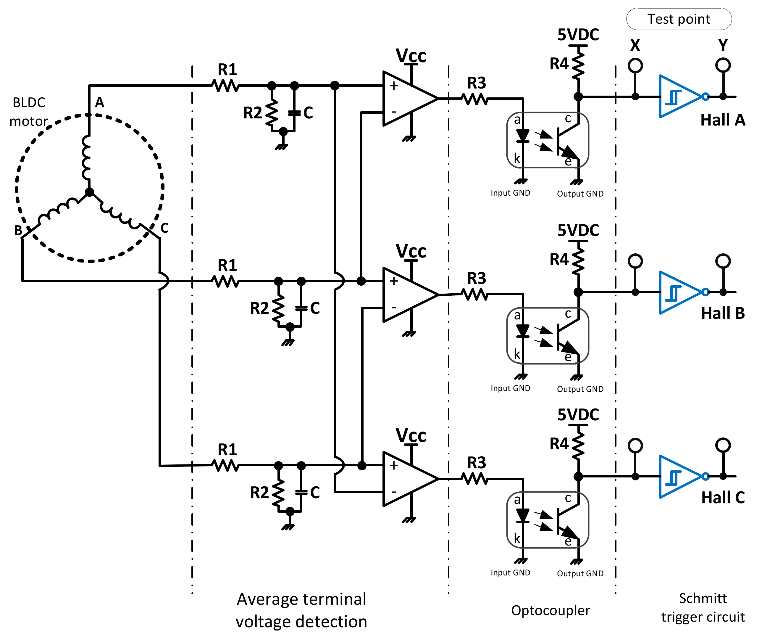
Consequently, the Hall sensorless signals based on the L2L average terminal voltage were implemented in this paper, as shown in Figure 8 [10,15]. The commutation signals were directly extracted from the three terminal voltages, VA, VB and VC, and passed through a comparator. In order to eliminate the noise at the terminal voltages, low-pass-filters (LPFs) were used. The LPFs’ outputs, which were adopted from the three terminal voltages, were connected to the non-inverting pin of the comparators. The inverting pins of the comparators were linked suitably to any remainder terminal voltages to detect the ZCP of the average L2L voltages.
In addition, in this sensorless scheme, the design of the LPF is very important because it is related to the cutoff frequency required for a specific application. In a normal case, an LPF with a high cutoff frequency is often used because of its decreasing lagging purpose. However, this selection should be carefully considered if a high-speed and high-power BLDC motor is used because its electromagnetic interference is large [10]. The transfer function, G(s), of the LPF can be expressed in Equation (8) with the cutoff frequency, , and phase delay, expressed in Equations (9) and (10), respectively [10,15].
where, and are the voltage dividers, C is the filter capacitance, is the angular velocity of the motor and s is the Laplace operator.
In [10], a heavy LPF was adopted for a high-speed and high-power BLDC motor; however, it could not be implemented in this application. Accordingly, in this paper, the design parameters of the LPFs and the input for the comparators are presented in Table 1. These LPFs adopt a high cutoff frequency. This causes a large noise at the motor terminal voltage. Therefore, in order to operate with these LPFs’ parameters, the sensorless circuit needed to have a Schmitt trigger circuit added to remove noise suppression as well as reshape the commutation signals. A Schmitt trigger circuit might have been used before, but this has never been stressed in previous literature. Consequently, an analysis of the role of the Schmitt circuit was necessary, and the results are discussed in the Experimental section. Moreover, due to safety reasons, an optical-coupler was also added to the circuit to isolate the microcontroller from the sensorless circuit. Lastly, in order to get a response time and frequency response that was suitable for this application, the input-resistor and the load-resistor were designed to be equal to each other, = = 10 kΩ. Figure 9 represents the practical circuit that was successfully implemented for a 120-degree conduction mode in this paper.
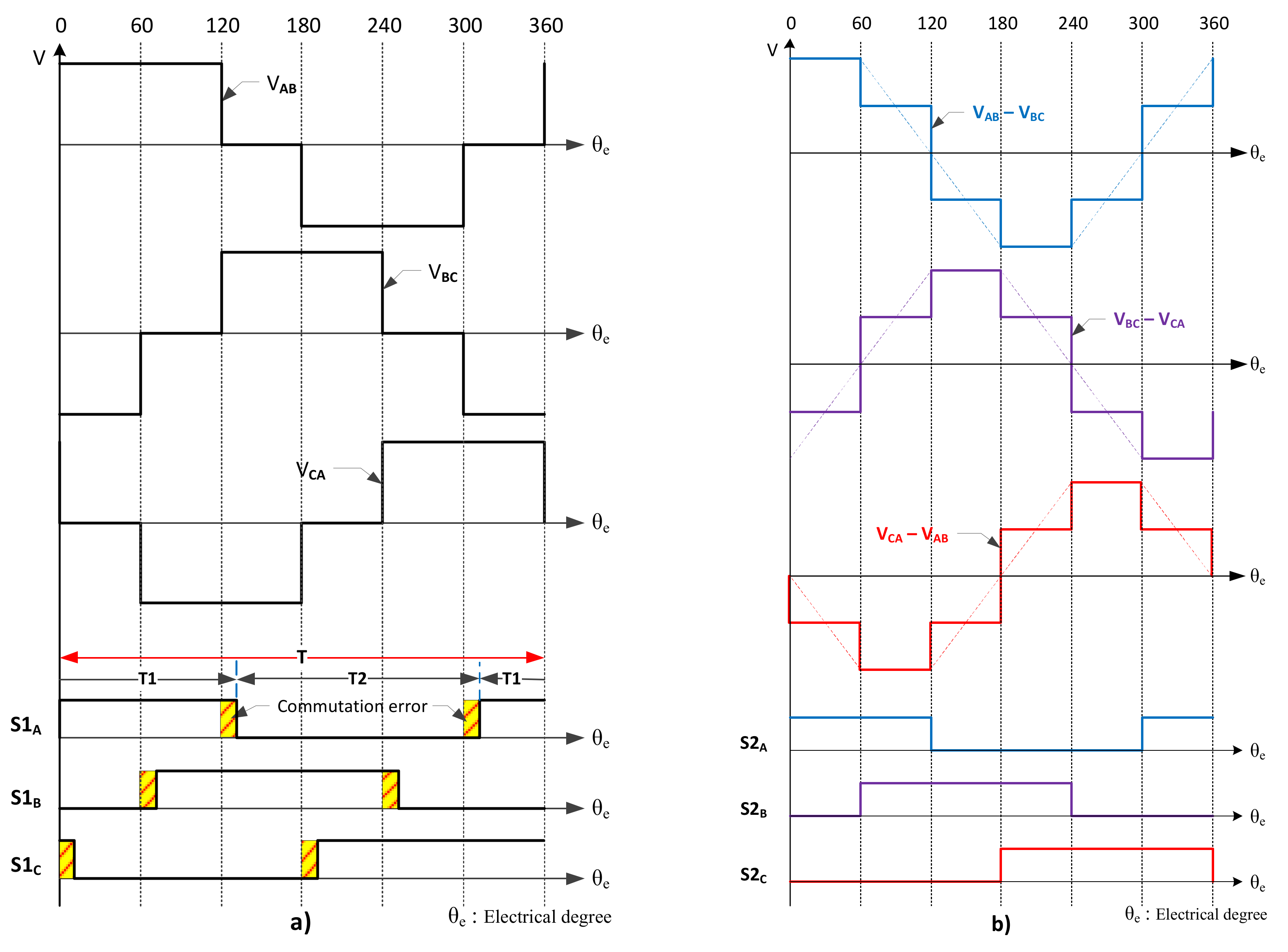
For a 180-degree conduction mode inverter, a difference was observed in the output of the L2L voltage waveform as compared with the 120-degree mode, as shown in Figure 5. Theoretically, its ZCPs could have appeared at any time during the intervals from 120°–180° and from 300°–360° electrical degrees. As a result of this, the SCSs may have been improper. This means that a commutation error could have occurred at the rising edge or falling edge of the SCS or at both edges. This may have been because of the electromagnetic transient, the selected-resistance values of the voltage divider or errors caused by the devices, related to the sensorless circuit. Figure 10 shows the relationship between the Hall-effect signals, the output waveforms of the phase voltage and the L2L voltage of the 180-degree conduction inverter. It can be seen that the SCSs of phase A occurred at the ZCPs of the terminal phase voltage instead of the terminal L2L voltage. Therefore, the sensorless circuit, which is proposed in Figure 9, could not be adopted in this case.
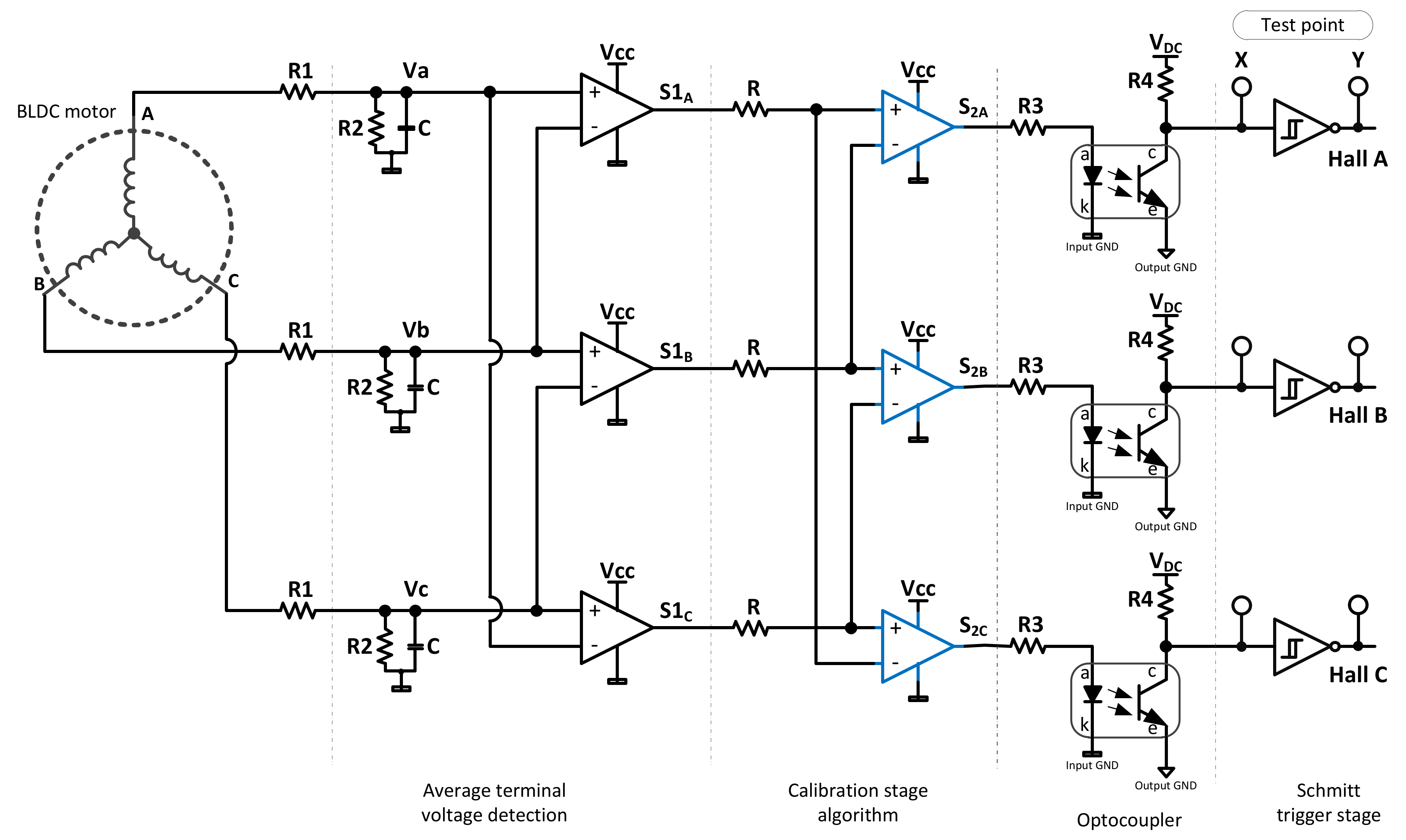
Figure 11a illustrates the SCSs which were obtained using the terminal L2L voltage method depicted in Figure 9, while Figure 11b shows the SCSs acquired from the proposed sensorless circuit. It can be seen that the error of the commutation signal, i.e., S1A at the Y-testing point, which was the output of the comparator, would have occurred at the intervals of 120°–180° and 300°–360° electrical degrees. As a result of the period of conduction-time, it may be the case that either T1 is equal to T2 or T1 is greater than that of T2, or the reverse may be true. In this demonstration, T1 was equivalent to T2. This led to the degradation of the motor drive’s overall performance. Accordingly, in order to solve this phenomenon, a novel sensorless circuit was proposed, as in Figure 12, with a simple algorithm. First, the SCSs, S1A, S1B, and S1C, which were obtained from the comparator at stage 1 and could be supposed as the L2L voltage outputs of the inverter, could be passed through the comparator at stage 2 to compare the voltage signals, VAB − VBC, VBC − VCA and VCA − VAB. The ZCPs obtained from these comparison signals were the SCSs S2A, S2B and S2C, as shown in Figure 11b. Table 2 shows the summaries of the inputs of the comparator for the proposed sensorless circuit.
3. Description of the System Hardware and Software
3.1. System Hardware Design
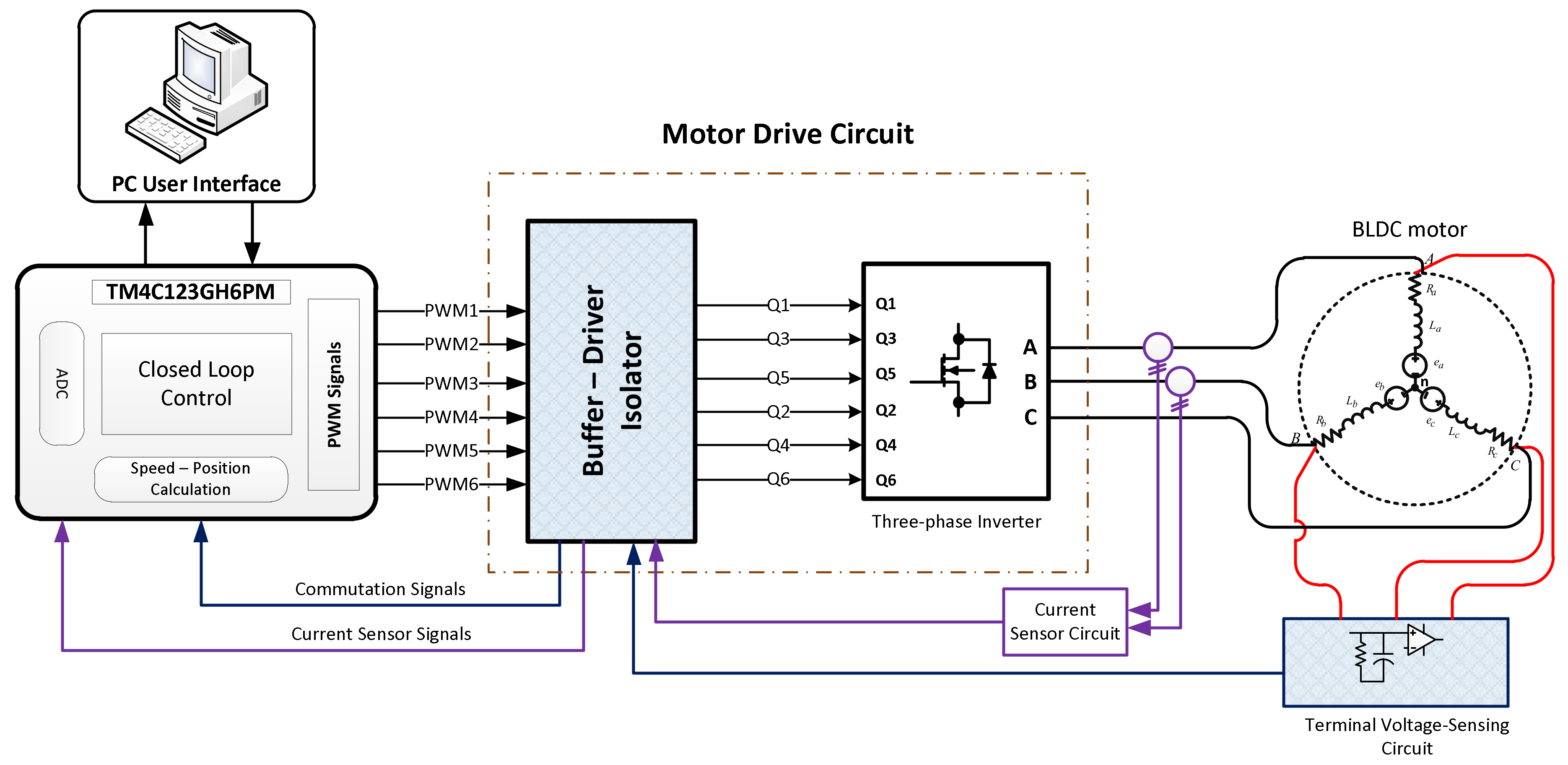
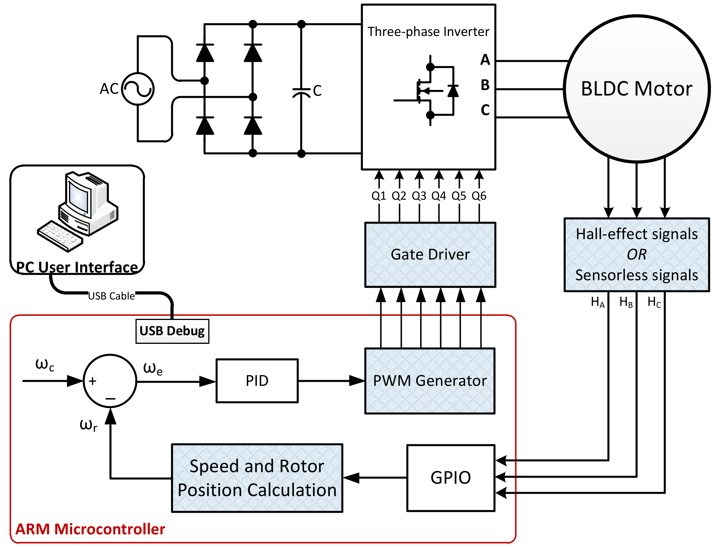
Figure 13 demonstrates the function block diagram of the system hardware architecture designed in this paper that was implemented for the power tool with both a Hall-effect position sensor control and a sensorless control.
The system hardware of the power tool motor drive was based on an embedded ARM microcontroller 32-bit TM4C123XXX which integrated a Tiva-C series Launchpad evaluation board, and other peripheral devices. The Launchpad is a low-cost evaluation platform for TM4C123XXX microcontroller, which is manufactured by Texas Instruments Inc. (Dallas, TX, USA), has a core of ARM Cortex-M4 and a DSP arithmetic unit. Its specifications comprise an on-board in-circuit debug interface (ICDI), a USB 2.0 device interface, a hibernation module and a motion control PWM module. The peripheral devices included an AC/DC rectifier, a three-phase inverter, a buffer-stage circuit, a voltage detection circuit, protection circuits, a power supply and a prototype of the power tool. The power supply was used to feed to the DC bus of the inverter. The inverter was configured as shown in Figure 2 with six power-MOSFETs (metal-oxide-semiconductor field-effect transistors) that were commutated sequentially according to the designed switching pattern. The buffer circuit was built to protect and separate the peripheral devices and the microcontroller and separate the power stages which had different voltage levels. The voltage detection circuit was used to obtain the SCSs. The protection circuits were employed to defend short-circuit, over-load and power-switches. Those peripheral devices were integrated into a motor drive circuit board.
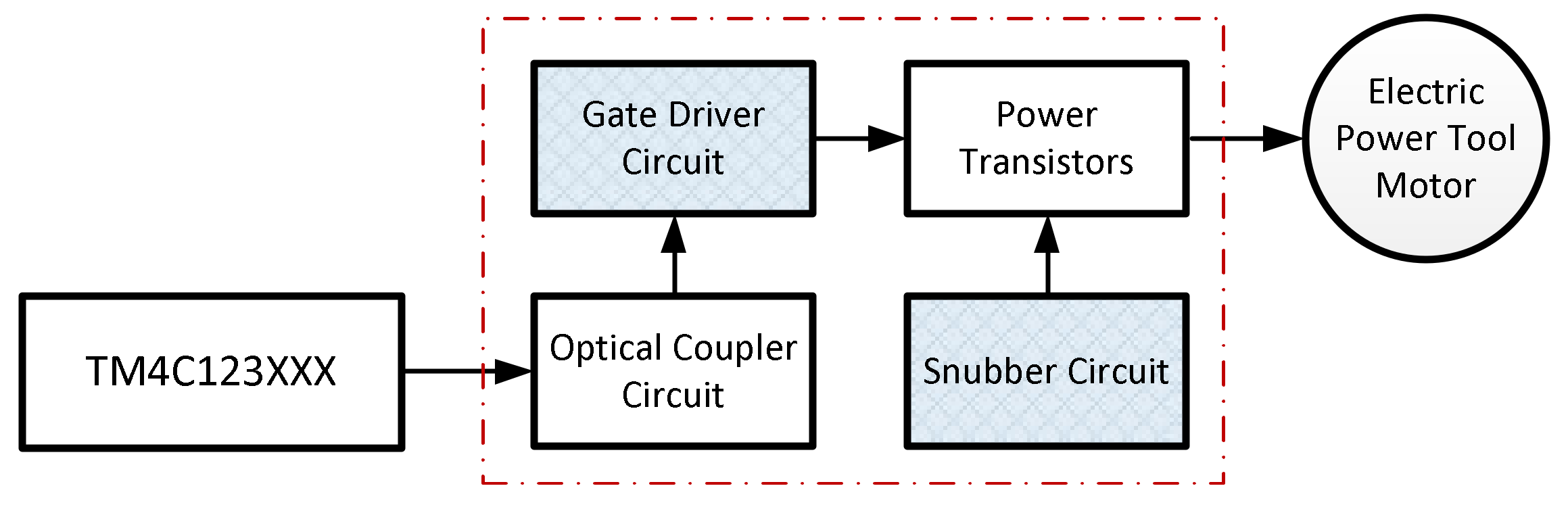
The motor drive circuit board designed in this paper included two parts. The first step was to convert the 110 V AC input power line to output voltages of 5 V DC and 15 V DC by employing a bridge rectifier and filter. The second was the optical isolator, gate driver circuits and three-phase inverter protected by the snubber circuit. Figure 14 shows the detailed block diagram of the motor drive circuit module. It included an optical coupling isolation module and a gate driver module. The optical module was used to separate the 5 V and 15 V voltage sides. This was to prevent the high-side current from flowing back to the microcontroller. In order to avoid a short circuit or cross-conduction phenomenon with the 180-degree conduction mode of the power transistors in the same arm, the IR2103-based gate driver module was applied to control the gate signals of the power MOSFETs. In addition, the snubber circuit provided a path for the current to pass through and quickly reduced the voltage of the power MOSFET during the moment of switching at high frequency in such a way as to decrease the switching loss, switching noise and electromagnetic interference and increase the component’s lifetime.
3.2. Development of System Software
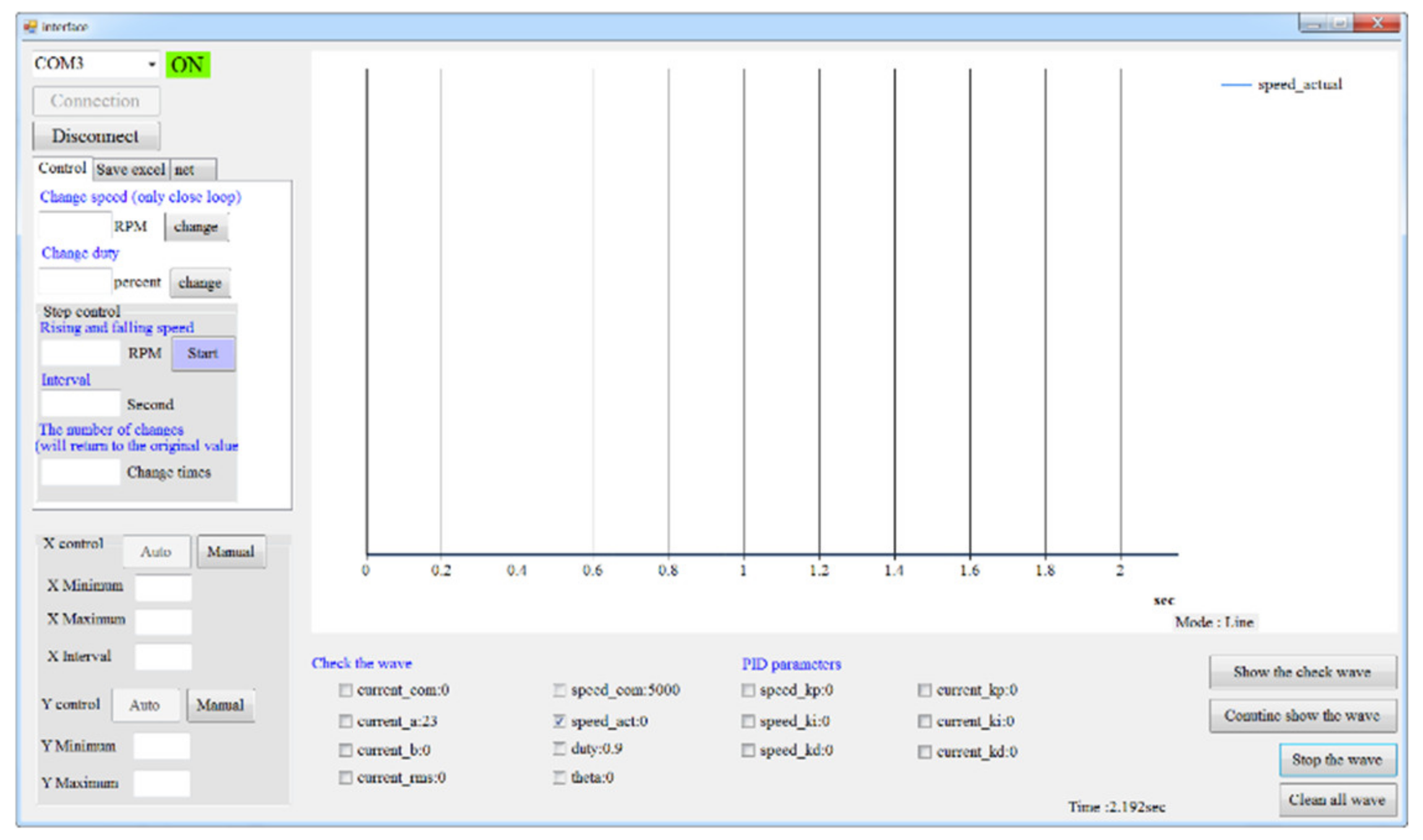
The system software was developed under the Cortex M4 development environment and written in C language. The firmware of the motor drive was programmed based on the Keil integrated development environment tool developed by the Keil company. The firmware contained modules including sensorless starting open-loops, PWM generation, rotor position calculation, motor current measurement and speed calculation. In addition, a graphical user interface (GUI) was also designed using the Microsoft Visual Studio 2017 C# (Microsoft, Redmond, WA, USA) development platform, as shown in Figure 16. The GUI was used to set the command and monitor data such as motor speed, currents, duty cycle and PID parameters. These data can also be stored in the PC in the Excel format.
3.2.1. The System Software Architecture
The system software architecture that was applied for both methods of Hall-effect based position sensor control and sensorless control is shown in Figure 17. The motor speed and rotor position information were calculated based on the SCSs (HA, HB, HC). The speed error, , was the result of a subtraction between the estimated actual motor speed, , and the command speed, . This speed error was passed over to the speed PID controller to update the PWM duty cycle.
Regarding the sensorless case, when the BLDC motor was at a standstill, there was no BEMF voltage induced in the motor windings. Thus, the method of detecting the position of the rotor at this stage without the position sensor was invalid. Accordingly, in this paper, the open-loop method was implemented to start the motor until the BEMF could be detected by the L2L voltage sensing circuit. At the beginning, the PWM signals were sent to any phase from the motor by the microcontroller according to the pre-set commutation signals. As the motor rotated, the motor stator generated a rotating magnetic field to drive the rotor magnetic pole. Then, the frequency of the rotating magnetic field and applied voltage were both gradually increased while maintaining a constant magnetic field. When this was significant enough to overcome the moment of inertia and friction of the rotor, the rotor rotated synchronously with the magnetic field to achieve the starting procedure. Consequently, the open-loop was terminated, and the motor operation was switched to the sensorless operation mode.
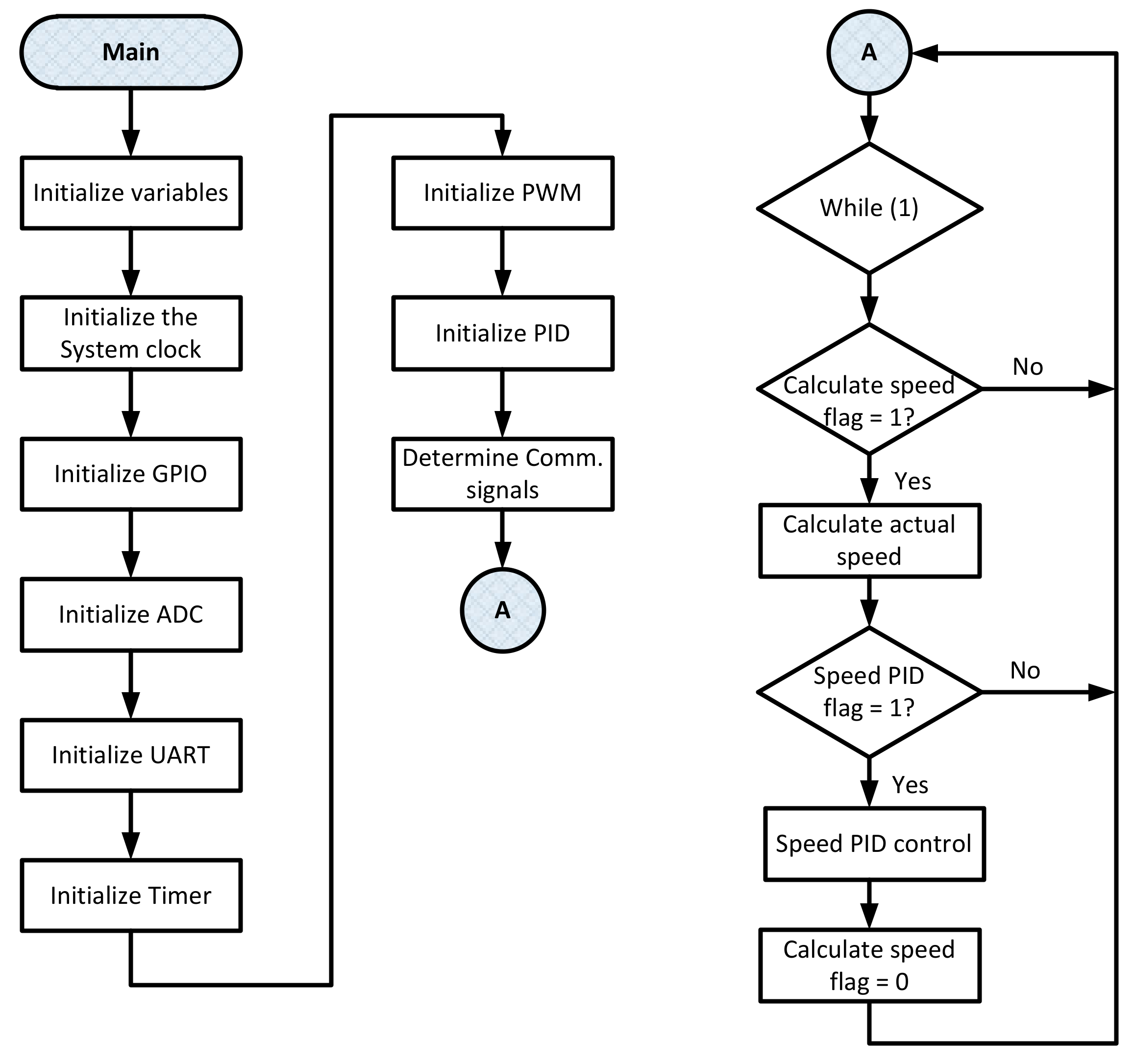
3.2.2. Flowchart of the Main Program
The flowchart of the main program is shown in Figure 18. When the program started execution, firstly, the memory and the interrupt vector table were initialized and set, respectively. The main program then initialized the variables, the system clock, control parameters and interrupt priority. Subsequently, it read the rotor position information which was generated from either the Hall-effect sensors or the sensorless method, and the MOSFET was switched on. Afterward, the main program entered the while loop and checked whether the speed calculation flag was raised or not. If the flag was raised, the motor speed was calculated. The next step was to confirm whether the speed PID flag was set or not. If the flag was set, the speed PID control was performed. The program was designed to set up the speed flag for every 2 ms. After the speed PID was executed, the PWM duty cycle could then be updated. The corresponding signal according to the PWM duty cycle was sent out to control the conduction of the power MOSFET.
4. Experimental Results and Discussion
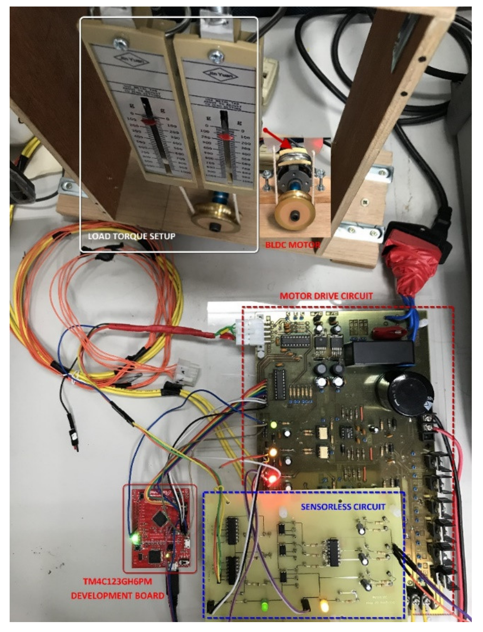
An experimental testing platform of a power tool based on an ARM microcontroller was designed and implemented successfully in this paper, as shown in Figure 19. It consisted of an ARM development board by employing a TM4C123XXX microcontroller, a designed motor drive, a high-speed BLDC motor, a spring-scale load-torque system and a DC bus supply voltage source. The specifications of the BLDC motor for power tools are listed in Table 3. The BLDC motor drive system for both a Hall-effect based control and a sensorless control are depicted in Figure 13.
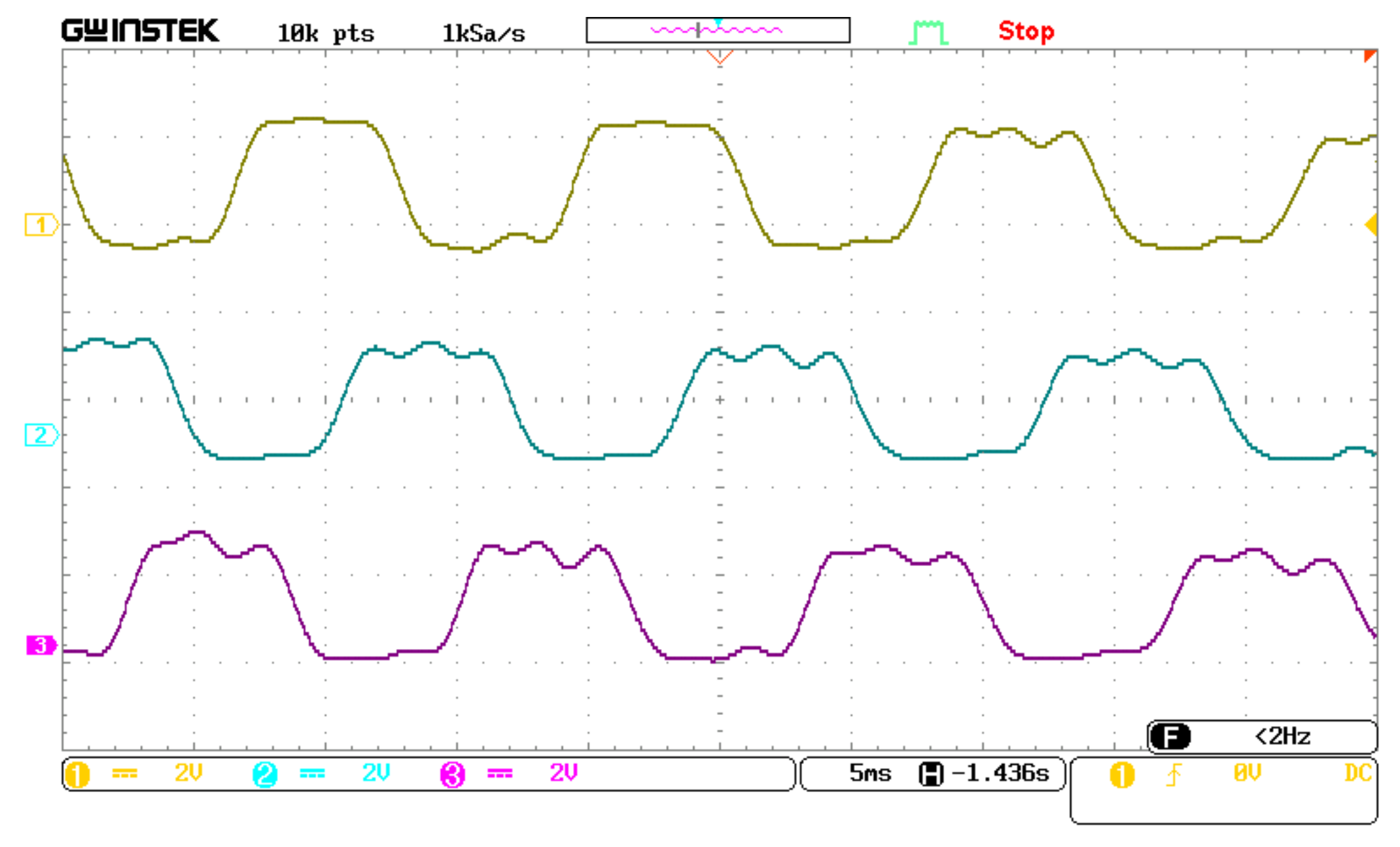
Figure 20 shows the BEMF trapezoidal waveforms of the power tool. Ch1, Ch2, and Ch3 represent the BEMF waveforms of the A-phase, B-phase, and C-phase, respectively.
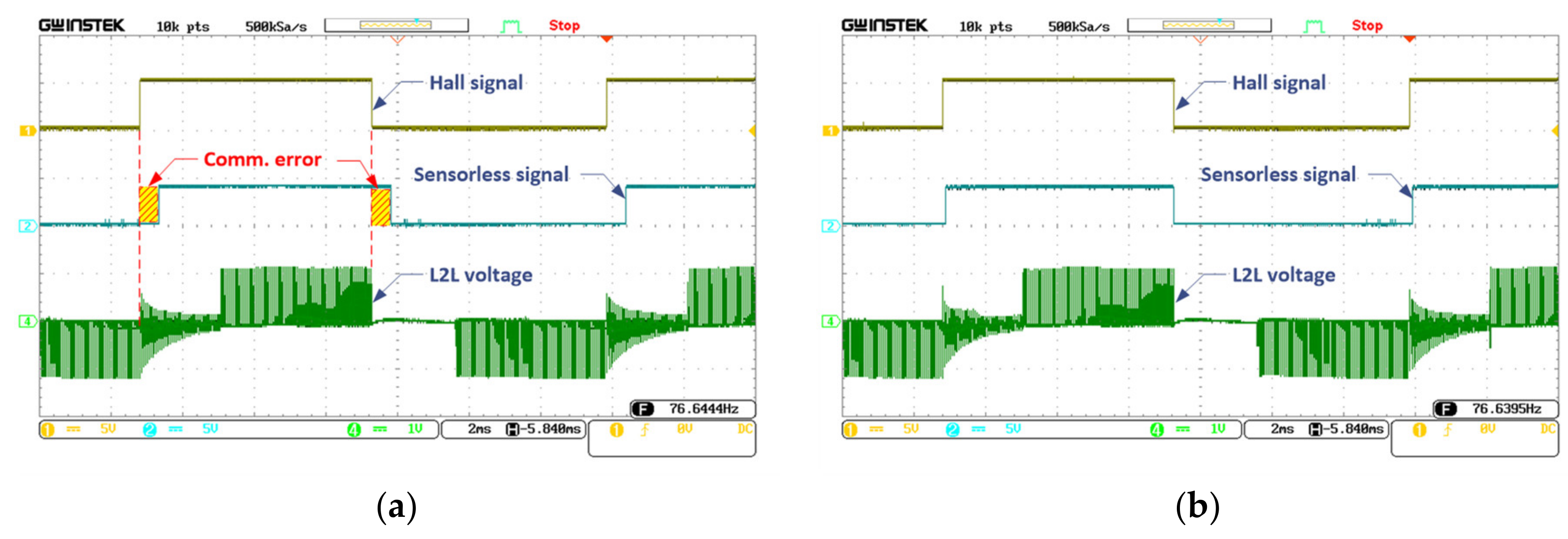
In order to verify the proposed sensorless circuit, in the first test, the SCSs’ experimental results with and without the proposed circuit were performed to compare with the theoretical analysis. Figure 21 shows the Hall signal and SCS of phase A, and the terminal L2L voltage was measured with and without employing the proposed sensorless circuit. It can be seen that both the rising edge and the falling edge of the commutation signal could be transited earlier instead of retarding by about 15 electrical degrees, as shown in Figure 21a. Figure 21b indicates the improved signal of SCS after applying the proposed sensorless circuit. These results are suited to theoretical analysis. It was noticed that the SCS passed through a buffer to get sharp-edge transitions for easy monitoring purposes.
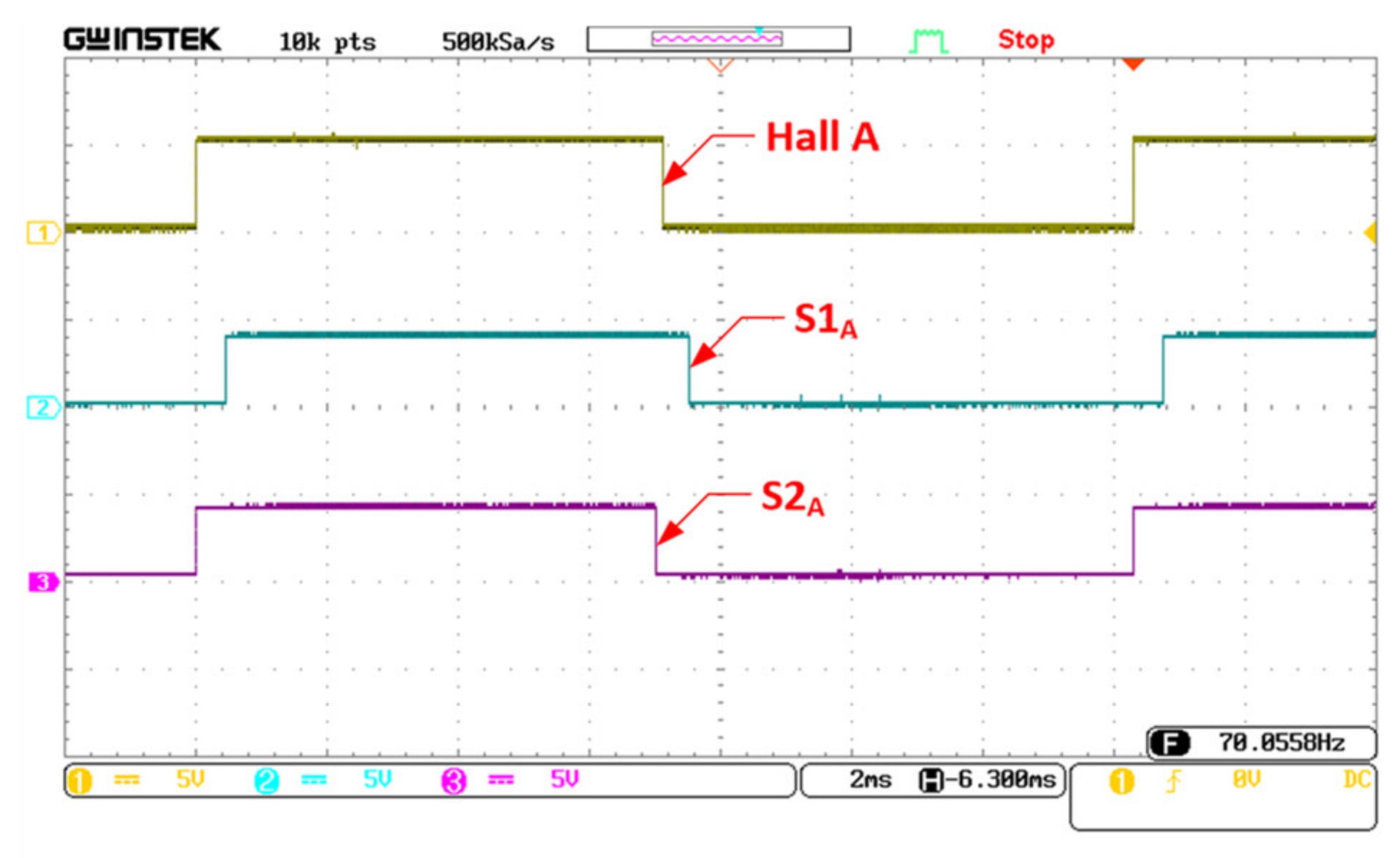
Furthermore, Figure 22 demonstrates the comparison between the Hall signal and SCSs at test points S1A and S2A implemented with and without the proposed circuit as depicted in Figure 12. It can be seen that the commutation signal from the proposed sensorless algorithm was correct.
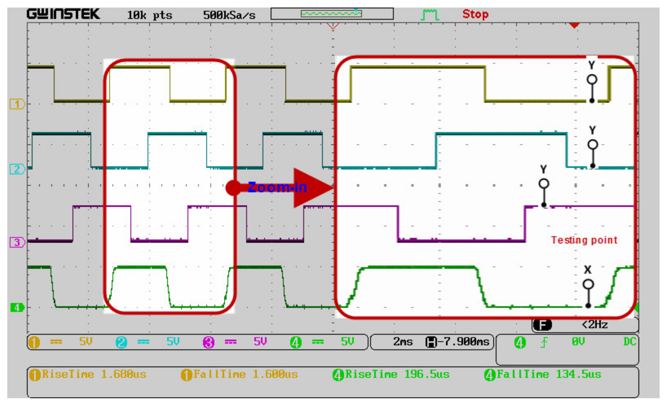
The system’s stability and performance were affected by the qualities of the SCSs, which were related to the rising edge and falling edge of the signals. In the second test, in order to improve these factors, the Schmitt trigger circuit was adopted for the designed sensorless circuit. Figure 23 demonstrates the SCSs measured with and without the inclusion of Schmitt trigger circuits. Ch1, Ch2 and Ch3 indicate excellent SCSs obtained by including the Schmitt trigger action according to phase A, phase B and phase C, respectively. Ch4’s SCS was extracted from phase A which was not implemented by employing the Schmitt trigger operation. It can be seen that the signals with Schmitt trigger action had a sharp shape on both edges and a rising time of 1.68 μs and falling time of 1.6 μs, respectively. On the contrary, without employing the Schmitt trigger circuit, the rising time and falling time were 196.5 μs and 134.5 μs, respectively. Moreover, the Hall sensorless signals that were not reshaped by the Schmitt trigger action may have caused an unstable operation for the microcontroller to generate improper PWM signals for switching.
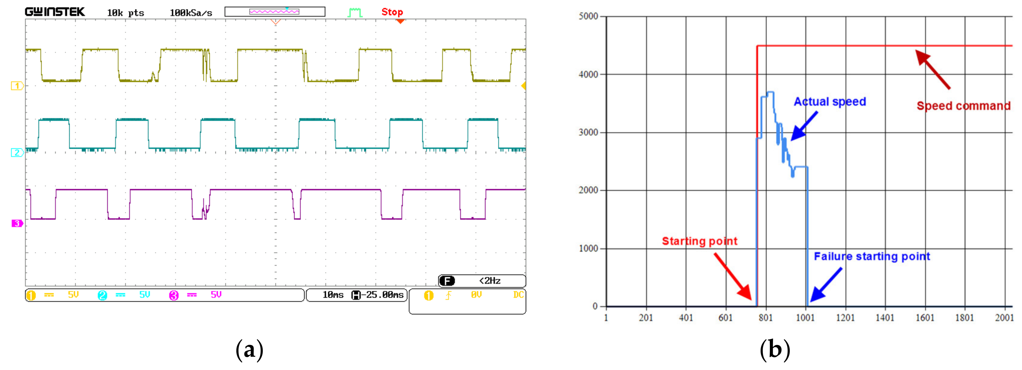
In order to verify the realization of the Schmitt trigger circuit, Figure 24 shows the results of the SCSs and the failure of motor starting without the Schmitt trigger. Figure 24b shows that the actual speed significantly fluctuated in the interval time between seconds 801 and 1001. In this case, the motor starting failure was caused by unstable SCSs, as shown in Figure 24a. It can be seen that the unstable SCSs were caused by noise at the terminal voltages of the motor during the starting procedure, which operated with the LPFs’ cutoff frequency of 1.5931 kHz, while the opposite results were achieved when the Schmitt trigger was included, as shown in Figure 23. However, the motor starting was successful at the cutoff frequency of 35.4543 Hz without the Schmitt trigger. Therefore, the design of LPFs should be carefully considered for certain applications. This finding may be useful for researchers who are considering whether or not to implement a Schmitt trigger circuit for their sensorless motor design. Summaries of some cases with different cutoff frequencies which were studied with and without a Schmitt trigger circuit are shown in Table 4.
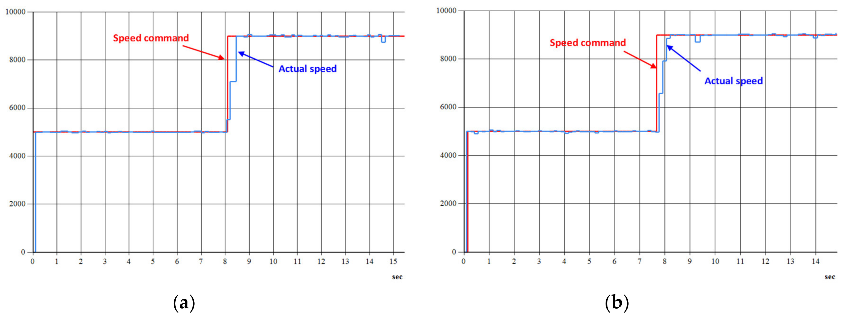
In order to distinguish the performance of speed response with Hall-effect position sensors from that without Hall-effect sensors, Figure 25 demonstrates the profile of the speed step response from 5000 rpm up to 9000 rpm, correspondingly, for the two cases. The solid straight line represents the speed command and the fluctuation line represents the real-time speed for each both figure. The time at which the actual speed reached the command speed was about 0.4 s for the two cases. This indicates that the sensorless position control addressed in this paper could replace the Hall-effect position sensor in the design of power tools’ BLDC motor drives.
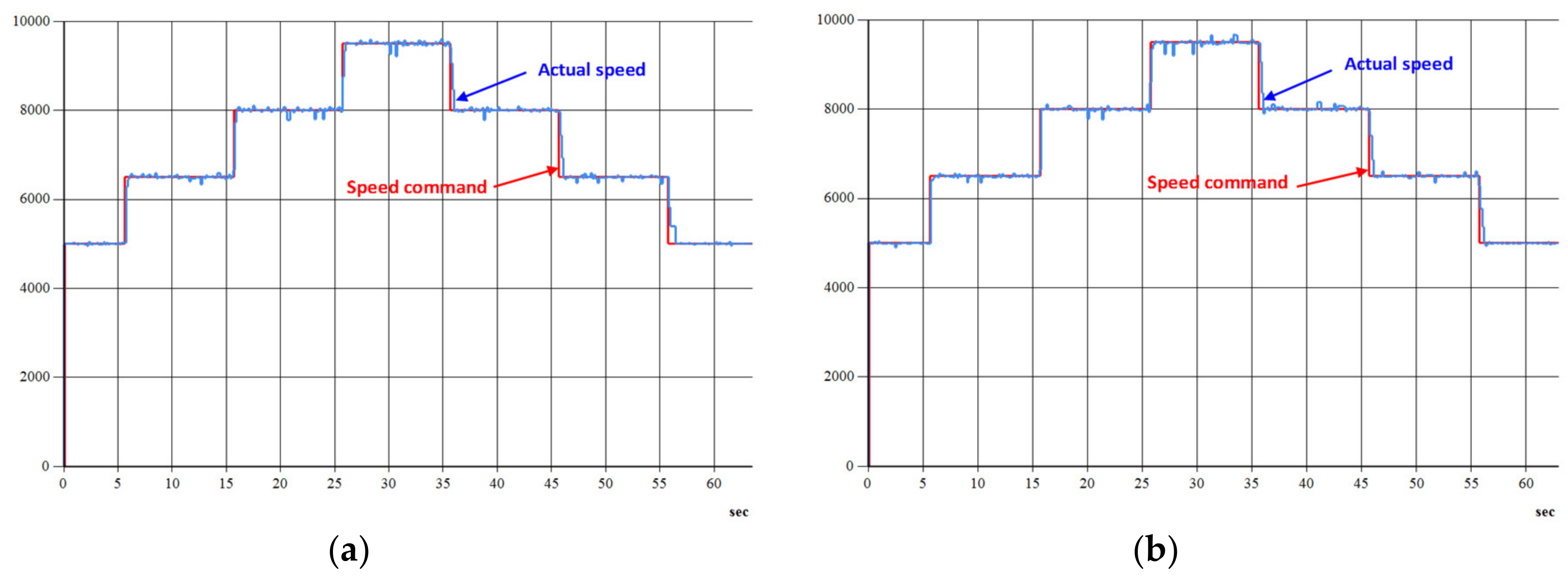
Moreover, to verify the speed response of the designed system with a sensorless position control, in which the speed response profiles are the same for stepping-up and stepping-down, it was tested with different speeds of 5000 rpm, 6500 rpm, 8000 rpm and 9500 rpm. The results were compared with those of the Hall-effect position control. Figure 26 shows the speed responses for both cases with and without using Hall-effect position sensors, respectively. The interval time was set as 10 s. From the observation of both figures, it can be found that actual speeds could catch up with speed commands and remain stable in the operation range. This inherently indicates that the sensorless position control proposed in this paper is feasible and of fidelity. However, there was a fluctuation of actual speed at high speed, and this is a challenge for the 180-degree conduction mode [17]. This is also a drawback of conventional PID control. Therefore, an intelligent PID should be employed in this case.
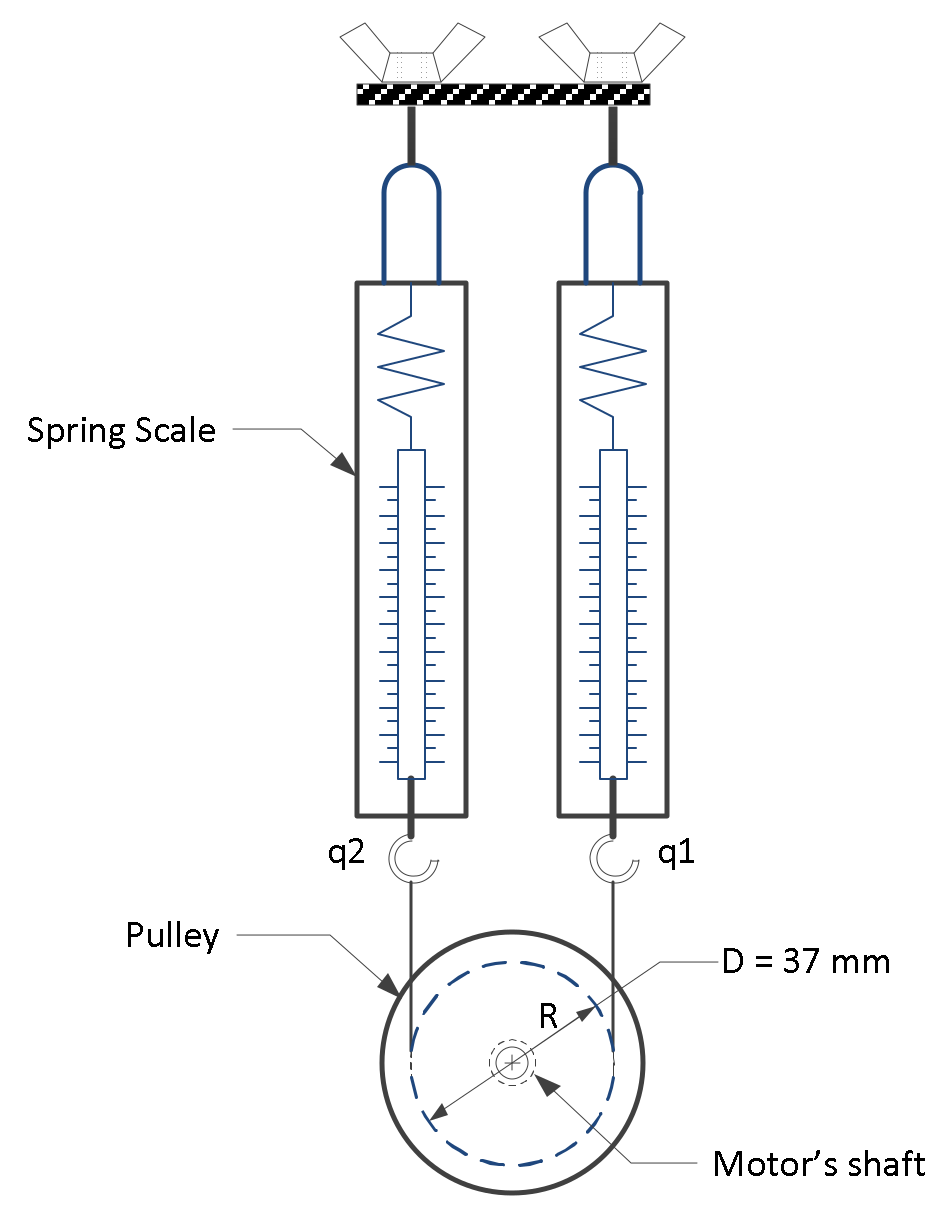
As mentioned in Section 2.2.1, in order to verify and compare the values of the currents between the 120-degree and the 180-degree conduction modes, in which the 180-degree mode was expected to give a higher power with the same power supply [16], the test was performed under different operating speeds for both modes in the Hall-effect position control and sensorless position control. The value of the DC bus voltage was 24 V. The RMS (root mean square)-current values were tested under the same conditions for both cases with and without Hall-effect sensors. A light load, = 0.0181 N-m., was coupled to the motor shaft, as shown in Figure 15. The results are shown in Table 5. Accordingly, it was found that the current values of the 180-degree conduction mode were larger than those of the 120-degree conduction mode by about 1.3333 times [16]. This was because the RMS phase voltage value of the 120-degree mode was smaller than that of the 180-degree mode. Secondly, the total impedances for the 180-degree mode were smaller than those of the 120-degree mode, in which the two phases A and B were connected in series for the 120-degree mode, while for the 180-degree mode, phase A was connected in series with phase B and phase C in parallel.
5. Conclusions
A 180-degree conduction mode, rather than a 120-degree conduction mode, for a power tool’s sensorless motor drive based on the ARM microcontroller was designed and implemented successfully in this paper.
In order to obtain stable sensorless commutation signals from the average terminal L2L voltage sensorless method, an improvement with a Schmitt trigger circuit was designed and implemented successfully in this paper. The experimental results show that the sensorless commutation signals generated from the proposed method had not only a sharper edge but also reduced noise signals as well as increased stability of system operation. This finding might be useful for researchers who are considering whether or not to implement a Schmitt trigger circuit for their sensorless motor design. Moreover, it is impossible to measure phase BEMF from the motor terminal directly for the 180-degree conduction mode because there is no floated-phase in this mode. Therefore, the terminal L2L voltage sensorless method is suitable to adopt in the 180-degree conduction mode. However, its terminal L2L voltage is different from the 120-degree conduction mode. This leads to the ZCPs of the sensorless commutation signals generated by the conventional terminal L2L voltage method being unstable or improper. Consequently, a novel terminal L2L sensorless circuit is proposed in this study to handle this phenomenon. The experimental results show that the proposed method gave good performance and replaced the installation of the Hall-effect position sensors. In other words, it not only helps to resolve the drawbacks of a motor drive installed with the Hall-effect position sensors, such as the degradation of performance due to variations in temperature and harsh environments, but may also reduce the overall cost of rotor position sensors for the motor drive. Moreover, a comparison of the differences between the two control schemes for the 120-degree and 180-degree conduction modes was discussed. Finally, the experimental results validate the feasibility and fidelity of the sensorless motor drive with a 180-degree conduction mode for power tools which was designed and implemented effectively in this paper.
Author Contributions
Conceptualization, T.-Y.H., C.-K.H., T.-H.L. and S.-W.Y.; methodology, T.-Y.H. and C.-K.H.; software validation, C.-K.H., T.-H.L. and S.-W.Y.; formal analysis, T.-Y.H. and C.-K.H.; resources C.-K.H., T.-H.L. and S.-W.Y.; writing—original draft preparation, T.-Y.H.; writing—review and editing, T.-Y.H. and C.-K.H.; visualization, T.-Y.H. and C.-K.H.; supervision, T.-Y.H. All authors have read and agreed to the published version of the manuscript.
Funding
This research received no external funding.
Conflicts of Interest
The authors declare that there is no conflict of interests regarding the publications of this paper.
References
- Marketsandmarkets Power Tools Market. Available online: https://www.marketsandmarkets.com/Market-Reports/power-tools-market-50744034.html (accessed on 20 April 2020).
- Chun, T.-W.; Tran, Q.-V.; Lee, H.-H.; Kim, H.-G. Sensorless Control of BLDC Motor Drive for an Automotive Fuel Pump Using a Hysteresis Comparator. IEEE Trans. Power Electron. 2013, 29, 1382–1391. [Google Scholar] [CrossRef]
- Shao, J. An Improved Microcontroller-Based Sensorless Brushless DC (BLDC) Motor Drive for Automotive Applications. IEEE Trans. Ind. Appl. 2006, 42, 1216–1221. [Google Scholar] [CrossRef]
- James, R.; Hendershot, J. AC, Brushless, Switched Reluctance Motor Comparisons; Magna Physics Corporation: Hillsboro, OH, USA, 2001; p. 12. [Google Scholar]
- Miller, T.J.E. Brushless Permanent-Magnet and Reluctance Motor Drives (Monographs in Electrical and Electronic Engineering 21); Oxford University Press: New York, NY, USA, 1989; ISBN 0-19-859369-4. [Google Scholar]
- Ho, T.-Y.; Chen, M.-S.; Lin, J.-S.; Chen, P.-H. The design and implementation of the BLDC motor drive for a washing machine. In Proceedings of the 1st IEEE Global Conference on Consumer Electronics 2012, Tokyo, Japan, 2–5 October 2012; 7929 LNCS. pp. 156–157. [Google Scholar] [CrossRef]
- Kim, N.; Toliyat, H.A.; Panahi, I.M.; Kim, M.-H. BLDC Motor Control Algorithm for Low-Cost Industrial Applications. In Proceedings of the 2008 Twenty-Third Annual IEEE Applied Power Electronics Conference and Exposition, Anaheim, CA, USA, 25 February–1 March 2007; pp. 1400–1405. [Google Scholar] [CrossRef]
- Xia, C.-L. Permanent Magnet Brushless DC Motor Drives and Controls, 1st ed.; John Wiley & Sons Singapore Pte. Ltd.: Singapore, 2012. [Google Scholar]
- Damodharan, P.; Vasudevan, K. Sensorless Brushless DC Motor Drive Based on the Zero-Crossing Detection of Back Electromotive Force (EMF) From the Line Voltage Difference. IEEE Trans. Energy Convers. 2010, 25, 661–668. [Google Scholar] [CrossRef]
- Liu, G.; Cui, C.; Wang, K.; Han, B.; Zheng, S. Sensorless Control for High-Speed Brushless DC Motor Based on the Line-to-Line Back EMF. IEEE Trans. Power Electron. 2014, 31, 4669–4683. [Google Scholar] [CrossRef]
- Li, T.; Zhou, J.; Li, T. High-Stability Position-Sensorless Control Method for Brushless DC Motors at Low Speed. IEEE Trans. Power Electron. 2018, 34, 4895–4903. [Google Scholar] [CrossRef]
- Iizuka, K.; Uzuhashi, H.; Kano, M.; Endo, T.; Mohri, K. Microcomputer Control for Sensorless Brushless Motor. IEEE Trans. Ind. Appl. 1985, 595–601. [Google Scholar] [CrossRef]
- Ogasawara, S.; Akagi, H. An approach to position sensorless drive for brushless DC motors. IEEE Trans. Ind. Appl. 1991, 27, 928–933. [Google Scholar] [CrossRef]
- Matsui, N.; Shigyo, M. Brushless DC motor control without position and speed sensors. IEEE Trans. Ind. Appl. 1992, 28, 120–127. [Google Scholar] [CrossRef]
- Chen, C.-H.; Cheng, M.-Y. A New Cost Effective Sensorless Commutation Method for Brushless DC Motors Without Phase Shift Circuit and Neutral Voltage. IEEE Trans. Power Electron. 2007, 22, 644–653. [Google Scholar] [CrossRef]
- Hu, B.; Sathiakumar, S. A Novel 180-Degree Sensorless System of Permanent Magnet Brushless DC Motor. J. Circuits Syst. Comput. 2012, 21, 1250054. [Google Scholar] [CrossRef]
- Hu, B.; Sathiakumar, S.; Shrivastava, Y. 180-Degree Commutation System of Permanent Magnet Brushless DC Motor Drive Based on Speed and Current Control. In Proceedings of the 2009 Second International Conference on Intelligent Computation Technology and Automation, Zhangjiajie, China, 10–11 October 2009; Volume 1, pp. 723–726. [Google Scholar] [CrossRef]
- Hu, B.; Sathiakumar, S.; Shrivastava, Y. Sensorless drive of brushless DC motor with 180-degree commutation. In Proceedings of the 2009 ISECS International Colloquium on Computing, Communication, Control, and Management, Sanya, China, 9 August 2009; Volume 2, pp. 579–582. [Google Scholar] [CrossRef]
- Hu, B.; Sathiakumar, S. Sensorless drive of permanent magnet brushless DC motor with 180 degree commutation. In Proceedings of the 2010 IEEE Conference on Robotics, Automation and Mechatronics, Singapore, 28–30 June 2010; pp. 106–111. [Google Scholar] [CrossRef]
- Toshiba Electronic Devices and Storage Corp. DC-AC Inverter Circuit; Application Note; Toshiba: Tokyo, Japan, 2018; pp. 1–29. [Google Scholar]
- Ho, T.-Y.; Chen, Y.-J.; Chen, P.-H. The design and implementation of a motor drive for foot rehabilitation. Comput. Electr. Eng. 2016, 56, 795–806. [Google Scholar] [CrossRef]
- Akin, B.; Bhardwaj, M. Sensorless Trapezoidal Control of BLDC Motors; Application Report; Texas Instruments: Dallas, TX, USA, 2015; pp. 1–41. [Google Scholar]
- Hendershot, J.R.; Miller, T.J.E. Design of Brushless Permanent-Magnet Machines; Motor Design Books LLC: Venice, FL, USA, 2010. [Google Scholar]
Figure 1.
The equivalent circuit of a three-phase BLDC motor.

Figure 2.
Common three-phase PWM inverter configuration.

Figure 3.
Hall-effect position and power-transistor switching intervals: (a) 180-degree; (b) 120-degree.
Figure 3.
Hall-effect position and power-transistor switching intervals: (a) 180-degree; (b) 120-degree.

Figure 4.
The current path of a phase-conduction: (a) 120-degree conduction mode inverter; (b) 180-degree conduction mode inverter.
Figure 4.
The current path of a phase-conduction: (a) 120-degree conduction mode inverter; (b) 180-degree conduction mode inverter.

Figure 5.
Theoretical phase voltage and line to line (L2L) voltage waveforms: (a) 120-degree conduction mode; (b) 180-degree conduction mode.
Figure 5.
Theoretical phase voltage and line to line (L2L) voltage waveforms: (a) 120-degree conduction mode; (b) 180-degree conduction mode.

Figure 6.
Diagram of the BLDC motor speed control.

Figure 7.
The relationship between ideal back electromotive force (BEMF), phase voltage and zero crossing points (ZCPs) of line to line (L2L) voltage phases A-C.
Figure 7.
The relationship between ideal back electromotive force (BEMF), phase voltage and zero crossing points (ZCPs) of line to line (L2L) voltage phases A-C.

Figure 8.
The principles of the Hall sensorless signal detection circuit.

Figure 9.
The implementation of the Hall sensorless signal detection circuit.

Figure 10.
Hall-effect signals and the waveforms of phase voltage and L2L voltage from the 180-degree conduction mode inverter.
Figure 10.
Hall-effect signals and the waveforms of phase voltage and L2L voltage from the 180-degree conduction mode inverter.

Figure 11.
Theoretical analysis of the sensorless commutation signals (SCSs) from the terminal L2L voltage: (a) conventional circuit algorithm; (b) proposed circuit algorithm.
Figure 11.
Theoretical analysis of the sensorless commutation signals (SCSs) from the terminal L2L voltage: (a) conventional circuit algorithm; (b) proposed circuit algorithm.

Figure 12.
The proposed sensorless circuit for the 180-degree conduction mode.

Figure 13.
Block diagram of the system hardware architecture for the sensorless BLDC motor drive.

Figure 14.
Detail block diagram of BLDC motor drive.

Figure 15.
Load torque testing system.

Figure 16.
Graphical user interface.

Figure 17.
The system software architecture for the Hall-effect based control or sensorless control.
Figure 17.
The system software architecture for the Hall-effect based control or sensorless control.

Figure 18.
The flowchart of the main program.

Figure 19.
Experimental platform of BLDC motor drive system.

Figure 20.
BLDC motor and the BEMF waveforms.

Figure 21.
SCS and terminal L2L voltage of phases A and B, (a) without and (b) with the proposed sensorless circuit.
Figure 21.
SCS and terminal L2L voltage of phases A and B, (a) without and (b) with the proposed sensorless circuit.

Figure 22.
Comparison of the Hall signal and the SCSs of phase A with the proposed circuit.

Figure 23.
SCSs applied with and without Schmitt trigger action.

Figure 24.
SCSs and failure of motor starting without Schmitt trigger: (a) unstable SCSs; (b) failure of motor starting.
Figure 24.
SCSs and failure of motor starting without Schmitt trigger: (a) unstable SCSs; (b) failure of motor starting.

Figure 25.
Speed step response with and without Hall-effect position sensors: (a) with; (b) without.
Figure 25.
Speed step response with and without Hall-effect position sensors: (a) with; (b) without.

Figure 26.
The response of speed profile for stepping up/down with and without Hall-effect sensors: (a) with; (b) without.
Figure 26.
The response of speed profile for stepping up/down with and without Hall-effect sensors: (a) with; (b) without.


Table 1.
Filter parameters and the comparator input connection.
| Filter Parameters | Comparator Input | |||||
|---|---|---|---|---|---|---|
| C | Hall A | Hall B | Hall C | |||
| 10 kΩ | 10 Ω | 10 μF | 1.5931 kHz | Va − Vb | Vb − Vc | Vc − Va |
Table 2.
Summaries of the comparator input for the proposed sensorless circuit approach.
| The Conventional Sensorless Circuit | The Proposed Sensorless Circuit | ||||
|---|---|---|---|---|---|
| Comparator input—stage 1 | Comparator input—stage 2 | ||||
| S1A | S1B | S1C | S2A = ‘Hall A’ | S2B = ‘Hall B’ | S2C = ‘Hall C’ |
| Va − Vb | Vb − Vc | Vc − Va | S1A - S1B | S1B - S1C | S1C - S1A |
Table 3.
The specifications of the power tool motor.
| BLDC Motor | Unit |
|---|---|
| Rated DC voltage | 24 V |
| Rated speed | 16000 rpm |
| Rated current | 5 A |
| Number of poles | 4 poles |
Table 4.
Summaries of results of motor starting at different with and without Schmitt trigger.
| Filter Parameters | Schmitt -Trigger Circuit | Motor Starting Results (at Speed) | |||||
|---|---|---|---|---|---|---|---|
| R1 | R2 | C | fc | 2000 rpm | 4000 rpm | 7000 rpm | |
| 10 kΩ | 10 Ω | 10 μF | 1.5931 kHz | Without | Failed | Failed | Failed |
| 10 kΩ | 10 Ω | 10 μF | 1.5931 kHz | With | Succeed | Succeed | Succeed—Small delay |
| 10 kΩ | 470 Ω | 10 μF | 35.4543 Hz | Without | Succeed | Succeed | Vibrated |
| 10 kΩ | 470 Ω | 10 μF | 35.4543 Hz | With | Succeed | Succeed | Succeed—Large delay |
Table 5.
The RMS currents with and without Hall-effect position sensors.
| Conduction Mode | 120-Degree | 180-Degree | ||
|---|---|---|---|---|
| Operating speed | Hall-effect sensors | Sensorless | Hall-effect sensors | Sensorless |
| 3000 rpm | 1.12 A | 1.07 A | 1.65 A | 1.65 A |
| 5000 rpm | 1.31 A | 1.32 A | 1.86 A | 1.87 A |
| 6500 rpm | 1.58 A | 1.55 A | 2.34 A | 2.22 A |
| 8000 rpm | 1.61 A | 1.66 A | 2.43 A | 2.36 A |
| 10000 rpm | 1.74 A | 1.86 A | 2.54 A | 2.50 A |
© 2020 by the authors. Licensee MDPI, Basel, Switzerland. This article is an open access article distributed under the terms and conditions of the Creative Commons Attribution (CC BY) license (http://creativecommons.org/licenses/by/4.0/).
Share and Cite
MDPI and ACS Style
Ho, T.-Y.; Huynh, C.-K.; Lin, T.-H.; Yang, S.-W. The Design and Implementation of a Sensorless Power Tool Based on a Microcontroller. Electronics 2020, 9, 921. https://doi.org/10.3390/electronics9060921
AMA Style
Ho T-Y, Huynh C-K, Lin T-H, Yang S-W. The Design and Implementation of a Sensorless Power Tool Based on a Microcontroller. Electronics. 2020; 9(6):921. https://doi.org/10.3390/electronics9060921
Chicago/Turabian StyleHo, Tze-Yee, Cong-Khoi Huynh, Tsung-Hsien Lin, and Shih-Wei Yang. 2020. "The Design and Implementation of a Sensorless Power Tool Based on a Microcontroller" Electronics 9, no. 6: 921. https://doi.org/10.3390/electronics9060921
Note that from the first issue of 2016, this journal uses article numbers instead of page numbers. See further details here.