Chemo-Mechanical Model for the Expansion of Concrete Due to Alkali Silica Reaction


1
School of Civil, Environmental & Architectural Engineering, Korea University, 145 An-Am Ro, Sung-Buk Gu, Seoul 02841, Korea
2
Department of Civil Engineering, Harbin Institute of Technology at Weihai, Cultural West Road, Weihai 264209, China
3
Institute of Continuum Mechanics, Leibniz Universität Hannover, Appelstr. 11, 30167 Hannover, Germany
4
College of Pipeline and Civil Engineering, China University of Petroleum, Qingdao 266555, China
*
Author to whom correspondence should be addressed.
Appl. Sci. 2020, 10(11), 3807; https://doi.org/10.3390/app10113807
Submission received: 7 May 2020
/
Revised: 25 May 2020
/
Accepted: 27 May 2020
/
Published: 30 May 2020
(This article belongs to the Special Issue Structural Performances of Concrete Composite Members: Experimental, Theoretical, Numerical Approaches II)
Abstract
:A chemo-damage model is proposed to predict the expansion caused by the alkali silica reaction (ASR). The model covers the formation of the pre-expansion gel driven by alkali and the swelling of the gel driven by water. The swelling capacity of the ASR gel is quantified by the sodium to calcium ratio in the pore solution. The bound alkali in the gel recycled by calcium is also considered in this model. Both external alkali supply and internal alkali released from aggregates are included. Several sets of experimental data are compared with the simulation results for the verification of the model.
1. Introduction
Alkali-silica reaction (ASR) is a gradual and deleterious reaction between the reactive silica in concrete aggregates and the alkaline pore solution of concrete. The reaction starts from the progressive attack of siloxane networks in aggregates by hydroxide ions. The dissolved silica binds with alkali ions to generate alkali silicate, called the pre-expansion gel (basic ASR gel) with a significant sorptivity. In the presence of moisture, the basic ASR gel swells significantly by absorbing water. The expansive pressure caused by the swelling gel will be loaded on the solid skeleton of concrete. This leads to damage in concrete and expansion [1,2].
Numerous models were developed for the simulation of ASR damage as summarized in References [3,4]. Those include theoretical approaches emphasized on the reaction mechanism [5,6], mesoscale models to explain the mechanism of deterioration [7,8,9,10] and macroscale models to combine the chemical reaction kinetics and mechanical constitutive laws to predict the behavior of ASR-affected concrete at structural scale [11,12,13,14,15].
Baant and Steffens [5] proposed a reaction kinetics of ASR governed by a Stefan type diffusion of alkali-rich water into reactive aggregates. They were able to explain the size effect of ASR damage depending on the size of reactive aggregates. The imbibition of alkali-rich water was considered as the driving force of gel swelling [16,17,18]. The overall ASR process was modeled by using the mass balance of moisture. The role of alkali was rather simplified in those models [5,17,18].
The role of alkali was well discussed by Multon et al.’s model [19,20]. Alkali transport and consumption were modeled in a multi-scale approach. The formation of the gel by the ASR reaction was driven by the alkali concentration in the pore solution. They were able to capture the effect of the decreased alkali in the pore solution, which was caused by alkali binding in the gel and alkali leaching out of specimens.
Both alkali and moisture play crucial roles during the reaction process. Alkali reacts with reactive silica to produce the basic form of gel which is believed to be non-expansive without water imbibition to the gel [5,18]. Once moisture is imbibed to the gel, the gel swells to produce pressure to the surrounding solid skeleton causing expansion and damage. During the ASR reaction, the consumption and transportation of alkali and moisture take in place simultaneously. The variations in alkali and water content may lead to different behaviors of ASR.
Moreover, the above mentioned models are suitable to only the situation that alkali ions are charge-balanced by hydroxide ions. For the alkali ions charge-balanced by other anions, for instance, chloride ions from NaCl. It would not form the basic gel because the pH is too low to break the siloxane network. However, if the chloride ions supplied by sodium chloride get bound in Friedel salt, hydroxyl ions released to keep charge-balance result in high pH [21].
An experimental study was carried out [22] to investigate the effect of sodium chloride on ASR. When specimens were immersed in high pH solution, i.e., NaOH, the expansion caused by ASR was increased dramatically by extra NaCl. The chemical composition analysis of ASR products showed that the extra NaCl increased the Na/Si ratio of ASR gel. According to References [23,24], such a kind of gel with a high Na/Si ratio has a high expansibility, causing high expansion. Therefore, alkali charge-balanced by hydroxyl ions and other anions should be considered separately.
Although the basic gel is formed by the alkali charge-balanced by hydroxyl ions, the expansibility of the gel is influenced by the total amount of sodium in the pore solution, i.e., the alkali charge-balanced by other anions, i.e., chloride ions as mentioned above. In this paper, ‘alkali’ refers to only the part of alkali charge-balanced by hydroxyl ions as the default definition.
Portland cement is the main source of alkali. Some aggregates may also release significant amounts of alkalis, such as volcanic glass, unwashed marine sand, alterated feldspars, micas, clay minerals and zeolites, and soda-lime glasses [25,26,27]. This could explain why many concrete structures are damaged by ASR, despite having been built with low-alkali cements [28,29]. It was reported that the ASR expansion in 14 days in 80 C increased from 0.83% to 1.04% due to the alkali released from aggregates with a cement containing only 1.0% . The increase in 360 days in 20 C was about 35.7% (from 0.95% to 1.29%) [30]. Such an effect of alkali released from aggregates on ASR was not considered in the above mentioned models either. As the reaction goes on, the calcium in the pore solution penetrates into the gel layer producing more C-S-H gel resulting from the recycling of alkalis in the basic gel by calcium, which is called alkali-recycling by calcium [1]. This also play a role of alkali source. The formed C-S-H gel would play a barrier shells surround the particle. Microstructure models are developed for the microstructure evolution and influence on the creep behavior of cement paste [31,32].
The purpose of this paper is to develop a model to predict the expansion caused by ASR. The formation of the basic gel and its swelling are considered separately in this model. The formation of the basic ASR gel is driven by alkali charge-balanced by hydroxide ions. The swelling of the gel is driven by water imbibition. This two steps reaction sequence is more in line with the reaction sequence for the formation of ASR products.
The alkali recycling effect by calcium is included in the model because it plays an important role in the long term reaction. Both external alkalis (deicing salt, etc.) and internal alkalis (cement and aggregates, etc.) are considered for the mass balance of alkali. The expansibility of the gel is modeled as a function of sodium to calcium ratio in the pore solution. Swelling of the gel is calculated based on the water imbibition process according to the expansibility. The pressure due to swelling is coupled with a damage model to calculate the expansion and damage caused by the alkali-silica reaction.
2. Mathematical Model for the Chemical Reaction of ASR
2.1. Reaction Sequence
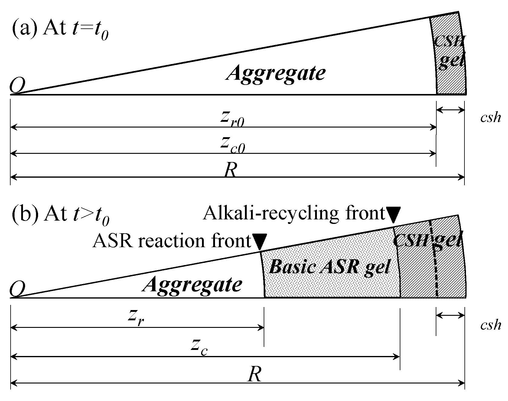
The following reaction sequence for the formation of ASR products is considered in our model. The reaction initiates from the dissolution of silica in an alkaline environment, in which the () bonds are attacked progressively by hydroxyl ions. The released silica is consumed very quickly by calcium in the nearby pore solution to form a C-S-H layer as shown in Figure 1a. This leads to the local depletion of calcium [1,33,34]. Then, the released silica will bind (or ) to form alkali silicates, which is called the basic ASR gel in this paper; see Figure 1b. Note that the imbibition of water is not considered yet in this basic gel. As the calcium in the pore solution penetrates into the gel layer, some of alkalis in the basic gel will be replaced by calcium to form C-S-H gel, which is called alkali-recycling by calcium [1]; see Figure 1b. Two reaction fronts are considered in our model; the ASR reaction front, , and the alkali recycling front, , respectively.
The gel is so hygroscopic that it imbibes nearby water to generate hydrated alkali silicate gel. This is the swelling of ASR gel. The expansive pressure induced by the swelling gel causes the deterioration of concrete. The water imbibition ability (or swelling capacity) of the basic gel is influenced by the chemical composition of the gel, for example, the concentration of calcium ions in the gel [23,24]. This dependence on calcium in the pore solution is considered in this model.
2.2. Formation of the Basic Gel
In the model proposed in Reference [5], the advance of the reaction front of ASR in a reactive aggregate was driven by water diffusion. A part of the reacted aggregate was modeled as the ASR gel [17,18]. This would result in the same volume of reacted aggregate regardless of the alkalinity. This means that the reactive aggregate may fully react without producing the ASR gel in an asymptotically extreme case, such as a very low alkaline environment. In this case, even if high alkaline environment is supplied later, no more reactive aggregate is left. In addition, alkali release from aggregates is not considered.
However, the dissolution rate of silica in reactive aggregates depends on the alkalinity of the solution [35]. The advance of the reaction front in the reactive aggregate would be better described by means of the alkali content in the pore solution, rather than the water [6,36]. It is better to consider the transport of alkali explicitly because alkali concentration may be influenced by internal alkali release from reactive aggregates, and external alkali supplies, too.
With a given reactive aggregate, the reaction between alkali and silica in the reactive aggregate is governed by the diffusion of alkali from the pore solution. To simplify the calculation of the advance of the reaction front, a steady state diffusion process of the alkali is assumed as in the literature [5,17,18]. Then the concentration of free alkali in the corresponding reacted layer, is given as
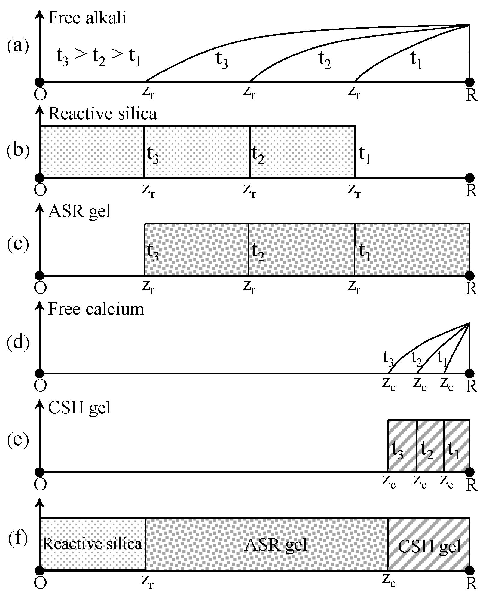
where is the concentration of free alkali in the pore solution (mol/ of pore solution), R is the radius of the reactive aggregate, and is the reaction front of ASR with initial value . The distribution of free alkali is shown in Figure 2a schematically.
By assuming the alkali released at the reaction front will be consumed instantly in situ, the mass balance of alkali at the reaction front will be given as
where is the alkali-to-silica stoichiometric mass conversion ratio, with the mass density of reactive inside the aggregate , and the molar weight of . with the mass of releasable alkali per volume of aggregate , mainly , and the molar weight of , is the diffusivity of alkali into the aggregate which depends on temperature and humidity as given in Appendix A. Note that the reactive silica is only a part of the total silica content and depends on the type of aggregates. The consumption of the reactive silica is shown in Figure 2b at different times schematically.
The movement speed of ASR reaction front can be determined by substituting , the free alkali Equation (1) into Equation (2)
The growth of the basic ASR gel is shown in Figure 2c.
The thickness of the C-S-H layer formed instantaneously by the reaction of the dissolved silica and calcium was determined as = 1.05 m following the method proposed by Reference [37]. This layer is not considered to imbibe water. The more the calcium is penetrated into the gel layer from the pore solution, the more the basic gel will be converted into C-S-H [1,33].
Similar to the movement of the ASR front, the alkali-recycling front can be determined by means of another Stefan condition, i.e.,
where is the concentration of calcium in the corresponding converted layer, is the concentration of calcium in the pore solution (mol/ of pore solution) as given in Appendix B, R is the radius of the reactive aggregate, is the convert front, is the calcium-to-alkali stoichiometric mass conversion ratio, with the mass density of reactive inside the aggregate , and the molar weight of . is the diffusivity of calcium into the aggregate which depends on temperature and humidity as given in Appendix A. The distribution of the free calcium is shown in Figure 2d. The growth of C-S-H gel by the alkali-recycling effect is shown in Figure 2e. The ASR gel and the C-S-H gel at time t is shown in Figure 2f.
Two different sources of alkalis are considered for the alkali bound in the gel layer; one is the alkali released from aggregates and the other the alkali supplied from the pore solution. Here, we assume both of them will be recycled by calcium.
The total volume and mass of the basic gel before the imbibition of water in an aggregate can be determined by the volume of the aggregate that has reacted.
where is the total volume of the basic gel before the imbibition of the water in an aggregate. is the total mass of the basic gel before the imbibition of the water in an aggregate.
2.3. Swelling of the Basic Gel
Swelling of the basic gel by water imbibition may be given by References [5,18].
where is the thermodynamic affinity of the water imbibition, which is the imbalance between the imbibed water at a thermodynamic equilibrium and the current imbibed water; is an empirical constant for water imbibition at the thermodynamic equilibrium; is the characteristic time of the water imbibition; is the distance to reach the gel in the water transport process which increases with the advance of the reaction front; and is the diffusivity of water for the micro-diffusion near the aggregate, which is a nonlinear function of temperature and the relative humidity that is given in Appendix A.
in Equation (10) represents the maximum amount of water imbibition by the basic gel. The maximum water imbibition must depend on the expansibility of the gel. This is strongly influenced by the chemical composition of the gel, specifically, the ratio of Na(K)/Si and Ca/Si, etc., in the gel [23,24]. As the concentration of Ca increases and that of Na(K) decreases, the gel will behave more like C-S-H gel [38]. In such a condition, the expansibility of the ASR product is low, or negligible. Therefore, the thermodynamic affinity of Equation (10) is corrected by the expansibility of the gel as given by
where is the expansibility of the gel depending on its chemical composition.
Because of the complicated nature of the alkali silica reaction, it is difficult to capture the exact composition of the gel at different positions even with numerical simulations. We adopt Multon and Sellier’s [20] proposal to estimate the expansibility of the gel, which is proportional the ratio of sodium to calcium in the pore solution. The expansibility of the gel is given by
where is the ratio of sodium to calcium in the pore solution, is the threshold value for the expansibility which depends on temperature. By referring to the experiment data [39], may be given by , with , , and kJ/mol. is equal to X if or equal to 0 if . is the ratio of sodium to calcium when the silica is most reactive, i.e., when the alkali charge-balanced by hydroxide ions is 1 mol/L as reported in Reference [35]. It is calculated based on the calcium concentration, which is temperature dependent, as given in Appendix B.
We consider sodium as alkali in this model. To calculate the ratio of sodium to calcium, both alkalis charge-balanced by hydroxide ions and charge-balanced by other anions, such as chloride ions, are considered. To simplify the calculation, the relative proportion of the alkali contents in the pore solution charge-balanced by different anions were assumed to keep the same proportion during the diffusion of alkalis because of the similarity of diffusion coefficients of the anions that charge-balanced with the alkalis [40,41]. Another reason of the simplification is the complexities for describing the multi-species ionic diffusion in the pore solution of concrete correctly [41,42], which is too complicated within the frame of this work.
3. Mass Transport at Macro-Scale
3.1. Transport of Alkali
Alkalis in the reactive aggregates are released gradually as the silica dissolves [1,43]. While the exact mechanism of the alkali release is not completely understood yet, it is believed that the release process mainly depends on the ion exchange reaction between sodium from siliceous aggregate and calcium from the pore solution [1,30]. The released amount is related to the volume of the reaction layer of the aggregate. Since the ASR reaction is much slower than hydration, it is assumed that all the alkalis in cement was released into the pore solution, for a simplification.
The total concentration of alkali per volume of concrete includes the free alkali in the pore solution, the alkali in the reactive aggregates, and the alkali bound in the ASR gel, i.e.,
where is the total alkali content in a unit volume of concrete (mol/ of concrete), is the volume fraction of evaporable pore water ( solution/ concrete), is the free alkali content in the pore solution (mol/ of pore solution), is the alkali content in the aggregate which will decrease due to its release (mol/ of concrete), and is the alkali content bound in the ASR gel (mol/ of concrete). The relation between and humidity (h) could be obtained according to the model developed by Brunauer, Skalny, and Bodor (BSB model) [44], given in Appendix A.
The alkali content in the aggregate, , will decrease due to release caused by dissolution. The alkali content bound in the ASR gel, , will increase due to the gel formation and decrease due to calcium recycling. It depends on the reaction front of ASR and alkali-recycling front as given in Equations (3) and (6). They are expressed as
where is the number of reactive aggregates per volume of concrete (1/ of concrete), which is calculated by dividing the total mass of the aggregates by the mass of the representative aggregate, , , and is the alkali-to-silica stoichiometric mass conversion ratio.
The momentary rate of the total alkali content can be calculated as
The alkali mass balance governing equation is given by
where is the diffusion coefficient of free alkali, which is a nonlinear function of temperature and relative humidity, as given in Appendix A.
By combining Equations (17) and (18), the alkali mass balance governing equation can be obtained and simplified as
where being the term representing the alkali released from aggregate, and being the sink term reflecting alkali fixed in the gel. The first term of means the alkali recycling rate by calcium and the second means the binding rate due to formation of the new basic gel.
3.2. Transport of Heat and Moisture
The moisture mass balance governing equation is given by
where is the moisture diffusion coefficient, which is a nonlinear function of temperature and the relative humidity that is given in Appendix A, is the amount of water consumed by the basic ASR gel, and is the amount of water imbibition. They are given by
where is the number of reactive aggregates per unit volume of concrete (1/ of concrete), and is the amount of water imbibition by the ASR gel in one aggregate (kg).
Without considering any internal sink or internal source term of heat, the heat transfer equation is given by
where T is the temperature (K), is the concrete mass density , and is the specific heat of concrete, ranging from 840 to 1170 [45], with an average value of 1100 taken in this paper. is the thermal conductivity of concrete, which is slightly dependent on temperature, moisture, and aging; an average value of 1.74 is taken in this paper.
4. ASR-Induced Volume Expansion
4.1. Expansion Pressure Caused by ASR
The swelling ASR gel due to water imbibition will first be accommodated by easily accessible pores around the aggregate without producing pressure [16]. Once the easily accessible pores are filled, further water imbibition will produce pressure. The infiltration of ASR gel will then take in place as a consequence [18]. The volume fraction of the space available to the ASR gel due to the infiltration of the gel can be calculated as
where , is the equivalent permeability for the volume infiltration; p is the pressure; the number of infiltration paths in the representative volume that can be assumed nevertheless; is the average cross section area of one infiltration path, and here the infiltration path is taken as capillary pores with diameter of 10 m [46]; and is the permeability for the gel movement depending on temperature given in Appendix A. is the volumetric strain, represents an empirical finite threshold, taken here as 0.01%, and exceeding this threshold will increase the permeability.
The total space fraction available for the ASR gel in one representative volume of concrete is given by
where is the volume fraction of the basic gel (/ of concrete), = , is the volume fraction of the interface transition zone (ITZ), and the thickness of ITZ is considered to be constant and independent of the aggregate size [16,20]. is the pore volume fraction surrounding the aggregate without producing any pressure (/ of concrete), taken here as 1.0E-5; is the volume fraction of the space available to the ASR gel by the infiltration (/ of concrete); and is the volume fraction produced by mechanical deformation. We set equal to the volumetric strain of concrete.
The volumetric strain of the ASR gel can be measured as
where is the total volume fraction of gel after imbibition ( of concrete), , and . is equal to X if or equal to 0 if .
Then, the volumetric stress of the gel is given as
where K is the bulk modulus of the ASR gel, which ranges between about 1.64 to 2.87 GPa for different alkali solutions, with an assumed Poisson ratio of 0.2 [47]. K can be even higher than 10 GPa for a gel containing high concentration of calcium [48]. In the present paper, it is set equal to that of water [18].
4.2. Damage of Concrete
In order to determine the ASR-induced free expansion in a simple way, a scalar isotropic damage model is used in the present paper at macro scale. The main advantage of using a scalar damage model is its simplicity when compared to more advanced models, including plasticity and anisotropy, etc. Mazars equivalent strain Reference [49] is adopted
For the standard isotropic damage model, the damage growth is governed by the damage loading function
where is the internal variable of the damage growth which is the maximum value of in the load history, and is the equivalent strain. The exponential damage evolution law on the form [50]
where and , with the tensile strength , E is Young’s modulus, and is fracture energy. Here, the crack band approach is adopted to keep mesh objectivity of the solution with the characteristic length .
By applying the ASR-induced expansive pressure, the constitute law can be written as:
with being the strain components, being the initial elastic modulus of the material, and p being the ASR-induced expansive pressure. being the Biot coefficient approximately equal to the porosity. However, the adsorbed water will behave like a load-bearing solid since the nanopores only a few atoms wide. Therefore, instead of Biot coefficient, the effective porosity is used, since it would be incorrect to use the same Biot coefficient as for saturated situation [18]. Furthermore, being the effective porosity which is defined as the area fraction of gel in a plane cross section of the material, with the pressurized volume fraction which is the total volume of gel, , and the empirical parameter, , representing the geometrical features of the infiltration paths [18].
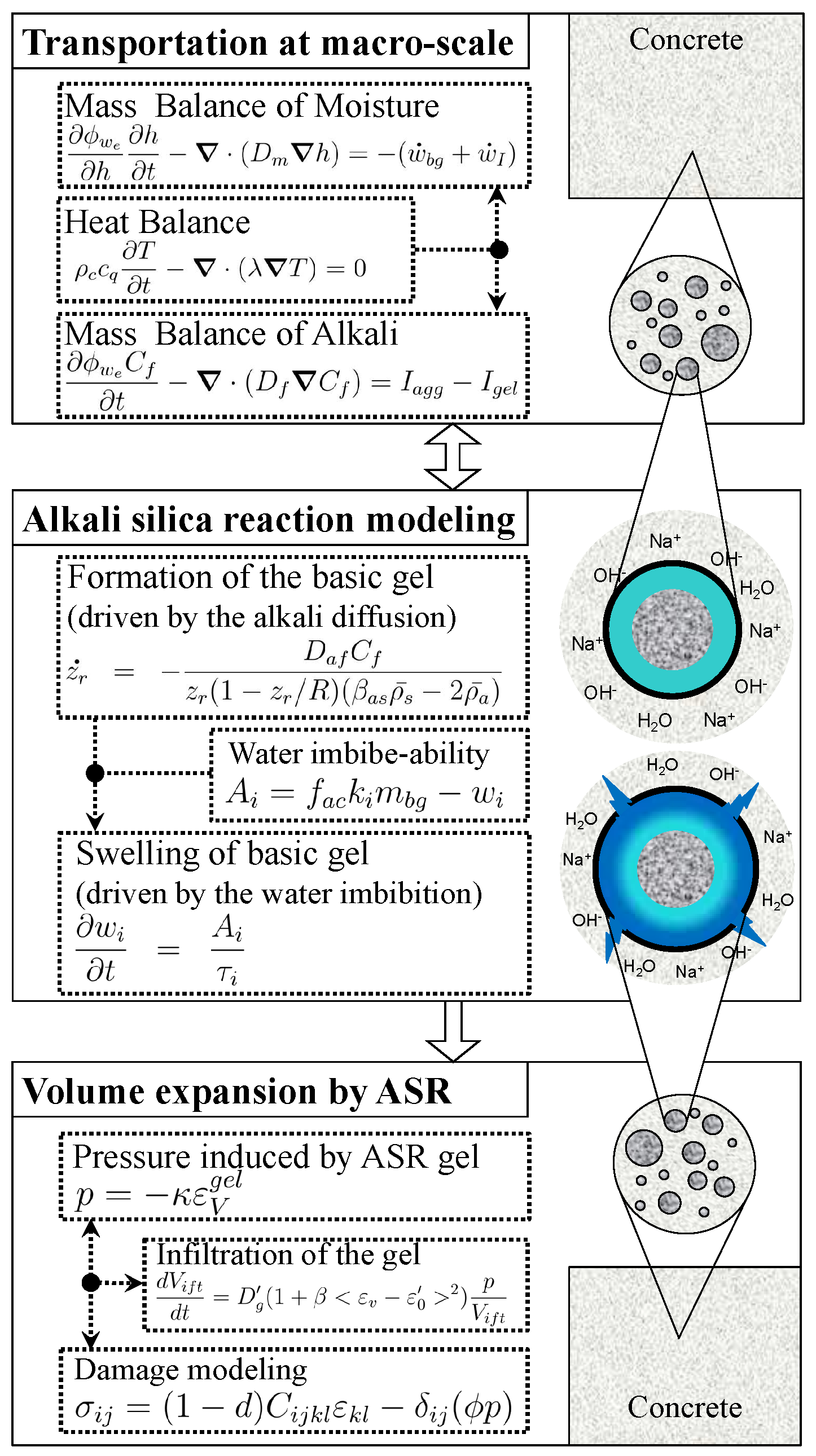
In summary, the developed model from chemical to mechanical are schematically described in Figure 3.
5. Summary of Model Parameters and Sensitivity Analysis
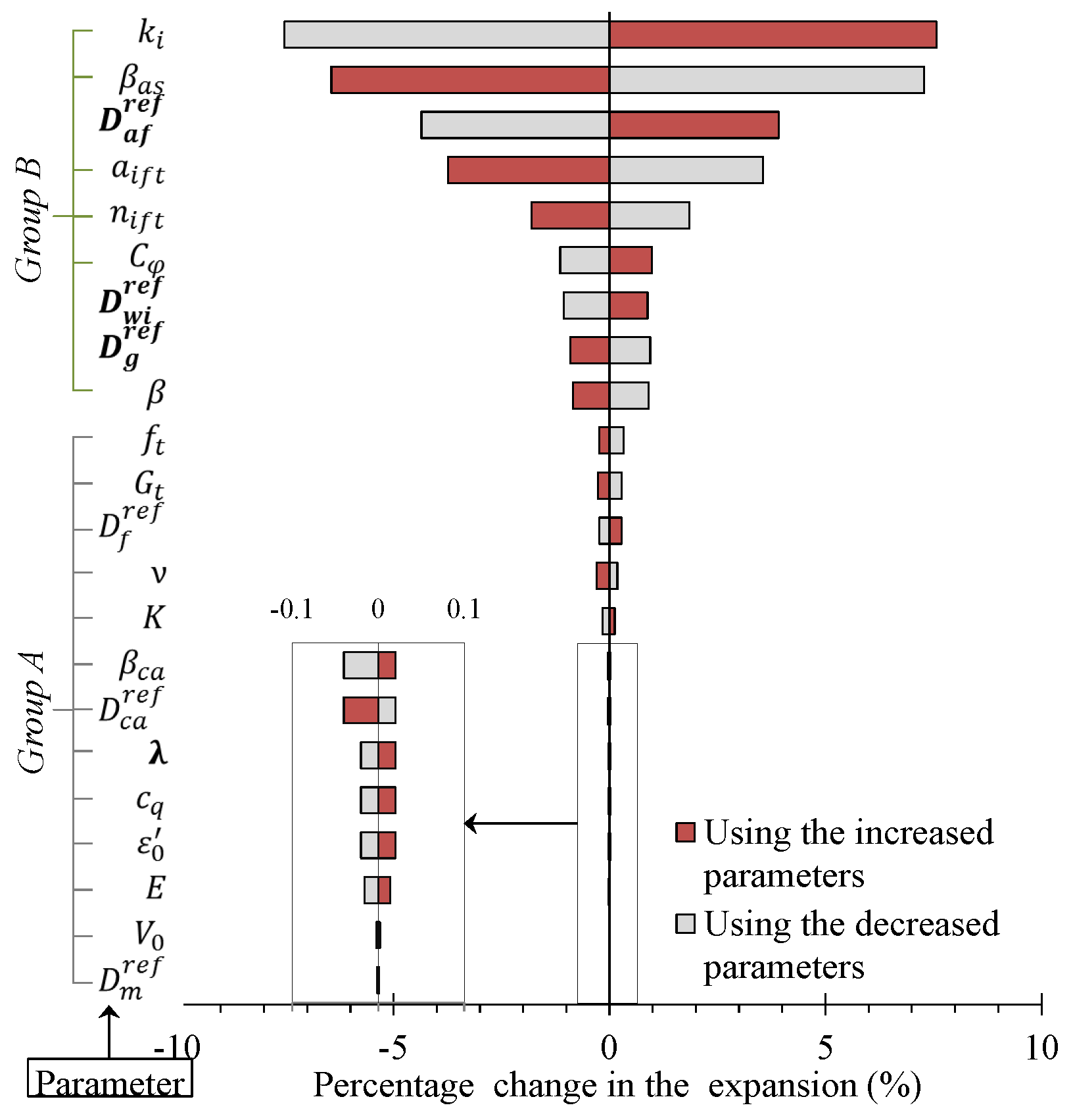
The reference input parameters are summarized in Table 1. In order to minimize the number of model parameters, a sensitivity analysis was carried out. The one-way sensitivity analysis was adopted for the simplicity. The verification example at Section 6.1 is for the effect of temperature on ASR expansion. It has all the key features of the developed model, such as formation of basic gel driven by alkali ions, swelling of basic gel driven by water imbibition, infiltration of gel, etc. All the model parameters play a role in this example. Therefore it is suitable for sensitivity analysis. By taking the expansion at 38 C as a reference, the influence of each parameter was investigated as shown in Figure 4. Each parameter was changed by 10%.
According to the sensitivity analysis, the parameters can be grouped into two sets as shown in Figure 4. Because the influence of group A is marginal, parameters belonging to group A may be fixed for any of furthers simulations. Group B are significant parameters. Among them, , , , and can be determined independently from the mix proportion and the chemical information in advance before analysis. and can be determined separately, too, by referring to the literature information [51]. Therefore, there are only three parameters, i.e., , , and , to be calibrated in the following verification examples.
6. Verification Examples
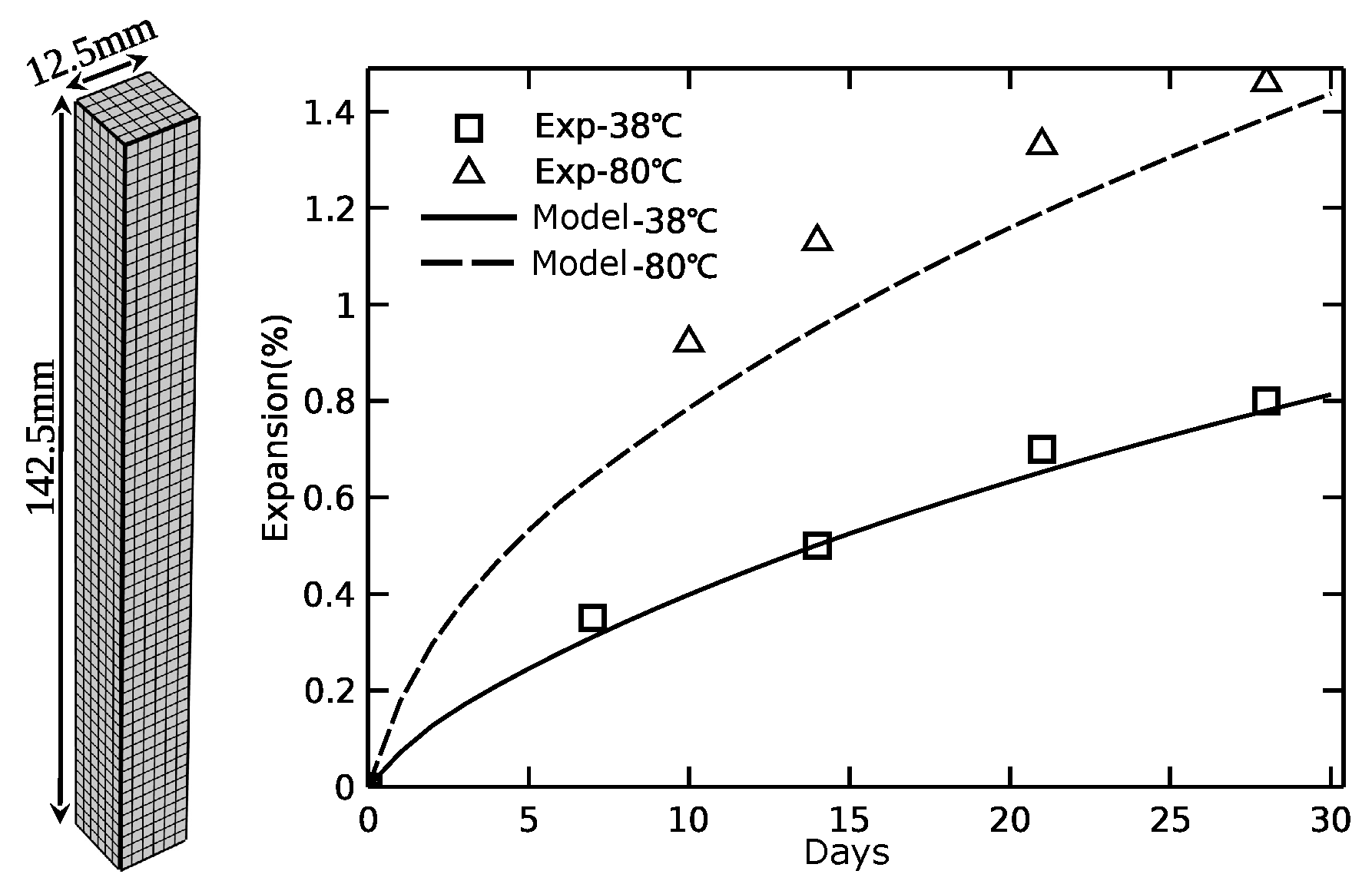
6.1. Effect of Temperature on ASR
The effect of temperature on ASR was investigated experimentally by Desai [52]. In the experiment, specimens with size 25 mm × 25 mm × 285 mm were casted with fused silica as the reactive aggregate. The incorporated aggregate size was 0.15–4.75 mm as for standard ASTM C-1260. The specimens were immersed in 1N NaOH solution with temperatures of 38 C and 80 C. The results showed that the expansion was higher with increased temperature, as shown in Figure 5.
In the model, two size groups of aggregates were incorporated for simplification, diameter with 0.4 and 2.2 mm, respectively. Thanks to the symmetry, only one 1/8 of specimen had to be simulated, as shown in Figure 5 on the left. Linear brick elements were used both for diffusion and mechanics. The size of the elements is chosen as 2.5 mm, which was close to the size of the maximum aggregates. The parameters were calibrated based on the expansion curve at 38 C and are listed in Table 2. Then, the case of 80 C was simulated with the same set parameters, the results of which were shown in Figure 5. As shown in the figure, the effect of temperature on expansion was well captured by the model.
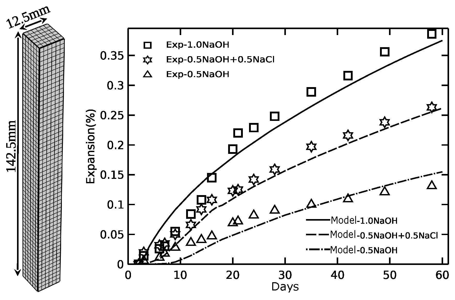
6.2. Effect of External Alkali on ASR
An experiment to investigate the characteristic of ASR in different alkali exposure environments was carried out recently [22]. Two size groups of waste glass were incorporated as the reactive aggregates in the specimens, group 1.18–2.36 mm and 2.36–4.75 mm, respectively. The specimens were immersed in three kinds of solution, 1N NaOH solution, 0.5N NaOH solution, and 0.5N NaOH+0.5N NaCl solution at 80 C. As shown in Figure 6, the expansion caused by ASR increases with the NaOH concentration of the solution. The expansion was increased significantly due to the addition of NaCl in the NaOH solution.
Numerical simulations were carried out with the developed model to capture the experimental results. The two size groups of aggregate were equivalently simplified in the model, diameter with 1.77 mm for group 1.18–2.36 mm and 3.56 mm for group 2.36–4.75 mm, respectively. Only 1/8 of specimen had to be modeled, as shown in Figure 6 on the left. The parameters used in the numerical model were calibrated based on the highest expansion curve at 1N NaOH, and are given in Table 2. Then, the other alkali contents were simulated with the same parameters, and the results are shown in Figure 6, along with the experimental expansion data.
The results indicate that the model can capture the influence of different alkali contents on expansion, except for a small gap in the early period. The expansion increased by NaCl with changes in the swelling capacity of gel was predicted very well. However, it may be noted that we ignored the change of hydroxide ions due to the formation of Friedel’s salt, etc.
6.3. Effect of Aggregate Size on ASR
Ramyar et al. [53] carried out an experiment according to ASTM C-1260 to investigate the effect of aggregate size on ASR. The experiment results are shown in Figure 7. It can be seen that the expansions caused by the largest and smallest aggregate groups (0.125–0.25 mm and 2.0–4.0 mm, respectively) are close to each other and lower than that of the other three groups. The expansion caused by group 0.25–0.5 mm was the highest. The overall trend is that the expansion caused by ASR increased first as the aggregate size decreased. It then showed the opposite trend as the size became smaller than 0.25–0.5 mm.
The parameters used in the numerical model were calibrated using the largest size aggregate group, as given in Table 2. Then, the other size groups were simulated with the same set of parameters. One eighth of the specimen was modeled as shown in Figure 7 on the left. As shown in Figure 7, the pessimum effect of the aggregate size was well reproduced by the model with a single set of parameters. As the aggregate size decreases, the expansion increases first following the decreases, and the maximum expansion occurs in the size group of 0.25–0.5 mm.
The smaller the aggregate is, the more the number of aggregate is in the unit volume of specimen for the specimen contains same amount of reactive aggregate. On the one hand, this means more pores that accommodate the gel without expansion is available in the unit volume of specimen. This includes the volume of ITZ pores and the volume of the space available by the infiltration of gel, etc. As a result, the smaller the aggregate is, the smaller the expansion is caused by ASR. On the other hand, the more the number of smaller aggregate in the unit volume of specimen, the more ASR gel will be produced due to the higher specific surface area. As a result, the smaller the aggregate is, the bigger the expansion is caused by ASR. These two competing aspects explained the pessimum effect of the aggregate size as shown above.
6.4. Verification the Effect of Alkali Released from Aggregate on ASR
Instead of immersing the specimens in alkali solution, the alkali released from aggregate will play an important role when the specimens were immersed in water, or when the experiment was carried out in 100% humidity environment [30].
In the experiment carried out by Ben Haha [54], mortar bars (40 mm × 40 mm × 160 mm were stored at three temperatures (20, 40, and 60 C), along with a small amount of water in order to maintain 100% humidity and limit alkali leaching. The reactive aggregate contains alkali was used to prepare the specimens, with size groups of 0–3 mm.
In the model, two sizes of aggregates were incorporated for simplicity. Eight-five percent with the size of 2 mm and 15% with the size of 0.75 mm, as suggested in Reference [51]. The results of XRD showed that the principle phases of the aggregates were quartz and illite. Illite contains up to 7.26 percent alkali (), which will be released into the pore solution as the reaction proceeds. The mass ratio of alkali in aggregate depends on their chemical composition. This could range from 0.01% for limestone to 14% for soda-lime glass aggregates. Since the exact amounts of illite and alkali in the aggregates were unknown, we assume here that the alkali content in aggregate was 1.0%. The parameters adopted in the model are listed in Table 2. One eighth of specimen was modeled with linear brick elements, as shown in Figure 8 on the left.
Good agreement can be seen in Figure 8, while, for the case of low temperature, there was some discrepancy between the simulation results and the experimental results.
7. Conclusions
A model is proposed for the expansion and damage caused by ASR where the ASR reaction and expansion are modeled separately. The ASR reaction is modeled by the diffusion of alkali. The expansion is modeled by the water imbibition to the gel. The model can be calibrated by means of only three parameters on the diffusion of alkali and water in the representative microstructure. Other parameters can be determined from the mix proportion and the literature, independently.
Different sources of alkalis are considered in the model, including external alkali, internal alkali released from aggregates, and alkali of the ASR gel recycled by calcium. The effect of alkali released from aggregate on ASR is considered at both aggregate and concrete scale.
The volume of the expansive ASR gel is the consequence of the ASR reaction and the calcium recycling. The ASR reaction increases the volume of the expansive gel, while the calcium recycling decreases the volume of the gel. The expansibility of the ASR gel is calculated by the sodium to calcium ratio in the pore solution and temperature.
To verify the developed model, the numerical results were compared with several sets of experimental data. The influence of temperature, external alkali, and aggregate size effect are well captured.
The developed model is more in line with the reaction sequence for the formation of ASR products. However, the mechanics model used in the model is a simple damage model without considering creep, plastic deformation, etc. A more sophisticated mechanics model is required, and this is our ongoing research.
Author Contributions
Conceptualization, L.S. and G.Z.; software, L.S. and X.Z. (Xingji Zhu); writing—original draft preparation, L.S.; writing—review and editing, G.Z., X.Z. (Xingji Zhu) and X.Z. (Xiaoying Zhuang); Supervision, G.Z. All authors have read and agreed to the published version of the manuscript.
Funding
This research was supported by a grant (20CTAP-C152291-02) from Technology Advancement Research Program funded by Ministry of Land, Infrastructure and Transport of Korean government. The first author would like to acknowledge the support of the China Scholarship Council (CSC201606450022).
Conflicts of Interest
The authors declare no conflict of interest. The funders had no role in the design of the study; in the collection, analyses, or interpretation of data; in the writing of the manuscript, or in the decision to publish the results.
Appendix A. Volume Fraction of Evaporable Pore Water and Diffusion Coefficients
The relation between volume fraction of evaporable pore water and humidity h can be estimated as:
where C, , and are parameters. For days and , they can be determined as [55]
where is the age of concrete hydration in days. The unit of temperature is K.
with the reference values at reference temperature: , , , , , and the influence of temperature and humidity:
where is the reference temperature, T is the current temperature, R is the universal gas constant, and U = , , , and are the activation energies of the alkali diffusion process, calcium diffusion process, moisture diffusion process, and gel infiltration process, respectively. = 20 kJ/mol for aggregate, 40 kJ/mol for cement paste [20], = 44 kJ/mol, = 42.5 kJ/mol, = 45 kJ/mol [18], and the value of is between 0.025 and 0.1, representing the ratio of min and max . Here, we take = 0.05.
Appendix B. Concentration of Calcium in the Pore Solution
The molar concentration of calcium varies with concentrations of alkali (charge-balanced by hydroxyl ions) and temperature. The relation of the concentration of calcium in different concentration of alkali solution can be obtained based on the experimental data [56], as shown in Figure A1.
where (1 mol/L) is the dimensionless molar concentration of calcium ions, (1 mol/L) is the dimensionless molar concentration of alkali, a, b and c are temperature-dependent parameters, a = + , b = , and c = − , with (1 K), the dimensionless temperature.
Figure A1.
calculated at different temperatures compare with experimental data [56].
Figure A1.
calculated at different temperatures compare with experimental data [56].

References
- Rajabipour, F.; Giannini, E.; Dunant, C.; Ideker, J.H.; Thomas, M.D. Alkali–silica reaction: Current understanding of the reaction mechanisms and the knowledge gaps. Cem. Concr. Res. 2015, 76, 130–146. [Google Scholar] [CrossRef]
- Ichikawa, T.; Miura, M. Modified model of alkali-silica reaction. Cem. Concr. Res. 2007, 37, 1291–1297. [Google Scholar] [CrossRef]
- Pan, J.; Feng, Y.; Wang, J.; Sun, Q.; Zhang, C.; Owen, D. Modeling of alkali-silica reaction in concrete: A review. Front. Struct. Civ. Eng. 2012, 6, 1–18. [Google Scholar] [CrossRef]
- Esposito, R.; Hendriks, M. Literature review of modelling approaches for ASR in concrete: A new perspective. Eur. J. Environ. Civ. Eng. 2017, 23, 1311–1331. [Google Scholar] [CrossRef] [Green Version]
- Bažant, Z.P.; Steffens, A. Mathematical model for kinetics of alkali–silica reaction in concrete. Cem. Concr. Res. 2000, 30, 419–428. [Google Scholar] [CrossRef] [Green Version]
- Suwito, A.; Jin, W.; Xi, Y.; Meyer, C. A mathematical model for the pessimum size effect of ASR in concrete. Concr. Sci. Eng. 2002, 4, 23–34. [Google Scholar]
- Comby-Peyrot, I.; Bernard, F.; Bouchard, P.O.; Bay, F.; Garcia-Diaz, E. Development and validation of a 3D computational tool to describe concrete behaviour at mesoscale. Application to the alkali-silica reaction. Comput. Mater. Sci. 2009, 46, 1163–1177. [Google Scholar] [CrossRef]
- Dunant, C.F.; Scrivener, K.L. Micro-mechanical modelling of alkali–silica-reaction-induced degradation using the AMIE framework. Cem. Concr. Res. 2010, 40, 517–525. [Google Scholar] [CrossRef]
- Giorla, A.B.; Scrivener, K.L.; Dunant, C.F. Influence of visco-elasticity on the stress development induced by alkali—Silica reaction. Cem. Concr. Res. 2015, 70, 1–8. [Google Scholar] [CrossRef]
- Charpin, L.; Ehrlacher, A. Microporomechanics study of anisotropy of ASR under loading. Cem. Concr. Res. 2014, 63, 143–157. [Google Scholar] [CrossRef]
- Ulm, F.J.; Coussy, O.; Kefei, L.; Larive, C. Thermo-chemo-mechanics of ASR expansion in concrete structures. J. Eng. Mech. 2000, 126, 233–242. [Google Scholar] [CrossRef]
- Saouma, V.; Perotti, L. Constitutive model for alkali-aggregate reactions. ACI Mater. J. 2006, 103, 194. [Google Scholar]
- Capra, B.; Sellier, A. Orthotropic modelling of alkali-aggregate reaction in concrete structures: numerical simulations. Mech. Mater. 2003, 35, 817–830. [Google Scholar] [CrossRef]
- Farage, M.; Alves, J.; Fairbairn, E. Macroscopic model of concrete subjected to alkali–aggregate reaction. Cem. Concr. Res. 2004, 34, 495–505. [Google Scholar] [CrossRef]
- Morenon, P.; Multon, S.; Sellier, A.; Grimal, E.; Hamon, F.; Bourdarot, E. Impact of stresses and restraints on ASR expansion. Constr. Build. Mater. 2017, 140, 58–74. [Google Scholar] [CrossRef] [Green Version]
- Bažant, Z.P.; Zi, G.; Meyer, C. Fracture mechanics of ASR in concretes with waste glass particles of different sizes. J. Eng. Mech. 2000, 126, 226–232. [Google Scholar] [CrossRef] [Green Version]
- Alnaggar, M.; Cusatis, G.; Di Luzio, G. Lattice discrete particle modeling (LDPM) of alkali silica reaction (ASR) deterioration of concrete structures. Cem. Concr. Compos. 2013, 41, 45–59. [Google Scholar] [CrossRef]
- Bažant, Z.P.; Rahimi-Aghdam, S. Diffusion-controlled and creep-mitigated ASR damage via microplane model. I: Mass concrete. J. Eng. Mech. 2016, 143, 04016108. [Google Scholar] [CrossRef]
- Multon, S.; Sellier, A.; Cyr, M. Chemo–mechanical modeling for prediction of alkali silica reaction (ASR) expansion. Cem. Concr. Res. 2009, 39, 490–500. [Google Scholar] [CrossRef] [Green Version]
- Multon, S.; Sellier, A. Multi-scale analysis of alkali–silica reaction (ASR): impact of alkali leaching on scale effects affecting expansion tests. Cem. Concr. Res. 2016, 81, 122–133. [Google Scholar] [CrossRef] [Green Version]
- Kawamura, M.; Takeuchi, K.; Sugiyama, A. Mechanisms of expansion of mortars containing reactive aggregate in NaCl solution. Cem. Concr. Res. 1994, 24, 621–632. [Google Scholar] [CrossRef]
- Shim, W. Characteristics of Alkali-Silica Reaction in Differing Externally Supplied Alkali Exposure Environment. Master’s Thesis, Korea University, Seoul, Korea, 2019. [Google Scholar]
- Gholizadeh-Vayghan, A.; Rajabipour, F. Quantifying the swelling properties of alkali-silica reaction (ASR) gels as a function of their composition. J. Am. Ceram. Soc. 2017, 100, 3801–3818. [Google Scholar] [CrossRef]
- Vayghan, A.G. Characterization of the Rheological and Swelling Properties of Synthetic Alkali Silicate Gels in Order to Predict Their Behavior in ASR Damaged Concrete; Pennsylvania State University: State College, PA, USA, 2017. [Google Scholar]
- Drolet, C.; Duchesne, J.; Fournier, B. Validation of the alkali contribution by aggregates to the concrete pore solution. Cem. Concr. Res. 2017, 98, 10–23. [Google Scholar] [CrossRef]
- Constantiner, D.; Diamond, S. Alkali release from feldspars into pore solutions. Cem. Concr. Res. 2003, 33, 549–554. [Google Scholar] [CrossRef]
- Berra, M.; Costa, U.; Mangialardi, T.; Paolini, A.E. Application of an innovative methodology to assessing the alkali-silica reaction in concrete. Mater. Struct. 2015, 48, 2727–2740. [Google Scholar] [CrossRef]
- Canadian Electrical Association; Pigeon, M.; Tecsult Inc.; Stoian, A. Expansion Test Methods for Mass Concrete Exposed to Alkali Aggregate Reaction; Canadian Electrical Association: Ottawa, ON, Canada, 1992. [Google Scholar]
- Grattan-Bellew, P. Laboratory evaluation of alkali-silica reaction in concrete from Saunders Generating Station. Mater. J. 1995, 92, 126–134. [Google Scholar]
- Yujiang, W.; Min, D.; Mingshu, T. Alkali release from aggregate and the effect on AAR expansion. Mater. Struct. 2008, 41, 159. [Google Scholar] [CrossRef]
- Yu, P.; Duan, Y.; Chen, E.; Tang, S.; Hanif, A.; Fan, Y. Microstructure-based homogenization method for early-age creep of cement paste. Constr. Build. Mater. 2018, 188, 1193–1206. [Google Scholar] [CrossRef]
- Zhou, W.; Duan, L.; Tang, S.; Chen, E.; Hanif, A. Modeling the evolved microstructure of cement pastes governed by diffusion through barrier shells of C–S–H. J. Mater. Sci. 2019, 54, 4680–4700. [Google Scholar] [CrossRef]
- Hou, X.; Struble, L.J.; Kirkpatrick, R.J. Formation of ASR gel and the roles of CSH and portlandite. Cem. Concr. Res. 2004, 34, 1683–1696. [Google Scholar] [CrossRef]
- Idir, R.; Cyr, M.; Tagnit-Hamou, A. Pozzolanic properties of fine and coarse color-mixed glass cullet. Cem. Concr. Compos. 2011, 33, 19–29. [Google Scholar] [CrossRef]
- Maraghechi, H.; Rajabipour, F.; Pantano, C.G.; Burgos, W.D. Effect of calcium on dissolution and precipitation reactions of amorphous silica at high alkalinity. Cem. Concr. Res. 2016, 87, 1–13. [Google Scholar] [CrossRef] [Green Version]
- Puatatsananon, W.; Saouma, V. Chemo-Mechanical Micromodel for Alkali-Silica Reaction. ACI Mater. J. 2013, 110, 67. [Google Scholar]
- Moon, J.; Taha, M.; Youm, K.S.; Kim, J. Investigation of pozzolanic reaction in nanosilica-cement blended pastes based on solid-state kinetic models and 29Si MAS NMR. Materials 2016, 9, 99. [Google Scholar] [CrossRef] [Green Version]
- You, I.; Zi, G.; Yoo, D.; Lange, D.A. Durability of concrete containing LCD glass powder for pavement. ACI Mater. J. 2019, in press. [Google Scholar] [CrossRef]
- Kim, T.; Olek, J.; Jeong, H. Alkali–silica reaction: kinetics of chemistry of pore solution and calcium hydroxide content in cementitious system. Cem. Concr. Res. 2015, 71, 36–45. [Google Scholar] [CrossRef]
- Samson, E.; Marchand, J.; Snyder, K.A. Calculation of ionic diffusion coefficients on the basis of migration test results. Mater. Struct. 2003, 36, 156–165. [Google Scholar] [CrossRef]
- Johannesson, B.; Yamada, K.; Nilsson, L.O.; Hosokawa, Y. Multi-species ionic diffusion in concrete with account to interaction between ions in the pore solution and the cement hydrates. Mater. Struct. 2007, 40, 651. [Google Scholar] [CrossRef]
- Guo, B.; Hong, Y.; Qiao, G.; Ou, J. A COMSOL-PHREEQC interface for modeling the multi-species transport of saturated cement-based materials. Constr. Build. Mater. 2018, 187, 839–853. [Google Scholar] [CrossRef]
- Shafaatian, S. Innovative Methods to Mitigate Alkali-Silica Reaction in Concrete Materials Containing Recycled Glass Aggregates. Ph.D. Thesis, Pennsylvania State University, University Park, State College, PA, USA, 2012. [Google Scholar]
- Brunauer, S.; Skalny, J.; Bodor, E. Adsorption on nonporous solids. J. Colloid Interface Sci. 1969, 30, 546–552. [Google Scholar] [CrossRef]
- Neville, A.M. Properties of Concrete; Longman: London, UK, 1995. [Google Scholar]
- Mindess, S.; Young, F.; Darwin, D. Concrete, 2nd ed.; Prentice Hall: Upper Saddle River, NJ, USA, 2003. [Google Scholar]
- Liu, K.W.; Baranikumar, A.; Grasley, Z.; Mukhopadhyay, A.K. Mechanical Properties of Alkali-Silica Reaction Gel Measured by Nanoindenter. Am. J. Eng. Technol. Soc. 2015, 2, 121–124. [Google Scholar]
- Phair, J.W.; Tkachev, S.N.; Manghnani, M.H.; Livingston, R.A. Elastic and structural properties of alkaline-calcium silica hydrogels. J. Mater. Res. 2005, 20, 344–349. [Google Scholar] [CrossRef]
- Mazars, J. A description of micro-and macroscale damage of concrete structures. Eng. Fract. Mech. 1986, 25, 729–737. [Google Scholar] [CrossRef]
- Oliver, J.; Cervera, M.; Oller, S.; Lubliner, J. Isotropic damage models and smeared crack analysis of concrete. In Proceedings of the International Conference on Computer Aided Analysis and Design of Concrete Structures (SCI-C’90), Zell am See, Austria, 4–6 April 1990; pp. 945–958. [Google Scholar]
- Rahimi-Aghdam, S.; Bažant, Z.P.; Caner, F.C. Diffusion-controlled and creep-mitigated ASR damage via microplane model. II: material degradation, drying, and verification. J. Eng. Mech. 2016, 143, 04016109. [Google Scholar] [CrossRef] [Green Version]
- Desai, P. Alkali Silica Reaction under the Influence of Chloride Based Deicers. Master’s Thesis, The Graduate School of Clemson University, Pickens County, SC, USA, 2010. [Google Scholar]
- Ramyar, K.; Topal, A.; Andiç, Ö. Effects of aggregate size and angularity on alkali–silica reaction. Cem. Concr. Res. 2005, 35, 2165–2169. [Google Scholar] [CrossRef]
- Haha, M.B. Mechanical Effects of Alkali Silica Reaction in Concrete Studied by SEM-Image Analysis. Ph.D. Thesis, EPFL, Lausanne, Switzerland, 5 May 2006. [Google Scholar]
- Xi, Y.; Bažant, Z.P.; Jennings, H.M. Moisture diffusion in cementitious materials adsorption isotherms. Adv. Cem. Based Mater. 1994, 1, 248–257. [Google Scholar] [CrossRef]
- Kutus, B.; Gácsi, A.; Pallagi, A.; Pálinkó, I.; Peintler, G.; Sipos, P. A comprehensive study on the dominant formation of the dissolved Ca(OH)2(aq) in strongly alkaline solutions saturated by Ca(II). RSC Adv. 2016, 6, 45231–45240. [Google Scholar] [CrossRef]
Figure 1.
Reaction front of alkali silica reaction (ASR) and alkali-recycling front in a representative reactive aggregate.
Figure 1.
Reaction front of alkali silica reaction (ASR) and alkali-recycling front in a representative reactive aggregate.

Figure 2.
Schematic description of the progress of phases distribution; (a) free alkali, (b) reactive silica, (c) basic ASR gel (or ASR reaction front), (d) free calcium, (e) C-S-H gel by alkali-recycling, and (f) distribution of different phases at time t.
Figure 2.
Schematic description of the progress of phases distribution; (a) free alkali, (b) reactive silica, (c) basic ASR gel (or ASR reaction front), (d) free calcium, (e) C-S-H gel by alkali-recycling, and (f) distribution of different phases at time t.

Figure 3.
Schematic description of the proposed model.

Figure 4.
Sensitivity of parameters on the ASR expansion.

Figure 5.
Comparison between measured [52] and simulated ASR expansions, effect of temperature.
Figure 5.
Comparison between measured [52] and simulated ASR expansions, effect of temperature.

Figure 6.
Comparison between measured [22] and simulated ASR expansions, effect of different alkali contents.
Figure 6.
Comparison between measured [22] and simulated ASR expansions, effect of different alkali contents.

Figure 7.
Comparison between measured [53] and simulated ASR expansions, fine aggregate.
Figure 7.
Comparison between measured [53] and simulated ASR expansions, fine aggregate.

Figure 8.
Comparison between measured [54] and simulated ASR expansions, mortar bars.
Figure 8.
Comparison between measured [54] and simulated ASR expansions, mortar bars.


Table 1.
Summary of the reference input parameters for the sensitivity analysis.
| Parameter | Value | Parameter | Value |
|---|---|---|---|
| * | 0.47 | 0.22 | |
| * | 2.25 | 2 | |
| 1.0 × 10 | 0.0001 | ||
| 3.0 × 10 | 4.5 × 10 | ||
| 8.3 × 10 | 0.00001 | ||
| 2.0 × 10 | K | 2.15 × 10 | |
| 1.1 × 10 | 1000 | ||
| 1.0 × 10 | 1.74 | ||
| 0.5 | E | 2.5 × 10 | |
| 0.5 | 0.2 | ||
| 25 m | 2.0 × 10 | ||
| 1 | 120 |
* Determined from the mix proportion before simulation.
Table 2.
Parameters used for the numerical simulations in this study.
| Set | Shim [22] | Desai [52] | Ramyar [53] | Ben Haha [54] |
|---|---|---|---|---|
| * | 0.47 | 0.47 | 0.47 | 0.51 |
| * | 2.25 | 2.25 | 2.25 | 3.0 |
| () | 3.7 × 10 | 8.3 × 10 | 3.7 × 10 | 5.2 × 10 |
| () | 4.0 × 10 | 2.0 × 10 | 2.0 × 10 | 4.0 × 10 |
| () | 2.9 × 10 | 1.1 × 10 | 2.9 × 10 | 2.9 × 10 |
* Determined from the mix proportion before simulation.
© 2020 by the authors. Licensee MDPI, Basel, Switzerland. This article is an open access article distributed under the terms and conditions of the Creative Commons Attribution (CC BY) license (http://creativecommons.org/licenses/by/4.0/).
Share and Cite
MDPI and ACS Style
Sun, L.; Zhu, X.; Zhuang, X.; Zi, G. Chemo-Mechanical Model for the Expansion of Concrete Due to Alkali Silica Reaction. Appl. Sci. 2020, 10, 3807. https://doi.org/10.3390/app10113807
AMA Style
Sun L, Zhu X, Zhuang X, Zi G. Chemo-Mechanical Model for the Expansion of Concrete Due to Alkali Silica Reaction. Applied Sciences. 2020; 10(11):3807. https://doi.org/10.3390/app10113807
Chicago/Turabian StyleSun, Lianfang, Xingji Zhu, Xiaoying Zhuang, and Goangseup Zi. 2020. "Chemo-Mechanical Model for the Expansion of Concrete Due to Alkali Silica Reaction" Applied Sciences 10, no. 11: 3807. https://doi.org/10.3390/app10113807
Note that from the first issue of 2016, this journal uses article numbers instead of page numbers. See further details here.