Article

Kinematic Conceptual Design of In-Line Four-Cylinder Variable Compression Ratio Engine Mechanisms Considering Vertical Second Harmonic Acceleration

1
Graduate School, Department of Mechanical Engineering, Korea University, Seoul 02841, Korea
2
School of Mechanical Engineering, Korea University, Seoul 02841, Korea
*
Author to whom correspondence should be addressed.
Appl. Sci. 2020, 10(11), 3765; https://doi.org/10.3390/app10113765
Submission received: 19 April 2020 / Revised: 18 May 2020 / Accepted: 27 May 2020 / Published: 29 May 2020
(This article belongs to the Section Mechanical Engineering)

Abstract

:
In the in-line four-cylinder engine, it is well known that the shaking force is due to the vertical second harmonic acceleration components of the pistons. This paper proposes a kinematic conceptual design method to determine the kinematic structure of a feasible in-line four-cylinder variable compression ratio (VCR) engine and its dimensions that would yield a lower vertical second harmonic acceleration at joints. Through type and dimensional synthesis, candidate VCR engine mechanisms are chosen and their dimensions satisfying design specifications are determined. Based on the analysis of the vertical second harmonic acceleration components at the joints, a feasible mechanism for an in-line four-cylinder VCR engine is selected. Then, the method finds the dimensions that yield a nearly minimized sum of the vertical second harmonic acceleration at each joint by adjusting the link lengths within specified tolerances. For validation, the result is compared with that of a constrained optimization using MATLAB. The proposed method would be useful at the conceptual design stage of multi-link multi-cylinder VCR and variable-stroke engine mechanisms where the second harmonic acceleration is an important design factor in the automotive industrial applications.

1. Introduction

The general performance and thermal efficiency of the internal combustion engine have been improved by various technologies such as turbochargers, fuel injection systems, and variable valve actuation systems [1]. In addition to the above, the variable compression ratio (VCR) engine technology has been considered as a method for improving fuel efficiency and reducing pollutants [2,3,4,5]. Various approaches have been suggested for the variation of the compression ratio, which include moving the crankshaft axis or the cylinder head, varying the combustion chamber volume or the piston deck height, and modifying the connecting rod geometry [6,7,8,9,10]. Numerous VCR engine mechanisms have been proposed [11,12,13], and their kinematic structures have been identified [14].
In general, as the VCR engine mechanism has more links than the conventional fixed compression ratio engine, the design of a VCR engine mechanism could be a quite complicated problem: the kinematic structure and dimensions of the mechanism that fits within the internal space of the engine must be determined, and then the dynamic characteristics and the balancing of shaking force and shaking moment need to be considered. The latter problem on the balancing of the conventional engine has been studied extensively [15,16,17]. The vertical second harmonic acceleration components of the pistons cause the shaking moments in the in-line three-cylinder, in-line five-cylinder, and V six-cylinder engines; the shaking forces in the in-line four-cylinder engine. In order to balance the shaking forces, an extra device, such as a balancer, which rotates at double engine speed, is used to balance the shaking force [18,19]. From this point of view, even though the complete dynamic analysis of a VCR engine under development is not possible until the mass properties of the parts are determined, considering the vertical second harmonic acceleration components would provide a good starting point at the conceptual design stage of a new VCR engine mechanism.
In the case of the fixed compression ratio engine, the crank can be shortened to decrease the magnitude of the second harmonic acceleration of the piston, but shortening the crank length causes a change in the stroke. For the VCR engine mechanism, since more links can be used to connect the piston and the crank, the second harmonic acceleration can be reduced by adjusting the link lengths without scarifying a desired stroke and top dead center (TDC) position.
In this paper, a kinematic conceptual design process of in-line four-cylinder VCR engine mechanisms considering the vertical second harmonic acceleration component at each joint is proposed. The proposed method includes the type and dimensional synthesis of candidate VCR engine mechanisms, harmonic acceleration analysis, selection of a feasible mechanism, and the minimization of the vertical second harmonic acceleration sum in the selected mechanism. For the type synthesis, the atlas of kinematic chains is used to choose appropriate candidates. The displacement equations of candidate mechanisms are derived and used to determine the initial dimensions of links that satisfy prescribed design specifications. Then, the Fourier series expression for the displacement of each joint is determined numerically and differentiated to obtain the vertical harmonic acceleration components. Among the candidates, a feasible mechanism is selected based on the vertical second harmonic acceleration analysis when they are used in the in-line four-cylinder engine, and then by varying the link lengths of the initially designed mechanism within prescribed tolerances, the final dimensions of the mechanism that yields a nearly minimized sum of the second harmonic acceleration are determined. The result is compared with that of a constrained optimization for the validation of the proposed method.

2. Understanding of Harmonic Acceleration in the In-Line Four-Cylinder Engine

A slider-crank mechanism used in the conventional fixed compression ratio internal combustion engine is shown in Figure 1. The displacement of the piston pin, s, can be derived as
s = r { sin θ + l r 1 ( e r cos θ l ) 2 } ,
where θ is the crank angle, r is the crank length, l is the connecting rod length, and e is the piston offset.
Equation (1) and its time derivatives can be directly used to determine the motion of the piston, however, in order to find the effects of changes in the design variables r and l on the acceleration thus on the inertia forces, an approximate form of Equation (1) is used [17,18,19]. When e = 0, for example, the binomial series expansion of the square root term in Equation (1) yields
1 ( r l ) 2 cos 2 θ = 1 1 2 ( r l ) 2 cos 2 θ 1 8 ( r l ) 4 cos 4 θ 1 16 ( r l ) 6 cos 6 θ .
In most engines, since the crank-connecting rod ratio r/l is less than 1/3, Equation (2) can be estimated quite closely by the first two terms. Hence, Equation (1) can now be approximated as
s r { sin θ + l r 1 2 ( r l ) cos 2 θ } .
Substituting the trigonometric identity cos 2 θ = ( 1 + cos 2 θ ) / 2 into Equation (3) gives the displacement of the piston pin as
s r { sin θ + l r 1 4 ( r l ) ( 1 + cos 2 θ ) } .
Since the position of the piston pin is a periodic function of the crank angle, the Fourier series approximation of Equation (1) would yield the same as Equation (4).
Assuming the angular velocity of the crank, ω is constant, the second time derivative of Equation (4) gives the acceleration of the piston pin as
s ¨ r ω 2 ( sin θ + r l cos 2 θ ) ,
which consists of the harmonics of the crank angle θ = ω t where t is the time.
Let meq be the equivalent concentrated mass of the piston and connecting rod at the piston pin, then the inertia force at the piston pin, F = m e q s ¨ , has its primary force component m e q r ω 2 sin θ due to the first harmonic acceleration and the secondary force component m e q ω 2 ( r 2 / l ) cos 2 θ induced by the second harmonic acceleration.
When the slider-crank mechanism is used in an in-line four-cylinder engine with crank throws at 90°, 270°, 270°, and 90° phase angles, the harmonic acceleration components up to the fourth harmonic at the piston pins in cylinder 1 and cylinder 2 are calculated as shown in Figure 2. The nth harmonic acceleration components expressed in terms of cos(nθ) and sin(nθ) in cylinders 1 and 4 appear as cos{n(θ + π)} and sin{n(θ + π)} in cylinders 2 and 3, each of which becomes −cos(nθ) and −sin(nθ) for odd n; cos(nθ) and sin(nθ) for even n. Hence, the inertia forces due to the odd harmonic acceleration components in cylinders 1 and 2, and in cylinders 3 and 4 would cancel out and sum to zero, however those induced by the even harmonic acceleration components do not cancel out but add up and result in unwanted vibration. Hence, the minimization of the second harmonic acceleration is a good guideline for the kinematic conceptual design of a new in-line four-cylinder VCR engine.

3. Kinematic Conceptual Design Process

In this section, the general kinematic conceptual design process of a conventional engine mechanism was outlined, and a procedure for a VCR engine mechanism was proposed.

3.1. Kinematic Conceptual Design Process of Conventional Engine Mechanisms

The kinematic design of mechanisms requires type synthesis, dimensional synthesis, and analysis. Regarding the kinematic design of the driving system for a conventional engine mechanism, since its kinematic structure is the slider-crank mechanism, the conceptual kinematic design is subject to the determination of the lengths of the crank and connecting rod, the piston offset, and the compression height of the piston to achieve a target performance, and then is subject to kinematic and dynamic analysis. The guidelines for the main dimensions [1,19] and the balancing of the shaking force and shaking moment for engine mechanisms are well established [15,16,17,18,19].

3.2. Kinematic Conceptual Design Process of In-Line Four-Cylinder VCR Engine Mechanisms Considering Vertical Second Harmonic Acceleration

In general, since a VCR engine mechanism requires more links and joints than the conventional engine to vary the compression ratio, there can be many types of candidate mechanisms. Hence, the first step of the conceptual design process of a VCR engine is the type synthesis. For this, graph theory can be applied to enumerate feasible kinematic structures [20], or appropriate VCR engine mechanisms can be chosen from the atlas of kinematic chains [14,20,21]. Considering the number of graphs to be enumerated and the complexity of the dimensional synthesis of two-degree of freedom variable mechanisms, it would be enough to enumerate or choose basic one-degree of freedom candidate mechanisms excluding their control function [22]: the variable action can be achieved by moving one of the ground pivots.
After selecting candidate mechanisms, the next step is the dimensional synthesis to determine the joint positions and link lengths that satisfy desired specifications such as the TDC position and stroke. For this, the displacement equations of the selected mechanisms can be used to determine the dimensions.
The next step of the design process would be the kinematic and dynamic analysis of the initially designed candidate mechanisms. For the dynamic analysis, however, the mass properties of links and gas pressure are required, which are not available at the conceptual design stage. Instead, the harmonic acceleration analysis of candidates is the proper next step, since the distributed mass of a link can be substituted by dynamically equivalent point masses located at neighboring joints [23] and the shaking forces in the in-line four-cylinder engine depend upon the second harmonic acceleration. For illustration purpose, only the vertical harmonic acceleration of each joint will be considered in this paper. The same procedure can be applied to the horizontal acceleration. The vertical displacement of the ith joint of a candidate VCR engine mechanism, f P i y ( θ ) , which is a periodic function of period 2π of crank angle θ, can be represented by a Fourier series as
f P i y ( θ ) = a 0 + n = 1 ( a n cos n θ + b n sin n θ ) ,
where
a 0 = 1 2 π π π f P i y ( θ ) d θ , a n = 1 π π π f P i y ( θ ) cos n θ d θ ,     n = 1 , 2 , , b n = 1 π π π f P i y ( θ ) sin n θ d θ ,     n = 1 , 2 , .
Differentiating Equation (6) with respect to θ twice gives the Fourier series expression of the vertical acceleration (length/rad2) of the ith joint.
The next step of the design process is the selection of feasible VCR engine mechanisms among candidates on the basis of the second harmonic acceleration analysis when they are used in the in-line four-cylinder engine. Then, for the selected feasible mechanism, evaluate the influence of the change in each link length on the sum of the vertical second harmonic acceleration at each joint and the stroke within prescribed tolerances, and adjust the link lengths to reduce the vertical second harmonic acceleration. With the adjusted link lengths, re-evaluate the influence of the link length changes and adjust the lengths of links, which are effective in reducing the vertical second harmonic acceleration sum and in satisfying the desired stroke.

4. Kinematic Conceptual Design of a Six-Link VCR Engine Mechanism

In this section, the proposed process is applied to the kinematic conceptual design of a six-link VCR engine mechanism excluding the control function.

4.1. Type Synthesis

Limiting the search of candidate VCR engine mechanisms to planar one-degree of freedom six-link mechanisms with revolute (R) joints and one prismatic (P) joint, there are two types of kinematic chains: Stephenson and Watt chains [20,22] whose unlabeled kinematic graphs are shown in Table 1 in which the vertices represent the links and the edges represent the joints of the corresponding kinematic chain.
If the control link to alter the compression ratio needs to be connected to the ground link (engine block) as in most machinery, the engine block must be a ternary link, which is connected to three other links: the piston by a P joint, the crank, and control link by R joints. By assigning appropriate links and joints to the vertices and edges of the unlabeled graphs, the labeled graphs and skeleton diagrams of the candidates, the Stephenson III and Watt II mechanisms, are obtained as shown in Table 1. Notice that the vertex with a concentric circle in the labeled graph corresponds to the ground link of the mechanism. The compression ratio can be altered by moving the ground pivot, P3, along the line with arrows shown in the skeleton diagrams of Table 1.

4.2. Dimensional Synthesis Using Displacement Equations

For the dimensional syntheses of the Stephenson III and Watt II mechanisms, the displacement equations are derived. For this, the four-bar linkage in both mechanisms with links r0, r1, r2, and r3 shown in the skeleton diagram of Table 1 is analyzed as follows [24].
The vector loop-closure equation of the four-bar linkage can be written as
r 1 + r 2 = r 0 + r 3 ,
or, equivalently as
r 2 = r 0 + r 3 r 1 .
The x and y components of Equation (9) can be written respectively as
r 2 cos θ 2 = r 0 cos θ 0 + r 3 cos θ 3 r 1 cos θ 1 ,
r 2 sin θ 2 = r 0 sin θ 0 + r 3 sin θ 3 r 1 sin θ 1 ,
where ri is the length of ri and θi is the angle of ri measured from the positive x axis.
Square Equations (10) and (11), and sum to obtain
r 2 2 = r 0 2 + r 1 2 + r 3 2 + 2 r 0 r 3 ( cos θ 0 cos θ 3 + sin θ 0 sin θ 3 ) 2 r 0 r 1 ( cos θ 0 cos θ 1 + sin θ 0 sin θ 1 ) 2 r 1 r 3 ( cos θ 1 cos θ 3 + sin θ 1 sin θ 3 ) .
Equation (12) can be written in terms of cosθ3 and sinθ3 as
A cos θ 3 + B sin θ 3 + C = 0 ,
where
A = 2 r 0 r 3 cos θ 0 2 r 1 r 3 cos θ 1 , B = 2 r 0 r 3 sin θ 0 2 r 1 r 3 sin θ 1 , C = r 0 2 + r 1 2 + r 3 2 r 2 2 2 r 0 r 1 ( cos θ 0 cos θ 1 + sin θ 0 sin θ 1 ) .
Substitute the tangent half-angle identities into Equation (13) and solve the resulting equation to obtain
θ 3 = 2 tan 1 ( B ± B 2 C 2 + A 2 C A ) , π θ 3 π .
Equation (15) states that there are two θ3 values for a given angle θ1, which correspond to two assembly modes. Dividing Equation (11) by Equation (10) gives the coupler angle θ2 as
θ 2 = tan 1 ( r 0 sin θ 0 + r 3 sin θ 3 r 1 sin θ 1 r 0 cos θ 0 + r 3 cos θ 3 r 1 cos θ 1 ) .
Now, the position of joint P2 can be written as
P 2 = [ P 2 x P 2 y ] = [ r 0 x r 0 y ] + [ r 3 cos θ 3 r 3 sin θ 3 ] .
For the candidate mechanisms in Table 1 to be used in a VCR engine, there must be a crank connected to the ground link by an R joint in the four-bar linkage. In this research, it is assumed that the four bar is a crank and rocker. By Grashof criteria [25], the crank must be the shortest link and the following relation must hold for a crank-rocker four-bar linkage.
L + S < I 2 ,
where L is the length of the longest link, S is the length of the shortest link, and I2 is the sum of the remaining two link lengths.
The positions of the other joints in the each mechanism in Table 1 can be determined as follows.

4.2.1. Stephenson III Mechanism

The position of joint P5 is
P 5 = [ P 5 x P 5 y ] = [ r 1 cos θ 1 r 1 sin θ 1 ] + [ r 4 cos ( θ 2 + δ ) r 4 sin ( θ 2 + δ ) ] ,
where δ is the angle between links r2 and r4, which can be obtained by the law of cosines as
δ = cos 1 ( r 2 2 + r 4 2 r 5 2 2 r 2 r 4 ) ,
and the position of P6 is
P 6 = [ P 6 x P 6 y ] = [ e P 5 y + r 6 2 ( e P 5 x ) 2 ] ,
and e is the piston offset.

4.2.2. Watt II Mechanism

The positions of joints P5 and P6 are found respectively by
P 5 = [ P 5 x P 5 y ] = [ r 0 x r 0 y ] + [ r 5 cos ( θ 3 + α ) r 5 sin ( θ 3 + α ) ] ,
P 6 = [ P 6 x P 6 y ] = [ e P 5 y + r 6 2 ( e P 5 x ) 2 ] ,
where α is the angle between r3 and r5, which can be determined by the law of cosines as
α = cos 1 ( r 3 2 + r 5 2 r 4 2 2 r 3 r 5 ) ,
and e is the piston offset.

4.2.3. Initial Design of Candidate VCR Engine Mechanisms

For the design specifications for the VCR engine mechanism given in Table 2, the dimensions of the two candidates are determined using Equations (8)–(24) as shown in Figure 3 and Table 3.
The initially designed mechanisms satisfy the desired stroke and piston pin position at TDC as shown in Table 4, and there is no interference between the moving parts and the engine block.

4.3. Harmonic Acceleration Analysis and Selection of the Final Mechanism Type

For the harmonic acceleration analysis of the initially designed mechanisms, the vertical displacement of each joint was expanded numerically to determine the Fourier series expression, and then differentiated twice with respect to crank angle θ1. For the verification of the numerical results, the vertical harmonic acceleration components of the piston pin (P6) of the initially designed Stephenson III mechanism in a single cylinder engine were evaluated as shown in Figure 4, and the result agreed well with the previous research [11].
Figure 5 shows the vertical harmonic acceleration components at joints P2 and P5 in cylinder 1 and cylinder 2 when the initially designed Stephenson III mechanism was used in an in-line four-cylinder engine with crank throws at 90°, 270°, 270°, and 90° phase angles. As in the case of the slider-crank mechanism in the in-line four-cylinder engine in Section 2, the vertical inertia forces due to the odd harmonic acceleration components in cylinders 1 and 2, and cylinders 3 and 4 would cancel out, and those induced by the even harmonic acceleration components added up. The same canceling out of the vertical inertia forces due to the odd harmonic acceleration components occurred when the Watt II mechanism was used in the same in-line four-cylinder engine.
In order to determine the feasibility of the two candidate mechanisms when used in the in-line four-cylinder engine, the vertical second harmonic acceleration at each joint are plotted in Figure 6.
As can be seen in Figure 6, the vertical second harmonic acceleration components at the joints in the Watt II linkage were much higher than those of the Stephenson III mechanism and they were in phase, hence the vertical inertia forces might add up to a high value. In the case of the Stephenson III mechanism, the vertical second harmonic acceleration at joint P2 and those at joints P5 and P6 were out of phase, and some vertical inertia forces would cancel out. For these reasons, between the two candidates, the Stephenson III mechanism was selected as a feasible mechanism for a VCR engine.

4.4. Minimization of Vertical Second Harmonic Acceleration

Since the mass properties of links are not available at the initial phase of the conceptual design process, it is assumed that the concentrated mass at each joint is the same and the vertical harmonic acceleration of each joint contributes to the vertical inertia force proportional to its magnitude. In this paper, the following steps are proposed to find the optimum dimensions that yield a nearly minimized sum of the vertical second harmonic acceleration at each joint by varying the initial link lengths within prescribed tolerances on the stroke and link lengths.
S1
Within the prescribed tolerances on the link lengths and stroke, evaluate the influence of the change in the length of each link on the maximum sum of the vertical second harmonic acceleration components and the stroke.
S2
Find links that are more effective in reducing the maximum sum of the vertical second harmonic acceleration components when their link lengths are changed. Then, adjust their lengths to reduce the second harmonic acceleration sum.
S3
Repeat Step S1 for the links that are not adjusted in Step S2. As Step S2 may cause the deviation from the desired stroke, find links that are effective in both adjusting the stroke and reduce the maximum sum of the vertical second harmonic acceleration components. Then, adjust their lengths to reduce the second harmonic acceleration sum and to satisfy the desired stroke.
The above steps are applied to the initial design of the Stephenson III mechanism as follows. Step 1 is carried out and the result is plotted in Figure 7 by varying each link length by 0.1 mm sequentially within the prescribed tolerances on the link lengths and stroke given in Table 5.
As can be seen from Figure 7a,b, since the lengths of r4 and r5 of the ternary link are more sensitive to the sum of the vertical second harmonic acceleration components, they are selected to adjust their lengths in Step 2: the length of link r4 is taken to its minimum and r5 is adjusted to its maximum within the prescribed tolerance on the link lengths given in Table 5. As Step S3, with the adjusted lengths of r4 and r5 in Step S2, the influences of the change in the length of each link except r4 and r5 are plotted in Figure 8. Figure 8c,d show that the stroke of the Stephenson III mechanism with the adjusted link lengths of r4 and r5 is 85.510 mm, which does not satisfy the design specification 86 ± 0.025 mm given in Table 2.
From Figure 8c, it seems that the length of r1 could be increased to meet the desired stroke range. However, since lengthening r1 also increased the maximum sum of the vertical second harmonic accelerations as shown in Figure 8a, link r1 was excluded from the adjustment. Examining Figure 8a,c, r2 can be shortened to its minimum length to increase the stroke and to decrease the second harmonic acceleration sum, but another link needs to be adjusted to meet the desired stroke. Hence, with the minimum length of r2, the other three link lengths were decreased by 0.1 mm in sequence within the tolerances as shown in Table 6 and Figure 9.
In Figure 9a, the cases that satisfy the specified stroke range given in Table 2 are marked with a box. As shown in Figure 9b, Case 3 of variation number 10 has the lowest maximum sum of vertical second harmonic acceleration components. Hence, the final dimensions were selected from this case. In Table 7, the dimensions, stroke, piston pin position at TDC, and the maximum sums of the second and fourth harmonic acceleration components in the in-line four-cylinder engine are shown and compared with those of the initial design. The maximum of the vertical second and fourth harmonic acceleration sums were decreased by 58.333% and 34.882%, respectively.
The link geometry of the initially designed Stephenson III mechanism was compared with the final design with minimized vertical second harmonic acceleration in Figure 10.
In Figure 11, the vertical harmonic acceleration components at the piston pin in the finally designed single-cylinder Stephenson III mechanism were compared with those of a conventional slider-crank mechanism whose crank length was 43 mm, offset was 0 mm, stroke was 86 mm, and piston pin position at TDC was 190 mm. The maximum vertical second harmonic acceleration at the piston pin in the final design of the Stephenson III mechanism was considerably lower than that of the slider-crank mechanism, each of which was calculated as 0.596 mm/rad2 and 12.859 mm/rad2. Even though the third and fourth acceleration components in the Stephenson III mechanism were calculated as 5.541 mm/rad2 and 1.157 mm/rad2, respectively, the vertical third harmonic acceleration would be cancelled out in the in-line four-cylinder engine and the vertical fourth harmonic acceleration was considerably lower than the second harmonic acceleration of the slider-crank mechanism.
In Figure 12, the vertical second harmonic acceleration at each joint in the final design of the Stephenson III mechanism was compared with those of the slider-crank mechanism in the in-line four-cylinder engine configuration. In the case of the slider-crank mechanism, the peak value of the sum of the vertical second harmonic acceleration was 51.435 mm/rad2, while the peak value of the overall or sum of the vertical second harmonic acceleration components of the Stephenson III mechanism was 14.963 mm/rad2, which was about 29.091% of that for the slider-crank mechanism.

5. Discussion

The conceptual design of a new VCR engine may depend on trial and error to find the feasible kinematic structure. The purpose of this research was to propose a simple method to determine a feasible mechanism and its dimensions that would yield a nearly minimized sum of the vertical second harmonic acceleration at joints without going through an optimization procedure. For the validation of the proposed method, a constrained nonlinear optimization was carried out using ‘fmincon’ solver of MATLAB optimization tool box to minimize the maximum sum of the second harmonic acceleration at each joint with the design specification given in Table 2 and the Grashof criteria for the crank-rocker four bar as the constraints. The computational time of the optimization was 9.6 s using a computer (Intel® i7 Quad CPU 1.8 GHz, 8 GB RAM) with Windows 10 (64 bit) operating system. The results of the optimization were compared with that of the proposed method in Table 8 and Figure 13. As shown in Table 8, the dimensions determined by the proposed method and the optimization were slightly different, because the selected variables in the proposed procedure were the link lengths except r1 and r0x, while the optimization considered all the link lengths as variables.
Even though the optimization method yielded optimum dimensions when a mechanism to be optimized was selected, it did not provide information that could be used to select a feasible mechanism among many candidates. The proposed method, on the other hand, can be applied at the kinematic conceptual design stage to determine a feasible mechanism and its dimensions simply by plotting the vertical second harmonic acceleration component at each joint and the influence of link length changes. The influence of link length changes on the second harmonic acceleration can be utilized at the final layout design stage for a minute adjustment of link lengths and optimization as well.
For the completion of the kinematic design of a VCR engine, the control function needs to be considered. The proposed procedure can be initially applied to determine the dimensions of the mechanism for a specific compression ratio at which the vertical second harmonic acceleration needs to be taken into account more seriously. In order to vary the compression ratio, the ground pivot, P3, in Figure 10b needs to be moved to a new position. For a new position of P3, examine the vertical second harmonic acceleration components at the joints in the mechanism with the same dimensions except for the position of P3(r0x, r0y). If the acceleration is not within an allowable range, the above procedure can be reapplied to find dimensions that compromise between the compression ratios.
The four-bar linkage in the Stephenson III mechanism may take the form of a crank-rocker or double-crank type. In this paper, the Stephenson III mechanism with a crank-rocker four bar is considered for the VCR engine, which is known to have lower levels of vertical and horizontal excitation forces and can achieve the same level of booming noise performance as conventional engines without a balance shaft [26]. The Stephenson III VCR engine mechanism with a double-crank four bar shown in Figure 14 is proposed by Komatsubara and Kuribayashi [12]: the domain of motion of this type is small compared to that of the Stephenson III crank-rocker version, and the second order of piston acceleration at the engine speed of 300 rpm in the single cylinder engine is lower than that of the slider-crank engine mechanism at compression ratios 8 and 9.3, but higher at compression ratio 16.5. For comparison, the vertical second harmonic acceleration components in the final design of the Stephenson III mechanism with a crank-rocker four bar shown Figure 10b were computed at low and high compression ratios by altering the position of the ground pivot, P3. As shown in Table 9, the vertical second harmonic acceleration components in unit of m/sec2 at 300 rpm in a single cylinder engine were lower than those of the slider-crank engine mechanism at both low and high compression ratios.

6. Conclusions

This paper proposed a kinematic conceptual design process of VCR engine mechanisms considering the vertical second harmonic acceleration. From the graphs of six-link kinematic chains, Watt II and Stephenson III linkages were selected as candidate VCR engine mechanisms, and their initial dimensions satisfying the prescribed design specifications were determined. Fourier series analysis on the acceleration at each joint of the above two initially designed VCR engine mechanisms shows that the vertical second harmonic acceleration components of the Watt II linkage was much higher when they were used in the in-line four-cylinder engine, hence the Stephenson III mechanism was selected as the feasible VCR engine mechanism.
Assuming that the concentrated mass at each joint in the Stephenson III mechanism was the same, the effects of link length changes on the maximum sum of vertical second harmonic acceleration components and the stroke were examined, and then links whose lengths would be altered to reduce the second harmonic acceleration and the other links to satisfy the stroke and to reduce acceleration were selected. By adjusting the link lengths from those of the initial design, the overall vertical second harmonic acceleration of the finally designed Stephenson III mechanism was reduced by 58.333% compared to that of the initial design and by 70.909% compared to the slider-crank mechanism.
The proposed method can be applied to determine feasible mechanisms, their dimensions, and ideal mass distribution of the links in the automotive industrial applications, such as multi-link VCR and variable stroke engines of various multi-cylinder configurations, where the second harmonic acceleration needs to be considered at the kinematic conceptual design stage.

Author Contributions

Conceptualization, S.W.K. and J.K.S.; Methodology, Investigation, Software, Validation, Writing—Original Draft Preparation, S.W.K.; Formal Analysis, Y.K.M. and S.W.K.; Supervision, Writing—Review and Editing, J.K.S. All authors have read and agreed to the published version of the manuscript.

Funding

This research received no external funding.

Conflicts of Interest

The authors declare no conflict of interest.

References

  1. Heywood, J.B.; Welling, O.Z. Trends in Performance Characteristics of Modern Automobile SI and Diesel Engines. SAE Int. J. Engines 2009, 2, 1650–1662. [Google Scholar]
  2. Shaik, A.; Moorthi, N.S.V.; Rudramoorthy, R. Variable compression ratio engine: A future power plant for automobiles—an overview. Proc. IMechE Part D 2007, 221, 1159–1168. [Google Scholar] [CrossRef]
  3. Martyn, R. Benefits and Challenges of Variable Compression Ratio (VCR). SAE Int. 2003. [Google Scholar] [CrossRef] [Green Version]
  4. Gérard, D.; Besson, M.; Hardy, J.P.; Croguennec, S.; Thomine, M.; Aoyama, S.; Tomita, M. HCCI Combustion on a Diesel VCR Engine. SAE Int. 2008. [Google Scholar] [CrossRef]
  5. Pesic, R.; Milojevic, S. Efficiency and ecological characteristics of a VCR diesel engine. Int. J. Automot. Technol. 2013, 14, 675–681. [Google Scholar] [CrossRef]
  6. Stefan, P.; Kurt, I.Y.; Makus, S.; Knut, H. Variable compression in SI engines. SAE Int. 2001. [Google Scholar] [CrossRef]
  7. Drangel, H.; Olofsson, E.; Raymond, R. The Variable Compression (SVC) and the Combustion Control (SCC)—Two Ways to Improve Fuel Economy and Still Comply with World-Wide Emission Requirements. SAE Int. 2002, 111, 1691–1706. [Google Scholar]
  8. Ashish, J.C.; Vinayak, K.; Niranjan, S. State-of-the-art technology in variable compression ratio mechanism for spark ignition engine. Sādhanā 2018, 43, 211. [Google Scholar]
  9. Ishikawa, S.; Kadota, M.; Yoshida, K.; Takahashi, K.; Kawajiri, S. Advanced Design of Variable Compression Ratio Engine with Dual Piston Mechanism. SAE Int. 2009. [Google Scholar] [CrossRef]
  10. Jiadui, C.; Bo, W.; Dan, L.; Kai, Y. Study on the Dynamic Characteristics of a Hydraulic Continuous Variable Compression Ratio System. Appl. Sci. 2019, 9, 4484. [Google Scholar]
  11. Moteki, K.; Aoyama, S.; Ushijima, K.; Hiyoshi, R.; Takemura, S.; Fujimoto, H.; Arai, T. A Study of a Variable Compression Ratio System with a Multi-Link Mechanism. SAE Int. 2003. [Google Scholar] [CrossRef]
  12. Komatsubara, H.; Kuribayashi, S. Research and development of new variable compression ratio (VCR) engine mechanism (1st report, Basic characteristics and design of VCR engine mechanism). JSME 2018, 84, 1–13. [Google Scholar] [CrossRef] [Green Version]
  13. Vianney, R.; Jacques, B.; Frederic, D. Study of a Gear-Based Variable Compression Ratio Engine. SAE Int. 2004. [Google Scholar] [CrossRef]
  14. Hoeltgebaum, T.; Simoni, R.; Martins, D. Reconfigurability of engines: A kinematic approach to variable compression ratio engines. Mech. Mach. Theory 2016, 96, 308–322. [Google Scholar]
  15. Arakelian, V.; Dahan, M.; Smith, M. A Historical Review of the Evolution of the Theory on Balancing of Mechanisms. In Proceedings of the International Symposium on History of Machines and Mechanisms Proceedings HMM 2000, University of Cassino, Italy, 11–13 May 2000; Marco, C., Ed.; Springer-Science + Business Media: Berlin, Germany, 2000; pp. 291–300. [Google Scholar]
  16. Arakelian, V.H.; Smith, M.R. Shaking Force and Shaking Moment Balancing of Mechanisms: A Historical Review with New Examples. ASME J. Mech. Des. 2005, 127, 334–339. [Google Scholar] [CrossRef]
  17. Heifetz, M.; Marsh, M. Engine Dynamics and Balancing. SAE Int. 1984. [Google Scholar] [CrossRef]
  18. Norton, R.L. Design of Machinery, 3rd ed.; McGraw-Hill Higher Education: New York, NY, USA, 2009. [Google Scholar]
  19. Robert, B.G. Automotive Handbook, 8th ed.; John Wiley & Sons: West Sussex, UK, 2010. [Google Scholar]
  20. Tsai, L.W. Mechanism Design: Enumeration of Kinematic Structures According to Function; CRC Press: London, UK, 2000. [Google Scholar]
  21. Mo, Y.K.; Shim, J.K.; Lim, D.J. Kinematic Structure Analysis of Variable Compression Ratio Engine Mechanisms. KSAE 2018, 26, 159–166. [Google Scholar]
  22. Freudenstein, F.; Maki, E.R. Development of an optimum variable-stroke internal-combustion engine mechanism from the viewpoint of kinematic structure. ASME J. Mech. Trans. Autom. 1983, 105, 259–266. [Google Scholar] [CrossRef]
  23. Arakelian, V.H.; Smith, M.R. Complete shaking force and shaking moment balancing of linkages. Mech. Mach. Theory 1999, 34, 1141–1153. [Google Scholar] [CrossRef]
  24. Waldron, K.J.; Kinzel, G.L. Kinematics, Dynamics, and Design of Machinery; John Wiley & Sons: New York, NY, USA, 1999. [Google Scholar]
  25. Erdman, A.G.; Sandor, G.N.; Kota, S. Mechanism Design: Analysis and Synthesis, 4th ed.; Prentice Hall: Upper Saddle River, NJ, USA, 2001. [Google Scholar]
  26. Sato, Y.; Masahiko, K.; Masayuki, H. A Study Concerning Booming Noise of a Multi-link Type Variable Compression Ratio Engine. SAE Int. 2009. [Google Scholar] [CrossRef]
Figure 1. Slider-crank mechanism.
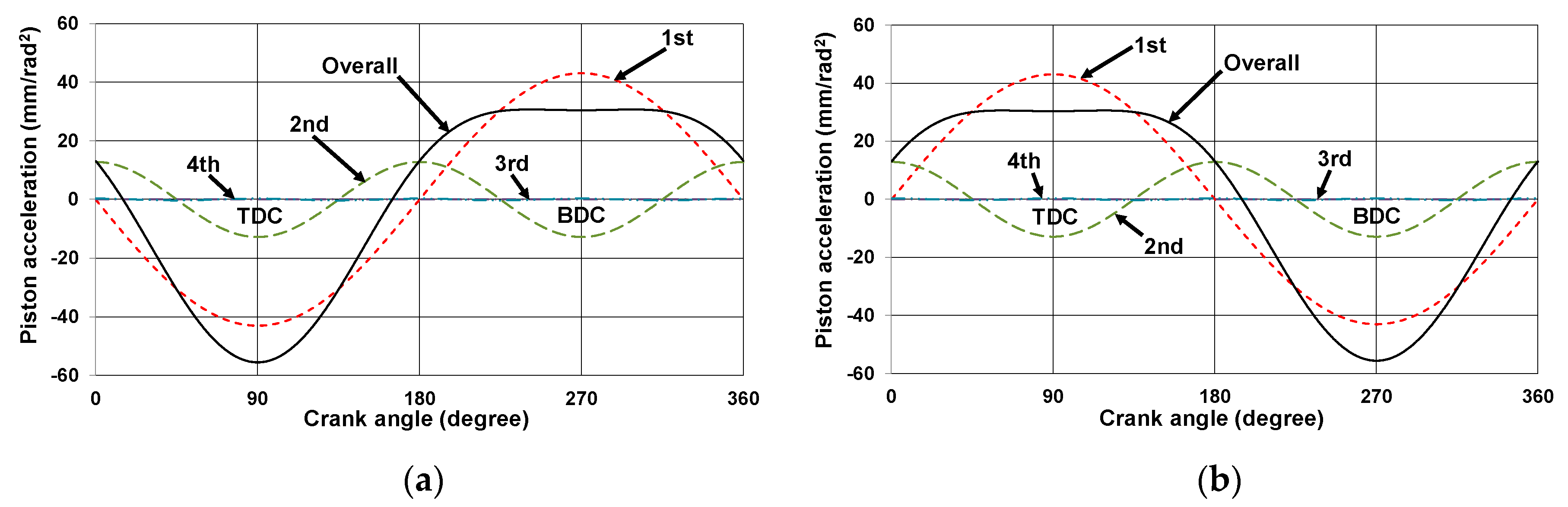
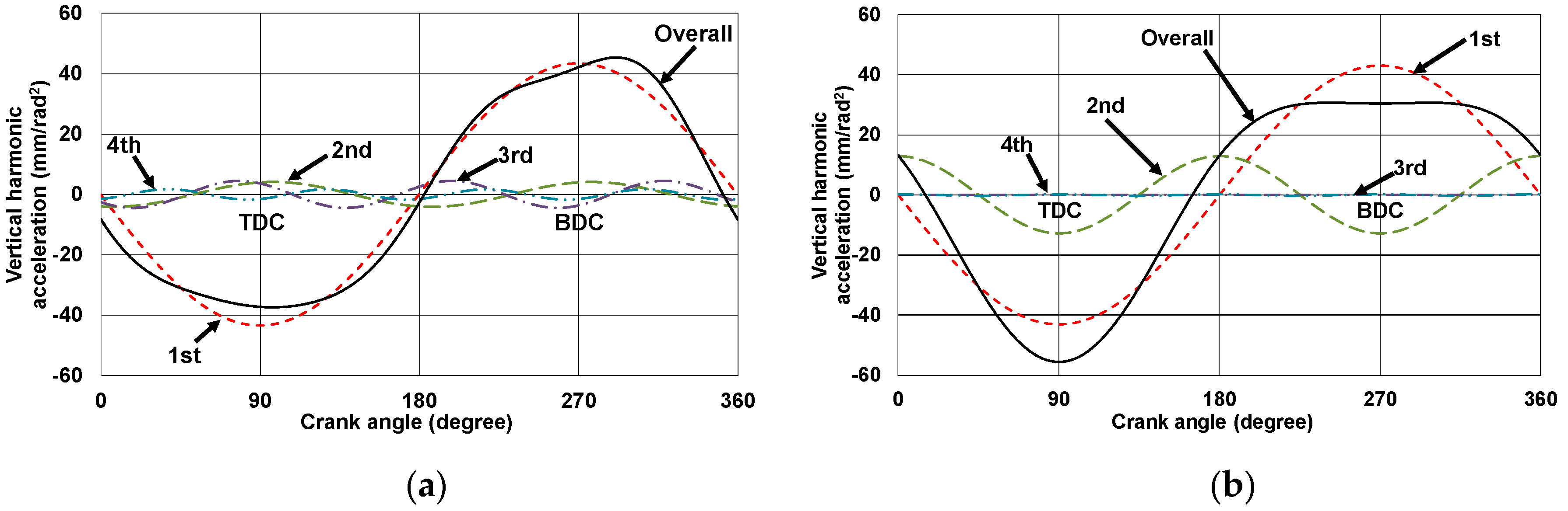
Applsci 10 03765 g001
Figure 2. Harmonic acceleration components at the piston pin of slider-crank mechanism: (a) Cylinder 1 and (b) Cylinder 2.
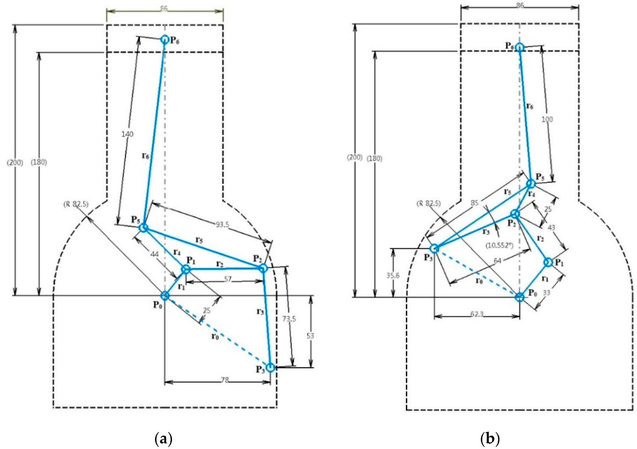
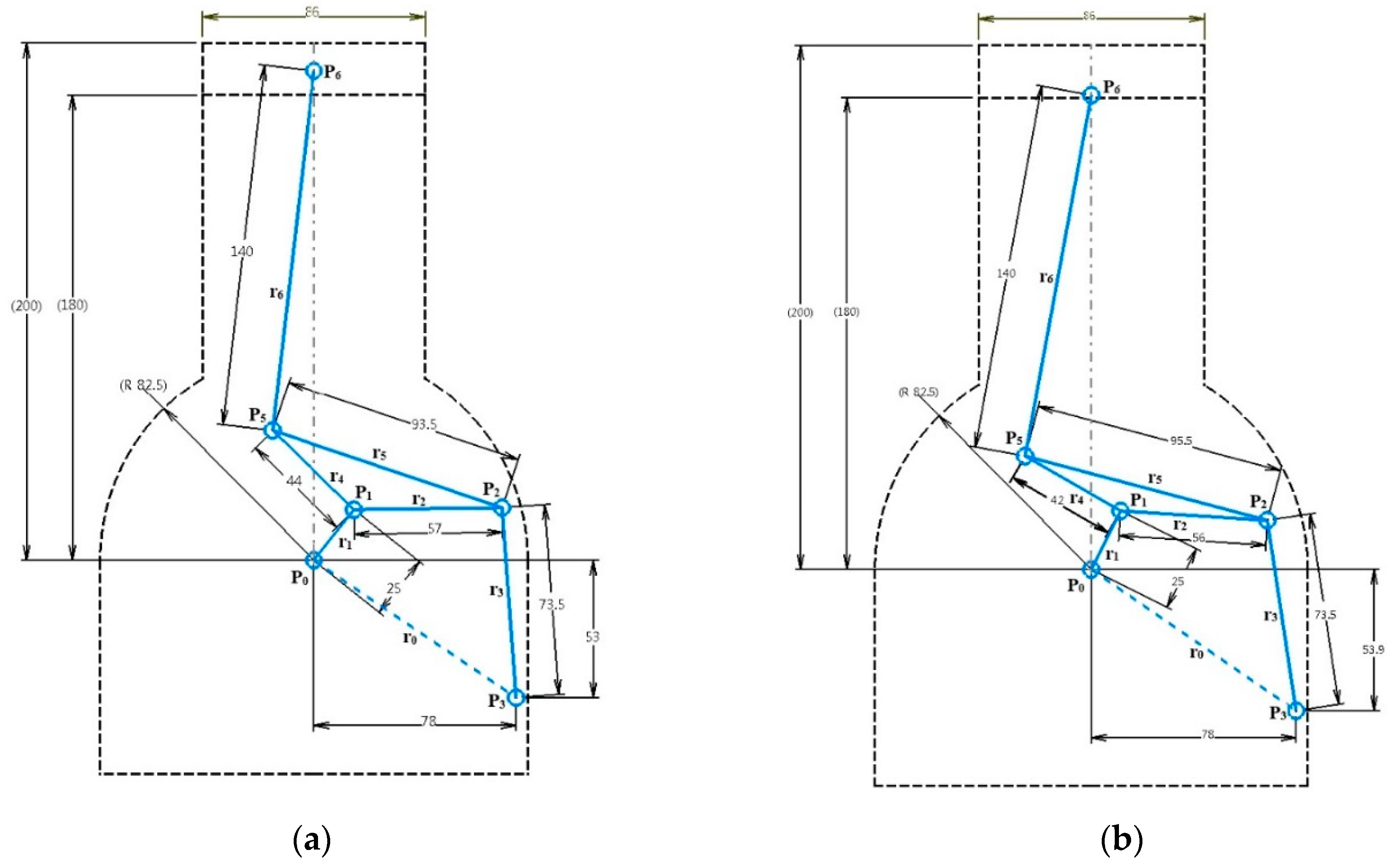
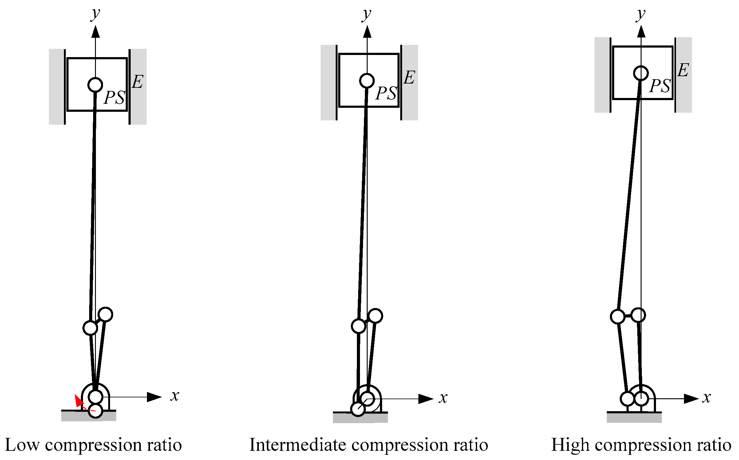
Applsci 10 03765 g002
Figure 3. Initial design of VCR engine mechanisms: (a) Stephenson III and (b) Watt II.
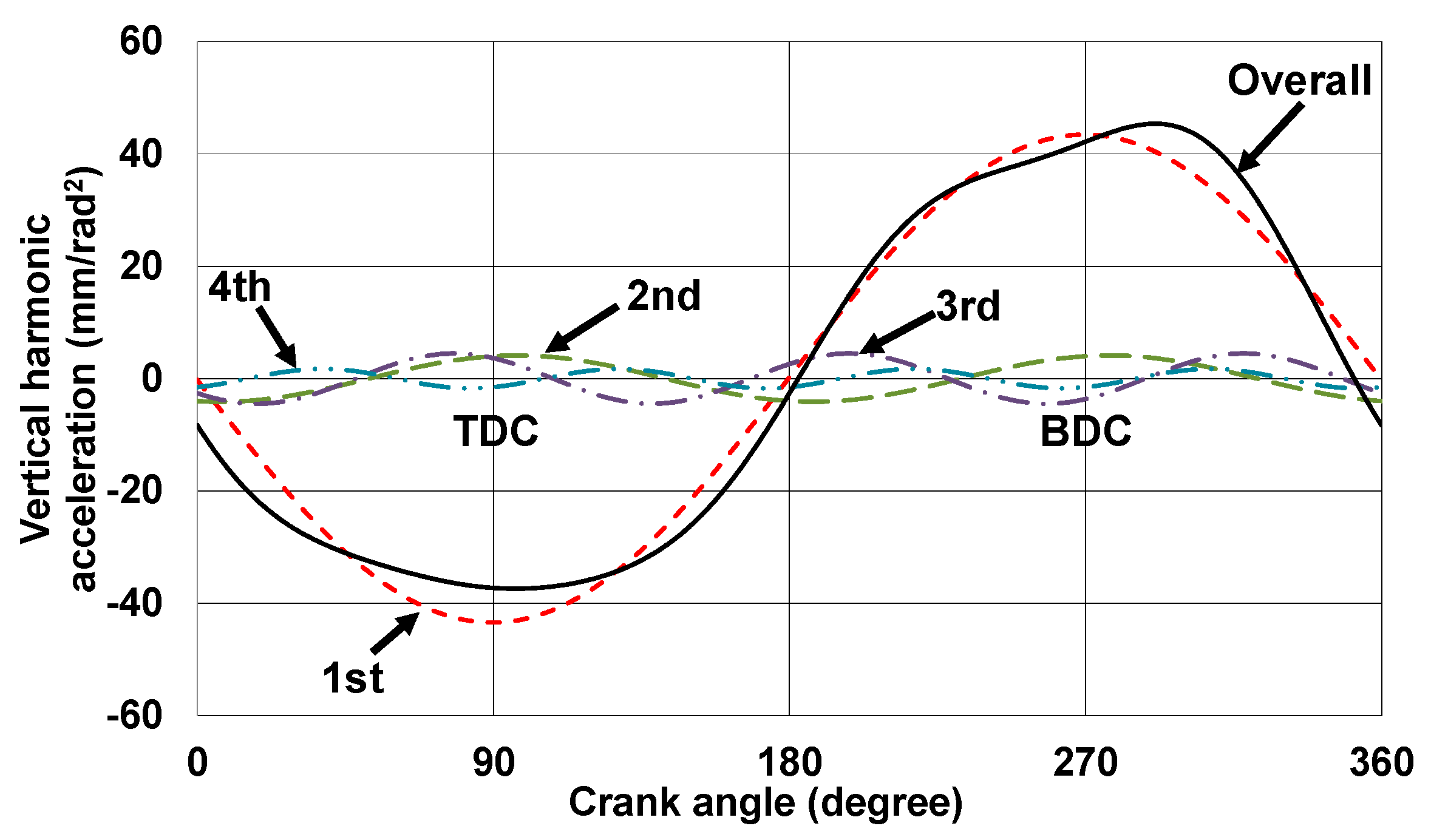
Applsci 10 03765 g003
Figure 4. Vertical harmonic acceleration components at piston pin (P6) of the initially designed Stephenson III mechanism in a single cylinder.
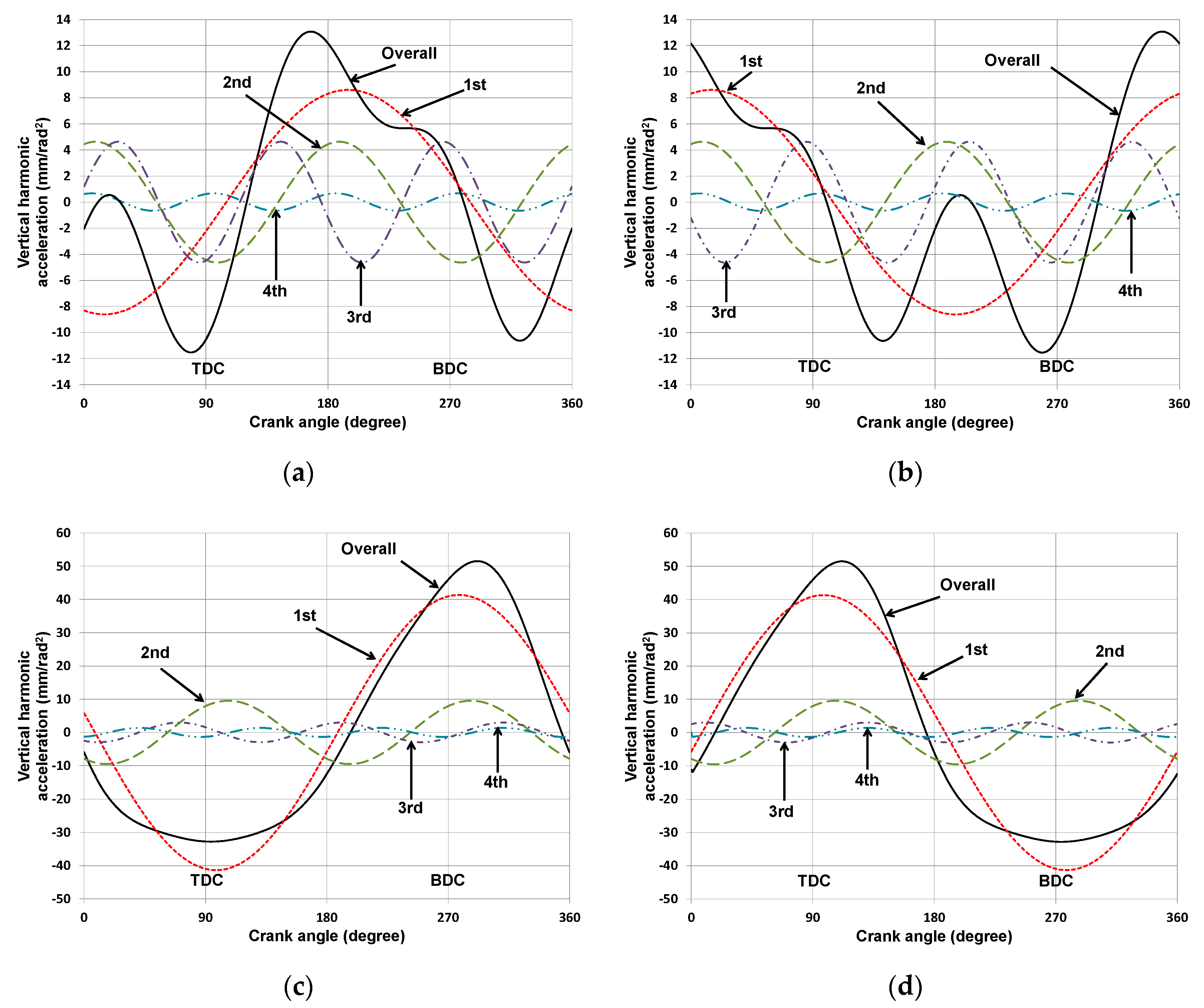
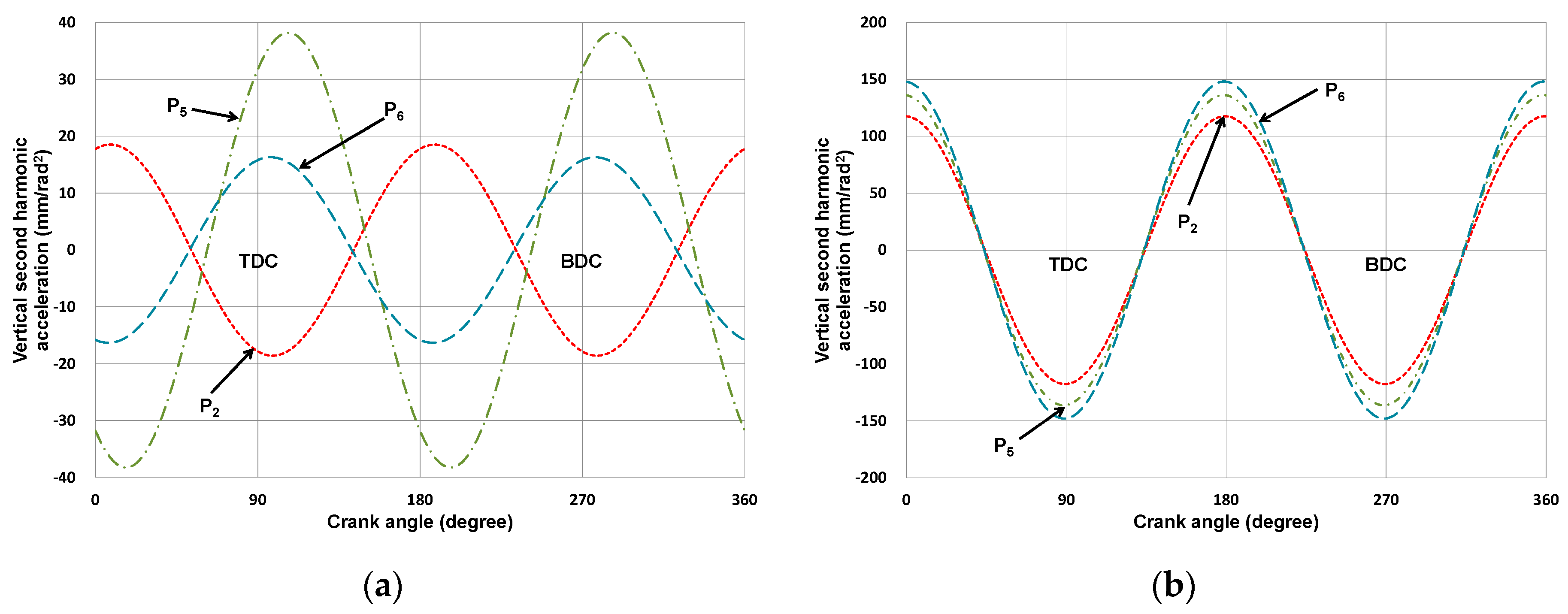
Applsci 10 03765 g004
Figure 5. Vertical harmonic acceleration components at joints P2 and P5 of the initially designed Stephenson III mechanism: (a) Joint P2 in Cylinder 1; (b) Joint P2 in Cylinder 2; (c) Joint P5 in Cylinder 1; and (d) Joint P5 in Cylinder 2.
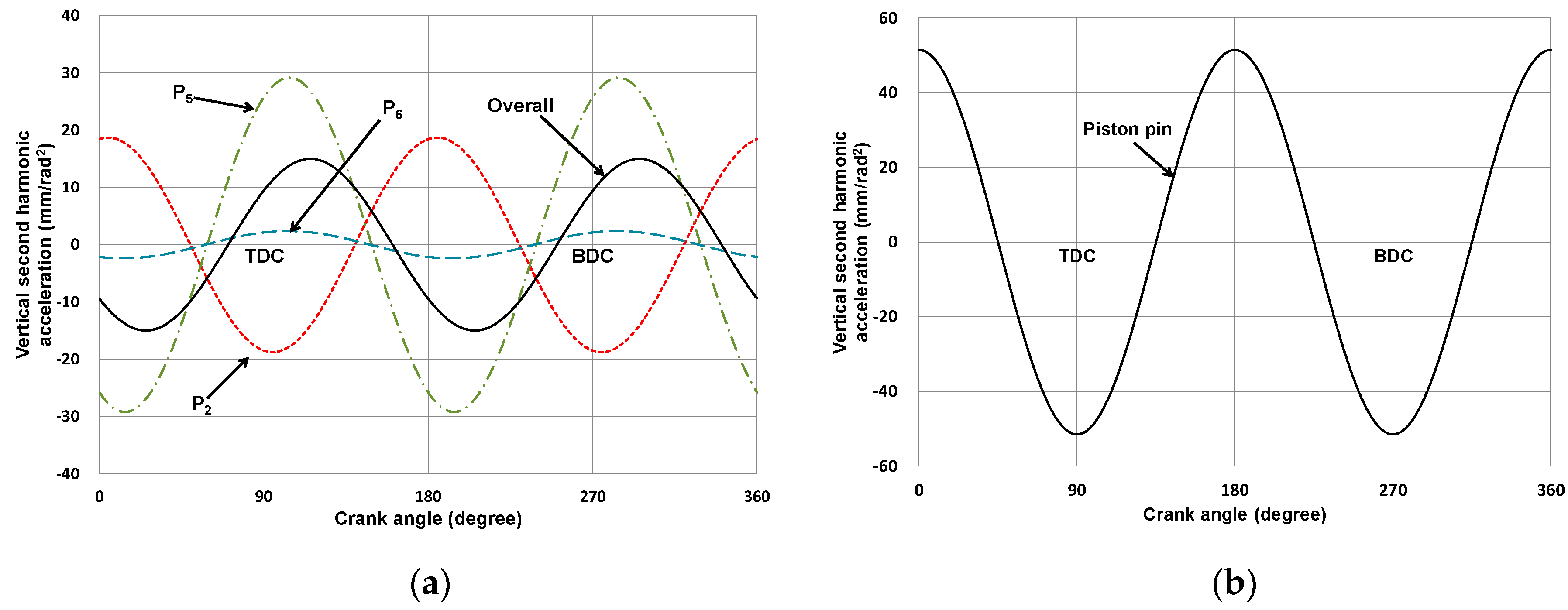
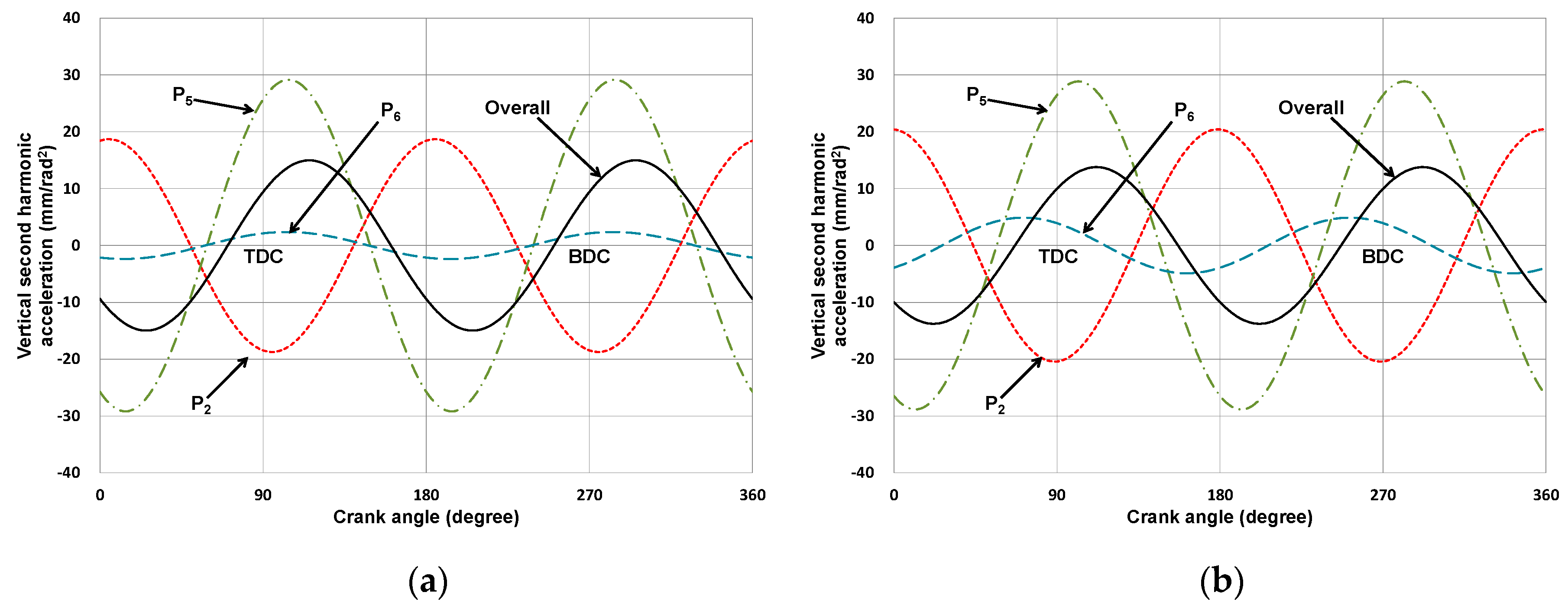
Applsci 10 03765 g005
Figure 6. Vertical second harmonic acceleration at each joint in candidate mechanisms in the in-line four-cylinder engine: (a) initially designed Stephenson III and (b) initially designed Watt II.
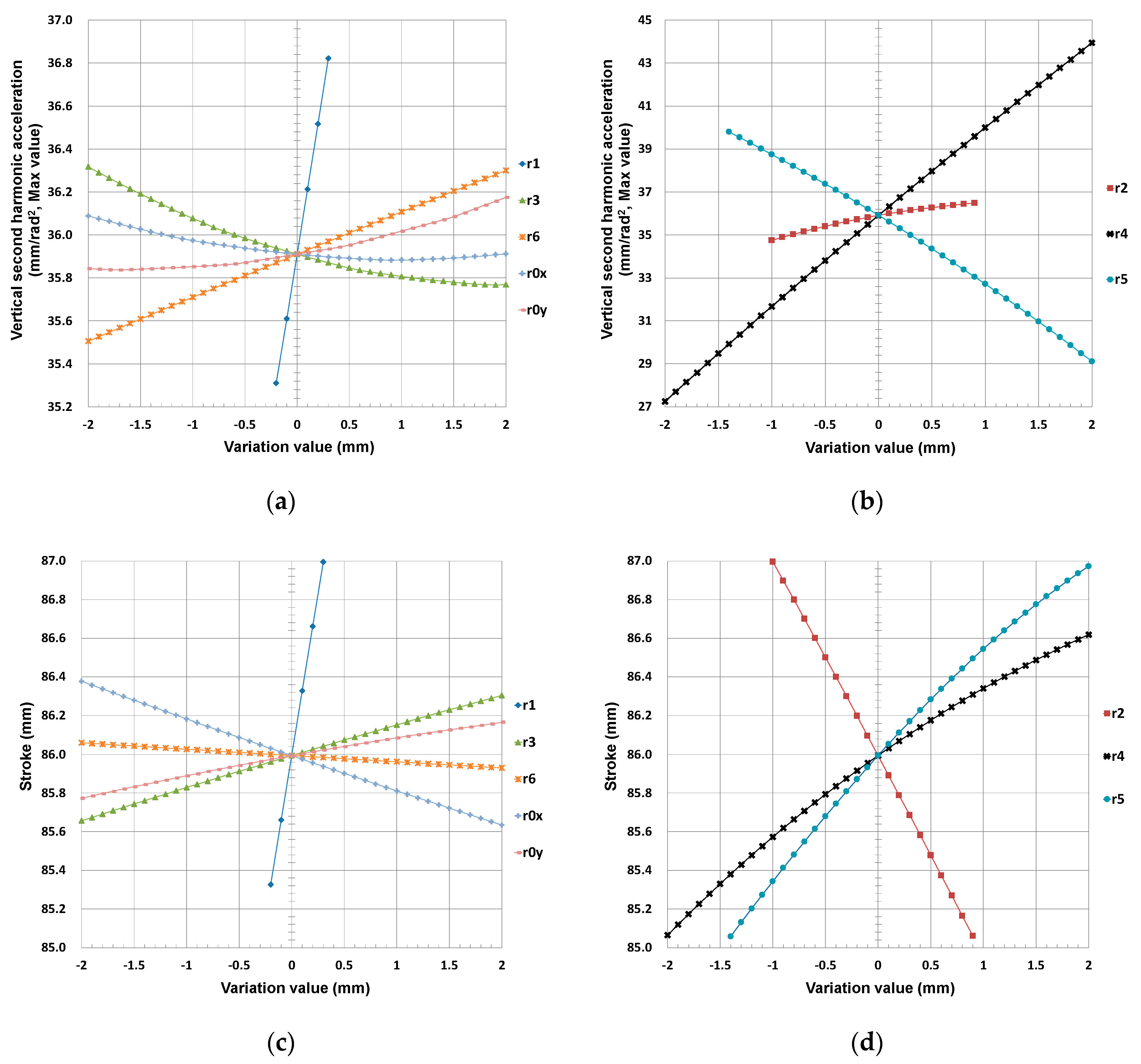
Applsci 10 03765 g006
Figure 7. Influence on the maximum of vertical second harmonic acceleration sum of length change in: (a) r1, r3, r6, r0x, and r0y and (b) r2, r4, and r5 of the ternary link; influence on the stroke of length change in: (c) r1, r3, r6, r0x, and r0y and (d) r2, r4, and r5 in the in-line four-cylinder engine.
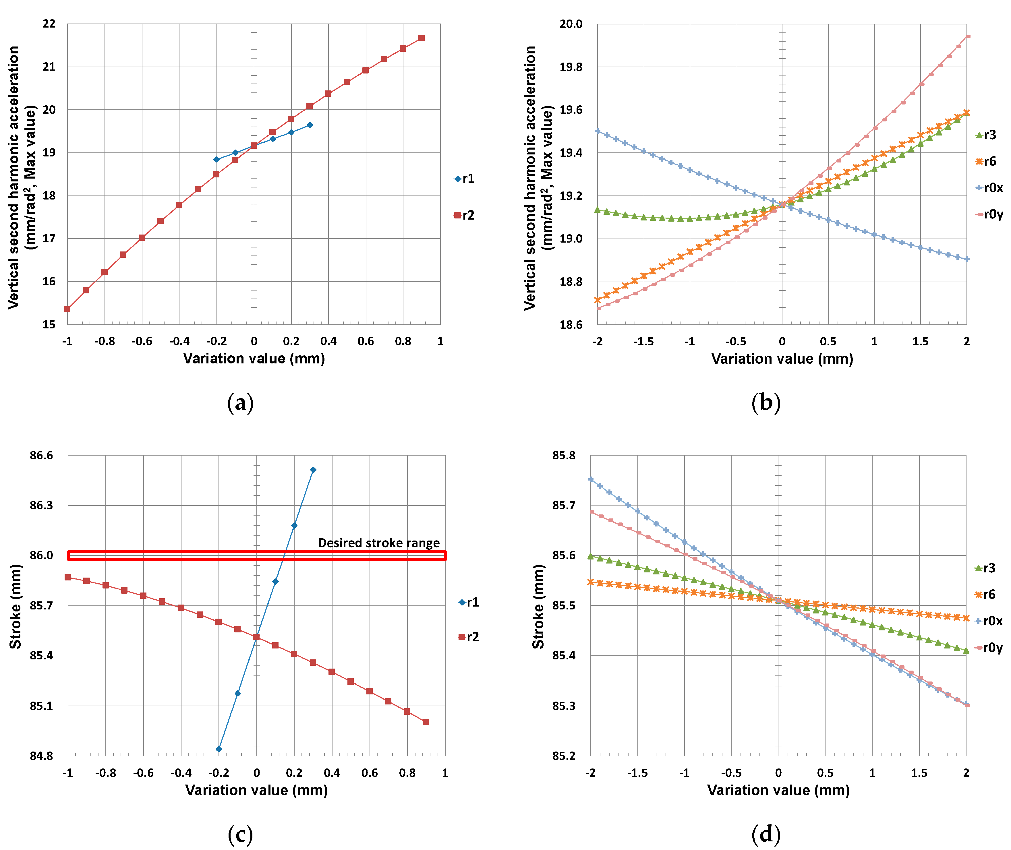
Applsci 10 03765 g007
Figure 8. With the minimum length of r4 and the maximum r5, influence on the maximum of vertical second harmonic acceleration sum of length change in: (a) r1 and r2 and (b) r3, r6, r0x, and r0y; influence on the stroke of length change in: (c) r1 and r2 and (d) r3, r6, r0x, and r0y in the in-line four-cylinder engine.
Applsci 10 03765 g008
Figure 9. Adjusted stroke and maximum value of vertical second harmonic acceleration sum in each case: (a) adjusted stroke and (b) maximum vertical second harmonic acceleration sum in the in-line four-cylinder engine.
Applsci 10 03765 g009
Figure 10. Stephenson III VCR engine mechanism: (a) initial design and (b) final design.
Applsci 10 03765 g010
Figure 11. Vertical harmonic acceleration components at piston pin in single cylinder engine: (a) final design of the Stephenson III mechanism and (b) the slider-crank mechanism.
Applsci 10 03765 g011
Figure 12. Vertical second harmonic acceleration components at each joint in four-cylinder engine: (a) final design of the Stephenson III mechanism and (b) the slider-crank mechanism.
Applsci 10 03765 g012
Figure 13. Vertical second harmonic acceleration components at joints of the Stephenson III mechanism in the four-cylinder engine: (a) proposed method and (b) optimization using commercial software.
Applsci 10 03765 g013
Figure 14. Stephenson III VCR engine mechanisms with double-crank type four-bar linkage.
Applsci 10 03765 g014
Table 1. Candidate variable compression ratio (VCR) engine mechanisms.
Stephenson ChainWatt Chain
Unlabeled Graph Applsci 10 03765 i001 Applsci 10 03765 i002
Stephenson III MechanismWatt II Mechanism
Labeled Graph Applsci 10 03765 i003 Applsci 10 03765 i004
Skeleton diagram Applsci 10 03765 i005 Applsci 10 03765 i006
◉: ground link, E: engine block, PS: piston, r1: crank, r6: connecting rod, TL: ternary link, R: revolute joint, P: prismatic joint, Pi: position of joint i.
Table 2. Design specifications for VCR engine mechanism.
Engine TypeIn-Line Four-Cylinder
Crank throw phase angle90°, 270°, 270°, 90°
Bore86 mm
Stroke86 ± 0.025 mm
TDC position220 ± 10 mm (Piston pin: 190 ± 10 mm)
Displacement2 L
Piston offset0 mm
Radius of engine block internal space82.5 mm (measured form crank center)
Table 3. Dimensions of the initially designed VCR engine mechanisms.
LinkLink Length and Pivot Position (Unit: mm)
Stephenson III MechanismWatt II Mechanism
r125.00033.000
r257.00043.000
r373.50064.000
r444.00025.000
r593.50085.000
r6140.000100.000
r0x78.000−62.300
r0y−53.00035.600
Table 4. Analysis results of the initially designed mechanisms.
Stephenson IIIWatt IIDesign Specifications
Stroke (mm)85.99386.00886 ± 0.025
Piston pin position at TDC (mm)197.391199.191190 ± 10
Table 5. Prescribed tolerances.
Link Lengthsri ± 2 mm
Stroke86 ± 1 mm
Table 6. Link length variation cases for Step S3.
CaseVariation NumberLink Length
r2r3r4r5r6r0y
1Decrease r3 with min. r2, r4, and max. r515673.54295.5140−53
:56:4295.5140−53
215671.54295.5140−53
2Decrease r6 with min. r2, r4, and max. r515673.54295.5138−53
:5673.54295.5:−53
215673.54295.5140−53
3Decrease r0y with min. r2, r4, and max. r515673.54295.5140−53
:5673.54295.5140:
215673.54295.5140−55
The “:” in the table means the variation range as “-“. For example, the “1 : 21” and “73.5 : 71.5” for r3 in Case 1 mean that the variation Number “1, 2, 3, …, 21” correspond “73.5, 73.4, 73.3, …, 71.5” of r3.
Table 7. Comparison of the initial and final mechanism.
UnitInitial DesignFinal DesignEffect (%)
Linkr1mm25.00025.000
r2mm57.00056.000
r3mm73.50073.500
r4mm44.00042.000
r5mm93.50095.500
r6mm140.000140.000
r0xmm78.00078.000
r0ymm−53.000−53.900
ResultStrokemm85.99486.018
Piston pin position at TDCmm197.391185.124
Max. of 2nd harmonic acceleration summm/rad235.91114.963−58.333
Max. of 4th harmonic acceleration summm/rad210.7146.977−34.882
Table 8. Comparison of the results of the proposed method and the constrained optimization.
UnitInitial DesignResult of Proposed MethodResult of OptimizationEffect (%)
Linkr1mm25.00025.00024.95798-
r2mm57.00056.00056.00000-
r3mm73.50073.50073.44895-
r4mm44.00042.00042.00000-
r5mm93.50095.50095.49999-
r6mm140.000140.000138.0000-
r0xmm78.00078.00080.00000-
r0ymm−53.000−53.900−55.00000-
ResultStrokemm85.99486.01885.975-
Piston pin positionmm197.391185.124184.424-
Max. 2nd harmonic acceleration summm/rad235.91114.96313.773−7.940
Max. 4th harmonic acceleration summm/rad210.7146.9777.114+1.997
Table 9. Vertical second harmonic acceleration components in the finally designed single-cylinder Stephenson III with crank-rocker four bar at low and high compression ratios.
MechanismUnitStephenson III (Crank-Rocker)Slider Crank
Compression ratio-816.5-
r0xmm72.10078.000-
r0ymm−46.900−53.900-
Strokemm85.50286.01886.000
2nd harmonic acceleration at piston pinm/s23.7010.58812.691
Max. 2nd harmonic acceleration summ/s25.5423.69212.691

