A Novel Energy Optimization Control Strategy for Electric Drive System Based on Current Angle


1
State Key Laboratory of Mechanical Transmissions, Chongqing University, Chongqing 400044, China
2
School of Automotive Engineering, Chongqing University, Chongqing 400044, China
*
Author to whom correspondence should be addressed.
Appl. Sci. 2020, 10(11), 3778; https://doi.org/10.3390/app10113778
Submission received: 13 April 2020
/
Revised: 19 May 2020
/
Accepted: 25 May 2020
/
Published: 29 May 2020
(This article belongs to the Special Issue Electric (Hybrid) Vehicles: Optimization Techniques, Control Systems and Powertrain Modeling - selected papers from conference EVER2021)
Abstract
:The combination of permanent magnet synchronous motor (PMSM) and inverter is the key electric drive system (EDS) of electric vehicles (EVs), and its overall efficiency seriously affects the energy consumption of EVs. In order to further improve the efficiency of PMSM-inverter, the influence of a special control object current angle β on EDS was studied and the general rule between β and EDS efficiency was obtained in this paper. Then, the golden section search (GSS) method was used to obtain optimal β and its corresponding stator current is, which can realize EDS working in optimal efficiency in the whole EDS working area. On this basis, an overall efficiency optimization control strategy for EDS based on the current angle β look-up table was proposed in this paper. To verify the effectiveness of the proposed control strategy, simulation considering iron loss and copper loss of motor and inverter loss was completed, which showed that compared with traditional control, the control strategy proposed in this paper can effectively improve the working efficiency of EDS under steady state and transient state.
1. Introduction
1.1. Motivation
With the aggravation of greenhouse effect and the consumption of fossil energy, automobile companies are developing pure electric vehicles (EVs) vigorously to reduce emissions and improve fuel economy [1]. The efficiency of electric drive system (EDS) is a key factor affecting the energy consumption of the whole vehicle and EVs with high EDS efficiency can bring good driving experience to the driver [2], so it is essential to further improve the EDS efficiency.
1.2. Literature Review
Recently, the efficiency of motor has been improved by motor structure optimizing, vehicle control strategy, and motor loss minimization algorithm (LMA). In the motor manufacturing stage, the energy consumption characteristics of the motor can be improved by optimizing the structure of the motor, including the shape, material, geometric dimension, and so on [3,4,5,6]. When the motor is manufactured and installed on the vehicle, the working point of the motor can be changed as much as possible through different vehicle structures and vehicle control strategies to improve the power and economy of the vehicle, such as dual motor drive system and corresponding coordinated control strategy [7,8], two-speed automated manual transmission (AMT)-motor system with shift control strategy [9]. In addition, the most widely used method to improve the efficiency of the motor is LMA [10,11,12,13,14,15,16,17,18,19,20,21,22,23,24], which search the optimal control variables (usually dq-axis current id/iq) of the motor through the loss model, so that the efficiency of the motor is the highest under the given speed and torque.
At present, LMAs to improve the motor efficiency can be divided into two categories: Online search control (OSC) and loss model control (LMC). OSC is less affected by the motor parameters. According to the state feedback of the machine, different methods were proposed to give the increment of the optimal direction of motor current vector during each iteration, such as neural network [10], golden section search (GSS) [11], collaborative optimization control strategy based on sliding mode controller [12], and online optimization [13]. The electric time constant of the motor is very small, which can reach microsecond level, so the OSC will occupy a lot of computing resources and its response speed is slow. Compared with it, LMC has the advantages of fast response speed, good dynamic characteristics, and so on. It is often used in motor in practical application. LMC uses the motor loss model to calculate the optimal control parameters of the motor, so that the motor efficiency is the highest. Some scholars used methods like formula calculation [14], linear optimization [15], and nonlinear programming [16] to optimize the of motor armature current vector, which improved the efficiency of motor. However, in reality, the characteristics of motor are complex and changeable, and such LMC means are no longer suitable for the current needs. Now, scholars put more interest in table lookup control (LUTC). This kind of LMC obtains the optimal control value of each working point through the motor loss model to make an offline look-up table, and then control the motor by looking up the offline look-up table according to the current state of the motor. In light of different optimization objects, LUTC is divided into DC bus voltage Udc optimization control [17,18], inverter switching frequency fpwm optimization control [19], and furthermore, the optimization control of DC bus voltage combined with inverter switching frequency was proposed [20]. It should be mentioned that in order to better control the motor, the optimization objects of most LUTC are flux linkage φf [21,22] and dq-axis current id/iq [23], which is more effective for the control of copper loss and iron loss in motor. Furthermore, inverter switching frequency fpwm was added to the optimization [24], but id/iq and fpwm were considered separately.
In brief, most of the above LMA studies focus on the control strategy of id/iq, which can effectively reduce the loss of motor itself. However, it is still of great potential and reference value to explore effective motor control strategies. Moreover, the above LMA studies often focus on the loss of the motor, and few studies consider the loss of the inverter at the same time. Other works solely consider the efficiency of the inverter. One method is adopting advanced power devices [25,26]. The other one is proposing some new pulse width modulations (PWM) [27,28]. In fact, the EDS consists of inverter and motor. It is more reasonable to evaluate the overall efficiency of EDS, namely the efficiency of motor and inverter, rather than only considering the efficiency of motor or inverter.
1.3. Original Contributions of this Paper
Aiming at further reduce the overall loss of EDS and explore the feasibility of new motor control object, EDS loss model considering copper loss, iron loss, and inverter loss was established in this paper. Then, this paper studied the influence on EDS based on a new control object current: Angle β (the angle between stator current is and d-axis) and proposed a novel energy optimization control strategy based on β look-up table for EDS. The original contributions of this paper are as follows:
- The influence of current angle β on EDS efficiency was studied and the general rule between β and EDS efficiency was obtained in this paper, which provides a reference for future research.
- The optimization range and the calculation amount of β to get the best EDS efficiency in the whole operating range was reduced by GSS search algorithm.
- An energy optimization control strategy based on β look-up table was proposed in this paper. Compared with the traditional control strategy, the proposed control strategy can make EDS run over the whole vehicle operational range at an efficient point without affecting the performance and improve the efficiency of EDS.
2. Electric Drive System Loss Model
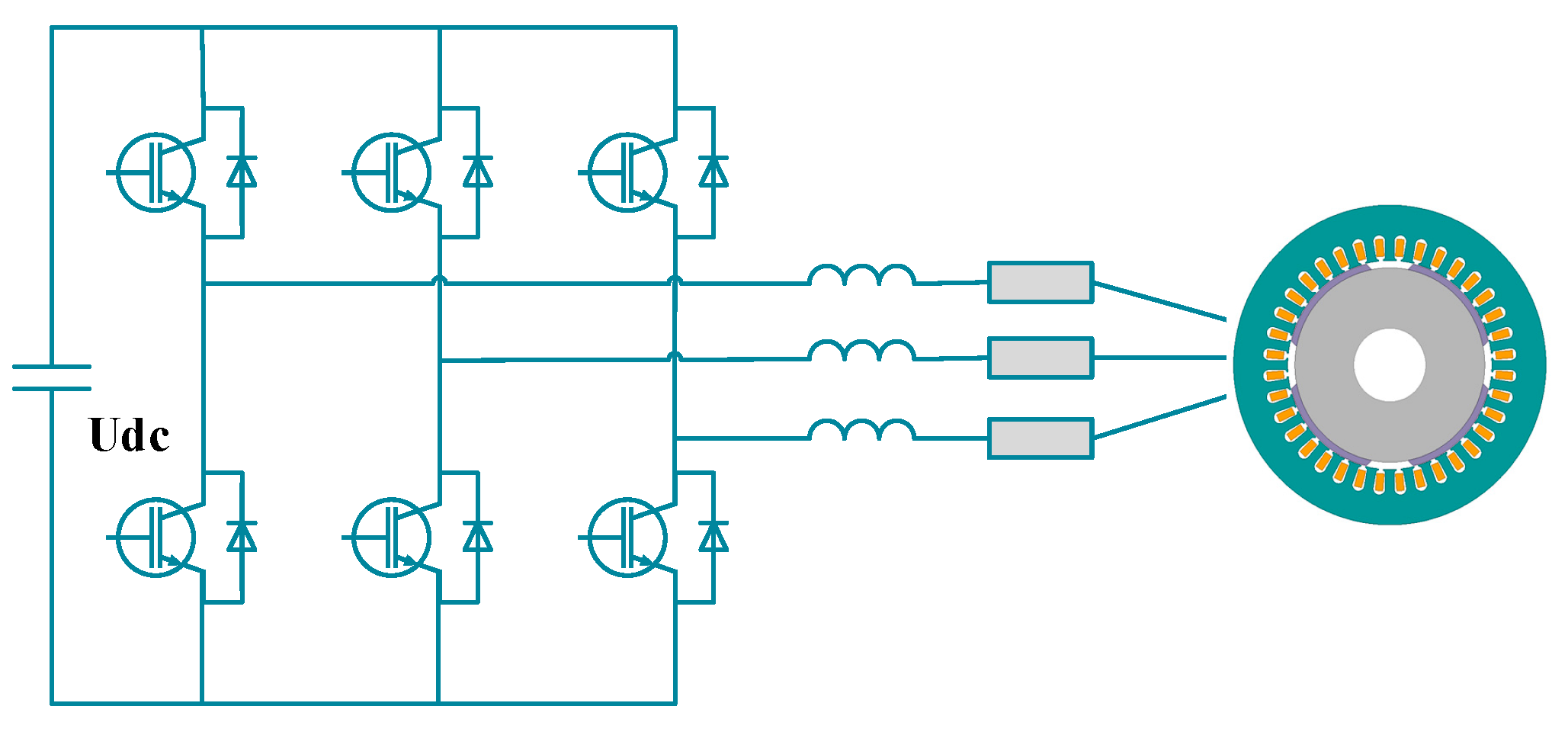
The general electric drive system (EDS) is shown in Figure 1, which is composed of permanent magnet synchronous motor (PMSM) and inverter (six insulated gate bipolar transistor (IGBT) modules). In order to optimize the energy consumption characteristics of EDS, the loss model of EDS needs to be established. The loss of EDS is divided into motor loss and inverter loss. Among the motor losses, copper and iron losses are controllable, whereas stray loss and mechanical loss were very small and almost unchanged, which have little effect on EDS efficiency, so they can be ignored. Inverter loss (loss of six IGBT modules) is divided into conduction loss and switching loss.
2.1. Mathematical Motor Loss Model
Generally, there are two modeling methods of motor: Finite element modeling and mathematical modeling. The finite element model of the motor can accurately reflect the internal loss in motor and other nonlinear phenomena, such as demagnetization and inductance change [29]. However, this kind of method takes up a lot of computing resources and is often used in the performance simulation of motor rather than the research of control strategy, so this paper used MATLAB/ Simulink (Version 2018 b) to complete the mathematical modeling. In this paper, a surface mounted permanent magnet synchronous motor is used for research. Its parameters are as Table 1.
The controllable loss of motor includes copper loss and iron loss. The loss caused by resistance heating of the motor winding is called copper loss. Meanwhile, iron loss is caused by hysteresis effect and stator eddy current, among which the former is caused by the blocking effect of the iron core on the flux flow of the stator, and the latter is caused by the eddy current generated by the induced electromotive force on the cross section of the iron core. To consider the influence of iron loss, an iron loss resistance Rc is paralleled in the dynamic equivalent circuit diagram of permanent magnet synchronous motor, as shown in Figure 2. The equivalent equation of voltage in this model is [30]:
where id, iq are the armature current vector of d-axis and q-axis, respectively. Ud, Uq are the voltage vectors of d-axis and q-axis, respectively. icd, icq are the iron loss current of d-axis and q-axis, respectively. iod, ioq are the effective current vectors of d-axis and q-axis, respectively. Ld, Lq are the inductance of d-axis and q-axis, respectively. Rs is copper loss resistance; Rc is the core loss resistance; φf is the flux linkage. ωe is the electric angular velocity. ρ is the salient rate.
Copper loss is caused by the resistance heating when the stator armature passes through the stator winding, and its valve is related to the armature current and copper loss resistance. In the equivalent circuit of this paper, the expression is:
Substituting Equations (3), (4) and (6), copper loss can be derived to be:
The expression of iron loss is as follows:
Substituting Equations (4) and (8), it can be derived to be:
So, the loss of the motor can be written as:
2.2. Inverter Loss Model
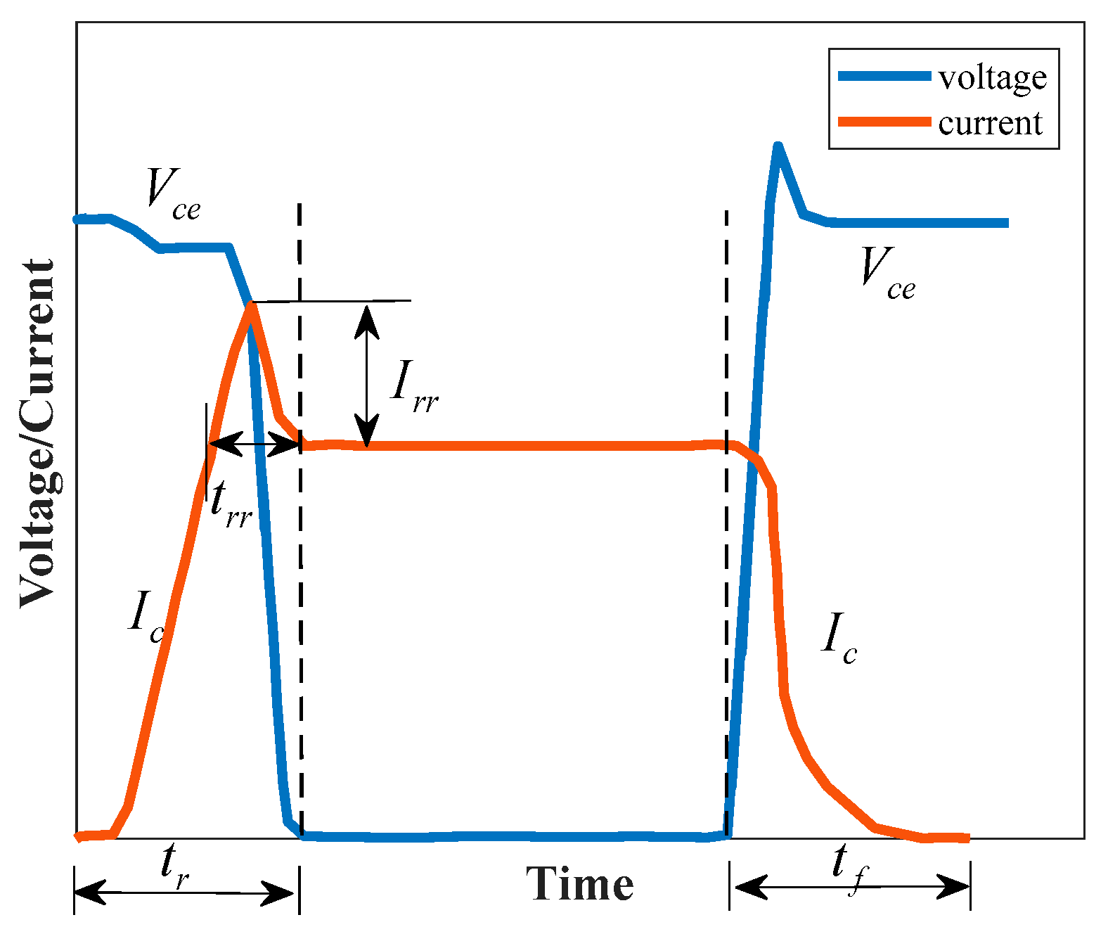
The loss of inverter mainly occurs when the voltage and current of IGBT module (IGBT + free-wheeling diode (FWD)) produces overlapping area in the switching process, which is usually defined as conduction loss and switching loss. Figure 3 shows the working process of voltage and current through the IGBT module in a switching cycle.
Ic is the current between diode collector and emitter. Vce is collector-emitter voltage. tr is the time required for the current to reach the target value in the opening process of IGBT. tf is the time required for the current to reach the target value in the switching-on process of IGBT. trr is the time required for FWD reverse recovery process. Irr is the reverse current through FWD in reverse recovery process.
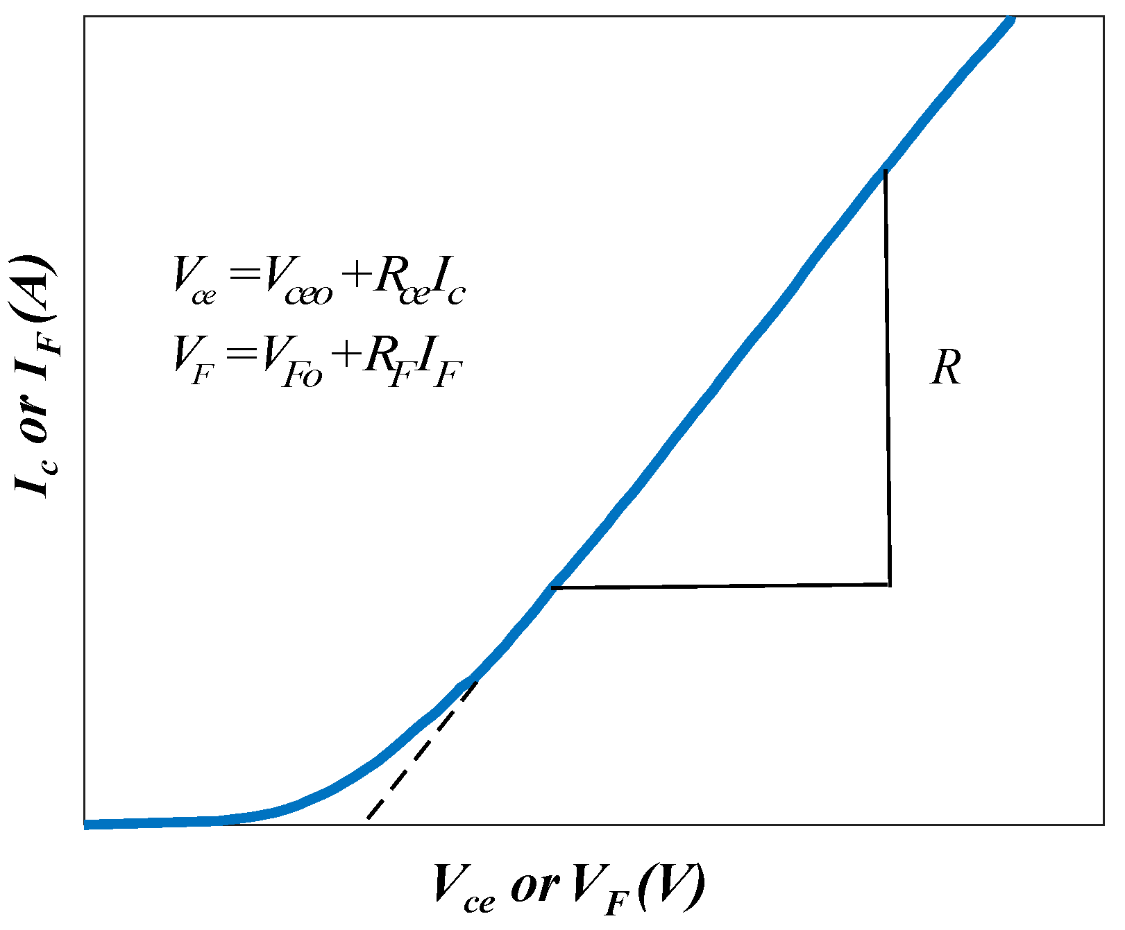
The relationship of collector current and collector-emitter voltage between IGBT and FWD is shown in Figure 4. The collector-emitter voltage Vce and the FWD conduction voltage VF can be fitted with a threshold voltage and a voltage drop with a slope of resistance respectively [32]:
where Vcen is the value of Vce under rated current. Vceo is the threshold voltage. Icn is the rated value of Ic. VFn is the voltage drop of FWD under rated current. VFo is the threshold voltage of FWD.
SVPWM is adopted as the modulation method in this paper, and its AC current is:
where ψ is the power factor angle and Icm is the peak phase current.
The switching loss includes the turn on loss Eon, turn off loss Eoff, and reverse recovery loss Err. Eon, Eoff, Eoff are, respectively, as:
where Irrn is the value of Irr under rated current Ic.
Consequently, the total loss power of the inverter containing six IGBT modules is:
It should be noted that this paper adopted the inverter of model 6MBI100XBA120-50 produced by Fuji Electric, and the data are from the website [34].
2.3. Electric Drive System Efficiency Model
The input power of the EDS is the sum of the output power of motor and total loss of EDS, so the efficiency of the EDS is calculated by the following formula:
where Pout is the motor output power. Te is the motor output electromagnetic torque. ωm is the motor angular speed.
3. Efficiency Optimization Control Based on Current Angle Look-Up Table
β is the angle between stator current is and d-axis, as shown in Figure 5, and there are few researches on the optimization of EDS efficiency based on it at present. As described in Section 1, conventional motor efficiency optimization control (such as MTPA control) improves motor efficiency by optimizing dq-axis current id/iq, but it should be noted that two factors need to be considered: The current limit and voltage limit. Therefore, the conventional id/iq optimization usually adds a current amplitude calculation module to reach the limit of current limit value, which will lead to the increase of calculation amount. The constraints of motor stator current and voltage are as follows.
where ilim and Udc_lim are the current limit and DC bus voltage limit, respectively.
However, optimization on β will break through this limitation, which means that this research has potential.
3.1. Principle of EDS Efficiency Optimization by Current Angle
The salient rate ρ of PMSM in this paper is 1, so its current limit circle and voltage limit circle can be drawn as Figure 5. MTPA and flux weakening (FW) control are most widely used in motor control. Take MTPA and FW control as examples to analyze the change of motor working state. Generally, MTPA (id = 0) control is applied to the working area before the base speed of the motor, in which the stator current is controlled to move on the q-axis like is1 and β is β1. At this time, the d-axis current of the motor is 0 A, so the copper loss of the motor can be minimized while the iron loss of the motor is not considered. After exceeding the base speed, the stator current will not meet the limit of the voltage limit circle if it was still controlled by MTPA, so it is necessary to increase the component of d-axis current to deflect is to the left like is2 and β is β2., making motor controlled by FW control.
It can be found that with the change of EDS working state, β of the motor is constantly changing as well. From the relationship between the stator current is and the dq-axis current, it can be seen that the change of β will bring the change of id/iq at the same time. By adjusting β, the direction and amplitude of is can be changed, so as to change id/iq and optimize the efficiency of electric drive system.
From the mathematical relationship, id/iq can be written as:
In brief, the direction and amplitude of is can be changed by adjusting the angle between stator current and d axis called β so as to change the dq-axis current and optimize the efficiency of electric drive system. At this time, the is is directly determined by β, and it is unnecessary to judge whether it exceeds the current limit ilim, which will reduce the logic judgment and save more computing resources.
3.2. Study on the Effect of Current Angle on EDS Efficiency
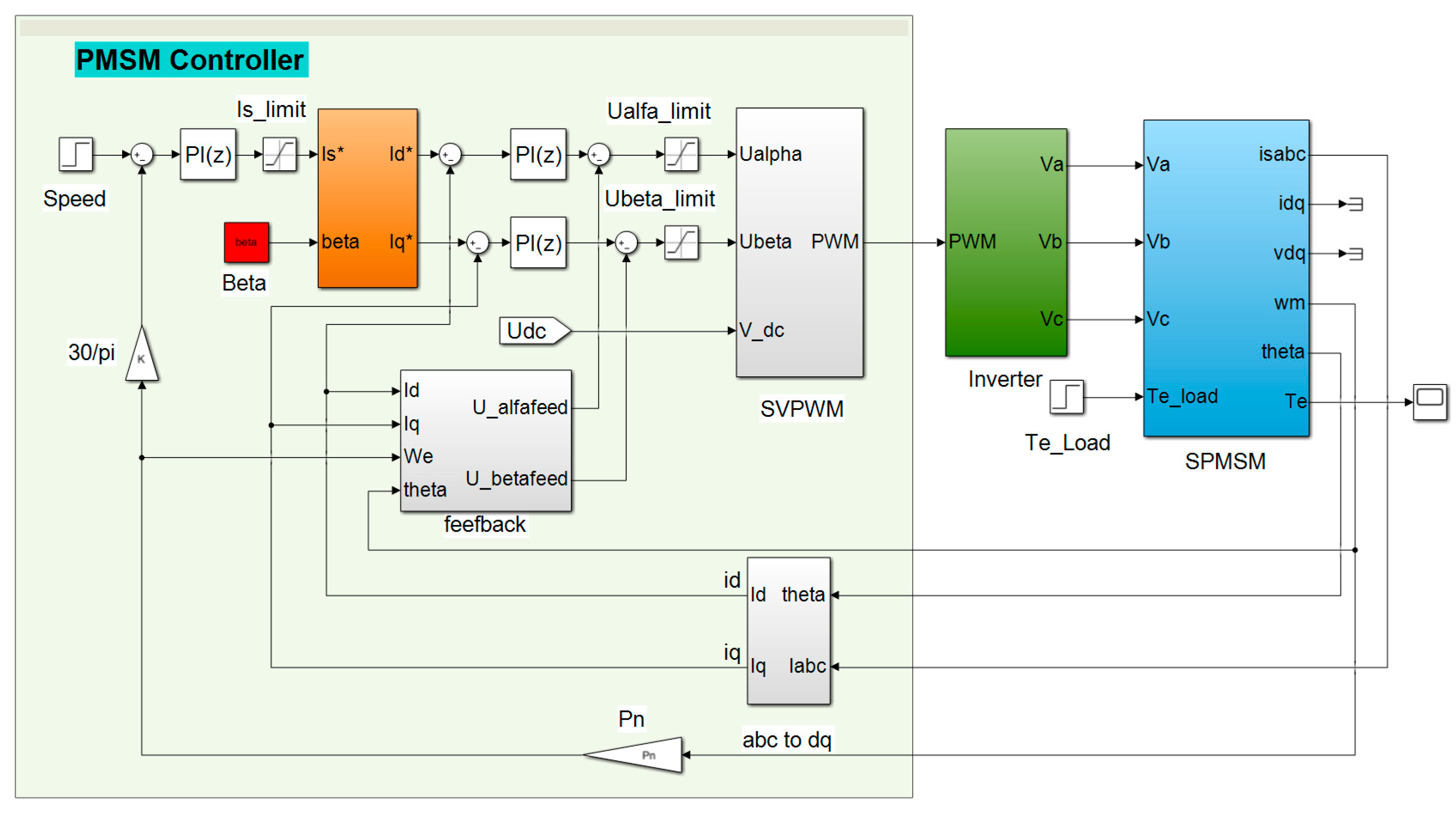
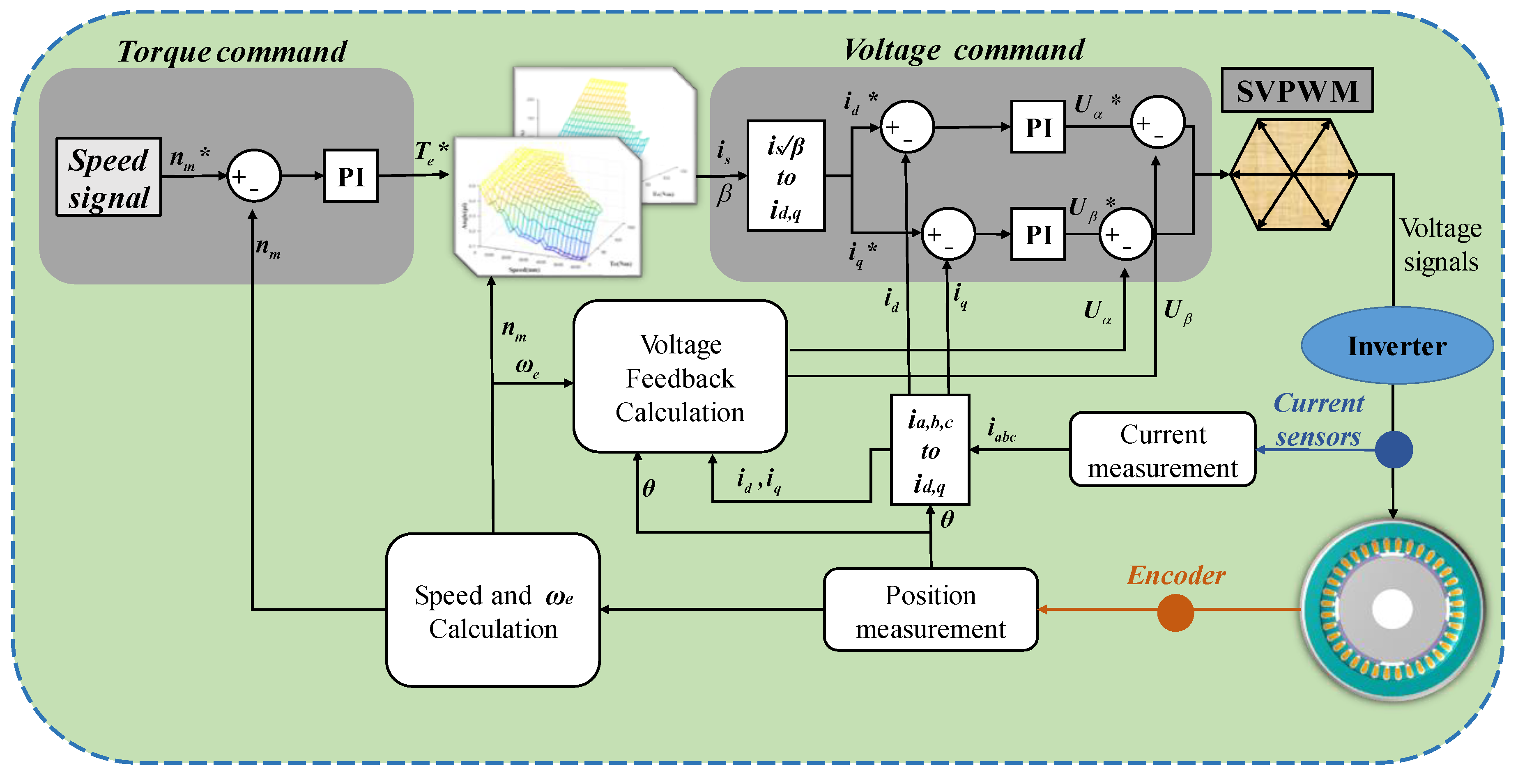
According to Section 2, the inverter and PMSM modules have been modeled. On this basis, this paper established an optimization model with β as the control parameter based on the traditional field-oriented control (FOC) block diagram [35,36] in MATLAB/Simulink, as illustrated in Figure 6. When the motor load torque and speed are given, by changing β (the red input in Figure 6), the motor speed loop PI controller will automatically adjust the stator current is, and generate id and iq through the two current loop PI controllers, so as to make the motor reach the given working condition. It should be noted that when using this optimization method for efficiency optimization, is can be limited within the current limit circle directly by the limiting module after speed loop PI controller, and the voltage can also be limited within the voltage limit circle by the limiting module after the current loop PI controller [37]. Therefore, no additional calculation formula is needed during optimization.
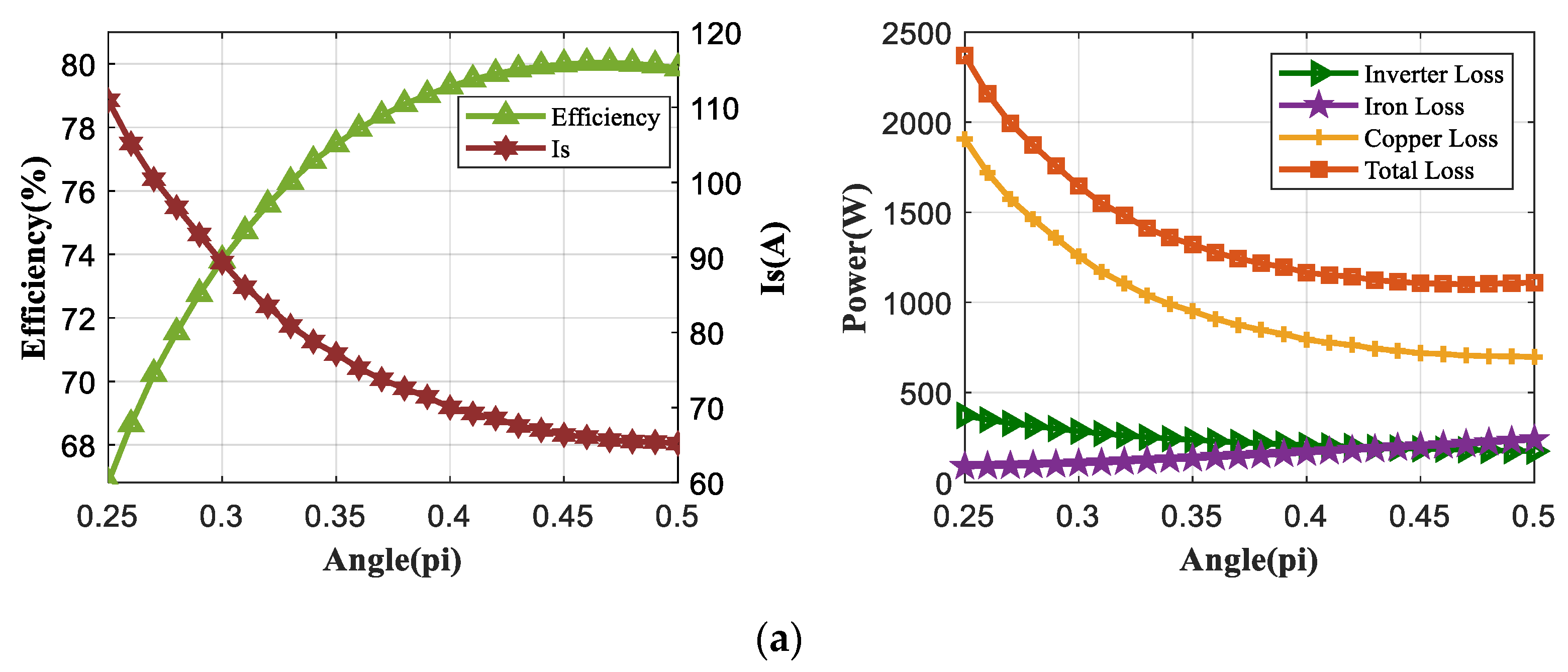
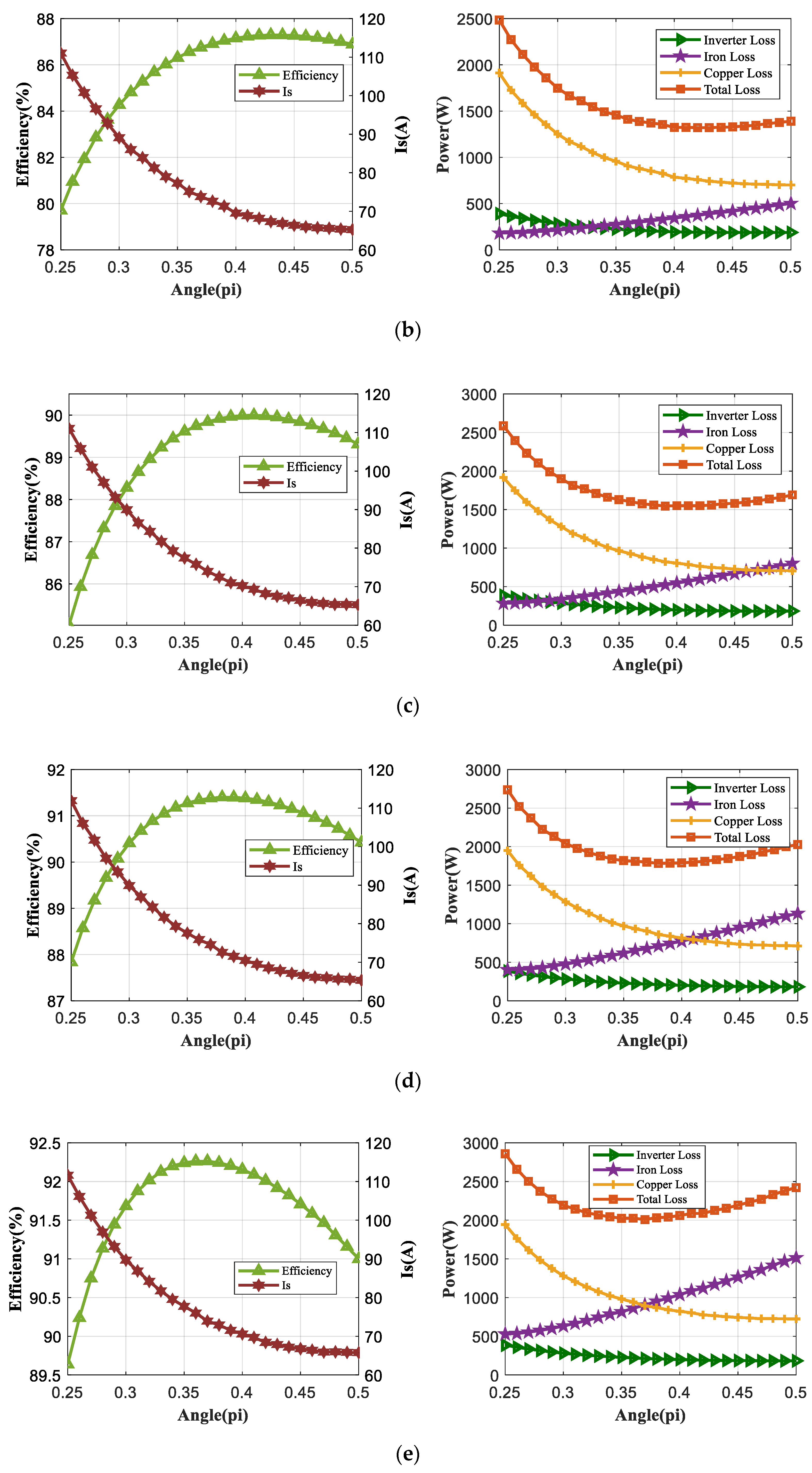
To study and verify the effectiveness of β on EDS efficiency optimization, five groups of EDS target working conditions were selected in this paper, namely 1000 rpm/50 Nm, 2000 rpm/50 Nm, 3000 rpm/50 Nm, 4000 rpm/50 Nm, and 5000 rpm/50 Nm, respectively. Then, by changing the value of input β from 0.25π to 0.5π gradually, PMSM controller will automatically control the EDS to reach the target working conditions. Subsequently, the EDS steady-state efficiency, stator current is, and various losses under different β were obtained, as shown in Figure 7.
The left side of Figure 7 shows the EDS efficiency and is change in different β. The left Y-axis represents the EDS efficiency, and the right Y-axis represents the stator current is. From the efficiency curve, it can be seen from the efficiency curve that the increase of is will not always reduce the EDS efficiency. This is because with the decrease of β and the increase of is, copper loss, iron loss, and inverter loss change nonlinearly. There is a trough in the sum of the three losses, which means that there will be a certain set of β and is to minimize the total loss of EDS. In other words, EDS has the highest efficiency at a certain set of β and is. This can be found in the right side of Figure 7a–e. As Figure 7a–e shows, as the working point of the motor moved from the region before the base speed to the region of flux weakening region continuously, the arc top of the efficiency curve was moved to the left continuously, and the optimal value of β decreased continuously.
It should be mentioned that in the region before the base speed, the change of β had a great influence on the EDS efficiency. For example, in Figure 7a, the efficiency was 66.81% when β = 0.25π while the highest efficiency was 80.03% when β = 0.47π, between which the difference was 13.22%. When the working point exceeded the base speed, with the increase of EDS speed, the effect of β on EDS efficiency became smaller, while there was still some optimization room. As shown in Figure 7, the efficiency was 89.64% when β = 0.25π while the efficiency was 92.26% when β = 0.36π, between which the difference was 2.62%.
It can be concluded from the above analysis that the change of β will significantly affect the efficiency of EDS. It is feasible to achieve the optimal control of the overall efficiency of EDS through β optimization.
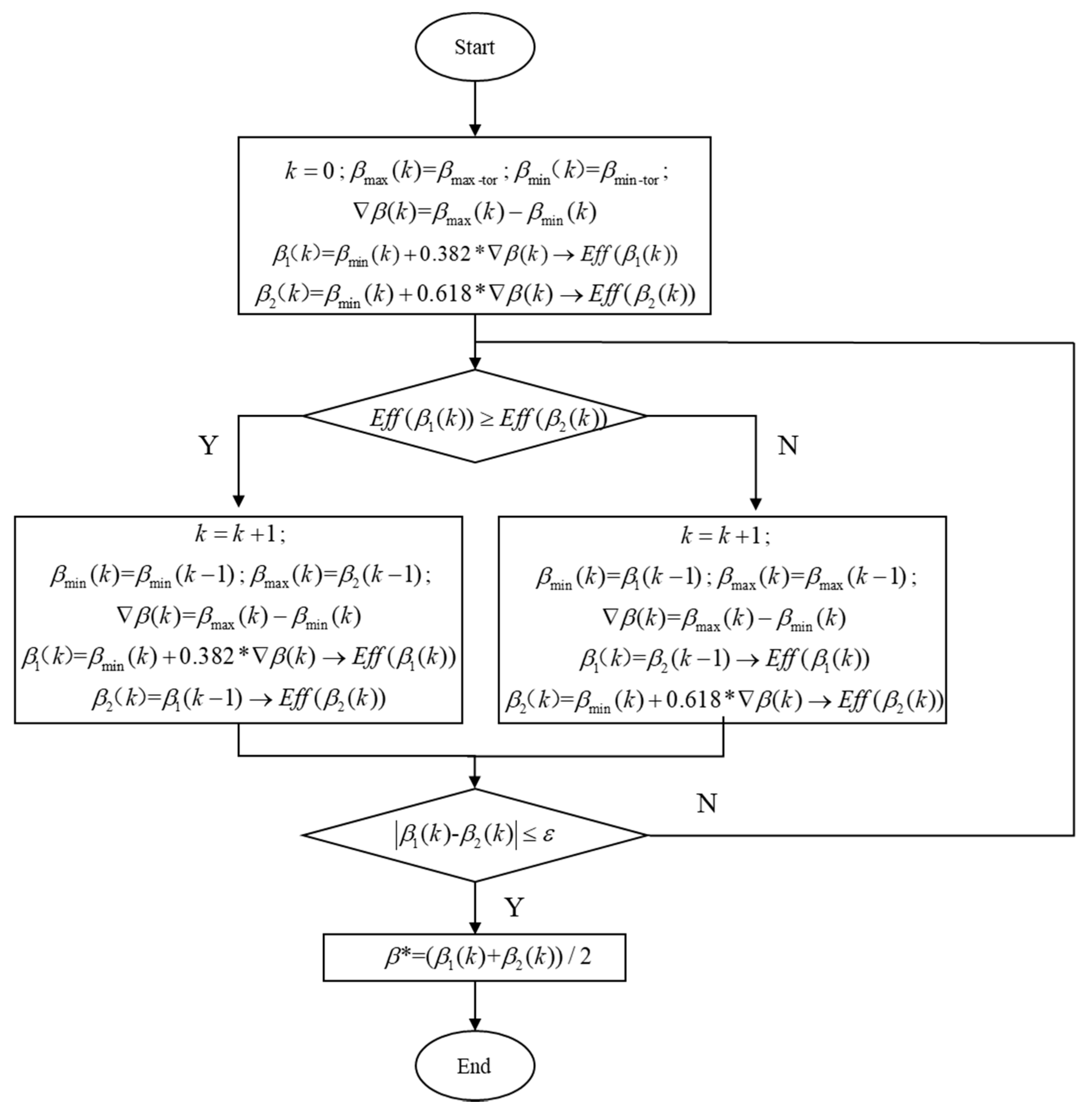
3.3. Current Angle Optimization Flow Based on Improved Golden Section Search Method
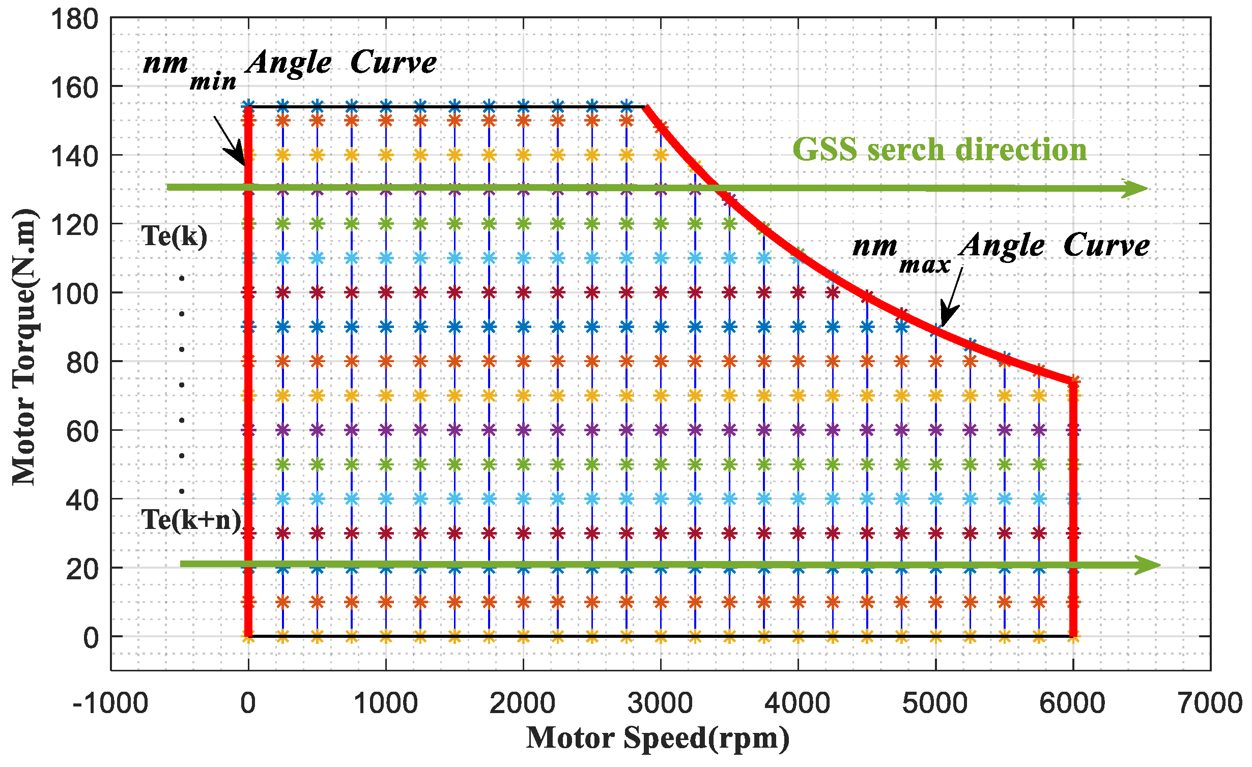
From the above results, it seems that the change rule of the optimal β is that when at the same load torque, the optimal β of the EDS efficiency decreases with the increase of the speed. Therefore, a large number of working points in the full operating range of EDS were analyzed in this paper to verify this rule, and the results proved that it was. Therefore, this paper proposes a β optimization method based on GSS, which can improve the speed of optimization and reduce the time to find the optimal set of β/is in the full operating range. Its process is as follows:
- According to the external characteristic diagram of the motor, select each working point on the red curve in Figure 8 as two groups of working conditions.
- Change the current angle, then the current angle curves βnm-min/βnm-max that ensure the efficiency of red curve maximum can be obtained and recorded in Te/nm-β/is look-up table so as to reduce the search area in GSS.
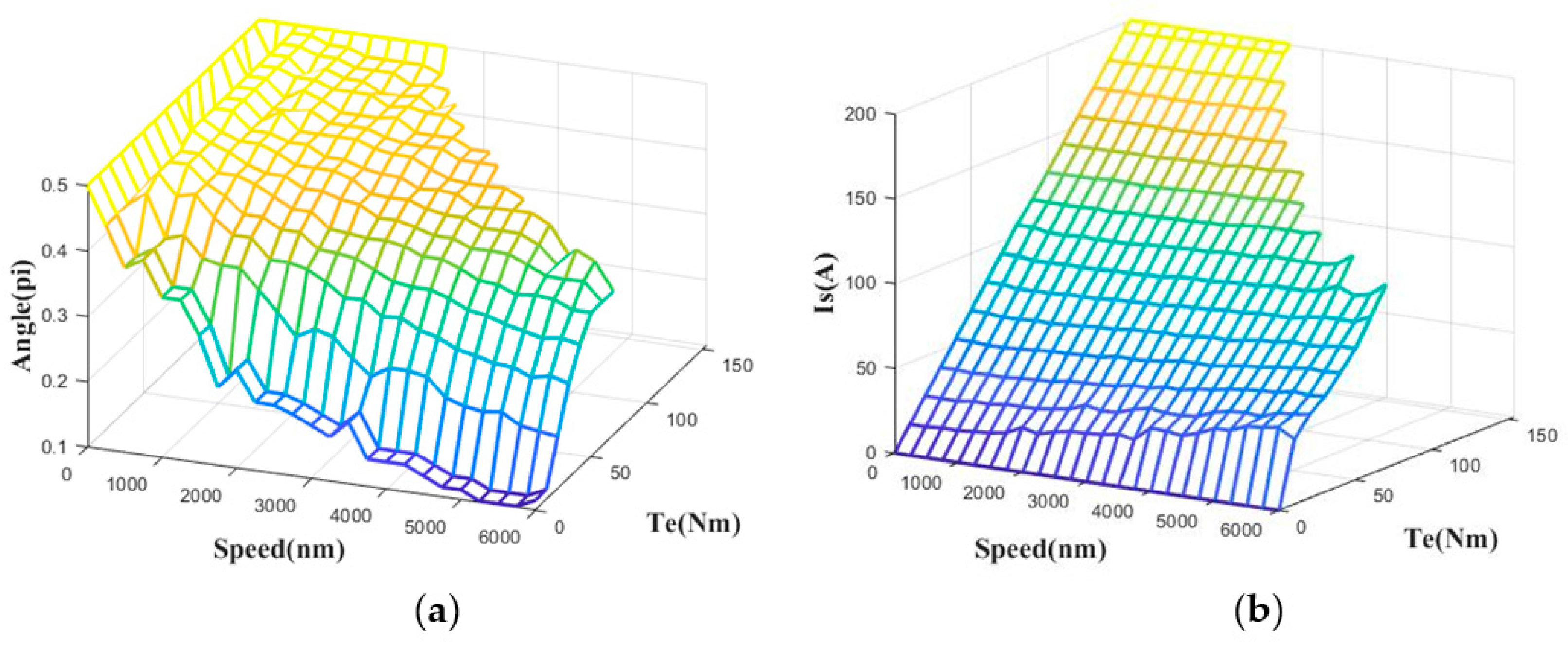
- Record the set of β/is corresponding to the maximum efficiency under whole working condition to Te/nm-β/is look-up table, which is illustrated in Figure 10.
Figure 10 shows the optimal current angle β and corresponding stator current is of EDS in the full working area. In Figure 10a, under the condition of low speed and high torque of the motor, the value of β is close to 0.5π. At this time, id was close to 0 A, which was close to the valve in MTPA (id = 0 A) control, but there was room for optimization obviously, which shows that the control strategy proposed in this paper had superiority over MTPA. Under the condition of low speed and low torque, the MTPA control could no longer meet the optimal efficiency, so the stator current is needed to be deflected to the left to increase β so as to increase the amplitude of id. When the motor entered the flux weakening region, optimal β continued to decrease while is continued to deflect to the left to meet the limit circle of voltage caused by the increased speed. In general, the optimal β decreased with the increase of motor speed and increased with the increase of motor torque. In Figure 10b, is increased with the increase of torque; meanwhile, there was a small increase when the speed increased. This is because the increase of speed will make the voltage limit circle of the motor narrow and is have to deflect to the left which will cause the increase of its amplitude, then the motor can meet the torque requirements. This can be seen in Figure 4.
3.4. Energy Optimization Control Strategy Based on Current Angle Look-Up Table
The effectiveness of current angle β for efficiency optimization control was verified and the optimal set of β/is in the whole working range was obtained. Based on that, the control strategy based on current angle β is proposed in this paper. The schematic diagram is illustrated in Figure 11.
Firstly, the actual speed of the motor was obtained by the encoder, and then the difference between the target speed and the actual speed was converted into the required torque according by the speed loop PI controller. Secondly, the Te/nm-β/is look-up table was searched online according to the required torque and the actual speed, and the target β and corresponding is were obtained. Finally, in the voltage command module, two voltage PID controllers were used to get the required control voltage Uα and Uβ. The SVPWM algorithm was used to get the voltage signal and then control the inverter and the motor, so that the motor can realize the specified work. It should be noted that the voltage feedback calculation module can increase the accuracy of the voltage signal.
4. Steady State and Transient State Simulation Validation
In order to fully verify the superiority of the control method proposed in this paper, based on the EDS loss model in Section 2, this section established the same two EDS models in MATLAB/Simulink environment. They were controlled by traditional MTPA with voltage feedback flux weakening control and proposed control strategy respectively and were simulated under the same working condition (including steady state and transient state). In the simulation, the MATLAB/Simulink version used in this paper is 2018b, and the computer processor is Intel(R) Core(TM) i5-6600 CPU@ 3.30Ghz. Ultimately the simulation results of steady state and transient acceleration process show the control strategy in this paper not only does not affect the performance of EDS, but also improves the steady state and transient state EDS efficiency.
4.1. Steady State Simulation Validation
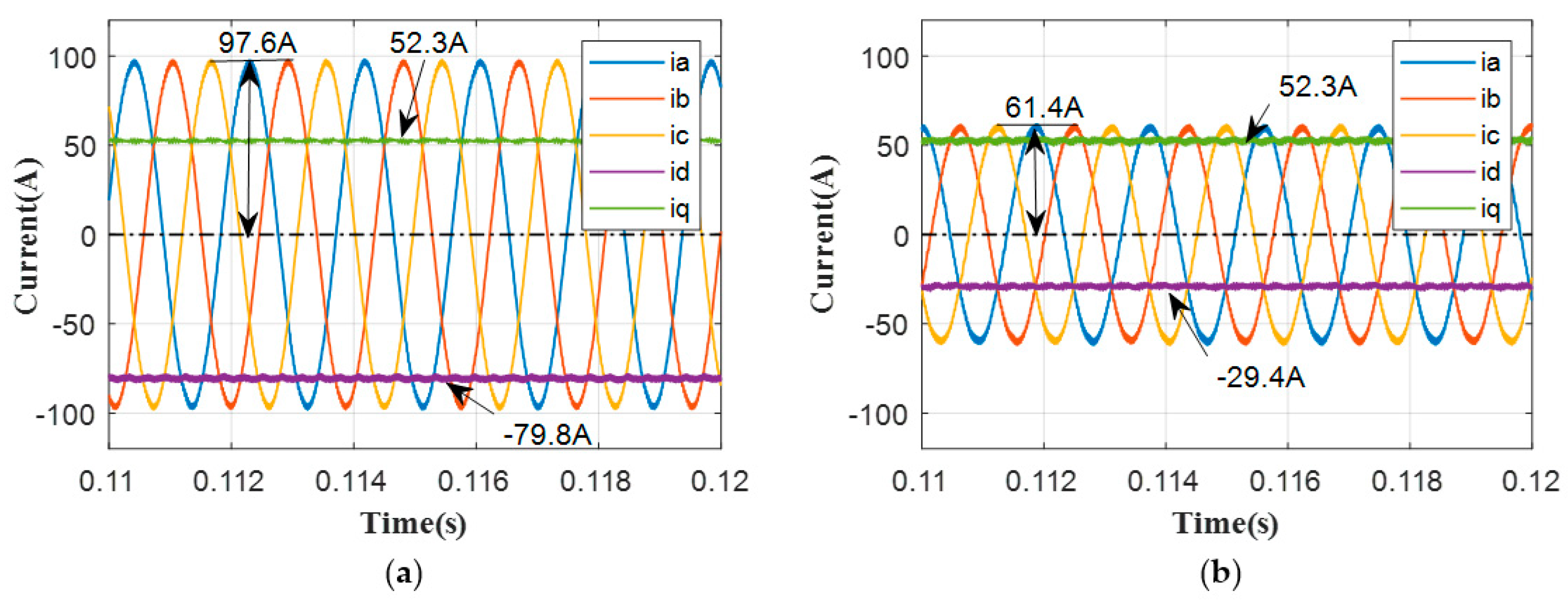
The target working conditions of the two controlled EDS were first set at 4000 rpm/40 Nm and then simulation was done in MATLAB/Simulink in this paper. When the EDS reached the target operating conditions and remained stable, the three-phase current ia/ib/ic and the dq-axis current id/iq of the two control strategies could be obtained under this steady state, as shown in Figure 12. The amplitude of ia/ib/ic before optimization was 97.6 A, which was 58.96% larger than 61.4 A after optimization. Furthermore, the id/iq before and after optimization was −79.8 A/52.3 A and −29.4 A/52.3 A, respectively, and at this time, β was 0.1847π and 0.3370π, respectively. It can be seen that the proposed control strategy in this paper can reduce id/iq of the motor by changing β. Consequently, it can reduce the power of EDS and improve the overall efficiency of EDS.
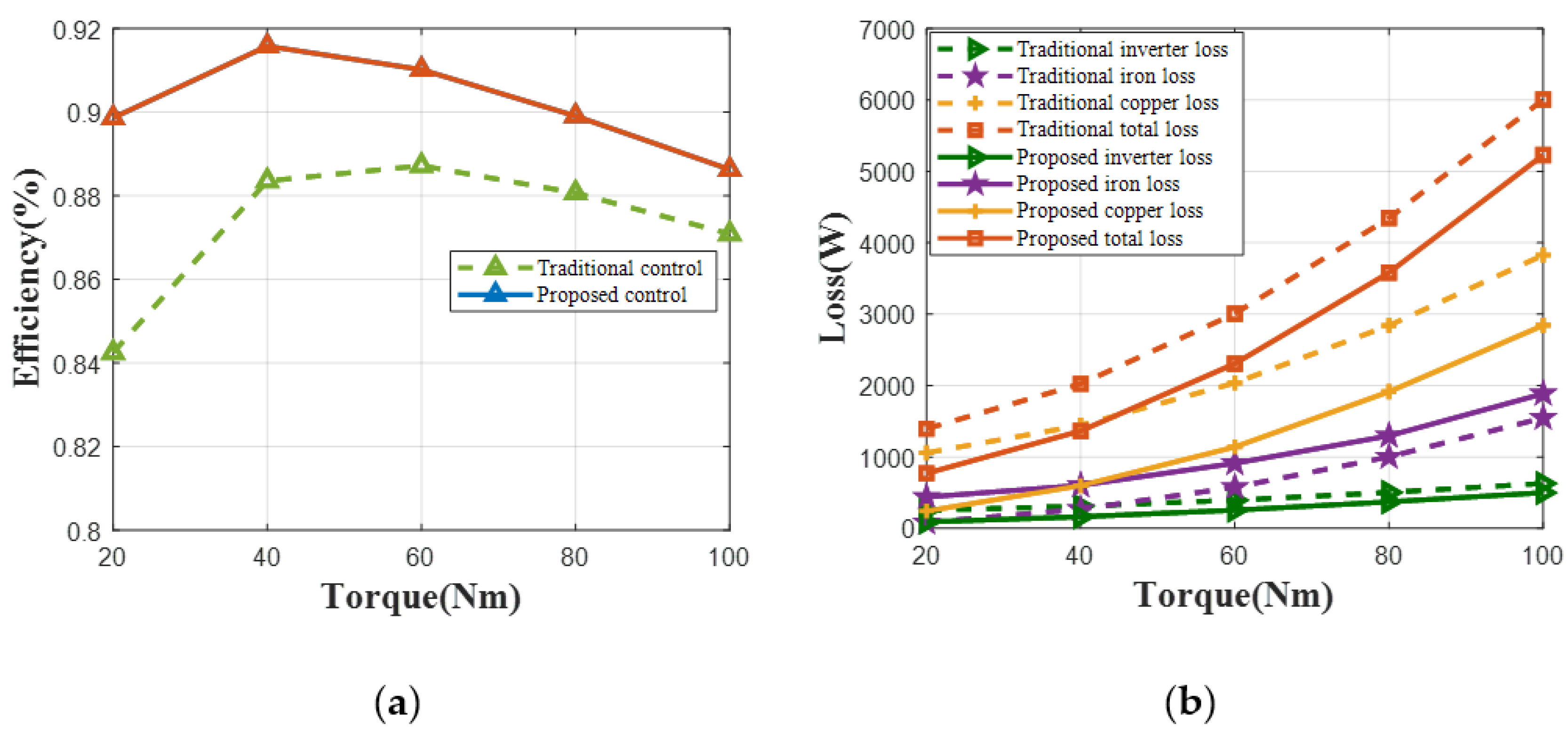
In addition, the constant speed-variable torque and constant torque-variable speed performance of the EDS are very important. Therefore, the working condition at 4000 rpm and variable torques and working condition at 40 Nm and variable speeds were simulated in this paper, in which the EDS efficiency, copper loss, iron loss, inverter loss, and overall loss of EDS controlled by traditional control and proposed control were studied respectively. The results are shown in Figure 13 and Figure 14. Figure 13 shows the comparison of EDS before and after optimization at 4000 rpm and variable torques while Figure 14 shows the comparison of EDS before and after optimization at 40 Nm and variable speeds.
In order to verify the superiority of the proposed control strategy in this paper compared with the traditional control strategy in the full working range, simulation of different steady-state conditions was carried out, and the results are shown in the Table 2. It can be seen that the inverter efficiency was always maintained at a high level, and its change contributed less to the change of EDS efficiency than that of the motor. However, it can be seen from the table that the optimization of overall EDS efficiency will be more accurate only when considering the inverter efficiency and motor efficiency together. As shown in Table 2, 2880 rpm was the base speed of the motor. Before this, the optimized value of EDS efficiency by the control strategy proposed in this paper was not high compared with the traditional MTPA control. This is because the traditional MTPA control has minimized the copper loss in the motor, which improves EDS efficiency to some extent. Despite all this, the control strategy proposed in this paper still improved the EDS efficiency by as much as 0.6% compared with the traditional control. When the motor enters into the flux weakening region, the optimized value becomes obvious. For instance, compared with the traditional control, the highest improvement of EDS efficiency by the proposed control occurred at 5000 rpm/40 Nm, reaching 5.9%.
Through the above results of steady state analysis, it can be concluded that the proposed control strategy can effectively improve the overall efficiency of EDS compared with the traditional control strategy.
4.2. Transient State Simulation Validation
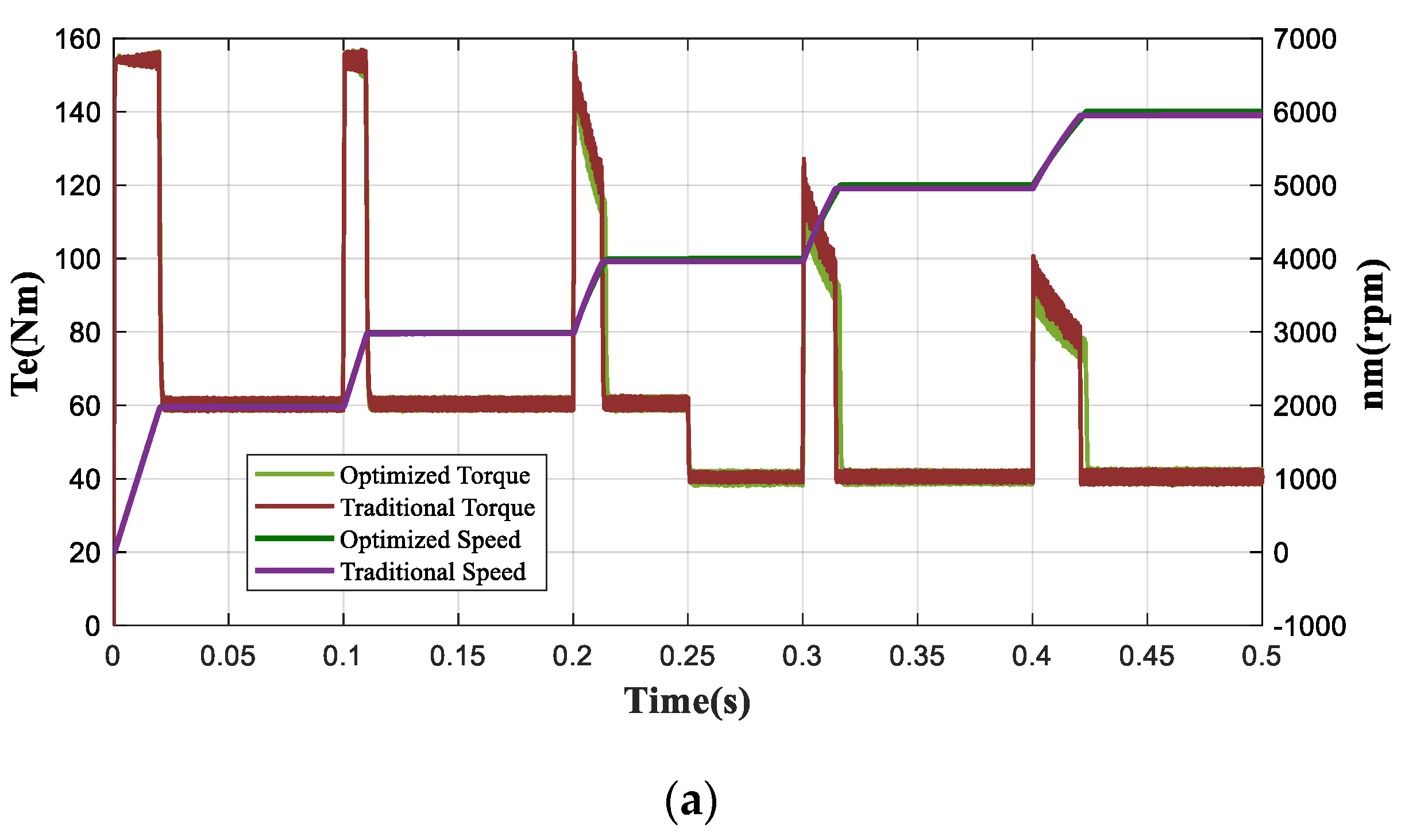
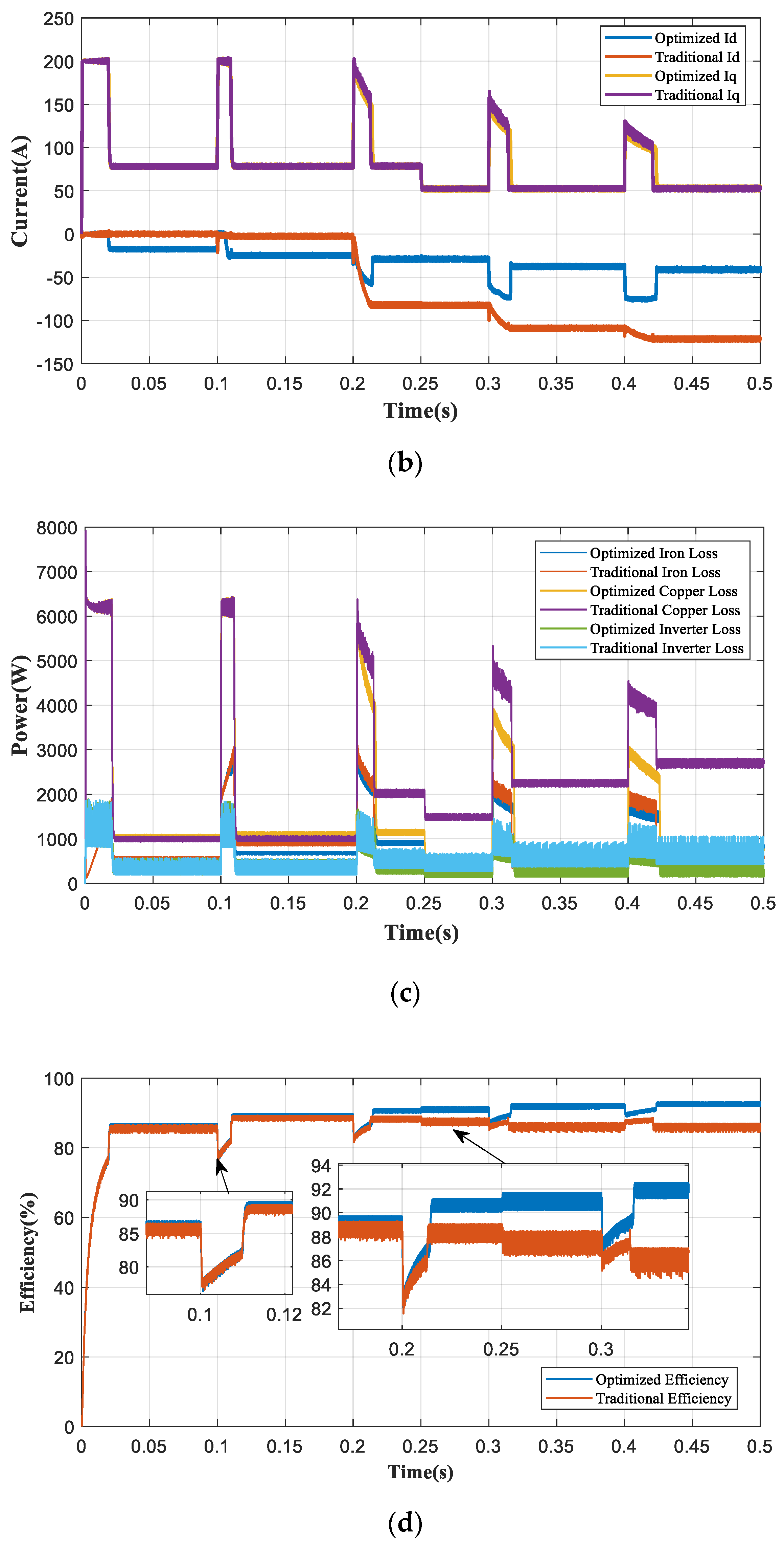
In reality, the working condition of EDS is complex and changeable and works in transient state at most times, so it is necessary to verify the transient performance of EDS. In order to verify the excellent performance of the proposed control strategy in the transient state, the transient simulation of EDS controlled by the proposed control strategy and EDS controlled by the traditional control strategy was carried out, respectively. The simulation time was 0.5 s and the time interval was 0.000001 s. In addition, the SVPWM modulation frequency fpwm (inverter switching frequency) was 20 kHz in the two EDS models. The target speed in 0 s–0.1 s, 0.1 s–0.2 s, 0.2 s–0.3 s, 0.3 s–0.4 s, and 0.4 s–0.5 s was set as 2000 rpm, 3000 rpm, 4000 rpm, 5000 rpm, and 6000 rpm, respectively, and the load before 0.25 s was set as 60 Nm while the load after 0.25 s was set as 40 Nm. The simulation results of EDS controlled by the traditional control strategy and EDS controlled by the proposed control strategy are shown in Figure 15, including torque, speed, dq-axis current id /iq various losses, and EDS efficiency.
In Figure 15a, the simulation results of the proposed control and the traditional control were almost the same, and the torque and speed curves of EDS before and after optimization almost overlapped, which showed that the proposed control strategy can ensure the power performance of EDS to achieve the same control effect as the traditional control strategy. In addition, when the EDS speed exceeded the base speed 2880 rpm, which meant the EDS entered into the flux weakening region, the optimized torque was slightly lower than the traditional control strategy in accelerating process, as shown in the last three torque peaks in Figure 15a. That is because traditional control only considered the limit of voltage limit circle and current limit circle, but ignored the limit of motor power, whereas proposed control in this paper considered the power limit of EDS, so its torque was slightly smaller than that of traditional control, which was more reasonable.
Figure 15b showed the difference between the proposed control strategy and the traditional control. The control strategy in this paper increased the negative value of id by changing the value of β and is before base speed region. For example, id was −17.6 A and −24.5 A at 2000 rpm/40 Nm and 3000 rpm/40 Nm, respectively, while those in traditional control were 0 A. On the other hand, after base speed region, namely in the flux weakening region, it not only met the driving demand, but also made the amplitude of id smaller and the loss of the EDS lower than the traditional one. In the case of 4000 rpm/60 Nm, 4000 rpm/40 Nm, 5000 rpm/40 Nm, and 6000 rpm/40 Nm steady states, id in proposed control were −29.5 A, −28.7 A, −37.2 A, and −41 A, respectively, while those in traditional control were −82.3 A, −83.5 A, −108.7 A, and −121.5 A, respectively.
As shown in Figure 15c–d, copper loss accounts for most of the EDS loss, so the EDS efficiency was more affected by the change of copper loss. Before 0.2 s, the optimization of current vector traditional MTPA and FW control was enough, and the optimization of the control strategy proposed in this paper mainly came from iron loss and inverter loss. At this time, the efficiency optimization of EDS was from 86.2% of the traditional control efficiency to 86.6% at 2000 rpm/60 Nm, and from 88.6% to 89.2% at 3000 rpm/60 Nm. After 0.2 s, the control strategy proposed in this paper obviously changed the current vector. In Figure 15c, it can be seen that all kinds of losses of EDS have been greatly reduced, which showed that under the conditions of 4000 rpm/60 Nm, 4000 rpm/40 Nm, 5000 rpm/40 Nm, and 6000 rpm/40 Nm, the efficiency of EDS had increased from 88.5%, 87.7%, 86.5%, 86.2% to 90.7%, 91.3%, 92.4%, 92.7%, respectively. From the whole transient process, when the EDS speed did not exceed the base speed between 0–0.2 s, the efficiency of EDS under the control strategy in this paper was slightly higher than that of MTPA. After 0.2 s, the EDS speed exceeded the base speed, and the optimization value of EDS efficiency of this strategy gradually increased. When the motor was stable to 6000 rpm/40 Nm, it reached the maximum value. The highest value was 92.7%, which is 6.5% higher than 86.2% of the traditional control. Specific efficiency comparison is illustrated in Table 3.
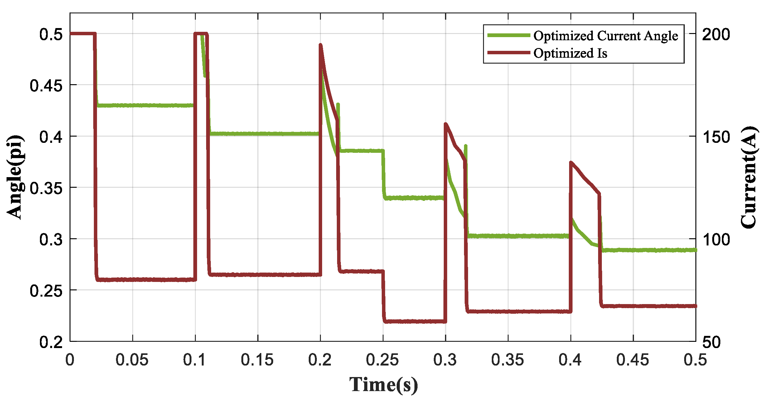
Figure 16 shows the β and is got by the proposed control in this paper during this transient process. It can be found that in region before the base speed, β and is constantly changed to meet the optimal EDS efficiency. When the motor speed exceeded the base speed, β and is obtained according to the current speed and torque demand of the EDS were gradually reduced, then they remained unchanged when the motor worked stably.
5. Conclusions
In this paper, the model of PMSM electric drive system considering the copper loss, iron loss, and inverter loss was established. The effectiveness of a special control variable current angle β on EDS efficiency optimization was studied and verified and its general influence law on EDS efficiency was studied. On this basis, GSS was used to reduce the calculation of the optimal β and a novel energy optimization control strategy based on current angle β was proposed, which control current angle β and stator current is according to the operating speed and the load conditions to improve the EDS efficiency at the whole operation condition. The following two points should be noted:
- Optimizing β helps to improve EDS efficiency. The general influence law of β on EDS efficiency is that change of β has a great influence on the EDS efficiency under the working condition before the base speed, but less influence on the EDS efficiency in the flux weakening region. Furthermore, the optimal β of PMSM in this paper decreases with the increase of motor speed while increases with the increase of motor torque.
- Compared with the traditional control strategy, the steady state simulation results showed that the proposed control strategy can improve the efficiency of EDS in the whole working area. The EDS efficiency increased 0.6% at 1000 rpm/60 Nm, 5.9% at 5000 rpm/40 Nm, and 6.5% at 6000 rpm/40 Nm. The transient simulation results of periodic acceleration (2000 rpm to 6000 rpm) and variable load (60 Nm to 40 Nm) showed that the proposed control strategy can not only achieve stable operation and fast response of EDS, but also ensure that the EDS efficiency in the transient process is always higher than that the traditional control.
Author Contributions
Conceptualization: J.H.; data curation: M.J. and Y.G.; funding acquisition: J.H. and T.P.; investigation: M.J.; methodology: J.H. and Y.Y.; project administration: J.H.; software: Y.Y.; validation: Y.G.; visualization: Y.Y.; writing—original draft: J.H., Y.Y., and T.P. All authors have read and agreed to the published version of the manuscript.
Funding
This research was funded by the Key Technological Innovation Research and Development Project of Chongqing under Grant No. cstc2018jszx-cyztzx0047 and the National Key Research and Development Program of China under Grant No. 2018YFB0106100.
Conflicts of Interest
The authors declare no conflict of interest.
References
- Emadi, A.; Lee, Y.J.; Rajashekara, K. Power electronics and motor drives in electric, hybrid electric, and plug-in hybrid electric vehicles. IEEE Trans. Ind. Electron. 2008, 55, 2237–2245. [Google Scholar] [CrossRef]
- Rajashekara, K. Present Status and Future Trends in Electric Vehicle Propulsion Technologies. IEEE J. Emerg. Sel. Top. Power Electron. 2013, 1, 3–10. [Google Scholar] [CrossRef]
- Dmitrievskii, V.; Prakht, V.; Kazakbaev, V.; Sarapulov, S. Optimal Design of a High-Speed Single-Phase Flux Reversal Motor for Vacuum Cleaners. Energies 2018, 11, 3334. [Google Scholar] [CrossRef] [Green Version]
- Cui, J.; Xiao, W.; Wang, L.; Feng, H.; Zhao, J.; Wang, H. Optimization design of low-speed surface-mounted PMSM for pumping unit. Int. J. Appl. Electromagn. Mech. 2014, 46, 217–228. [Google Scholar] [CrossRef]
- Cho, S.; Ahn, H.; Ham, H.S.; Jin, S.C.; Lee, G.S.; Lee, J. Design of Fan-shape Type PMSM for Improving Efficiency of Non-rare Earth Motor. Trans. Korean. Inst. Electr. Eng. 2016, 65, 360–364. [Google Scholar]
- Liu, X.; Lin, Q.; Fu, W. Optimal Design of Permanent Magnet Arrangement in Synchronous Motors. Energies 2017, 10, 1700. [Google Scholar] [CrossRef] [Green Version]
- Hu, J.; Zheng, L.; Jia, M.; Zhang, Y.; Pang, T. Optimization and Model Validation of Operation Control Strategies for a Novel Dual-Motor Coupling-Propulsion Pure Electric Vehicle. Energies 2018, 11, 754. [Google Scholar] [CrossRef] [Green Version]
- Ruan, J.; Song, Q. A Novel Dual-Motor Two-Speed Direct Drive Battery Electric Vehicle Drivetrain. IEEE Access 2019, 7, 54330–54342. [Google Scholar] [CrossRef]
- Gao, B.; Liang, Q.; Xiang, Y.; Guo, L.; Chen, H. Gear ratio optimization and shift control of 2-speed I-AMT in electric vehicle. Mech. Syst. Signal. Process. 2015, 50-51, 615–631. [Google Scholar] [CrossRef]
- Bose, B.K.; Patel, N.R.; Rajashekara, K. A neuro-fuzzy-based on-line efficiency optimization control of a stator flux-oriented direct vector-controlled induction motor drive. IEEE Trans. Ind. Electron. 1997, 44, 270–273. [Google Scholar] [CrossRef]
- Ta, C.M.; Hori, Y. Convergence improvement of efficiency-optimization control of induction motor drives. IEEE Trans. Ind. Appl. 2001, 37, 1746–1753. [Google Scholar]
- Zhao, J.; Hua, M.; Liu, T. Research on a Sliding Mode Vector Control System Based on Collaborative Optimization of an Axial Flux Permanent Magnet Synchronous Motor for an Electric Vehicle. Energies 2018, 11, 3116. [Google Scholar] [CrossRef] [Green Version]
- Cavallaro, C.; Di Tommaso, A.O.; Miceli, R.; Raciti, A.; Galluzzo, G.R.; Trapanese, M. Efficiency enhancement of permanent-magnet synchronous motor drives by online loss minimization approaches. IEEE Trans. Ind. Electron. 2005, 52, 1153–1160. [Google Scholar] [CrossRef] [Green Version]
- Morimoto, S.; Tong, Y.; Takeda, Y.; Hirasa, T. Loss Minimization Control of Permanent-Magnet Synchronous Motor-Drives. IEEE Trans. Ind. Electron. 1994, 41, 511–517. [Google Scholar] [CrossRef]
- Lee, J.; Nam, K.; Choi, S.; Kwon, S. Loss-Minimizing Control of PMSM With the Use of Polynomial Approximations. IEEE Trans. Power Electron. 2009, 24, 1071–1082. [Google Scholar]
- Rabiei, A.; Thiringer, T.; Lindberg, J. Maximizing the Energy Efficiency of a PMSM for Vehicular Applications Using an Iron Loss Accounting Optimization Based on Nonlinear Programming. In Proceedings of the 2012 XXth International Conference on Electrical Machines, Marseille, France, 2–5 September 2012; pp. 1001–1007. [Google Scholar]
- Prabhakar, K.K.; Chinthakunta, U.R.; Singh, A.K.; Kumar, P. Efficiency and performance analysis of DTC-based IM drivetrain using variable dc-link voltage for electric vehicle applications. IET Electr. Syst. Transport. 2018, 8, 205–214. [Google Scholar] [CrossRef]
- Deng, W.; Zhao, Y.; Wu, J. Energy Efficiency Improvement via Bus Voltage Control of Inverter for Electric Vehicles. IEEE Trans. Veh. Technol. 2017, 66, 1063–1073. [Google Scholar] [CrossRef]
- Andersson, A.; Thiringer, T. IEEE Inverter Losses Minimization Using Variable Switching Frequency Based On Multi-objective Optimization. In Proceedings of the 2014 International Conference on Electrical Machines (ICEM), Berlin, Germany, 2–5 September 2014; pp. 789–795. [Google Scholar]
- Sruthi, M.P.; Nagamani, C.; Ilango, G.S. An improved algorithm for direct computation of optimal voltage and frequency for induction motors. Eng. Sci. Technol. Int. J. 2017, 20, 1439–1449. [Google Scholar] [CrossRef]
- Khoury, G.; Ghosn, R.; Khatounian, F.; Fadel, M.; Tientcheu, M. An energy-efficient scalar control taking core losses into account. Int. J. Comput. Math. Electr. Electr. Eng. 2018, 37, 849–867. [Google Scholar] [CrossRef]
- Choudhary, P.K.; Dubey, S.P. Energy efficient operation of induction motor drives: Economic and environmental analysis in cement manufacturing. Environ. Prog. Sustain. Energ. 2019, 38, 672–679. [Google Scholar] [CrossRef]
- Ding, X.; Guo, H.; Xiong, R.; Chen, F.; Zhang, D.; Gerada, C. A new strategy of efficiency enhancement for traction systems in electric vehicles. Appl. Energ. 2017, 205, 880–891. [Google Scholar] [CrossRef]
- Guo, Q.; Zhang, C.; Li, L.; Gerada, D.; Zhang, J.; Wang, M. Design and implementation of a loss optimization control for electric vehicle in-wheel permanent-magnet synchronous motor direct drive system. Appl. Energ. 2017, 204, 1317–1332. [Google Scholar] [CrossRef]
- Cui, Y.; Zhang, W.; Tolbert, L.M.; Costinett, D.J.; Wang, F.; Blalock, B.J. Two Phase Interleaved ISOP Connected High Step Down Ratio Phase Shift Full Bridge DC/DC Converter with GaN FETs. In Proceedings of the 2015 Thirtieth Annual IEEE Applied Power Electronics Conference and Exposition, Charlotte, NC, USA, 15–19 March 2015; pp. 1414–1419. [Google Scholar]
- Michal, V. Three-Level PWM Floating H-Bridge Sinewave Power Inverter for High-Voltage and High-Efficiency Applications. IEEE Trans. Power Electron. 2016, 31, 4065–4074. [Google Scholar] [CrossRef]
- Wang, Z.Q.; Cui, F.Y.; Zhang, G.Z.; Shi, T.N.; Xia, C.L. Novel Carrier-Based PWM Strategy with Zero-Sequence Voltage Injected for Three-Level NPC Inverter. IEEE J. Emerg. Sel. Topics Power Electron. 2016, 4, 1442–1451. [Google Scholar] [CrossRef]
- Tam-Khanh Tu, N.; Nho-Van, N.; Prasad, N.R. Novel Eliminated Common-Mode Voltage PWM Sequences and an Online Algorithm to Reduce Current Ripple for a Three-Level Inverter. IEEE Trans. Power Electron. 2017, 32, 7482–7493. [Google Scholar]
- Eduardo Quintal-Palomo, R.; Gwozdziewicz, M.; Dybkowski, M. Modelling and co-simulation of a permanent magnet synchronous generator. Int. J. Comput. Math. Electr. Electr. Eng. 2019, 38, 1904–1917. [Google Scholar] [CrossRef]
- Gu, J.; Ouyang, M.; Lu, D.; Li, J.; Lu, L. Energy Efficiency Optimization of Electric Vehicle Driven by In-Wheel Motors. Int. J. Auto. Tech. 2013, 14, 763–772. [Google Scholar] [CrossRef]
- Fernandez-Bernal, F.; Garcia-Cerrada, A.; Faure, R. Determination of parameters in interior permanent-magnet synchronous motors with iron losses without torque measurement. Ieee Trans. Ind. Appl. 2001, 37, 1265–1272. [Google Scholar] [CrossRef]
- Kolar, J.W.; Zach, F.C. Losses in PWM Inverters using IGBTS. IEE P.-Electr. Power Appl. 1995, 142, 285–288. [Google Scholar] [CrossRef]
- Sun, T.; Kwon, S.-O.; Lee, J.-J.; Hong, J.-P. Investigation and Comparison of System Efficiency on the PMSM Considering Nd-Fe-B Magnet and Ferrite Magnet. In Proceedings of the Intelec 09–31st International Telecommunications Energy Conference, Incheon, South Korea, 18–22 October 2009; pp. 181–186. [Google Scholar]
- 6MBI100VX-120-50 Datasheet–Fuji Electric. Available online: https://www.alldatasheet.com/datasheet-pdf/pdf/463685/FUJI/6MBI100VX-120-50.html (accessed on 6 June 2019).
- Abdelrahem, M.; Hackl, C.M.; Kennel, R. Implementation and experimental investigation of a sensorless field-oriented control scheme for permanent-magnet synchronous generators. Electr. Eng. 2018, 100, 849–856. [Google Scholar] [CrossRef]
- Wang, F.X.; Zhang, Z.B.; Mei, X.Z.; Rodriguez, J.; Kennel, R. Advanced Control Strategies of Induction Machine: Field Oriented Control, Direct Torque Control and Model Predictive Control. Energies 2018, 11, 120. [Google Scholar] [CrossRef] [Green Version]
- Deng, T.; Su, Z.; Li, J.; Tang, P.; Chen, X.; Liu, P. Advanced Angle Field Weakening Control Strategy of Permanent Magnet Synchronous Motor. IEEE Trans. Veh. Tech. 2019, 68, 3424–3435. [Google Scholar] [CrossRef]
Figure 1.
Schematic of general electric drive system.

Figure 2.
Equivalent circuit schematic of PMSM: d-axis equivalent circuit (a); q-axis equivalent circuit (b).
Figure 2.
Equivalent circuit schematic of PMSM: d-axis equivalent circuit (a); q-axis equivalent circuit (b).

Figure 3.
Typical IGBT module working process.

Figure 4.
Relationship of collector current and collector-emitter voltage between IGBT and FWD.

Figure 5.
Schematic of PMSM stator current action.

Figure 6.
Schematic diagram of current angle β optimization model proposed in this paper.

Figure 7.
Efficiency, is, and various losses of EDS under different β at 1000 rpm/50 Nm (a); efficiency, is, and various losses of EDS under different β at 2000 rpm/50 Nm (b); efficiency, is, and various losses of EDS under different β at 3000 rpm/50 Nm (c); efficiency, is, and various losses of EDS under different β at 4000 rpm/50 Nm (d); efficiency, is, and various losses of EDS under different β at 5000 rpm/50 Nm (e).


Figure 8.
Schematic diagram chart of current angle β optimization.

Figure 9.
Schematic diagram of golden section search method.

Figure 10.
Optimal β and is three-dimensional look-up table under whole working condition: Optimal current angle β (a); corresponding stator current is (b).
Figure 10.
Optimal β and is three-dimensional look-up table under whole working condition: Optimal current angle β (a); corresponding stator current is (b).

Figure 11.
Schematic diagram of proposed control in this paper.

Figure 12.
Current comparison between traditional control and proposed control at 4000 rpm/40 Nm: Traditional control current diagram (a); proposed control current diagram (b).
Figure 12.
Current comparison between traditional control and proposed control at 4000 rpm/40 Nm: Traditional control current diagram (a); proposed control current diagram (b).

Figure 13.
Comparison of EDS efficiency (a) and various losses (b) between traditional control and proposed control at 400 rpm and variable torques.
Figure 13.
Comparison of EDS efficiency (a) and various losses (b) between traditional control and proposed control at 400 rpm and variable torques.

Figure 14.
Comparison of EDS efficiency (a) and various losses (b) between traditional control and proposed control at 40 Nm and variable speeds.
Figure 14.
Comparison of EDS efficiency (a) and various losses (b) between traditional control and proposed control at 40 Nm and variable speeds.

Figure 15.
Comparison of transient state performance between proposed control and traditional control: The comparison of torque and speed between two controls (a); the comparison of id and iq between two controls (b); the comparison of different loss between two controls (c); the comparison of efficiency of EDS between two controls (d).


Figure 16.
Change chart of β and is in proposed control strategy at transient process.


Table 1.
Permanent magnet synchronous motor (PMSM) parameters in this paper.
| Parameter | Value |
|---|---|
| Peak power | 46.5 KW |
| Rated speed | 2880 rpm |
| Peak torque | 154.2 Nm |
| Pole number | 4 |
| Rated voltage | 600 V |
| Peak current | 200 A |
| Rotor flux linkage | 0.0642 Wb |
| dq-axis inductance | 7.0743 × 10⁻⁴ H |
Table 2.
Efficiency of traditional control strategy and proposed control strategy under different steady state conditions.
Table 2.
Efficiency of traditional control strategy and proposed control strategy under different steady state conditions.
| Traditional Control Strategy | |||||
|---|---|---|---|---|---|
| Speed (rpm) | Torque (Nm) | Inverter Efficiency (%) | Motor Efficiency (%) | EDS Efficiency (%) | |
| 1000 | 120 | 96.3 | 72.2 | 69.5 | |
| 1000 | 60 | 97.0 | 80.8 | 78.4 | |
| 2000 | 120 | 98.0 | 82.4 | 80.7 | |
| 2000 | 60 | 98.4 | 87.6 | 86.2 | |
| 2850 | 120 | 98.0 | 80.8 | 78.6 | |
| 2850 | 60 | 98.9 | 89.7 | 88.6 | |
| 3000 | 100 | 98.7 | 87.6 | 86.4 | |
| 3000 | 50 | 99.0 | 90.3 | 89.4 | |
| 4000 | 80 | 98.7 | 89.2 | 88.1 | |
| 4000 | 40 | 98.4 | 89.1 | 87.7 | |
| 5000 | 80 | 98.7 | 87.8 | 86.4 | |
| 5000 | 40 | 98.2 | 88.1 | 86.5 | |
| 6000 | 60 | 98.8 | 88.5 | 86.5 | |
| 6000 | 30 | 97.9 | 87.9 | 86.1 | |
| Proposed Control Strategy | |||||
| Speed (rpm) | Torque (Nm) | Inverter Efficiency (%) | Motor Efficiency (%) | EDS Efficiency (%) | EDS Efficiency Improvement (%) |
| 1000 | 120 | 96.4 | 72.5 | 69.8 | 0.3 |
| 1000 | 60 | 96.9 | 81.0 | 78.6 | 0.2 |
| 2000 | 120 | 97.9 | 82.6 | 80.9 | 0.2 |
| 2000 | 60 | 98.3 | 88.0 | 86.6 | 0.4 |
| 2880 | 120 | 98.0 | 80.8 | 78.6 | 0 |
| 2880 | 60 | 98.8 | 90.3 | 89.2 | 0.6 |
| 3000 | 100 | 98.7 | 87.8 | 86.7 | 0.3 |
| 3000 | 50 | 98.9 | 91.0 | 90.0 | 0.6 |
| 4000 | 80 | 99.0 | 90.8 | 89.0 | 0.9 |
| 4000 | 40 | 99.1 | 92.1 | 91.3 | 3.6 |
| 5000 | 80 | 98.9 | 88.9 | 87.6 | 1.2 |
| 5000 | 40 | 99.2 | 93.1 | 92.4 | 5.9 |
| 6000 | 60 | 99.0 | 90.3 | 89.1 | 2.6 |
| 6000 | 30 | 99.2 | 92.0 | 91.0 | 4.9 |
Table 3.
Efficiency comparison chart of transient process at different time.
| Time (s) | Traditional Control Efficiency (%) | Proposed Control Efficiency (%) | Efficiency Improvement (%) |
|---|---|---|---|
| 0.05 | 86.2 | 86.6 | 0.3 |
| 0.105 | 80.3 | 80.3 | 0 |
| 0.15 | 82.0 | 82.4 | 0.4 |
| 0.21 | 86.6 | 85.4 | 1.2 |
| 0.25 | 88.7 | 91.0 | 2.3 |
| 0.31 | 87.5 | 89.1 | 1.6 |
| 0.35 | 86.5 | 92.4 | 5.9 |
| 0.41 | 88.0 | 90.5 | 2.5 |
| 0.45 | 86.2 | 92.7 | 6.5 |
| 0.5 | 86.2 | 92.7 | 6.5 |
© 2020 by the authors. Licensee MDPI, Basel, Switzerland. This article is an open access article distributed under the terms and conditions of the Creative Commons Attribution (CC BY) license (http://creativecommons.org/licenses/by/4.0/).
Share and Cite
MDPI and ACS Style
Hu, J.; Yang, Y.; Jia, M.; Guan, Y.; Peng, T. A Novel Energy Optimization Control Strategy for Electric Drive System Based on Current Angle. Appl. Sci. 2020, 10, 3778. https://doi.org/10.3390/app10113778
AMA Style
Hu J, Yang Y, Jia M, Guan Y, Peng T. A Novel Energy Optimization Control Strategy for Electric Drive System Based on Current Angle. Applied Sciences. 2020; 10(11):3778. https://doi.org/10.3390/app10113778
Chicago/Turabian StyleHu, Jianjun, Ying Yang, Meixia Jia, Yongjie Guan, and Tao Peng. 2020. "A Novel Energy Optimization Control Strategy for Electric Drive System Based on Current Angle" Applied Sciences 10, no. 11: 3778. https://doi.org/10.3390/app10113778
Note that from the first issue of 2016, this journal uses article numbers instead of page numbers. See further details here.