Resonance-Driven Passive Folding/Unfolding Flapping Wing Actuator


Toyota Central R&D Labs. Inc., Aichi 480-1192, Japan
*
Author to whom correspondence should be addressed.
Appl. Sci. 2020, 10(11), 3771; https://doi.org/10.3390/app10113771
Submission received: 16 April 2020
/
Revised: 19 May 2020
/
Accepted: 28 May 2020
/
Published: 29 May 2020
(This article belongs to the Special Issue Biomimetic Sensors and Actuators)
Abstract
:The wings of flapping-wing micro aerial vehicles (MAVs) face the risk of breakage. To solve this issue, we propose the use of a biomimetic foldable wing. In this study, a resonant-driven piezoelectric flapping-wing actuator with a passive folding/unfolding mechanism was designed and fabricated, in which the folding/unfolding motion is passively realized by the centrifugal and lift forces due to the stroke motion of the wings. Although the passive folding/unfolding is a known concept, its feasibility and characteristics in combination with a resonant system have not yet been reported. Because the resonant actuation is necessary for extremely small, insect-scale MAVs, research is required to realize such MAVs with a foldable-wing mechanism. Therefore, we first examine and report the performance of the resonant-driven passive folding/unfolding mechanism. We also present a simplified theoretical model demonstrating an interaction between the resonant actuation system and folding/unfolding mechanism. We successfully demonstrate the folding/unfolding motion by the fabricated actuator. In addition, the theoretical model showed good agreement with the experiment.
1. Introduction
In recent years, bioinspired flapping-wing micro aerial vehicles (FWMAVs) have attracted considerable attention owing to their wide application fields, such as for use in rescue missions, inspection of building structures, and remote sensing. In addition, their flight performance has also gained interest because it could be inherent to the flying ability of natural birds and insects. One of the concerns of the FWMAVs compared to the prevalent multirotor systems is the robustness of their wings. As the wing is lighter and a larger structure than a rotor, it is liable to be fragile. Although natural birds and insects should also face the same problem, their wings are foldable, and thus the breakage risk by collision is decreased.
Bioinspired foldable wings have been reportedly developed by several research groups. Muhammad et al. [1] and Nguyen et al. [2] researched on beetle-inspired foldable wings driven by a shape memory alloy actuator. Ma et al. [3] reported on a bat-like wing with a motorized folding/unfolding system. In the case of a fixed but not a flapping wing, Siddall et al. [4] and Luca et al. [5] presented foldable wings actuated by motorized systems. Stowers et al. [6] reported on the use of a passive folding/unfolding system in a motor-driven foldable wing, and demonstrated the actuation of the folding/unfolding motion mainly by the centrifugal force, associated with the flapping motion of the wing. Because this passive folding/unfolding system does not require additional actuation devices, it is considered to have advantages of being lightweight and consuming less power. We consider these advantages to be suitable for MAV applications, and thus employed the passive folding/unfolding wing system in the current study.
Stowers and Lentink [6] proposed a bat-scaled wing system. Whether this concept is applicable to insect-scaled FWMAVs still needs to be ascertained. In their report, the wing-flapping motion was forcibly defined by a motorized system. However, in an insect-scaled FWMAV, the wing motion is generally actuated by resonance [7,8,9,10]; the stroke amplitude of the wing is amplified by matching the resonant frequency of the system with the actuation force. We expect the passive folding/unfolding wing system and resonant flapping actuation system to interact with each other, and this could play an important role in the folding/unfolding characteristics. To the best of the authors’ knowledge, this possible interaction phenomenon has not yet been studied.
In this paper, we report on the theoretical modelling and experimental demonstration of the passive folding/unfolding wing system with a resonant-driven actuator. The contributions of this study are summarized as follows:
- -
- We provide a simplified system model with experimental validation.
- -
- The system is observed to show bistability, and the stable region shifts because of the actuation frequency and voltage (torque).
- -
- We propose a method to enlarge the stable region, in which the frequency and voltage are simultaneously modulated. This contributes to the extension of the variable range of the lift force.
In Section 2, we describe the structure of the actuator and the experimental method. Section 3 is devoted to the simplified theoretical modelling. The experimental results and discussion based on a comparison between the experiment and theory are reported in Section 4. Finally, the conclusions of this study are drawn in Section 5.
2. Structure and Modelling
2.1. Structure of the Flapping-Wing Actuator
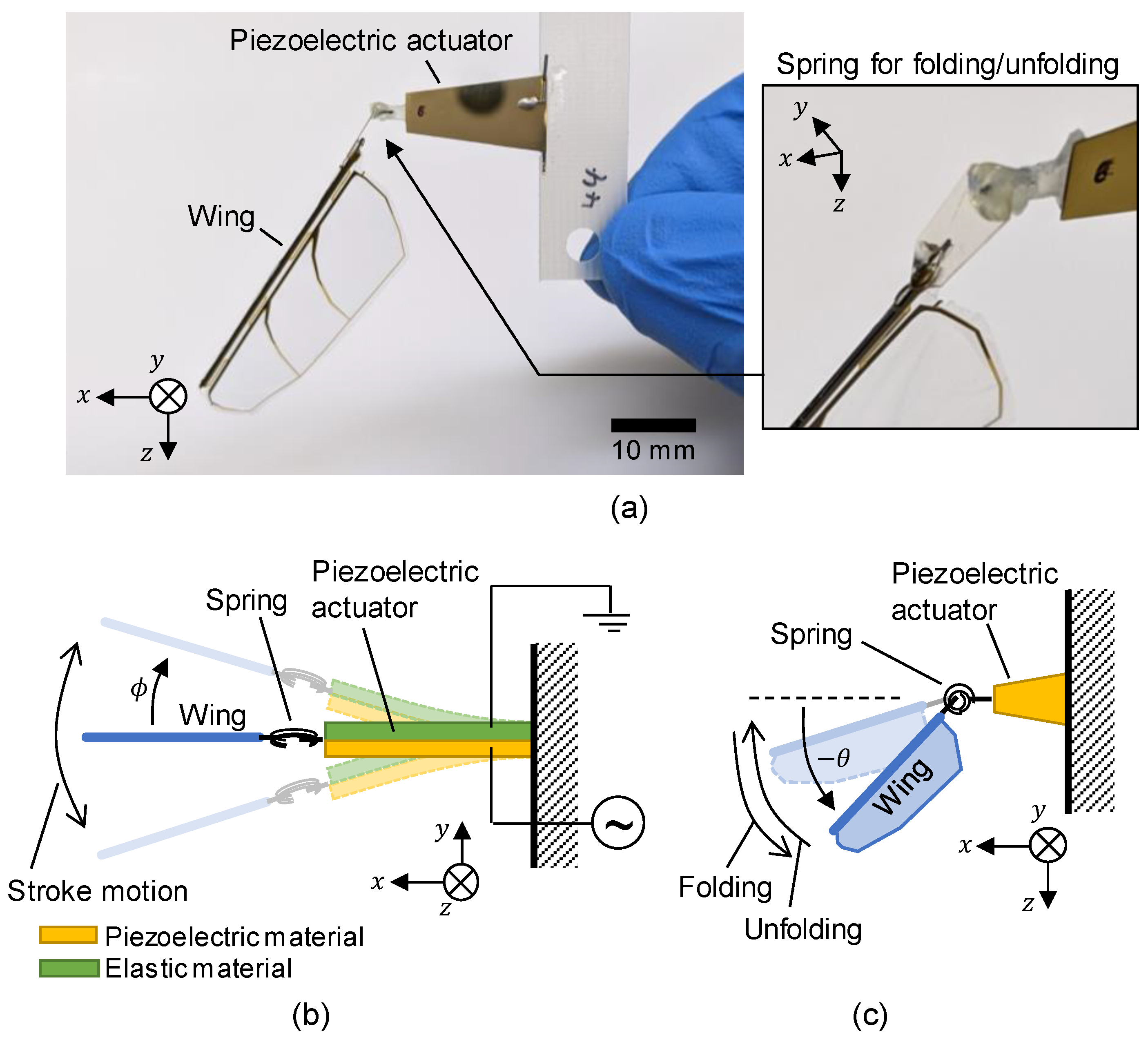
Figure 1a shows photographs of the flapping-wing actuator investigated in this study. This structure is based on our previously reported flapping-wing robot [10]. It is composed of a trapezoidal unimorph piezoelectric actuator and a biomimetic wing. The piezoelectric actuator consists of a 100-µm-thick piezoelectric Pb(In1/2Nb1/2)O3-Pb(Mg1/3Nb2/3)O3-PbTiO3 (PIN-PMN-PT) plate and a 130-µm-thick Ti plate. The PIN-PMN-PT plate was manufactured by TRS Technologies, Inc. (State College, PA, USA). The wing consists of a carbon fiber reinforcing plastic (CFRP) leading-edge rod, Ti/polyimide composite veins, and a polyester membrane; these are laminated by hot pressing. The mass of the wing is 17.8 mg. The wing is fixed at the tip of the piezoelectric actuator and its wingspan extends obliquely downward. A spring, which is a key component for the folding/unfolding function, was placed between the piezoelectric actuator and wing. Figure 1a (right) shows the enlarged image of the leaf spring made up of a 100-µm-thick polyether ether ketone sheet. The mass of the while device is 140 mg. Figure 1b illustrates the principle of the flapping actuation. When a voltage is applied to the piezoelectric material, a stress is induced in it by the piezoelectric effect. This stress bends the actuator, causing the wing to swing around the z-axis. By applying a cyclic voltage wave, the frequency of which matches the system resonance, a large stroke motion can be excited. As reported in [11,12,13], the flapping wing generates a lift force. Here, the stroke angle (the angle between the wingspan and x-axis around the z-axis) is defined as . Figure 1c illustrates the folding/unfolding behavior. The leaf spring enables the wing to rotate around the y-axis. In this paper, we defined the initial wing attitude (oblique to x-axis) as the folded state. In contrast, a state in which the wing is directed nearly along the x-axis is defined as the unfolded state. The angle between the wingspan and x–y plane is defined as . The folding/unfolding motion defined in this study is not accurately biomimetic; the wing itself does not deform but the wing root is folded. We consider this structure to have an advantage in terms of the clear understanding of the folding/unfolding behavior owing to its simple kinematics compared with a fully biomimetic morphing wing system. This structure does not use the active mechanism to fold/unfold the wing as stated in the above-mentioned section; instead, the wing will be passively folded/unfolded by forces, such as centrifugal and lift forces, due to the stroke motion.
2.2. Modelling
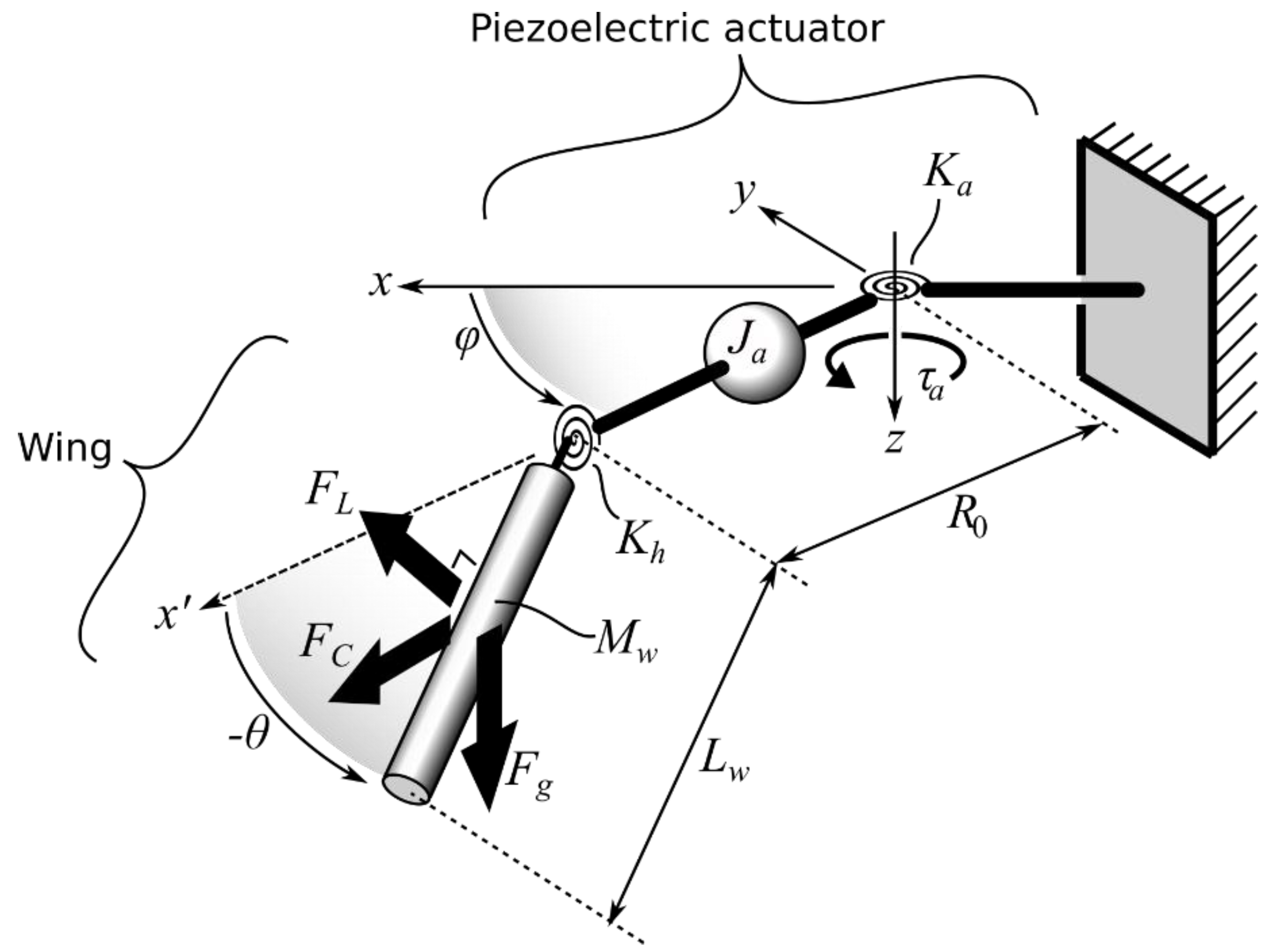
In this section, we describe a simplified theoretical model of the system to clarify the condition of the folding/unfolding motion. In Section 4, we will simulate the folding/unfolding characteristics based on this model and compare it with the measured result. Figure 2 shows the simplified system used to derive the model. The piezoelectric actuator is modeled as a 1 degree-of-freedom (DoF) spring, , with the inertia of the actuator with respect to denoted as . The piezoelectric actuation torque is represented by , the mass of the wing is , and the length of the wing is . We consider that three forces act on the wing: centrifugal, lift, and gravitational forces. The lift force was modeled as a perpendicular force to the wingspan, ; the centrifugal forces due to the stroke motion and gravitational force are represented by and , respectively. Moreover, the spring for the folding/unfolding motion has a spring constant of .
The main approximations used to derive the simplified model are summarized as follows.
- -
- Piezoelectric torque is approximated to be proportional to the applied voltage; any nonlinear effects of piezoelectricity were neglected.
- -
- Because the CFRP leading edge rod contributes to most of the wing mass, the wing is regarded as a uniform rigid bar in consideration of its inertial characteristics.
- -
- Although the wing has a biomimetic, rounded shape, we approximate it as a simple rectangle to derive the aerodynamic lift force.
- -
- Because the stroke frequency is much faster than the response speed of the folding/unfolding motion, the folding/unfolding system is subjected to the time-averaged forces of and .
- -
- We only consider an equilibrium state and not a transient response for the folding/unfolding motion
- -
- The stroke motion system is simply modeled as a second-order system. Thus, the drag force of the wing is approximated as a linear damping force. In addition, we neglect any geometric nonlinearities.
The equilibrium folding angle is given by the torque balance equation:
where , and are torques due to the centrifugal, lift, and gravitational forces, respectively, which are formulated in the following text. The bar symbol indicates time averaging. These torques also depend on and other parameters related to the applied driving signal.
2.2.1. Centrifugal Force
Here, we define as a coordinate along the wingspan, which originates from the wing root. Because the distance from the center of the stroke motion (z-axis) to a position on the wing () is expressed as , the centrifugal force acts on a small element of the wing, , which is defined as
where is the line density along the wingspan. Thus, the torque on the small element is formulated based on Equation (2) as
By integrating Equation (3) along the wingspan, can be obtained as
Assuming the stroke motion as sinusoidal, a time-averaged centrifugal torque, , is expressed as a function of , and :
where and are the angular frequency and amplitude of the stroke motion, respectively.
Stroke amplitude is determined by the resonant system about and the applied driving signal. Because it is regarded as a second-order system, is obtained as [14]
where is the ratio of ω to the resonant angular frequency of the system, (); is the damping ratio; and is the amplitude of applied actuation torque. and are defined using the inertia, damping factor, and spring constant of the system (, and , respectively) as
Because the torque generated by a piezoelectric actuator is linear to the applied voltage, it can be expressed as
where and are the proportional gain constant and applied voltage amplitude. By substituting Equations (6)–(8) into Equation (4), can be expressed as a function of , and . Based on the rigid-bar approximation, the inertia of the wing around the z-axis can be given by . Thus, is expressed as a sum of the wing inertia, and is expressed as
Assuming the deformation of the piezoelectric actuator as parabolic, is given by
where is the area density of the actuator [13], and , and are the tip width, root width, and length of the actuator, respectively. Moreover, is given by
where is the bending stiffness of the actuator per unit width [13].
We approximate the aerodynamic drag pressure as a concentrated damping force, , acting on the center of the wing; , where and are a constant and the velocity at the center of the wing. Because , a torque due to the aerodynamic damping force is expressed as . Thus, damping factor is obtained by as
In this study, we derive as
where , and are the air density, drag coefficient, wing area, and representative velocity of the wing stroke motion, respectively. In summary, by substituting Equations (9)–(13) into Equation (6), can be formulated with the actuator specifications and .
2.2.2. Lift Force
Similar to the derivation of the centrifugal force, we consider that the lift force acts on a small element of the wing, , which is expressed as
where and are the lift coefficient and wing chord width, respectively [15]. Torque is given calculated as ; thus, total lift torque is obtained by integration of based on Equation (14) as
The time-averaged lift torque is calculated based on Equation (15) as
Similar to , by substituting Equations (6) and (8) into Equation (16), can be rewritten as a function of , and .
2.2.3. Gravitational Force
The gravitational force is denoted by . Thus, the torque due to this force is expressed as
Considering that the folding/unfolding spring length is enough smaller than the wingspan length, we approximate that the spring receives only pure torques and its spring constant is expressed as
where , and are the Young’s modulus, the second moment of area, and spring length, respectively. Because we used a simple leaf spring, , where and are the width and thickness of the spring, respectively. By substituting Equations (5), (16) and (17) into Equation (1), an equation for , and can be obtained as follows:
Thus, after determining and , which represent the applied actuation voltage signal, in equilibrium can be derived by numerically solving Equation (19).
3. Experimental Method
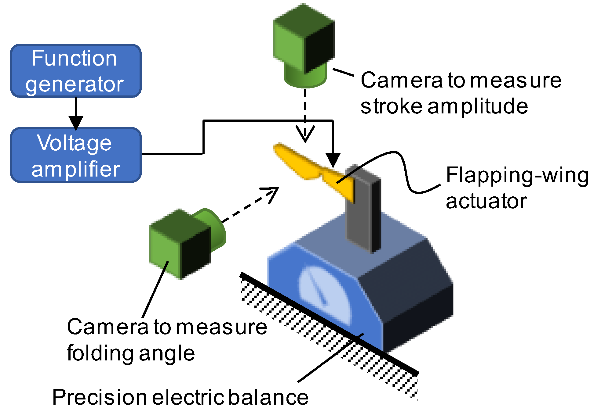
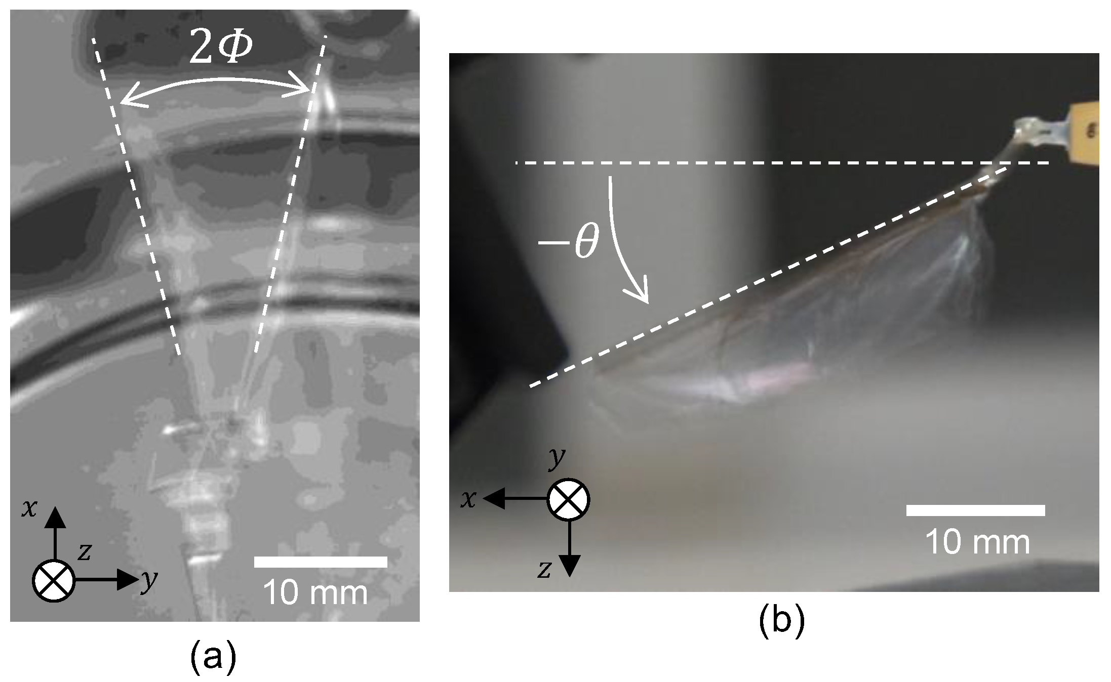
We observed the wing behavior with respect to different actuation conditions to clarify the folding/unfolding characteristics. Figure 3 depicts the measurement setup used in the experiment. We measured the average lift force and wing motion ( and ), and used a precision electric balance (HR-100A, A&D Company Limited, Tokyo, Japan) to measure the lift force. and were evaluated from the images captured by cameras (STC-CMB200PCL, OMRON SENTECH Co., Ltd, Kanagawa, Japan. and FDR-AX40, Sony, Tokyo, Japan, respectively). The piezoelectric actuator is driven by a combination of a function generator (4054B, BK Precision, Yorba Linda, CA, USA) and a voltage amplifier (HJPZ-0.3P×3, MATSUSADA PRECISION Inc., Kusatsu, Japan). In this study, we employed a sinusoidal waveform from 0 to , , as the driving signal. Figure 4 shows the images captured by the two cameras in the measurement setup (Figure 3). As stated in Section 2, we measured the angles of the leading edge from these images and estimated and .
4. Results and Discussion
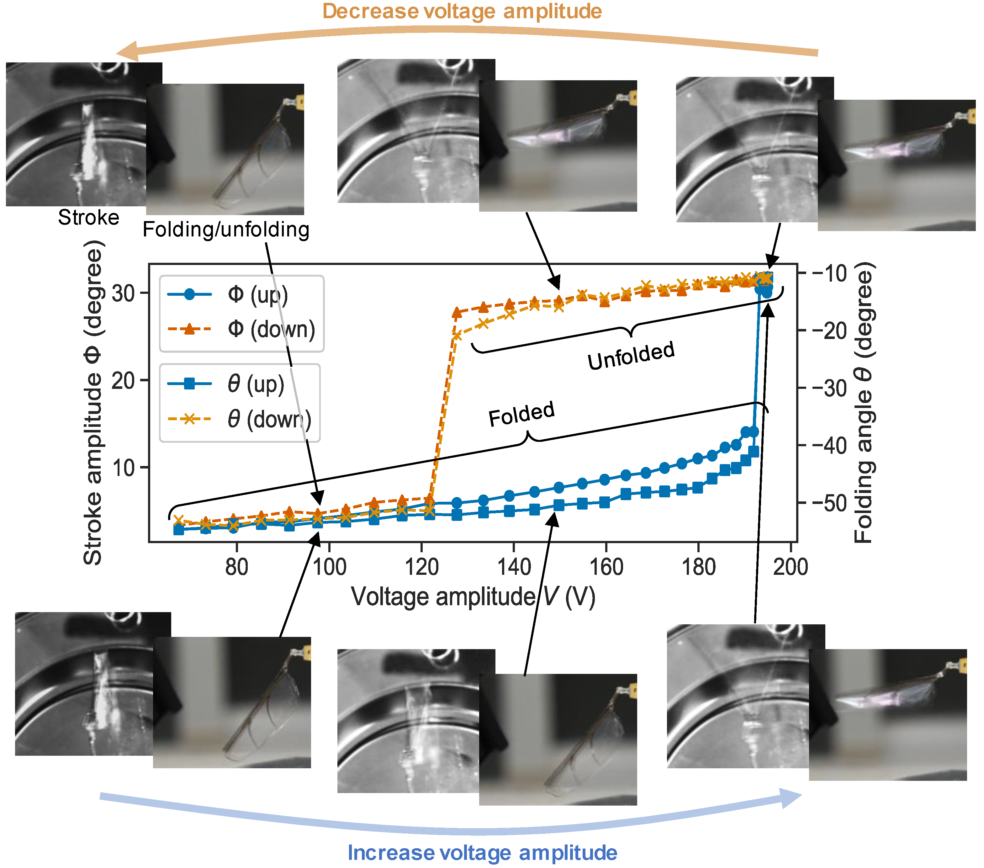
In this section, we first present the observed folding/unfolding behavior, and then compare the measurement and theoretical solutions. Figure 5 shows the measured values of and with sweeping of the applied voltage amplitude, . Here, is fixed at 95 Hz. The figure also presents images captured via the cameras for easy understanding. First, we consider the case of increasing . For V, was small and the wing remained in the folded state ( was largely negative). When exceeded 193 V, and showed a sudden increase, and the wing was unfolded. In contrast, for a decreasing , for V, although and were almost equal to those in the case of increasing ; they do not show a sudden increase for V. In addition, the wing remained in the unfolded state even when V exceeds the jump-up voltage and finally drops to V. This hysteresis behavior indicates that the fabricated actuator is a bistable system.
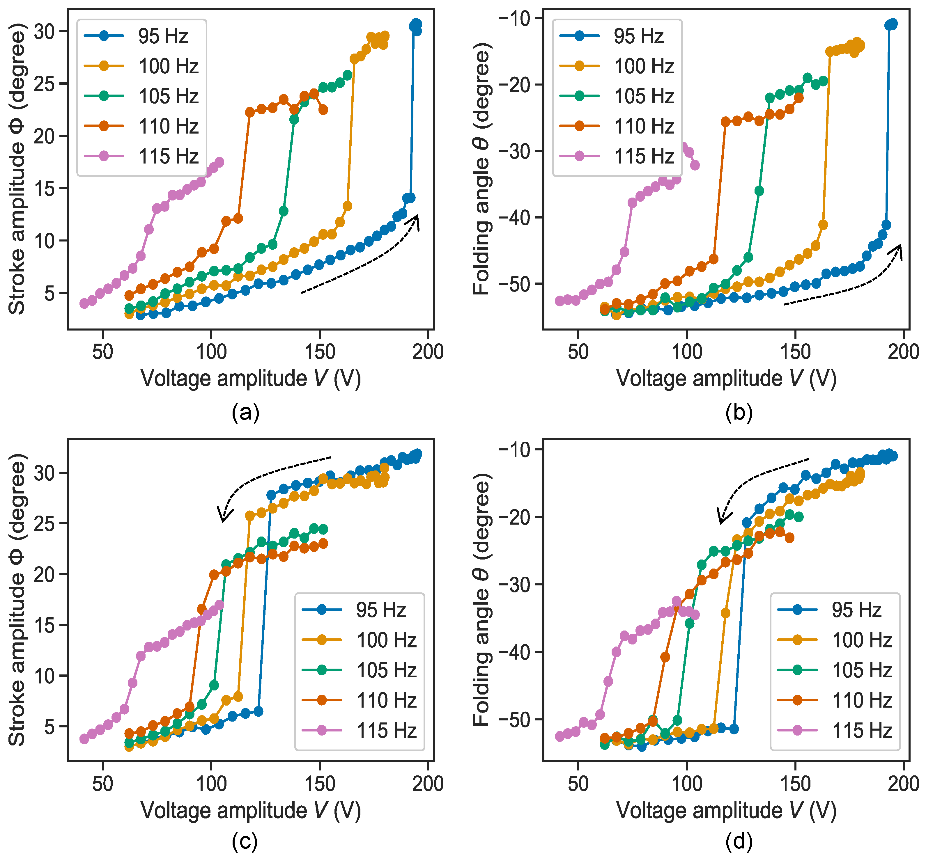
We measured the and curves at different frequencies, as shown in Figure 6. Figure 6a,b show and with increasing , respectively, and Figure 6c,d show and with decreasing . The jump-up/down voltages of and were identical with the all frequencies. We determined that a lower frequency resulted in higher jump-up and jump-down voltages. In addition, and in the unfolded state increase with decreasing frequency. This trend can be explained in a qualitative manner as follows. To unfold the wing, a large torque exerted by the centrifugal or lift force is needed, thus suggesting the requirement of a large because these forces are proportional to . depends on and the closeness of to the resonant frequency; this helps determine the magnitude of the resonant amplification. When considered together, either a sufficiently high or close enough to the resonant frequency is required to unfold the wing. The system in the folded state has a relatively higher resonant frequency than that in the unfolded state owing to its smaller inertia around the z-axis. Thus, the jump-up voltage should decrease with a higher ; a higher value matches the resonant frequency of the folded state more than that of the unfolded state and will result in a large and lower torque (or ). After unfolding (jump-up), the inertia increases, while the resonant frequency of the system decreases. This results in a mismatch between and the resonance. Thus, in the unfolded state with a higher is considered to be smaller than that for a lower . Next, in the unfolded state with a higher also decreases because smaller value of results in smaller values of centrifugal and lift forces. Conversely, a smaller results in a larger jump-up voltage and larger and . This is because a smaller matches the resonant frequency of the unfolded state more than that of the folded state.
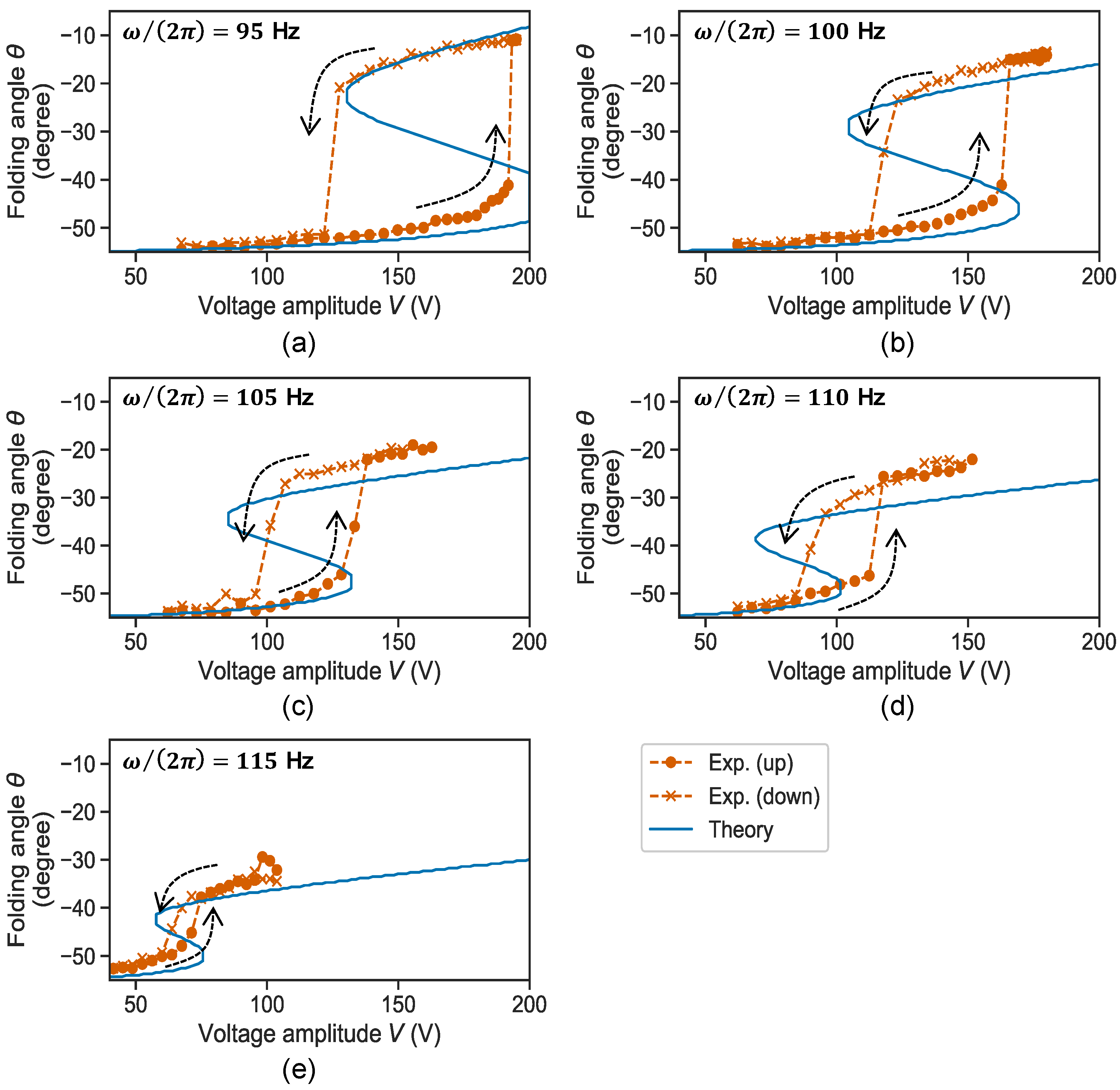
Next, we compare the experimental results with the simplified theoretical model. In Figure 7, the solution of Equation (19) is represented by blue lines (the parameters used in solving the equation are summarized in the Appendix A), and the measured values are plotted as red points and crosses. The theoretical solutions show S-shape curves; the overhanging region represents a set of unstable solutions, and the other region represents stable solutions. The top and bottom lines of the S-shape indicate two stable solutions at , i.e., bistability. Although the model is relatively simplified, the prediction curves agree well with the experiment; the bistability was successfully reproduced, and the values of were also similar to the measurement values. Thus, we concluded that the model presents the basic principle of the folding/unfolding behavior of the system.
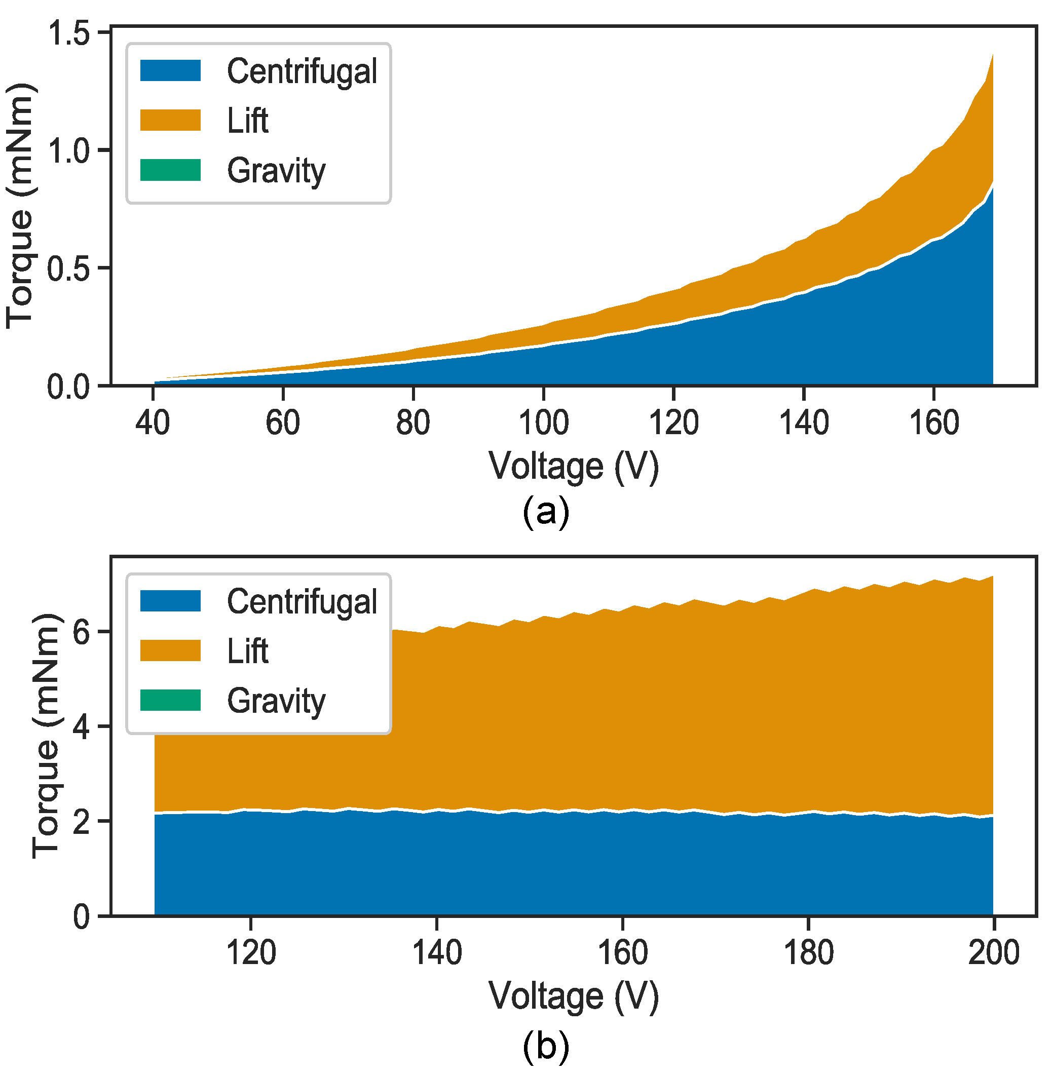
We decomposed the torque based on the model to estimate which force drives the unfolding motion. Figure 8a shows the torque factors until jump-up voltage is achieved with increasing . This graph indicates that the unfolding is mainly driven by the centrifugal force. Figure 8b shows the torque in the unfolded state with decreasing . Compared with that in the folded state, the lift force is dominant in the unfolded state. This implies that the unfolded state is mainly sustained by the lift force. The contribution of the gravitational force is expected to always be very small.
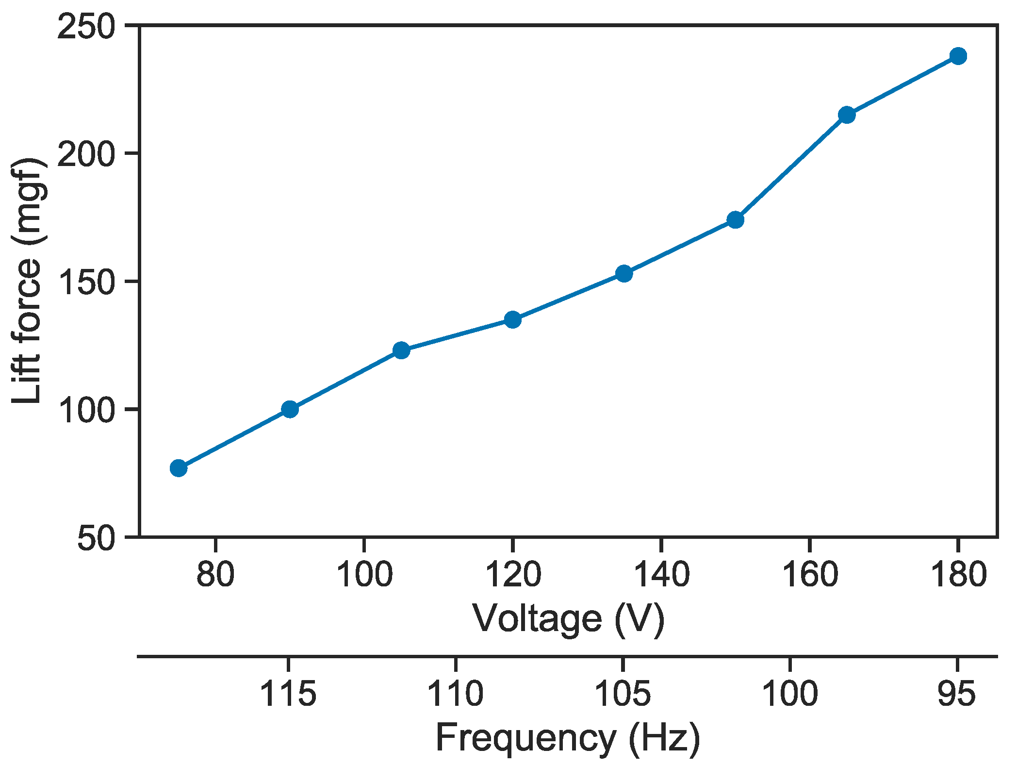
Based on the measured data, a stable unfolded state can be realized over a certain voltage with a constant . This seems to be unfavorable in actual MAV applications, which require wide range of modulations of the lift force. Because the lift force is proportional to the square of , it is desired to stably control in a wide range. Here, we propose a method to widen the stable region. The experimental results showed that a lower can be stably achieved using a higher , and vice versa. This suggests a simple strategy of simultaneously modulating and as
Note that this was determined empirically from the experiments. Based on this modulation strategy, we measured the lift force, as shown in Figure 9. The actuator shows a stable unfolded state in , which is much wider than that obtained for a constant . In addition, a wide range of lift-force modulation was successfully demonstrated, where the lift force was varied from 77 to 238 mgf. This result indicates a promising potential of the actuation system for MAV applications.
5. Conclusions
The proposed resonant system was observed to show hysteresis and bistability, caused by the resonant frequency shift due to the folding/unfolding motion. This behavior was successfully explained using a simplified analytical model. This work provides a basic understanding of the resonant-driven passive folding/unfolding mechanism and could contribute to the future development of flapping-wing MAVs that are smaller than a hummingbird. However, this study has certain limitations, summarized as follows:
- -
- Because we only considered quasi-static characteristics of the folding/unfolding motion, the dynamic behaviors of the system, such as the response against impulsive external forces, are still unclear.
- -
- The contributions of the neglected nonlinearities are not quantified. They possibly become indispensable in other cases.
- -
- In our experiments, the actuator was rigidly fixed. Thus, any unexpected phenomenon occurring during flight due to the inertial force has not been considered.
We also provided a control method to widen the stable region by simultaneously modulating and . We only carried out experimental demonstrations, but not any theoretical consideration, generalization, or optimization. Thus, further examination is needed in the future.
As a future work, we will develop an MAV equipped with an actuator with folding/unfolding capability and try to demonstrate flight takeoff.
Author Contributions
Conceptualization and evaluation: T.O. and N.O.; formal analysis, actuator design, and writing: T.O.; supervising: K.H. All authors have read and agreed to the published version of the manuscript.
Funding
This research received no external funding.
Conflicts of Interest
The authors declare no conflict of interest.
Appendix A
Table A1 lists the parameters used in the calculation. The aerodynamic coefficients, . and , are calculated as [16]
where is the angle-of-attack. We substitute ° to derive the values. and were derived by equations reported in [13]. To calculate by using Equation (18), we employed GPa, m4, and mm.

Table A1.
Parameters used in the theoretical calculation.
| Parameters | Value |
|---|---|
| (kg/m3) | 1.29 |
| (mm) | 32.4 |
| (mm) | 8.34 |
| (mg) | 9.35 |
| 1.35 | |
| 1.70 | |
| (mm/s) | 8.2 |
| (mm) | 4.0 |
| . (mm) | 8.0 |
| (Nm) | |
| (mm) | 15.6 |
| (mm) | 4.0 |
| (kg/m2) | 1.09 |
| (Nm/V) | |
| (Nm) |
References
- Muhammad, A.; Park, H.C.; Hwang, D.Y.; Byun, D.; Goo, N.S. Mimicking unfolding motion of a beetle hind wing. Chin. Sci. Bull. 2009, 54, 2416–2424. [Google Scholar] [CrossRef]
- Nguyen, Q.; Park, H.; Byun, D.; Goo, N. Recent progress in developing a beetle-mimicking flapping-wing system. In Proceedings of the World Automation Congress (WAC), Kobe, Japan, 19–23 September 2010; pp. 1–6. [Google Scholar]
- Ma, N.; Zhou, X.; He, G. Design and analysis of a bat-like active morphing wing mechanism. In Proceedings of the 40th Mechanisms and Robotics Conference, Charlotte, NC, USA, 22–24 August 2016. [Google Scholar]
- Siddall, R.; Ancel, A.O.; Kovač, M. Wind and water tunnel testing of a morphing aquatic micro air vehicle. Interface Focus 2017, 7, 20160085. [Google Scholar] [PubMed]
- Luca, M.D.; Mintchev, S.; Heitz, G. Bioinspired morphing wings for extended flight envelope and roll control of small drones. Interface Focus 2017, 7, 20160092. [Google Scholar] [CrossRef] [PubMed]
- Stowers, K.S.; Lentink, D. Folding in and out: Passive morphing in flapping wings. Bioinspir. Biomim. 2015, 10, 025001. [Google Scholar] [CrossRef] [PubMed] [Green Version]
- Wood, R.J. The First Takeoff of a Biologically Inspired At-Scale Robotics Insect. IEEE Trans. Robot. 2008, 24, 341–347. [Google Scholar] [CrossRef]
- Azhar, M.; Campolo, D.; Lau, G.; Hines, L.; Sitti, M. Flapping wings via direct driving by DC motors. In Proceedings of the IEEE International Conference on Robotics and Automation, Karlsruhe, Germany, 6–10 May 2013; pp. 1397–1402. [Google Scholar]
- Zou, Y.; Zhang, W.; Zhang, Z. Liftoff of an electromagnetically driven insect inspired flapping wing robot. IEEE Trans. Robot. 2016, 32, 1285–1289. [Google Scholar] [CrossRef]
- Ozaki, T.; Hamaguchi, K. Bioinspired flapping-wing robot with direct-driven piezoelectric actuation and its takeoff demonstration. IEEE Robot. Autom. Lett. 2018, 3, 4217–4224. [Google Scholar]
- Dickinson, M.H.; Lehmann, F.-O.; Sane, S.P. Wing rotation and the aerodynamic basis of insect flight. Science 1999, 284, 1954–1960. [Google Scholar] [PubMed]
- Sane, S.P.; Dickinson, M.H. The aerodynamic effect of wing rotation and a revised quasi-steady model of flapping flight. J. Exp. Biol. 2002, 205, 1087–1096. [Google Scholar] [PubMed]
- Ozaki, T.; Hamaguchi, K. Electro-aero-mechanical model of piezoelectric direct-driven flapping-wing actuator. Appl. Sci. 2018, 8, 1699. [Google Scholar] [CrossRef] [Green Version]
- Cannon, R.H. Dynamics of Physical Systems; Dover Publications: New York, NY, USA, 2003. [Google Scholar]
- Rathakrishnan, E. Theoretical Aerodynamics; John Wiley & Sons, Inc.: Somerset, NJ, USA, 2013. [Google Scholar]
- Taha, H.E.; Hajj, M.R.; Beran, P.S. State-space representation of the unsteady aerodynamics of flapping flight. Aerosp. Sci. Technol. 2014, 34, 1–11. [Google Scholar] [CrossRef] [Green Version]
Figure 1.
Structure of the flapping-wing actuator with passive folding/unfolding mechanism: (a) photograph of the actuator and spring for folding/unfolding; (b) stroke motion and (c) folding/unfolding motion.
Figure 1.
Structure of the flapping-wing actuator with passive folding/unfolding mechanism: (a) photograph of the actuator and spring for folding/unfolding; (b) stroke motion and (c) folding/unfolding motion.

Figure 2.
Simplified model of the flapping-wing actuator.

Figure 3.
Measurement setup.

Figure 4.
Typical captured image showing (a) stroke amplitude and (b) folding angle.

Figure 5.
Relationship among the applied voltage, stroke amplitude, and folding angle at a frequency of 95 Hz.
Figure 5.
Relationship among the applied voltage, stroke amplitude, and folding angle at a frequency of 95 Hz.

Figure 6.
Characteristics of stroke amplitude and folding angle on frequency: (a) stroke amplitude and (b) folding angle with increasing applied voltage amplitude; (c) stroke amplitude and (d) folding angle with decreasing applied voltage amplitude.
Figure 6.
Characteristics of stroke amplitude and folding angle on frequency: (a) stroke amplitude and (b) folding angle with increasing applied voltage amplitude; (c) stroke amplitude and (d) folding angle with decreasing applied voltage amplitude.

Figure 7.
Comparison between experimental and theoretical results with frequencies of (a) 95 Hz, (b) 100 Hz, (c) 105 Hz, (d) 110 Hz, and (e) 115 Hz.
Figure 7.
Comparison between experimental and theoretical results with frequencies of (a) 95 Hz, (b) 100 Hz, (c) 105 Hz, (d) 110 Hz, and (e) 115 Hz.

Figure 8.
Contributions of different forces on the unfolding torque in the (a) folded state and (b) unfolded state at Hz.
Figure 8.
Contributions of different forces on the unfolding torque in the (a) folded state and (b) unfolded state at Hz.

Figure 9.
Lift force control based on simultaneous modulation of voltage and frequency.

© 2020 by the authors. Licensee MDPI, Basel, Switzerland. This article is an open access article distributed under the terms and conditions of the Creative Commons Attribution (CC BY) license (http://creativecommons.org/licenses/by/4.0/).
Share and Cite
MDPI and ACS Style
Ozaki, T.; Ohta, N.; Hamaguchi, K. Resonance-Driven Passive Folding/Unfolding Flapping Wing Actuator. Appl. Sci. 2020, 10, 3771. https://doi.org/10.3390/app10113771
AMA Style
Ozaki T, Ohta N, Hamaguchi K. Resonance-Driven Passive Folding/Unfolding Flapping Wing Actuator. Applied Sciences. 2020; 10(11):3771. https://doi.org/10.3390/app10113771
Chicago/Turabian StyleOzaki, Takashi, Norikazu Ohta, and Kanae Hamaguchi. 2020. "Resonance-Driven Passive Folding/Unfolding Flapping Wing Actuator" Applied Sciences 10, no. 11: 3771. https://doi.org/10.3390/app10113771
Note that from the first issue of 2016, this journal uses article numbers instead of page numbers. See further details here.