Resilient Self-Triggered Control for Voltage Restoration and Reactive Power Sharing in Islanded Microgrids under Denial-of-Service Attacks

School of Electrical and Electronic Engineering, North China Electric Power University, Beijing 102206, China
*
Author to whom correspondence should be addressed.
Appl. Sci. 2020, 10(11), 3780; https://doi.org/10.3390/app10113780
Submission received: 15 April 2020
/
Revised: 20 May 2020
/
Accepted: 27 May 2020
/
Published: 29 May 2020
(This article belongs to the Special Issue Advances and Trends in Smart Grids and Microgrids: Operation, Control, Protection, and Security)
Abstract
:This paper addresses the problem of voltage restoration and reactive power sharing of inverter-based distributed generations (DGs) in an islanded microgrid subject to denial-of-service (DoS) attacks. Note that DoS attacks may block information exchange among DGs by jamming the communication network in the secondary control level of a microgrid. A two-layer distributed secondary control framework is presented, in which a state observer employing the multiagent system (MAS)-based ternary self-triggered control is implemented for discovering the average information of voltage and reactive power in a fully distributed manner while highly reducing communication burden than that the periodic communication way. The compensation for the reference signal to the primary control is acquired according to the average estimates to achieve voltage restoration while properly sharing reactive power among DGs. An improved ternary self-triggered control strategy integrating an acknowledgment (ACK)-based monitoring mechanism is established, where DoS attacks are modeled by repeated cycles of jamming and sleeping. A new triggering condition is developed to guarantee the successful information exchange between DGs when the sleep period of DoS attacks is detected. Using the Lyapunov approach, it is proved that the proposed algorithm allows agents to reach consensus regardless of the frequency of the DoS attacks, which maintains the accurate estimation of average information and the implementation of the secondary control objectives. The performance of the proposed control scheme is evaluated under simulation and experimental conditions. The results show that the proposed secondary control scheme can highly reduce the inter-agent communication as well as improve the robustness of the system to resist DoS attacks.
1. Introduction
Distributed generation (DG) technology is characterized by low environmental pollution, high energy utilization rate, and flexible installation sites, which enhances the power supply reliability of the distribution network. Particularly in the case of natural disasters, it ensures the basic energy supply of critical infrastructure and residents in the remote areas [1]. To coordinate the contradiction between DGs’ intermittent characteristics and bulk power system, and fully exploit the benefit of DGs, the concept of microgrid was proposed at the beginning of this century [2]. A microgrid consists of distributed renewable resources, energy storage system, and various types of loads. It is capable of operating in either a grid-connected mode or an islanded mode, and handling the transitions between these two operation modes. In an islanded microgrid, the conventional control strategy produces the output voltage deviations from their nominal values as well as the failure of reactive power sharing among DGs connected via different line impedances, thereby affecting the power supply quality and system dynamic performance of microgrids [3,4].
The hierarchical control structure is an effective way for the coordination of multiple DGs in microgrids [5]. In order to maintain the stability of frequency and voltage, the primary control of a microgrid employs a droop control method that is completely decentralized and only depends on local information without requiring any communication between the DGs. However, the droop control causes deviations of the voltage and frequency from their nominal values. Hence, the secondary control level is necessary to compensate for the deviations caused by the primary droop technique. The tertiary control level is aimed at the economical dispatch and optimized management of power flow in the microgrid.
This paper aims to address the voltage restoration and reactive power sharing problem in the secondary control level of an islanded microgrid with multiple inverter-based DGs. In general, the secondary control strategies for microgrids are categorized into three types: centralized [6], distributed [7], and decentralized [8]. Microgrids are characterized by small electrical distances between DGs, lack of static compensation devices, and line impedance mismatch [9], which makes the primary droop control fail to achieve accurate reactive power sharing among the DGs. Such a failure in turn possibly causes DGs overloads and damages the stability of the whole system. The authors of [10,11] proposed centralized control architectures for voltage restoration and reactive power sharing, in which each DG demands to communicate with a central controller. The centralized manner requires a complicated two-way communication network and any single point failure may cause serious instability of the entire system. For enhancing the scalability and flexibility, a multiagent system (MAS)-based distributed secondary control scheme using only local neighbors’ information is more desirable in microgrids. Cooperative secondary controllers by using a multiagent pinning consensus [12], finite-time consensus [13], and distributed averaging proportional integral (DAPI) [14] have been deliberately designed for voltage or/and powering sharing control. Since the objective of most studies is to synchronize the voltages of DGs to nominal values, accurate reactive powering sharing among DGs is impossible. And most recent work does not consider the influence on the consensus algorithm of the potential malicious attacks induced by the communication network.
In the MAS-based distributed cooperative control scheme, each DG is considered as an agent that exchanges information with its neighbors through communication networks. Conventional continuous-signal-based communication requires real-time data transmissions between DGs. The continuous-time-based control method can hardly be realized due to the constraints of channel bandwidth and computing resources in practical engineering. Moreover, the sampled-data communication mechanism requires higher communication rates to satisfy the worst possible extreme situations, which would increase the burden of networks and cause time delay or packet loss. According to [15], the event-triggered communication mechanism was proposed for microgrid secondary control to realize need-based data exchanges while meeting the performance requirements. A similar event-triggered control strategy was also applied in [16]. However, it is noteworthy that event-triggered communication requires continuous monitoring of the state variables of agents, which would place a heavy computation burden on each DG local controller. Moreover, the objectives of the abovementioned event-triggered method are only to synchronize the output voltages of DGs to their nominal values or realize reactive power sharing without considering voltage restoration. To the author’s knowledge, the secondary control for average voltage restoration while maintaining reactive powering sharing using an appropriate event-triggered communication mechanism has not been discussed.
While the communication network facilitates distributed control strategies, it leads to the vulnerability of microgrids to malicious cyber attacks. In general, cyber attacks can be categorized into: denial-of-service (DoS) attacks and deception attacks. Deception attack, such as false data attack (FDIA) and replay attack, is to compromise the integrity of measurements or transmitted data packets, while DoS attack is to block legitimate data transmissions or interfere with receptions. In the research field of the DoS attacks’ detection mechanism, a collaborative real-time intrusion detection approach based on blockchain combined with SVM was developed in [17]. In [18], a signal temporal logic (STL)-based attack detection strategy was presented that can detect both FDIA and DoS attacks for microgrids. In the aspect of the DoS attack-resilient secondary control scheme, a software-defined microgrid control architecture was designed for resilience against DoS attacks in [19]. A finite-time control strategy was proposed for a battery energy storage system under DoS attacks in [20], but a communication recovery mechanism must be added to ensure the robustness of the method. In [21], an event-triggered control strategy was proposed for voltage restoration of a microgrid subject to DoS attacks, but this method requires the system to meet exponential stability conditions, which limits its application range. In [22], the intermittent DoS attacks were modeled as time delay and the impact of attacks on microgrid stability was analyzed, but no mitigation measures were proposed. In [23], a resilient control scheme with the power talk mechanism was established which can detect DoS attacks through adjusting droop coefficients, but this method is sensitive to load changes. Due to the fact that no communication networks are required, a decentralized control scheme has the natural advantages of resisting cyber attacks. However, it is noteworthy that the secondary control with no communication networks is still an open research field and the main challenges are related to modeling, stability, and robustness [24]. Since distributed structures have been widely studied and applied in engineering, it is of significance to propose a distributed resilient secondary control strategy to ensure voltage restoration and reactive power sharing under DoS attacks, which motivate our research.
In this paper, we focus on the distributed secondary control for average voltage restoration and reactive power sharing of an islanded microgrid by taking into account the communication burden and the impact of DoS attacks. The communication mechanism of a distributed secondary controller is changed from the traditional periodic sampling manner to a new self-triggered manner in which continuous monitoring of neighboring DG’s state can be avoided. Considering DoS attacks prevent the information transmission between DGs, an acknowledgment (ACK)-based monitoring mechanism is developed to ensure successful communications once the sleep period of attack is detected. The main contributions of this paper are summarized as follows: (1) A two-layer secondary control scheme is proposed, where a state observer with ternary self-triggered control law is constructed and average voltages of DGs can be restored to their nominal values while maintaining accurate reactive power sharing. The communication burden between agents by our method can be highly reduced than that of the periodic way. (2) A class of time-sequence-based aperiodic DoS attacks is considered, an ACK-based monitoring mechanism is introduced to check whether the sleep period of DoS attacks has arrived. A new triggering condition is developed according to the monitoring results which ensures successful information exchanges when the sleep period is detected. (3) The stability of the proposed control strategy is proved using the Lyapunov method. The consensus of agents can be reached regardless of the frequency of DoS attacks which guarantees the achievement of secondary control objectives. Finally, simulation and experimental results are presented to verify the effectiveness and resilience of the proposed control scheme.
2. Problem Formulation
2.1. Dynamic Model of Inverter-Based Distributed Generations (DGs)
Figure 1 presents the block diagram of an islanded AC microgrid containing several DGs. Three-phase inverter-based (i = 1,…,N) is connected to the microgrid through a DC/AC inverter, an LC filter, and an output connector. Moreover, , and represent the inductance, resistance, and capacitance of the LC filter, respectively. , represent the inductance and resistance of the output connector, respectively.
The local control of is made up of the droop-based power controller, PI voltage controller and PI current controller in a cascade configuration. The power controller provides the reference for the voltage controller and the reference angular frequency for the whole control system. For , droop technique which is used in the power controller describes the desired relationship between the frequency and active power , and the relationship between the reference of output voltage magnitude and reactive power , which are given by
where and are the d-axis and q-axis components of , and output voltage can approach the reference value in steady-state. and are the frequency and voltage droop coefficients. and are fundamental components of active and reactive power which can be gained through a low-pass filter. and are the primary control reference, and is typically set equal to , where is the nominal voltage.
According to the references by the power controller, and , the differential algebraic equations of the voltage controller are written as
where and are the proportional and integral coefficients of the PI voltage control loop respectively, is the feedforward gain, and is the nominal angular frequency. By introducing feedforward quantities and , the dynamic performance of voltage controllers under disturbance can be improved. With adoption decoupling items and , the current in the d–q axis can be completely decoupled, which ensures that and are able to be controlled separately.
The current controller is responsible to make inductive currents and to track their references, and , provided by the voltage controller. The output of the current controller can be expressed as
where and denote the proportional and integral coefficients of the PI current control loop respectively. The output of current controller, and , are used as references for the PWM generator.
With the differential equations for the series LC filter and output connector discussed in [25], the large-signal state space model of can be represented as the following nonlinear system:
where the state vector is
and the control input is , the output is , and the known disturbance is . The detailed expressions of , and , and the related parameters can be seen in [25], which are omitted here. The purpose of the proposed secondary control is to regulate the average voltage of overall DGs to the nominal value by adjusting the reference input in Equation (1). Thus, the magnitude of output voltage is able to restore while achieving accurately reactive power sharing among DGs.
2.2. Distributed Secondary Control Framework for Voltage and Reactive Power
Since the output voltage of DG is a local variable, the droop-based primary control causes voltage deviations from its nominal value. The voltage droop controller is unable to achieve accurate reactive power sharing among DGs operating in parallel owing to the influence of different line impedances. To overcome the drawbacks of primary control, secondary control is necessary to compensate for voltage deviations as well as maintain reactive power sharing. Conventional control strategy for voltage restoration and reactive power sharing is a centralized architecture, which requires a two-way communication network to collect information from all DGs and then calculate the average value of voltage and reactive power [26]. Such a centralized strategy may cause communication congestion and any single point failure can destroy the stability of the system. Different from the centralized way, this paper designs a MAS-based distributed control scheme which is depicted in Figure 2.
As illustrated in Figure 2, the voltage and reactive power secondary control scheme proposed in this paper involves the estimation layer and the compensation layer. In the estimation layer, the global average information of voltage and reactive power can be obtained by a state observer employing a MAS-based ternary self-triggered control law (which will be presented in Section 3) in a fully distributed manner and then sent to the compensation layer. In the compensation layer, the reference signal is adjusted by PI controllers and then sent to the primary control level to realize voltage restoration and reactive power sharing. Unlike the conventional centralized structure, the MAS-based secondary control scheme can regulate the voltage and reactive power in the time scale of seconds, which improves the real-time response capability of the microgrid system.
In the estimation layer, the average estimates of voltage and reactive power on can be defined as . The state observer on receives its neighbors’ estimated information () via the communication network. Then, the observer updates its own estimates by processing the control input generated by the ternary self-triggered control law with its local voltage and reactive power measurements . According to the proving process and related conclusions in [27,28], when the communication topology is an undirected connected graph and the designed control law ensures the state variables (i=1,…,N) to achieve consensus, the average value of voltage and reactive power of overall DGs can be acquired by the state observer, which can be expressed as
where , and N is the total number of DGs.
In the compensation layer, measures the voltage error and compensates for the voltage deviation caused by the droop technique. The average estimate of reactive power is used as the reference to realize reactive power sharing among DGs. The voltage compensation and reactive power compensation obtained by the PI controller can be represented as follows
where and are the proportional and integral coefficients of voltage compensation for , respectively. and are the proportional and integral coefficients of reactive power compensation for , respectively.
According to the compensations, the reference signal sent to the power controller in the primary control level is updated to , which can regulate the average voltage of all DGs to the nominal value. Meanwhile, the properly reactive power sharing among DGs can also be implemented regardless of the impact of line impedance.
3. Self-Triggered Control for Islanded Microgrids under DoS Attacks
In this section, we design an improved ternary self-triggered control law to maintain the voltage restoration and reactive power sharing for microgrids under DoS cyber attacks. First, the descriptions of communication topology and DoS attacks are presented. Then, an improved ternary self-triggered control law is established with an ACK-based monitoring mechanism and theoretical analysis is conducted to prove the convergence of the proposed control algorithm.
3.1. Communication Topology
To facilitate the MAS-based distributed secondary controller, each DG in the microgrid is considered as an agent that communicates with its neighbors via the communication network. The communication topology is described as an undirected graph , where denotes the set of agent nodes corresponding to DGs, and is the set of edges corresponding to the communication links. Node j is a neighbor of node i if there is an edge defined as . is the adjacency matrix, where for all i, and if , otherwise,. is defined as the set of node i’s neighbors, and the degree of node i can be expressed as . A path is defined as a connected edge in a graph, and the graph is connected if there is a path between any two nodes.
Remark 1:
For the brevity of analysis, it is supposed that the transmissions of the estimated average information of voltage and reactive power use the common communication topology. However, different topologies may be used for information exchanges in a practical microgrid system. It is worth pointing out that the proposed self-triggered control law can be extended to accommodate the case of different communication topologies as well.
3.2. Model of DoS Attacks
In cyber physical environments, the adversaries can conduct DoS attacks by jamming communication channels, disabling sending devices, and distorting communication protocols to make parts or all components of the control system inaccessible, which would cause data loss and control failure. In general, DoS attacks can be categorized into node-based attacks and link-based attacks [20]. Node-based attacks can prevent a node from sending its state to its neighbors, while link-based attacks block information exchange between two neighboring nodes. The MAS-based secondary control scheme of microgrid requires the communication topology to maintain connectivity. DoS attacks may destroy communication connections among neighboring DGs and even ruin the stability and convergence of the MAS-based secondary control strategy. Figure 3 shows the communication network of the microgrid system under DoS attacks.
As illustrated in Figure 3, the adversaries launch DoS attacks on the communication link to block the data transmission between and . Since the adversaries with limited resources cannot continuously jam the channels for a long time, the sequence of DoS attacks repeats the cycles of jamming and sleeping. The set and the set are defined to represent the starting time instants and durations of the DoS attacks on the communication link , in which and is satisfied. The kth attack interval can be expressed as , during which the information sharing is prevented between agents i and j. In the time interval , the total duration of the attacks on the communication link can be expressed as
where the scalar and . Note that Equation (8) implies that , can be considered as the upper bound on the ratio of the total duration of DoS attacks in a long time interval. Since the jamming period cannot span the entire time, the longest duration for jamming period cannot be larger than , and can be used to model the attacker’s capability for continuous jamming.
Remark 2:
In a wireless communication network, the adversaries require energy for sending radio inference to block data transmissions. Due to resources and energy constraints, the adversaries cannot constantly jam the communication channels. Our DoS attack model can capture different scenarios, such as reactive, random, and periodic jamming attacks [29]. In a wired communication network, DoS attacks can be conducted with a flood of internet traffic to the targeted devices. The adversaries may keep the number of attacks small to make them less detectable [30]. Thus, DoS attacks cannot span the entire time and repeat the cycles of jamming and sleeping. Note that node-based DoS attacks can be considered as some or all of the links connected to the node subject to attacks. Our DoS attacks model can capture a more general scenario, in which communication links can be attacked independently.
3.3. Improved Ternary Self-Triggered Control Law Under DoS Attacks
To achieve the agent’s consensus while reducing communication requirements in the secondary control level, we improve the ternary control approach previously applied in [31,32]. The ternary variables of agent i is defined as , where is the state variable, is the local control input, and is the clock variable. The piecewise-constant control input belongs to the set , where Υ is a positive scalar. The evolution of the ternary variables of agent i can be described as
where denotes the average estimate of voltage and reactive power in . denotes the control action caused by the relative state difference between neighboring agents i and j, and the control action is fully distributed since the evolution of only depends on with . denotes the clock variable on the communication link . When reaches 0, agent i asks for the state of agent j, then updates the control input and resets the value of . Since the following update time is determined by and precomputed at the update time, the system described as Equation (9) can realize self-triggered communication [31].
The detection function for DoS attacks on the communication link is defined as , and an assumption is proposed as follows.
Assumption 1:
The detection function indicates whether the communication link is in the presence of DoS attacks and only changes its value at the triggering time instants. Specifically, at triggering time instants, if an agent attempts to communicate with its neighbors and cannot receive the information, it implies that the communication link is suffering from the DoS attacks. Then, the detection function changes value from 1 to 0, denoted as . When the attack shifts to a sleep period, an ACK-based monitoring mechanism is able to detect that the communication link returns to normal and there will be a successful information exchange between agents immediately. Then, the detection function changes value from 0 to 1, denoted as .
ACK-based monitoring mechanism: At triggering time instants, if the communication attempts are denied by the attack, an ACK-based monitoring mechanism is activated to check whether the attack shifts to a sleep period. Specifically, when the communication attempt of is blocked due to the jamming period of DoS attack, continuously sends test data packets to . When the attack shifts to a sleep period, will receive the test packets and send an acknowledgment (ACK) message back to . It is assumed that the ACK message can be transmitted successfully and the transmission time is negligible, the proposed mechanism can detect the sleep period immediately. Such implementation is practical and also applied in the cybersecurity framework for power grids [33]. The ACK-based monitoring mechanism requires no extra calculation process. Thus, the computation burden of the microcontroller is not increased and the real-time performance of the control scheme is not affected. From the above analysis, it can be seen that Assumption 1 is reasonable and feasible in practical engineering.
Remark 3:
In the secondary control framework of microgrids, communication networks can be implemented by means of wired technologies such as RS-232, ModBus, and Power-Line Communication, or wireless technologies such as Wi-Fi and ZigBee. For a successful information exchange between agents, the protocols for data transmission such as TCP/IP and IEC 61850 are also needed [34]. Assumption 1 does not require the agents to detect the occurrence of the attack in real-time, but it needs agents to know the communication failure at triggering time instant is caused by DoS attacks. This is a general assumption in the attack-resilient control scheme [20,21,32]. In wireless communication networks, statistical metrics such as signal strength consistency, packet send ratio (PSR), and packet delivery ratios (PDR) can be adopted to detect radio interference induced DoS attacks [29]. In wired communication networks, computationally low-cost machine learning methods, such as SVM and neural networks, can detect DoS attacks according to the abnormal traffic features with high accuracy [30,35]. The abovementioned detection algorithms are not difficult to apply in microgrid systems, since the local microcontroller of DGs has powerful computing capacity.
The triggering conditions are defined as and , and can be expressed as follows
where indicates that when clock variable reaches 0, there will be a communication attempt between neighboring agents i and j; is the ACK-based mechanism induced triggering condition and indicates that when the sleep period of DoS attacks is detected, agents i and agent j can successfully exchange information as well.
Define as the relative state difference between the agents i and j, and the function can be expressed as
where denotes a sign function while the parameter determines the final consensus region of the algorithm.
According to the detection function and triggering conditions, the update laws of the local control input and the clock variable can be given by
where
Equations (12)–(14) suggest that the control input and the clock variable is updated synchronously according to the relative state difference when the communication link works in normal condition and reaches 0, or when the sleep period of attacks is detected by the ACK-based monitoring mechanism. When reaches 0 and the communication attempts are denied by the jamming period of attack, the control signal is set to 0. According to the above analysis, the successful communication time instants between agents i and j are discrete, and can be represented as
where and are the kth and (k+1)th successful communication time instants, respectively. Additionally, denotes the latest detection that the DoS attacks shifts to a sleep period.
For the sake of clarity, our improved ternary self-triggered control law is summarized in Algorithm 1 and illustrated as below.
| Algorithm 1 Improved ternary self-triggered control law |
| Initialization: For agent , set clock variable , control input . |
| fori = 1 to N do |
| for j = 1 to Ni do |
| while do |
| ; |
| end while |
| if then |
| update ; |
| update ; |
| end if |
| if then |
| update ; |
| update ; |
| end if |
| if then |
| DGi constantly sends test data packets to DGj; |
| When DGi receives the ACK message from DGj, update ; |
| end if |
| end for |
| end for |
Remark 4:
It is worth noting that when is plugged out, the neighbors of are unable to receive its state information either. In order to accommodate for the topology changes and plug-and-play operation, each DG is given a unique ID and equipped with a local information table to store the connectivity information of the communication network. This table can be represented by a “0-1” matrix, where “0” indicates the corresponding communication link is absent and “1” indicates the corresponding communication link is present. When is plugged out, it will send a message to its neighboring (), and will delete the corresponding ID and update the local information table as well as its node degree . When a new DG (named ) is plugged into the microgrid, it will be given a new ID and try to find the nearest neighbors with the flooding-based graph discovery algorithm [36]. The neighbors of will update their local information table and node degrees, and then interact with to implement the secondary control scheme proposed in this paper.
3.4. Stability Analysis
The convergence of the proposed improved ternary self-triggered control law under DoS attacks is analyzed in this subsection.
Theorem 1.
For the system described as Equation (9), if topology G is undirected and connected, and DoS attack sequence that satisfies Equation (8),
converges in finite-time to a point
regardless the frequency of DoS attacks, for all .
Proof of Theorem 1.
The Lyapunov function can be defined as
where . Note that and we consider the evolution of .
Let denotes the latest triggering time instant. Firstly, we prove that there must exist a finite-time such that, for every and every l with , the control input is set equal to 0 and stops to update. Using Equations (12)–(14), the derivative of V(t) can be expressed as
where represents the summation condition. means that the agents i and j are not -close while means that the communication is allowed on link at the triggering time instant . This summation condition follows from the fact that for any , if or , we have for . In other cases, is not equal to 0. □
Using Equation (14), it can be observed that for , if , then we have
Similarly, if , then we have
The above inequalities imply that if , then preserves the sign during continuous evolution, and consequently we have . According to this fact, the following inequality can be obtained
Since Υ is a positive scalar, it can be concluded that will decrease under the summation condition. However, there must exist a finite-time such that for every and every l with , or holds true. This is because otherwise, would become negative which is in contradiction with the positive semi definiteness of Lyapunov function. From Equations (12)–(14), we can conclude that in both the cases and , the control input is set equal to 0 and stops to update.
Then, caused by the persistence of the jamming period can be excluded. According to the model of DoS attacks, the adversaries cannot permanently destroy the transmission capacity of communication links. This means that there must exist a successful triggering time instant , which can be ensured by the proposed ACK-based monitoring mechanism. Thus, caused by the persistence of the jamming period can be excluded. It can be concluded that for all and , there must exist . Since each pair of neighboring agents differs by at most and the graph G is undirected and connected, the state variable can converge to a point belonging to the set defined as follows
where N is the total number of agents. By choosing the appropriate value of , the range of the final consensus region can be small enough to improve the control accuracy of the proposed algorithm. Figure 4 shows the comparison of our algorithm and the method applied in [32].
Remark 5:
Due to the distributed property, the proposed self-triggered control scheme is reliable and cost-efficient, and suitable for scalability and flexibility of microgrids. Continuous monitoring of the state variable is not required in our method, and each linked pair of agents can exchange information independently, which improves computation efficiency while reducing communication requirements. Compared with the method used in [32], our algorithm allows the agents to achieve consensus regardless of the frequency of DoS attacks. As illustrated in Figure 4, the minimal interval between any consecutive communication attempts for agents i and j can be represented as Δ in [32]. However, this method becomes invalid in the case that the frequency of DoS attacks is larger than , because all information exchanges are blocked on communication link . By introducing the ACK-based monitoring mechanism, a new triggering condition is proposed to ensure the successful data transmissions when the attack shifts to a sleep period. Thus, even under high-frequency DoS attacks, the agent’s consensus can still be achieved by our algorithm.
4. Simulation Results and Discussion
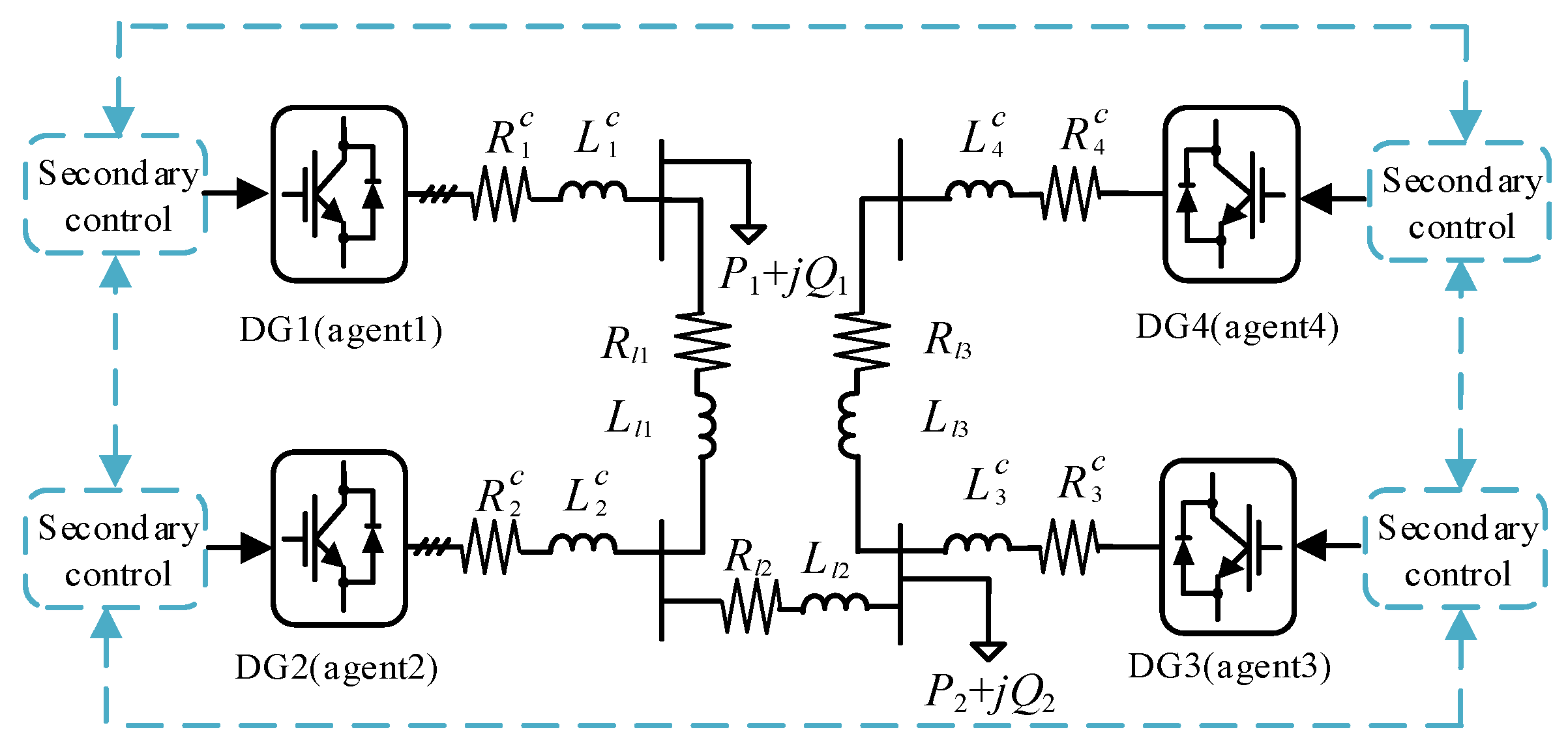
In this section, the effectiveness of the proposed secondary control scheme for voltage restoration and reactive power sharing is verified by simulating an islanded microgrid using MATLAB/Simulink toolbox. As shown in Figure 5, the studied microgrid test system consists of 4 DGs, which are connected by series RL transmission lines. In the secondary control level, the communication links between the different DGs are indicated as dotted lines. The lines’ parameters, loads, and related control parameters of the microgrid test system are given in Table 1. In the simulation, we consider DoS attacks that affect each of the communication links independently. When DoS is present, the communication network in the secondary control level is modeled as a random connected undirected graph.
4.1. Load Change with the Proposed Control Scheme
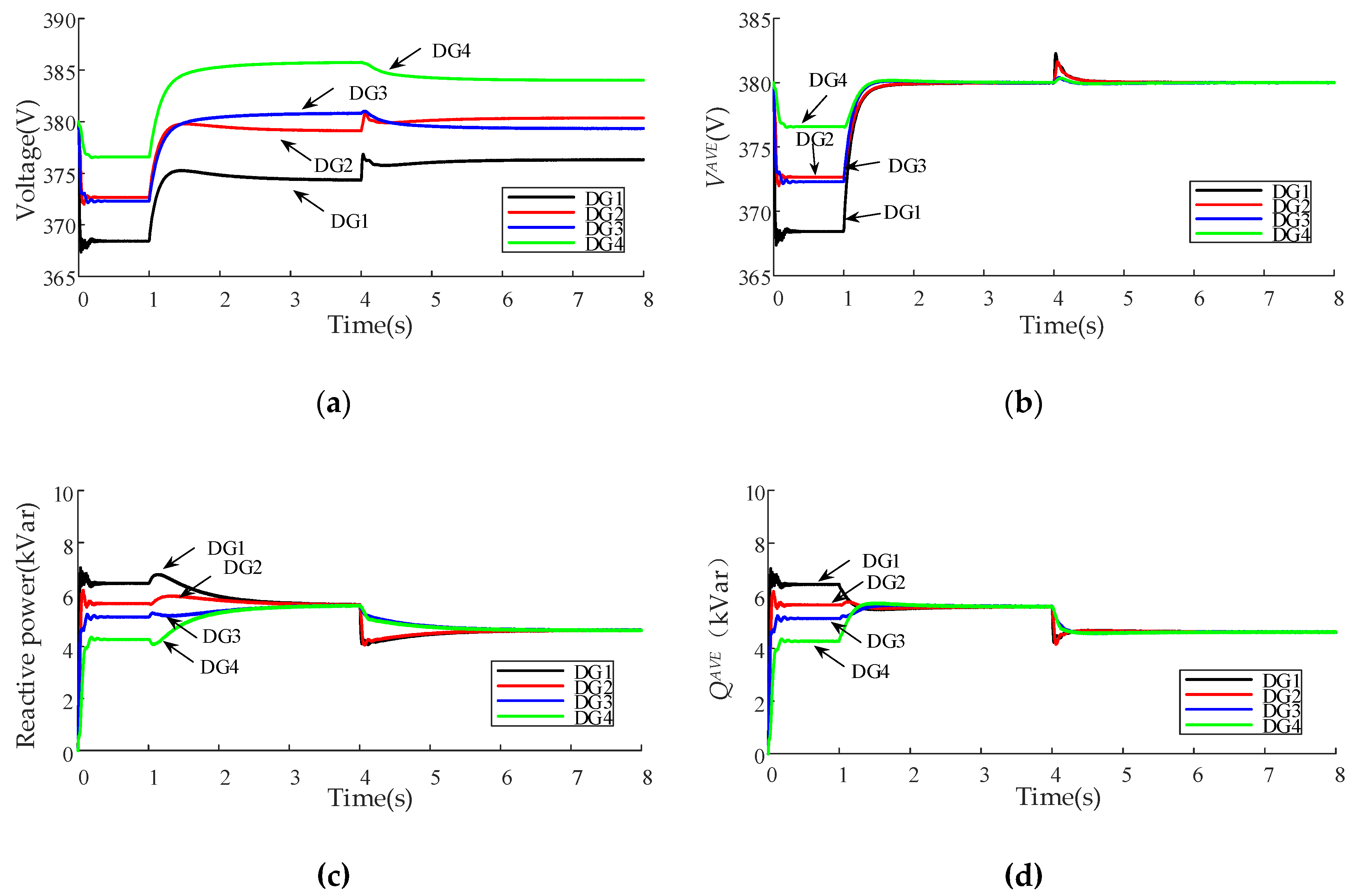
In order to verify the effectiveness of the proposed self-triggered communication enabled secondary control scheme with sudden load changes, the simulation process is designed as follows: (1) At t = 0 s, the microgrid works in islanded mode at beginning, and only the primary control is activated with the reference voltage and angular frequency (i = 1,…,4) set to 380 V and 100 π, respectively. (2) At t = 1 s, the proposed secondary control scheme is applied. (3) At t = 4 s, Load1 is reduced by the amount of 4 kVar. The simulation results are shown in Figure 6, Figure 7 and Figure 8.
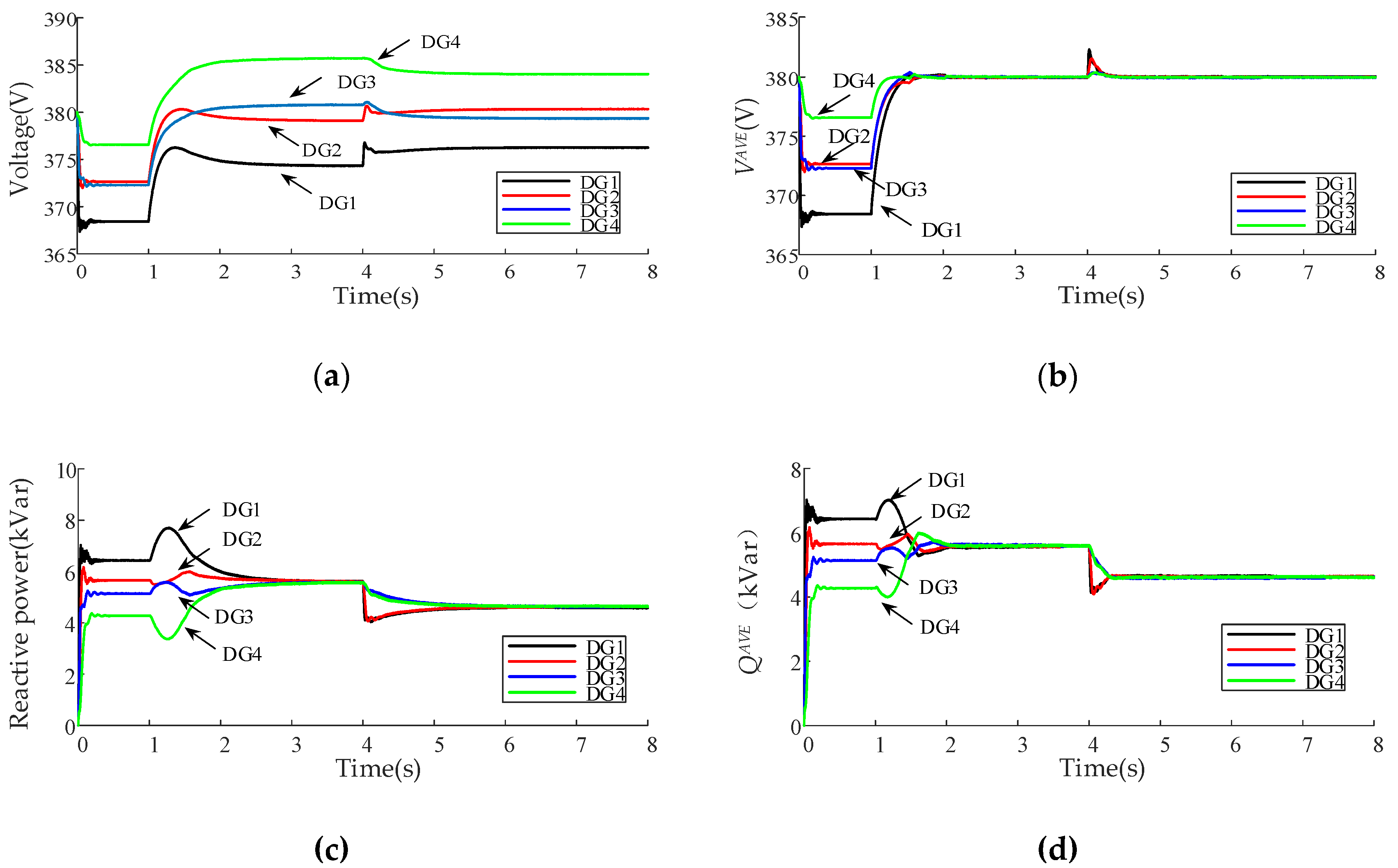
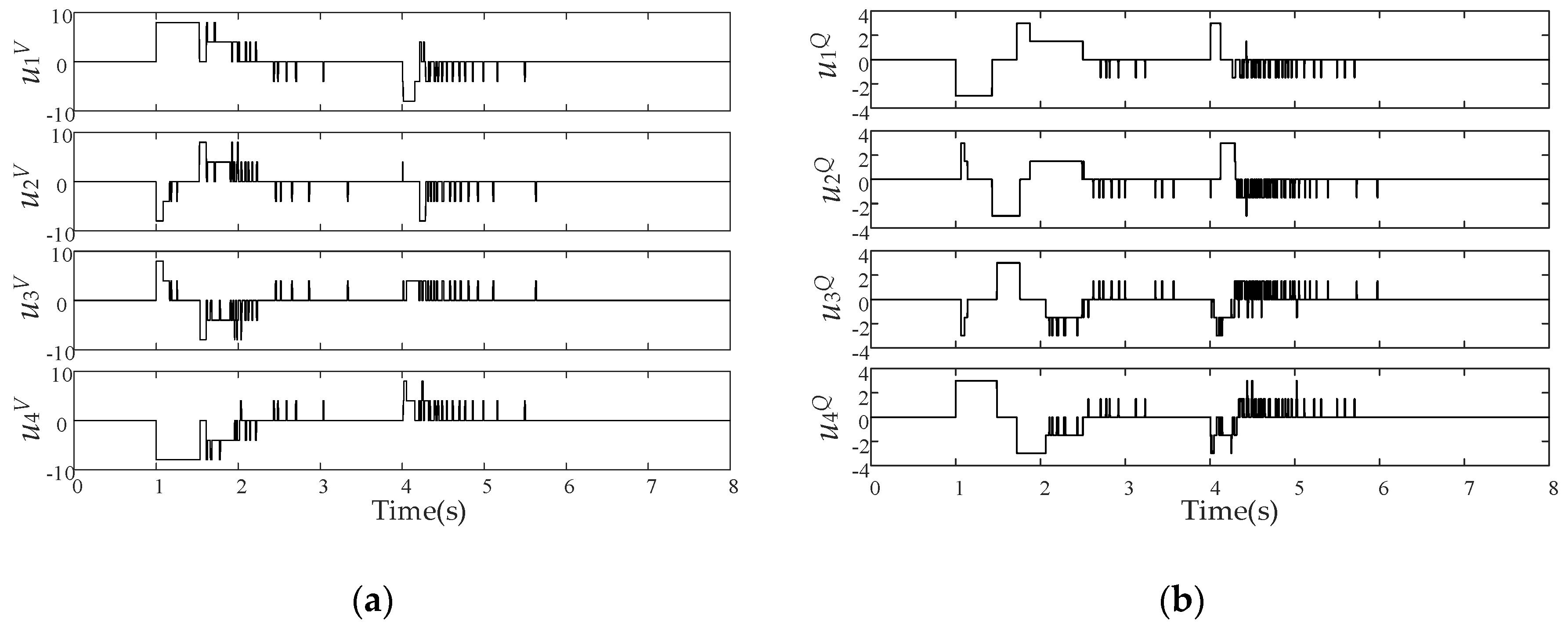
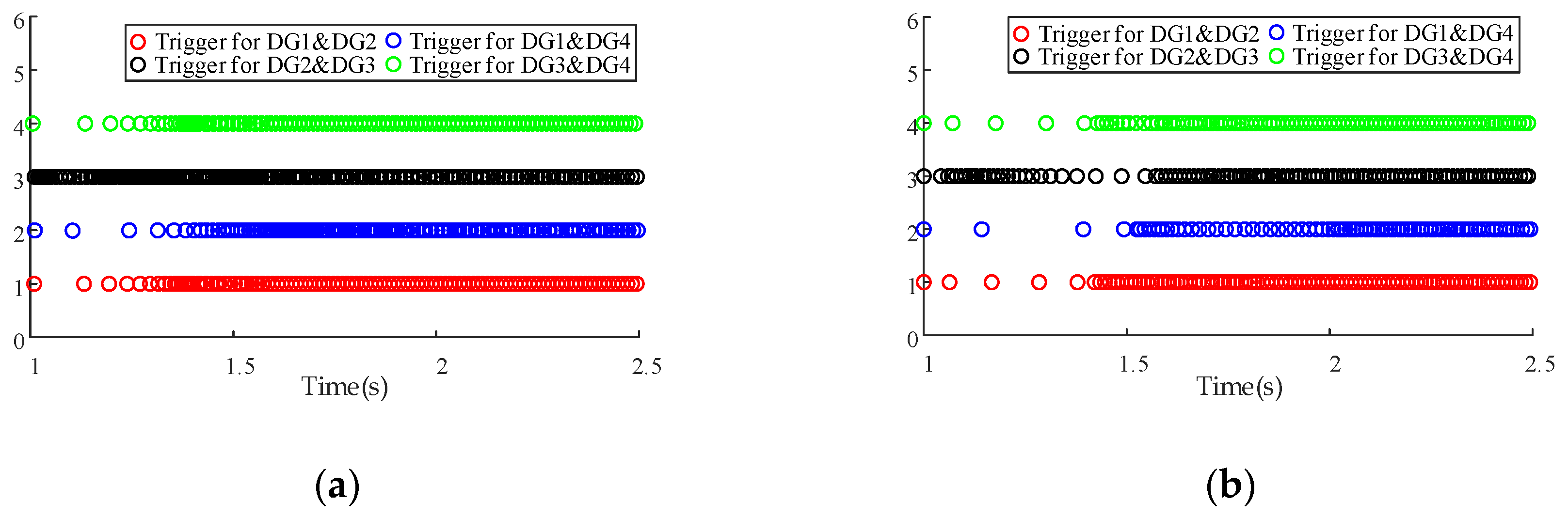
As seen in Figure 6, at the beginning of the simulation, the output voltages of DGs are below the reference value due to the droop-based primary control, and each DG’s reactive power is operating at different output values due to the mismatch of line impedance. When the secondary control is applied at t = 1 s, the average value of voltage and reactive power can be estimated dynamically by our method in a distributed manner. The average voltage can be restored to the nominal value according to the compensation signal while properly sharing reactive power among DGs. Since the value of parameter is selected small enough, the consensus error can be negligible in engineering. When the load changes at t = 4 s, the proposed secondary control scheme can still ensure the control objectives after a transient process. As shown in Figure 7, the proposed ternary self-triggered control law is able to update the control inputs for and at triggering time instants according to the relative state difference between agents. When the consensus is achieved, the control inputs are set to 0 and stop to update. Figure 8 illustrates the triggering time instants of neighboring DGs from 1 s to 2.5 s. As seen in Figure 8, since each linked pair of agents is equipped with a local clock, the neighboring DGs can exchange information independently when the local clock reaches 0. Before the consensus is achieved, the time intervals between the two consecutive triggering time instants are determined by the relative state difference of neighboring DGs. Compared with the conventional continuous-signal-based method, our proposed scheme provides the advantages of reduced communications while meeting the performance requirements of the secondary control.
4.2. Comparison with the Traditional Control Way
The results about microgrid secondary control for average voltage restoration and reactive power sharing are usually based on periodic communication mechanism [9,26]. Therefore, a comparison between the proposed self-triggered control and the traditional control is made in this subsection. The simulation results of the traditional control used periodic communication mechanism are shown in Figure 9. To compare the communication burden with the proposed strategy, for traditional control, periodic communication between neighboring DGs with a 5 ms interval is considered [15]. The comparison results about communication numbers and the average time interval during the time frame 1–2.5 s is depicted in Table 2.
As illustrated in Figure 9, due to the periodic communication mechanism, the voltage and reactive power curves are smoother by using traditional control. The proposed self-triggered control strategy only updates the control inputs according to the triggering conditions which cause a little oscillation in triggering time instants. However, in Table 2, the number of communication transmissions and the average time interval between two contiguous communications show the advantage of the self-triggered strategy compared with the periodic control strategy. It is concluded that, with the proposed self-triggered control strategy, the communication amount between neighboring DGs can be significantly reduced during the operation.
4.3. Plug-and-Play Operation with the Proposed Control Scheme
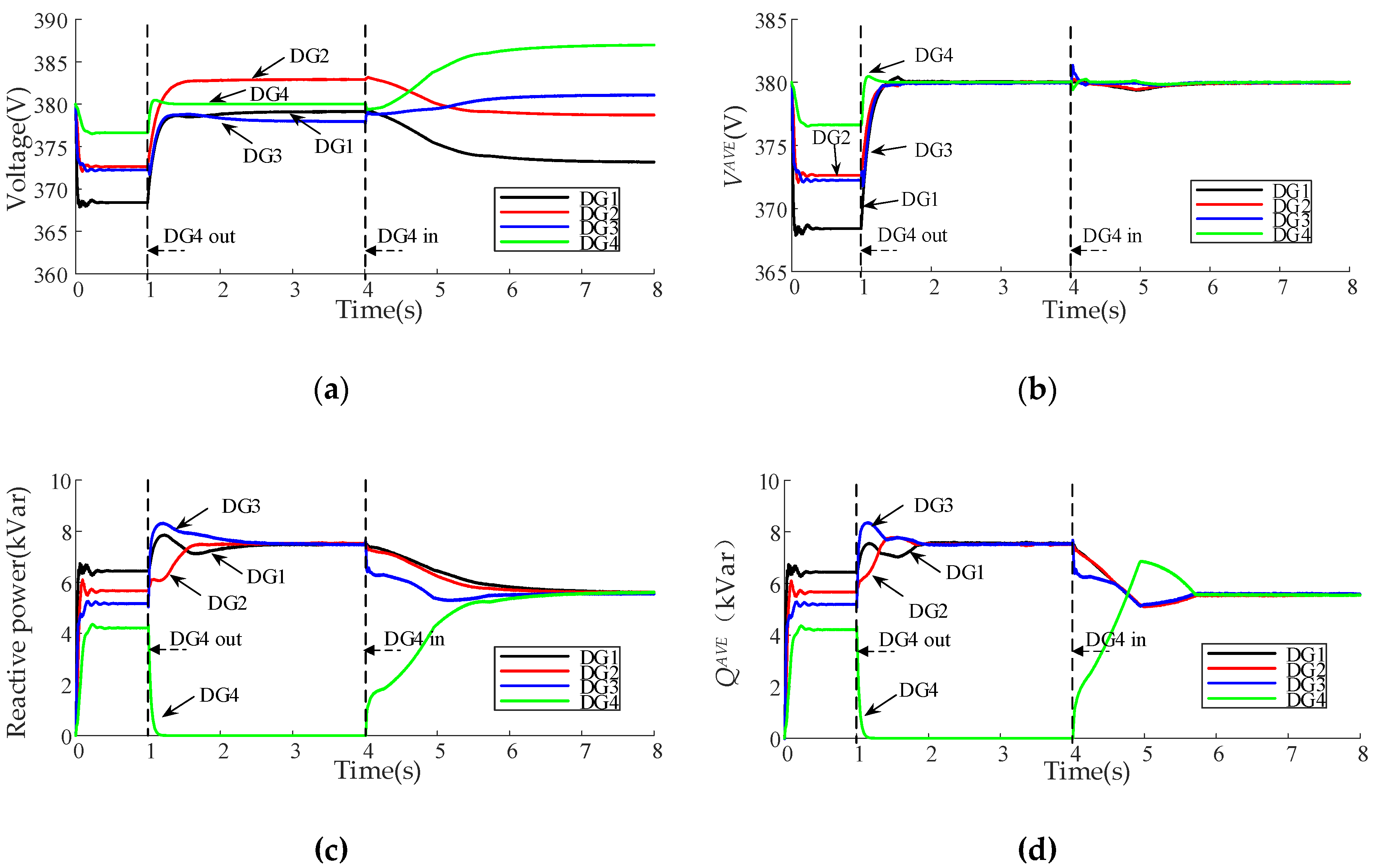
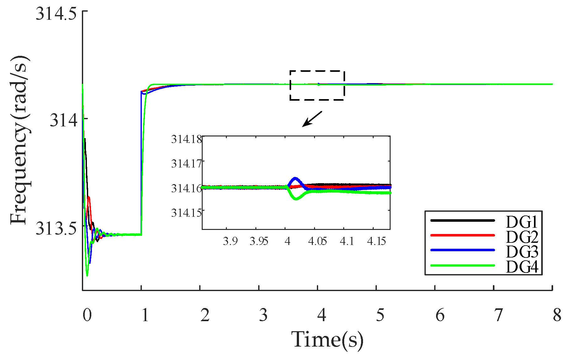
In this case study, the effectiveness of the proposed secondary control scheme under plug-and-play operation is verified. DG4 is plugged out and plugged back at t = 1 s and t = 4 s, respectively. The other simulation process is similar to the case study under load change. The simulation results are demonstrated in Figure 10.
Figure 10 shows the performance of the proposed secondary control scheme when the DG4 occurs plug-and-play operation. After DG4 is plugged out at t = 1 s, its output reactive power drops to 0. Considering that DG4 will be plugged back at t = 4 s, primary control is still activated for DG4 to make its voltage and frequency to meet the requirements of the plug-in operation. A decentralized frequency secondary control scheme (see Appendix A) is also applied at t = 1 s, which ensures all DGs operate at the same frequency when DG4 is plugged back at t = 4 s. While being plugged out, DG4 sends a message to its neighbors and all communication links connected to DG4 are deactivated. Nevertheless, the remaining communication links still contain a connected graph, and the proposed secondary control scheme is able to readjust the reactive power sharing among the remaining DGs while regulating the average voltage to the nominal value. When DG4 is plugged back, it can activate the related communication links and try to find its nearest neighbors by the aforementioned graph discovery algorithm. The simulation results show that our method can properly share the reactive power and achieve the average voltage recovery when DG4 is plugged back. Therefore, the proposed secondary control scheme can restore voltage and realize reactive load power sharing in the case of plug-and-play operation and communication topology changes.
4.4. Effectiveness of the Proposed Control Scheme under DoS Attacks
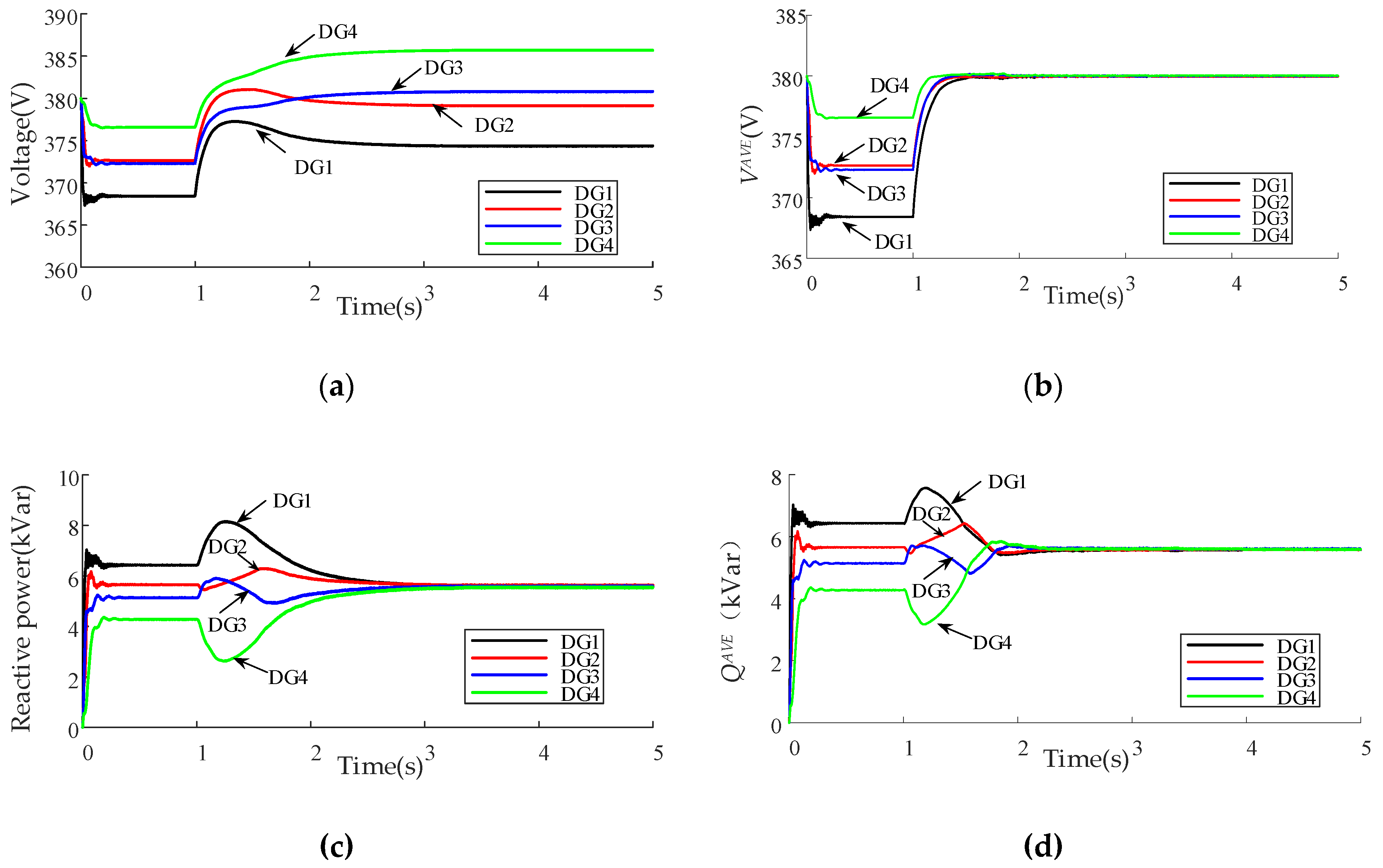
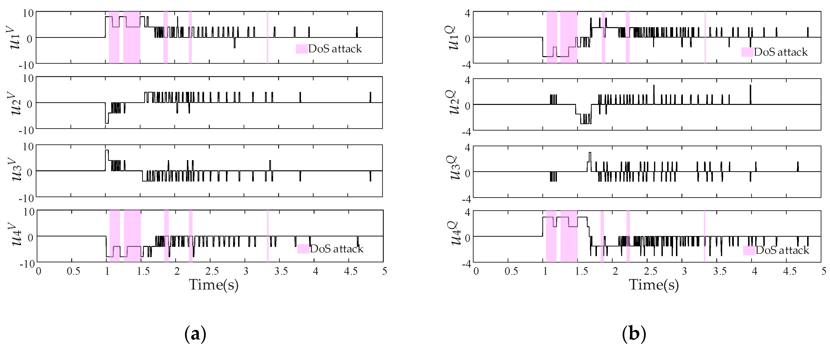
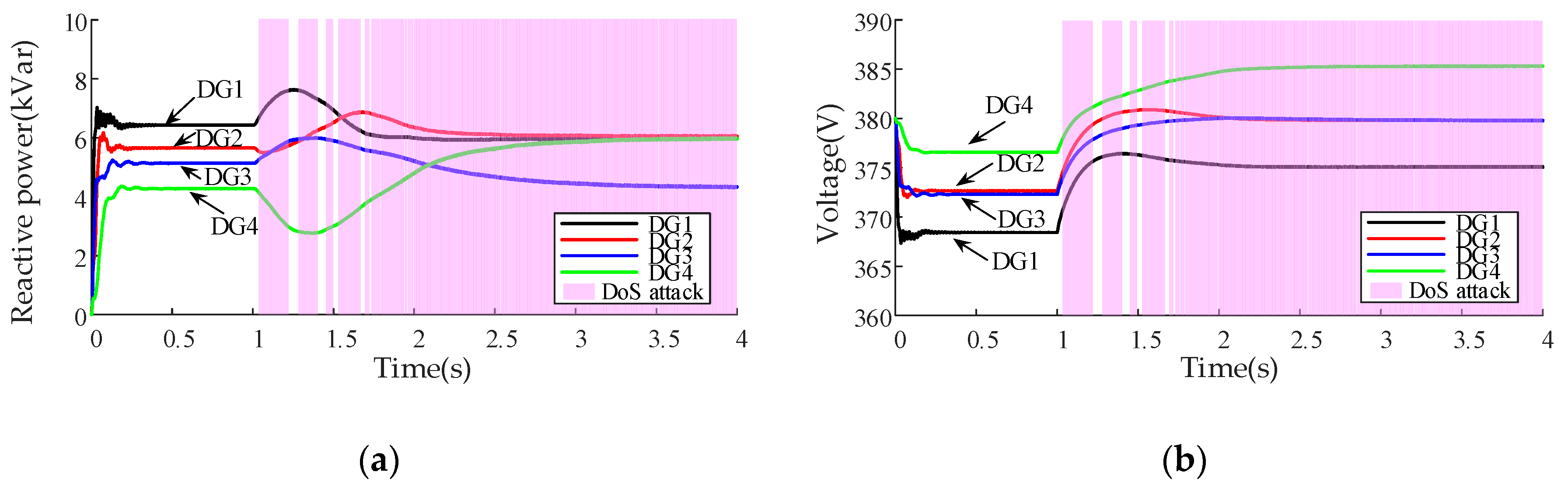
To validate the performance of the proposed secondary control scheme under DoS attacks, the communication link between DG1 and DG4 is supposed to be subject to the attacks after t = 1 s. The simulation results are illustrated in Figure 11, Figure 12 and Figure 13.
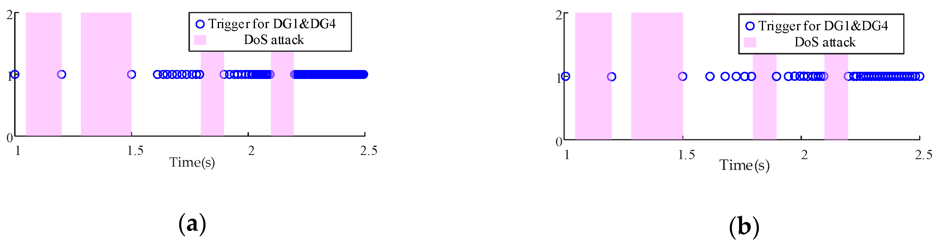
The simulation results in Figure 11 show that the proposed secondary control scheme is able to accurately estimate the average value of voltage and reactive power of overall DGs under DoS attacks, hence achieving the control objectives of voltage restoration and reactive power sharing. Compared with Figure 6, it can be known that DoS attacks weaken the control functions of each agent which increases the convergence time of the proposed strategy. Figure 12 shows that the DoS attacks can block the data transmissions on the communication link between DG1 and DG4. At the triggering time instants, communication attempts between agents are denied by the attack, which leads to the changes of the control inputs for and . Figure 13 illustrates the triggering time instants of DG1 and DG4 under DoS attacks. When DoS attack shifts to a sleep period, the ACK-based monitoring mechanism can detect that the communication link returns to normal, thus the successful communication attempt can be achieved. Our method ensures the immediate update of the control signals and consensus can be ultimately reached. It can be concluded that the control objectives of voltage restoration and reactive power sharing can still be implemented even under DoS attacks.
4.5. Performance Comparison under High-Frequency DoS Attacks
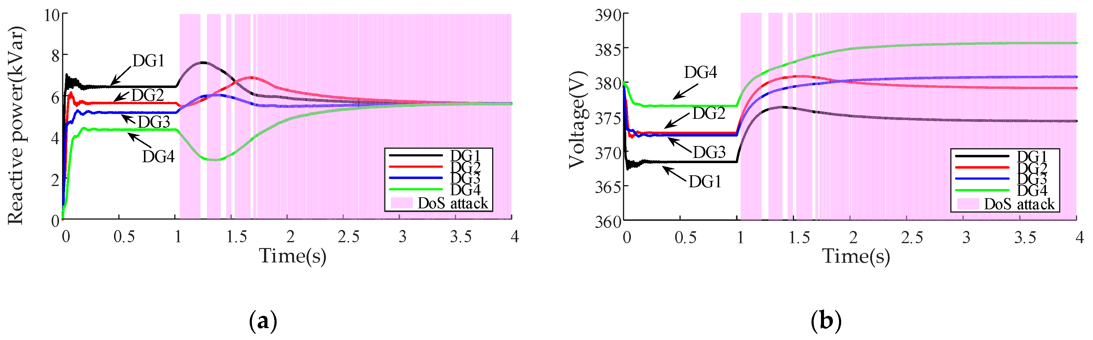
In this subsection, we will make a comparison between our method and the approach described in [32]. It is supposed that the attacker conducts DoS attacks with the same high frequency on the communication links (2, 3) and (3, 4) after the secondary control scheme is applied. The simulation results are shown in Figure 14 and Figure 15.
As can be seen in Figure 14, with the increase of the DoS attacks’ frequency, the secondary control with the approach described in [32] fails to realize proper reactive power sharing among DGs and regulate the output voltages to the wrong values. Since the frequency of the DoS attacks is larger than the frequency of communication attempts between the agents, all transmissions are blocked on communication links (2, 3) and (3, 4), and DG3 becomes an isolated node. Thus, the secondary control scheme becomes invalid since the convergence performance of the approach in [32] is destroyed, and the state observer cannot acquire the correct average information. On the contrary, as seen in Figure 15, our method is more robust to high-frequency DoS attacks, because it can ensure successful information exchanges when the sleep period of attacks is detected. By exploiting the ACK-based monitoring mechanism, the correct average information of voltage and reactive power can be obtained and the proper compensation signal is sent to the primary control level of each DG. Therefore, the consensus of agents can still be achieved and the secondary control objectives can be realized regardless of the DoS attacks’ frequency.
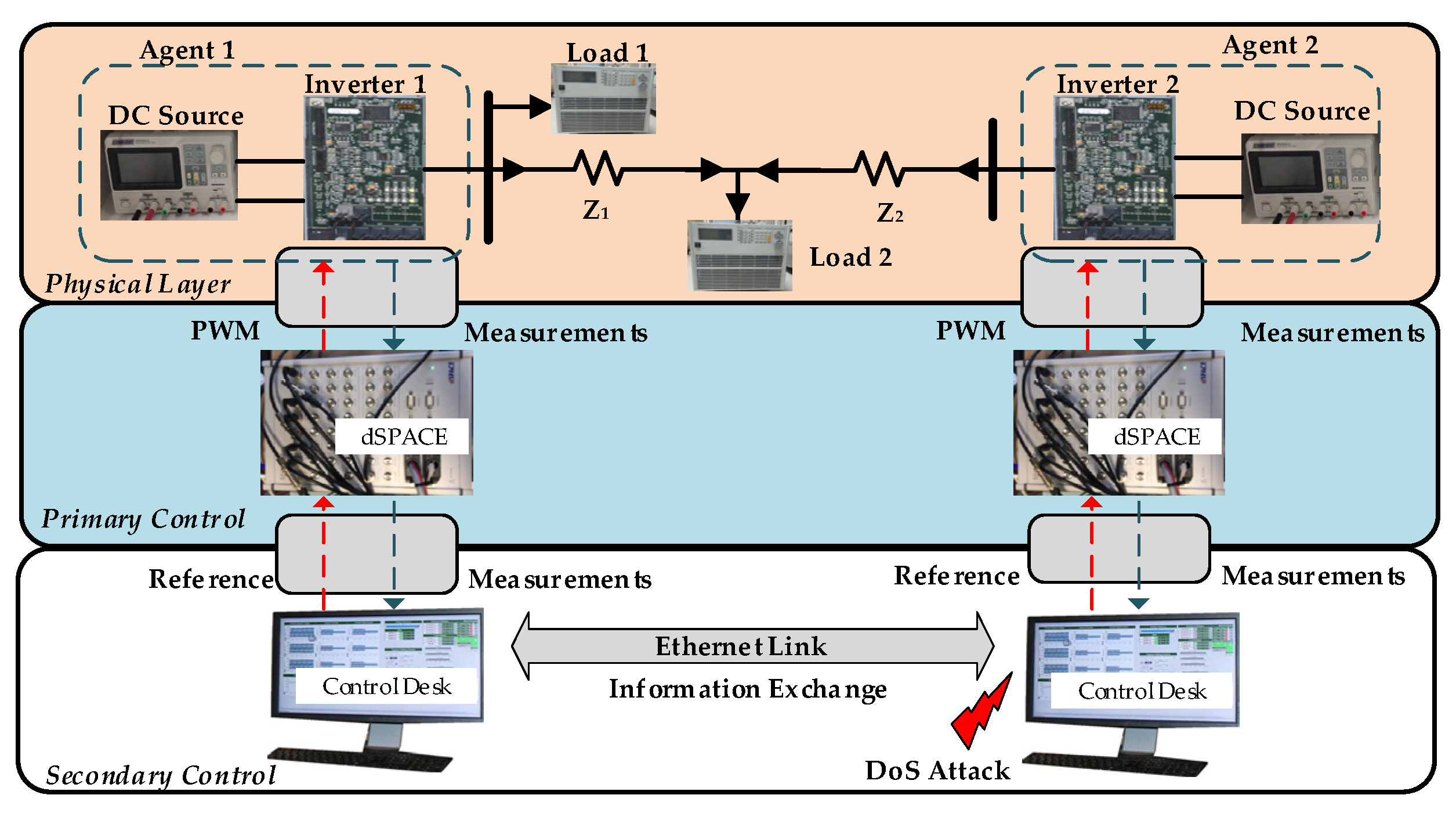
5. Experimental Verification
The proposed resilient control scheme has been experimentally validated in an islanded microgrid testbed with two DG units, as illustrated in Figure 16. The DG1 is included in Setup 1 and DG2 is included in Setup 2. The energy source in the DG unit is represented by a DC voltage source. The inverter is equipped in each setup working as the interfacing power converter between the DG and the loads. In the primary control level, each setup is equipped with a dSPACE Microlabbox board. The primary control loop which is developed using MATLAB/Simulink toolbox is compiled into dSPACE for execution. In the secondary control level, each setup is equipped with a PC platform which runs the dSPACE Control Desk program to manage the dSPACE controller. The PC platform collects the voltage and reactive power information from its local dSPACE and then transmits this information to the other PC using the TCP/IP protocol-based Ethernet links. Using the local and neighboring information, the proposed self-triggered control scheme can be realized on each PC platform to adjust the compensation terms in Equation (7) for each agent to meet the control objective of average voltage restoration and reactive power sharing. It is worth mentioning that the experimental implementation could be simplified by using only one dSPACE and only one PC to control all of the two DGs. However, such implementation conflicts the distributed nature of the proposed control scheme. The experimental testbed parameters are provided in Appendix B.
Since the DoS attack distorts the information exchanges between agents, such an attack is emulated through the on/off commands to the communication port of the PC platform. When the attacker starts to block the information transmission, the communication port of the PC platform in Setup 2 is turned off to emulate such an attack scenario. The real-time detection of such communication failure is not required. At the following triggering time instant, Agent 1 cannot receive the information from Agent 2 which implies that the communication link is in the presence of an attack. Then, the ACK-based monitoring mechanism is activated by Agent 1 to check whether the attack activity shifts to a sleep period. In order to emulate the sleep period of attack, the communication port of Agent 2 is turned on at a certain time instant. Agent 2 can receive the test packets and then send an ACK message to Agent 1. The two agents are able to exchange information and update according to Equations (12)–(14). The experimental results of the proposed control scheme are illustrated in Figure 17 and Figure 18.
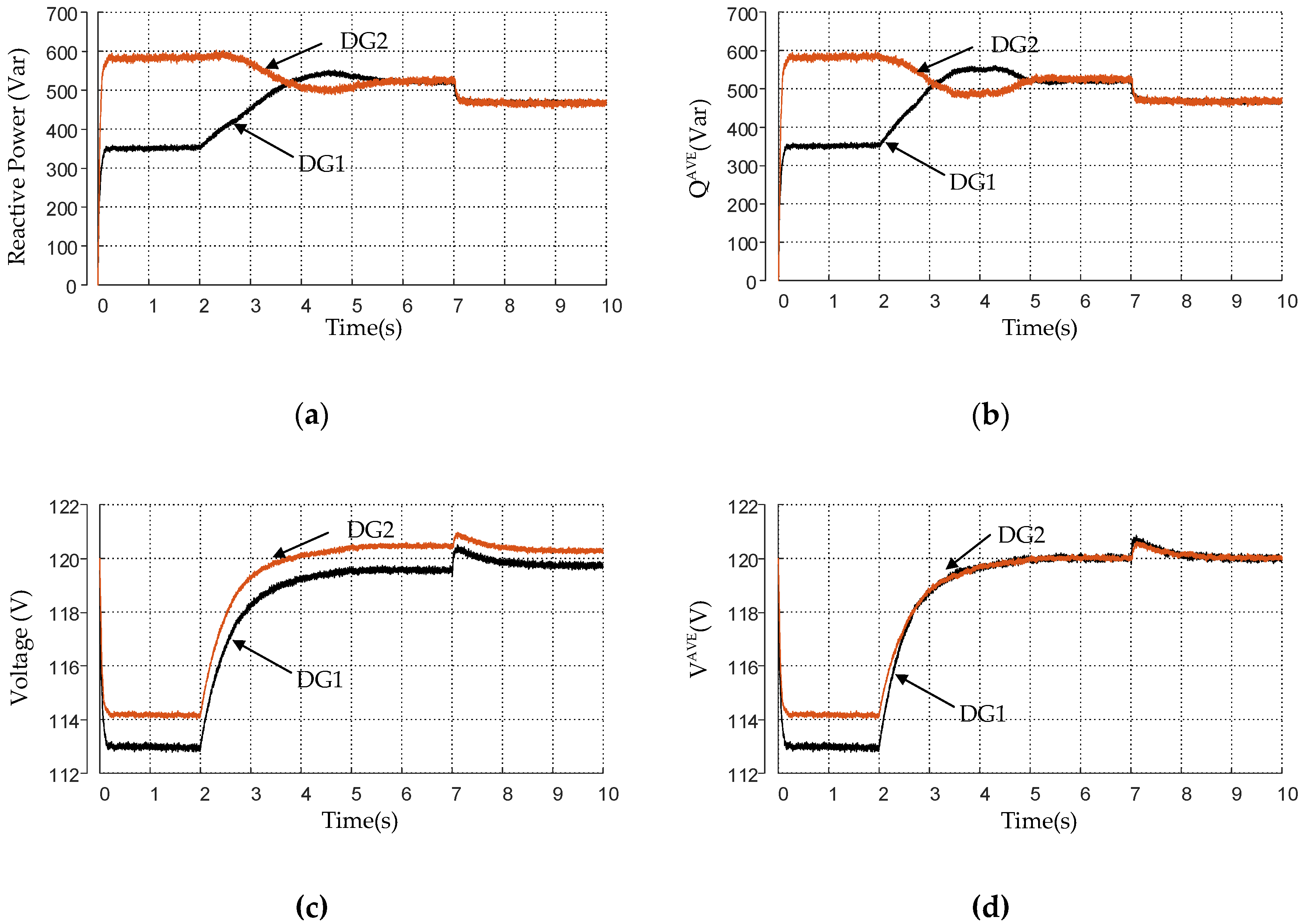
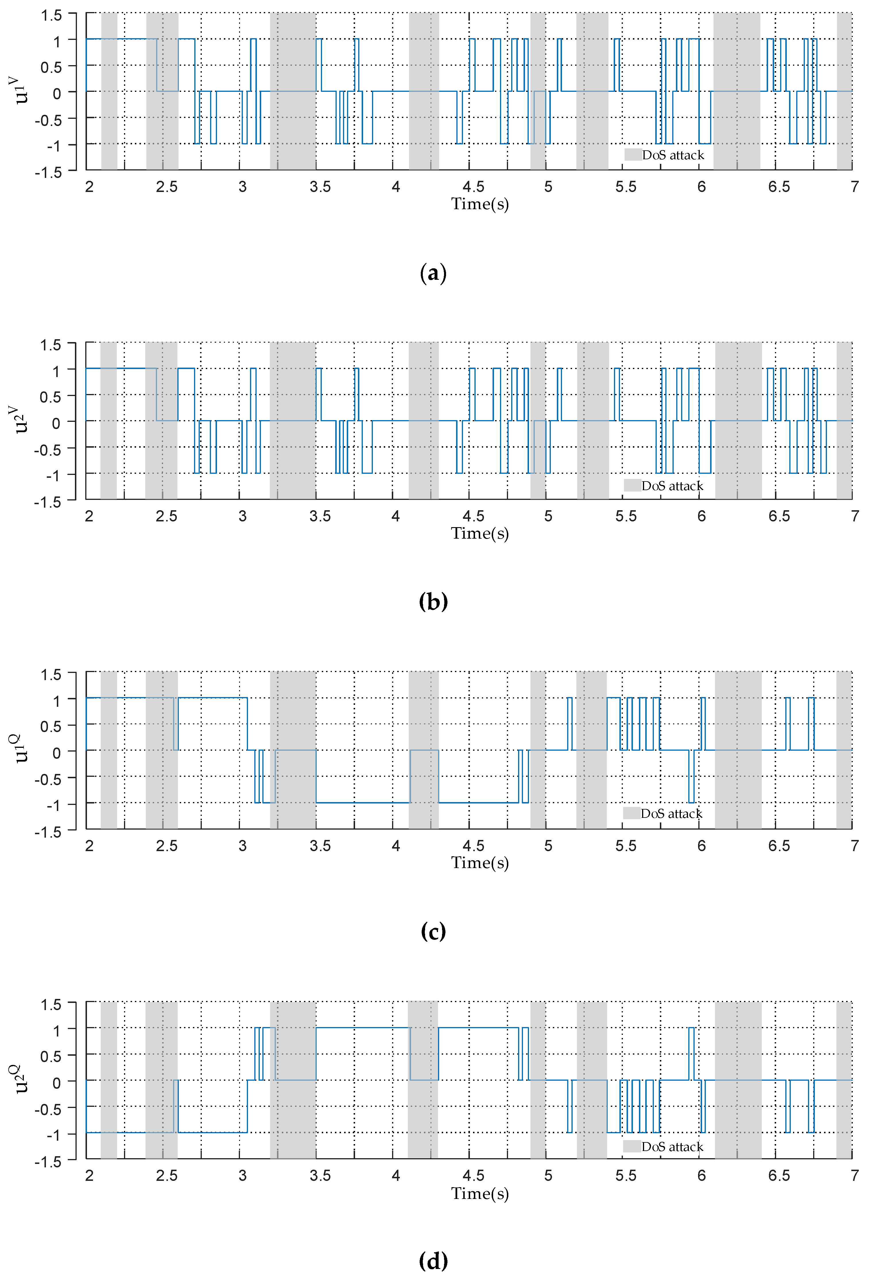
In the experiment, the jamming intervals of DoS attacks are set as { [2.1 s, 2.2 s], [2.4 s, 2.6 s], [3.2 s, 3.5 s], [4.1 s, 4.3 s], [4.9 s, 5.0 s], [5.2 s, 5.4 s], [6.1 s, 6.4 s], [6.9 s, 7.0 s] }. During the jamming intervals, the communication attempts of the two agents are denied by the attack. As can be seen in Figure 17, when the secondary control is applied at t = 2 s, the proposed self-triggered control scheme is able to discover the average information of voltage and reactive power in the presence of DoS attacks. The average voltage of all DGs can gradually restore to the nominal value. Meanwhile, accurate reactive power sharing can be achieved in steady-state. When load1 is decreased by the amount of 100Var at t = 7 s, voltage restoration and reactive power sharing can still be guaranteed after a transient process. Figure 18 shows that the control inputs only update at the triggering time instants and the proposed ACK-based mechanism is able to successfully detect that the DoS attack shifts to a sleep period. Taking the control input as an example, for , is not affected by the attack since there is no triggering time instant during this jamming interval. For , although the attacker starts to block the communication link at t = 2.4 s, changes to 0 at the triggering time instant t = 2.46 s due to the unsuccessful communication attempt between DG1 and DG2. Then, the ACK-based mechanism is activated to check whether the attack shifts to a sleep period. When the attack is cleared at t = 2.6 s, the ACK-based mechanism successfully detects that the communication link returns to normal. Then, DG1 receives the information from DG2 and updates according to the relative state difference between DG1 and DG2 immediately. It can be concluded that the proposed control scheme ensures the immediate update of the control signals when the attack shifts to a sleep period. Thus, the control objectives of voltage restoration and reactive power sharing can still be achieved even under DoS attacks.
6. Conclusions
In this paper, a resilient self-triggered control scheme is proposed for voltage restoration and reactive power sharing in an islanded microgrid under DoS attacks. A state observer with ternary self-triggered control law is constructed to acquire the average estimates of voltage and reactive power of overall DGs while reducing the communication amount effectively. Considering that the adversaries may conduct DoS attacks on the communication network to prevent data transmissions between DGs, an improved ternary control law with an ACK-based monitoring mechanism is proposed, which can ensure the agents to achieve consensus regardless of the frequency of DoS attacks. Thus, the robustness of the proposed control scheme is improved and the secondary control objectives can be ensured even under high-frequency DoS attacks. The simulation and experimental results verify the effectiveness of the proposed control scheme under cases of load changes, plug-and-play operation, and DoS attacks. In future research, we will focus on the improvement of our proposed control scheme, especially the robustness to resist different types of cyber attacks, such as false data injection and replay attacks.
Author Contributions
G.X. provided theoretical guidance. L.M. designed the self-triggered secondary control scheme for the islanded microgrid and did the simulations to verify the effectiveness. All authors have read and agreed to the published version of the manuscript.
Funding
This work was supported by the Fundamental Research Funds for the Central Universities (2019QN111).
Conflicts of Interest
The authors declare no conflicts of interest.
Appendix A
Decentralized frequency control
To compensate for the frequency deviation caused by droop technique, and ensure all DGs operate at the same frequency when DG4 is plugged back, a decentralized frequency secondary control scheme is applied and can be expressed as
where and denote the proportional and integral gains of the PI controller respectively, and here we set and . The dynamic frequency changes of DG1 to DG4 is illustrated in Figure A1.
Figure A1.
Decentralized frequency control for DGs under plug-and-play operation.

Appendix B
Experimental testbed parameters.
Plant: , , , load1 = 200 Var, load2 = 700 Var, , .
Controller: , , , , , , .
References
- Yoldaş, Y.; Önen, A.; Muyeen, S.M.; Vasilakos, A.V.; Alan, İ. Enhancing smart grid with microgrids: Challenges and opportunities. Renew. Sust. Energ. Rev. 2017, 72, 205–214. [Google Scholar] [CrossRef]
- Han, Y.; Zhang, K.; Li, H.; Coelho, E.A.A.; Guerrero, J.M. Mas-based distributed coordinated control and optimization in microgrid and microgrid clusters: A comprehensive overview. IEEE Trans. Power Electron. 2018, 33, 6488–6508. [Google Scholar] [CrossRef] [Green Version]
- Guo, F.; Wen, C.; Mao, J.; Chen, J.; Song, Y.D. Distributed cooperative secondary control for voltage unbalance compensation in an islanded microgrid. IEEE Trans. Ind. Inform. 2017, 11, 1078–1088. [Google Scholar] [CrossRef]
- Han, H.; Liu, Y.; Sun, Y.; Su, M.; Guerrero, J.M. An improved droop control strategy for reactive power sharing in islanded microgrid. IEEE Trans. Power Electron. 2015, 30, 3133–3141. [Google Scholar] [CrossRef] [Green Version]
- Guerrero, J.M.; Vasquez, J.C.; Matas, J.; De Vicuna, L.G.; Castilla, M. Hierarchical control of droop-controlled ac and dc microgrids—A general approach toward standardization. IEEE Trans. Ind. Electron. 2011, 58, 158–172. [Google Scholar] [CrossRef]
- Tan, K.T.; Peng, X.Y.; So, P.L.; Chu, Y.C.; Chen, M.Z.Q. Centralized control for parallel operation of distributed generation inverters in microgrids. IEEE Trans. Smart Grid 2012, 3, 1977–1987. [Google Scholar] [CrossRef] [Green Version]
- Shrivastava, S.; Subudhi, B.; Das, S. Distributed voltage and frequency synchronisation control scheme for islanded inverter-based microgrid. IET Smart Grid 2018, 1, 48–56. [Google Scholar] [CrossRef]
- Khayat, Y.; Naderi, M.; Shafiee, Q.; Batmani, Y.; Fathi, M.; Guerrero, J.M.; Bevrani, H. Decentralized optimal frequency control in autonomous microgrids. IEEE Trans. Power Syst. 2019, 34, 2345–2353. [Google Scholar] [CrossRef]
- Lai, J.; Lu, X.; Li, X.; Tang, R. Distributed multiagent-oriented average control for voltage restoration and reactive power sharing of autonomous microgrids. IEEE Access 2018, 6, 25551–25561. [Google Scholar] [CrossRef]
- He, J.; Li, Y.W.; Blaabjerg, F. An enhanced islanding microgrid reactive power, imbalance power, and harmonic power sharing scheme. IEEE Trans. Power Electron. 2015, 30, 3389–3401. [Google Scholar] [CrossRef]
- Afrasiabi, M.; Rokrok, E. An improved centralized control structure for compensation of voltage distortions in inverter-based microgrids. Energies 2018, 11, 1862. [Google Scholar] [CrossRef] [Green Version]
- Liu, W.; Gu, W.; Sheng, W.; Meng, X.; Xue, S.; Chen, M. Pinning-based distributed cooperative control for autonomous microgrids under uncertain communication topologies. IEEE Trans. Power Syst. 2016, 31, 1320–1329. [Google Scholar] [CrossRef]
- Zuo, S.; Davoudi, A.; Song, Y.; Lewis, F.L. Distributed finite-time voltage and frequency restoration in islanded ac microgrids. IEEE Trans. Ind. Electron. 2016, 63, 5988–5997. [Google Scholar] [CrossRef]
- Simpson-Porco, J.W.; Shafiee, Q.; Dörfler, F.; Vasquez, J.C.; Guerrero, J.M.; Bullo, F. Secondary frequency and voltage control of islanded microgrids via distributed averaging. IEEE Trans. Ind. Electron. 2015, 62, 7025–7038. [Google Scholar] [CrossRef]
- Chen, M.; Xiao, X.; Guerrero, J.M. Secondary restoration control of islanded microgrids with a decentralized event-triggered strategy. IEEE Trans. Ind. Inform. 2018, 14, 3870–3880. [Google Scholar] [CrossRef] [Green Version]
- Fan, Y.; Hu, G.; Egerstedt, M. Distributed reactive power sharing control for microgrids with event-triggered communication. IEEE Trans. Control Syst. Technol. 2016, 25, 118–128. [Google Scholar] [CrossRef]
- Hu, B.; Zhou, C.; Tian, Y.C.; Qin, Y.; Xinjun, J. A collaborative intrusion detection approach using blockchain for multimicrogrid systems. IEEE Trans. Syst. Man Cybern. 2019, 49, 1720–1730. [Google Scholar] [CrossRef]
- Beg, O.A.; Nguyen, L.V.; Johnson, T.T.; Davoudi, A. Signal temporal logic-based attack detection in DC microgrids. IEEE Trans. Smart Grid 2019, 10, 3585–3595. [Google Scholar] [CrossRef]
- Danzi, P.; Angjelichinoski, M.; Stefanovic, C.; Dragicevic, T.; Popovski, P. Software-defined microgrid control for resilience against denial-of-service attacks. IEEE Trans. Smart Grid 2019, 10, 5258–5268. [Google Scholar] [CrossRef]
- Ding, L.; Han, Q.L.; Ning, B.; Yue, D. Distributed resilient finite-time secondary control for heterogeneous battery energy storage systems under denial-of-service attacks. IEEE Trans. Ind. Inform. 2020, 16, 4909–4919. [Google Scholar] [CrossRef]
- Zhi, F.; Hu, G. Secure cooperative event-triggered control of linear multiagent systems under DoS attacks. IEEE Trans. Control Syst. Technol. 2019, 28, 741–752. [Google Scholar]
- Fu, R.; Huang, X.; Sun, J.; Zhou, Z.; Chen, D.; Wu, Y. Stability analysis of the cyber physical microgrid system under the intermittent DoS attacks. Energies 2017, 10, 680. [Google Scholar] [CrossRef] [Green Version]
- Stefanovic, C.; Angjelichinoski, M.; Danzi, P.; Popovski, P. Resilient and secure low-rate connectivity for smart energy applications through power talk in DC microgrids. IEEE Commun. Mag. 2017, 55, 83–89. [Google Scholar] [CrossRef]
- Zambroni de Souza, A.C.; Castilla, M. Microgrids Design and Implementation, 1st ed.; Springer International Publishing: Gewerbestrasse, Switzerland, 2019; pp. 171–193. [Google Scholar]
- Bidram, A.; Davoudi, A.; Lewis, F.L.; Guerrero, J.M. Distributed cooperative secondary control of microgrids using feedback linearization. IEEE Trans. Power Syst. 2013, 28, 3462–3470. [Google Scholar] [CrossRef] [Green Version]
- Shafiee, Q.; Guerrero, J.M.; Vasquez, J.C. Distributed secondary control for islanded microgrids—A novel approach. IEEE Trans. Power Electron. 2014, 29, 1018–1031. [Google Scholar] [CrossRef] [Green Version]
- Spanos, D.P.; Saber, R.O.; Murray, R.M. Dynamic consensus for mobile networks. In Proceedings of the 16th World Congress of International Federation of Automatic Control, Prague, Czech Republic, 3–8 July 2005; pp. 1–6. [Google Scholar]
- Ren, W.; Beard, R.W. Distributed Consensus in Multi-Vehicle Cooperative Control, 1st ed.; Springer: London, UK, 2008; pp. 28–38. [Google Scholar]
- Pelechrinis, K.; Iliofotou, M.; Krishnamurthy, S.V. Denial of service attacks in wireless networks: The case of jammers. IEEE Commun. Surv. Tut. 2011, 13, 245–257. [Google Scholar] [CrossRef]
- Salim, M.M.; Rathore, S.; Park, J.H. Distributed denial of service attacks and its defenses in IoT: A survey. J. Supercomput. 2019, in press. [Google Scholar] [CrossRef]
- De Persis, C.; Frasca, P. Robust Self-Triggered Coordination With Ternary Controllers. IEEE Trans. Autom. Control 2013, 58, 3024–3038. [Google Scholar] [CrossRef] [Green Version]
- Senejohnny, D.; Tesi, P.; De Persis, C. A jamming-resilient algorithm for self-triggered network coordination. IEEE Trans. Control Netw. Syst. 2018, 5, 981–990. [Google Scholar] [CrossRef] [Green Version]
- Cruz, T.; Rosa, L.; Proença, J.; Maglaras, L.; Aubigny, M.; Lev, L.; Jiang, J.; Simões, P. A cyber security detection framework for supervisory control and data acquisition systems. IEEE Trans. Ind. Inform. 2016, 12, 2236–2246. [Google Scholar] [CrossRef]
- Starke, M.; Herron, A.; King, D.; Xue, Y. Implementation of a publish-subscribe protocol in microgrid islanding and resynchronization with self-discovery. IEEE Trans. Smart Grid 2019, 10, 361–370. [Google Scholar] [CrossRef]
- Carl, G.; Kesidis, G.; Brooks, R.R.; Rai, S. Denial-of-service attack-detection techniques. IEEE Internet Comput. 2006, 10, 82–89. [Google Scholar] [CrossRef]
- Aragues, R.; Shi, G.; Dimarogonas, D.V.; Sagues, C.; Johansson, K.H. Distributed algebraic connectivity estimation for adaptive event triggered consensus. In Proceedings of the 2012 American Control Conference, Montreal, QC, Canada, 27–29 June 2012; pp. 32–37. [Google Scholar]
Figure 1.
Block diagram of an inverter-based islanded microgrid.

Figure 2.
The proposed distributed control frame for voltage and reactive power.

Figure 3.
Communication topology and DoS attack sequence.

Figure 4.
Comparison of our algorithm and the method in [32].
Figure 4.
Comparison of our algorithm and the method in [32].

Figure 5.
Block diagram of the islanded microgrid test system.

Figure 6.
Performance of the proposed control scheme under load change: (a) DG output voltages; (b) evolution of the estimated average value of voltage ; (c) DG output reactive power; (d) evolution of the estimated average value of reactive power .
Figure 6.
Performance of the proposed control scheme under load change: (a) DG output voltages; (b) evolution of the estimated average value of voltage ; (c) DG output reactive power; (d) evolution of the estimated average value of reactive power .

Figure 7.
Evolution of control inputs for and under load change: (a) control inputs for ; (b) control inputs for .
Figure 7.
Evolution of control inputs for and under load change: (a) control inputs for ; (b) control inputs for .

Figure 8.
Triggering time instants of neighboring DGs: (a) triggering time instants for average voltage restoration control; (b) triggering time instants for reactive power sharing control.
Figure 8.
Triggering time instants of neighboring DGs: (a) triggering time instants for average voltage restoration control; (b) triggering time instants for reactive power sharing control.

Figure 9.
Performance of the traditional control with periodic communication mechanism: (a) DG output voltages; (b) evolution of the estimated average value of voltage ; (c) DG output reactive power; (d) evolution of the estimated average value of reactive power .
Figure 9.
Performance of the traditional control with periodic communication mechanism: (a) DG output voltages; (b) evolution of the estimated average value of voltage ; (c) DG output reactive power; (d) evolution of the estimated average value of reactive power .

Figure 10.
Performance of the proposed control scheme under plug-and-play operation: (a) DG output voltages; (b) evolution of the estimated average value of voltage ; (c) DG output reactive power; (d) evolution of the estimated average value of reactive power .
Figure 10.
Performance of the proposed control scheme under plug-and-play operation: (a) DG output voltages; (b) evolution of the estimated average value of voltage ; (c) DG output reactive power; (d) evolution of the estimated average value of reactive power .

Figure 11.
Performance of the proposed control scheme under DoS attacks: (a) DG output voltages; (b) evolution of the estimated average value of voltage ; (c) DG output reactive power; (d) evolution of the estimated average value of reactive power .
Figure 11.
Performance of the proposed control scheme under DoS attacks: (a) DG output voltages; (b) evolution of the estimated average value of voltage ; (c) DG output reactive power; (d) evolution of the estimated average value of reactive power .

Figure 12.
Evolution of control inputs for and under DoS attacks: (a) control inputs for ; (b) control inputs for .
Figure 12.
Evolution of control inputs for and under DoS attacks: (a) control inputs for ; (b) control inputs for .

Figure 13.
Triggering time instants of DG1 and DG4 under DoS attacks: (a) triggering time instants for average voltage restoration control; (b) triggering time instants for reactive power sharing control.
Figure 13.
Triggering time instants of DG1 and DG4 under DoS attacks: (a) triggering time instants for average voltage restoration control; (b) triggering time instants for reactive power sharing control.

Figure 14.
Performance of the secondary control with the approach described in [32]: (a) DG output reactive power; (b) DG output voltages.
Figure 14.
Performance of the secondary control with the approach described in [32]: (a) DG output reactive power; (b) DG output voltages.

Figure 15.
Performance of the secondary control with our algorithm: (a) DG output reactive power; (b) DG output voltages.
Figure 15.
Performance of the secondary control with our algorithm: (a) DG output reactive power; (b) DG output voltages.

Figure 16.
Experimental setups of an islanded microgrid comprising two DGs.

Figure 17.
Performance of the proposed control scheme under DoS attacks: (a) reactive power; (b) average estimate of reactive power ; (c) output voltage; (d) average estimate of voltage .
Figure 17.
Performance of the proposed control scheme under DoS attacks: (a) reactive power; (b) average estimate of reactive power ; (c) output voltage; (d) average estimate of voltage .

Figure 18.
Evolution of control inputs for
and under DoS attacks: (a,b) Control inputs for ; (c,d) Control inputs for .
Figure 18.
Evolution of control inputs for
and under DoS attacks: (a,b) Control inputs for ; (c,d) Control inputs for .


Table 1.
Parameter values for simulation.
| DG1&DG2 (45 kVA) | DG3&DG4 (34 kVA) | ||
|---|---|---|---|
| Line 1 | Line 2 | Line 3 | |
| Load 1 | Load2 | ||
| 12kW+15kVar | 15.6kW+7.6kVar | ||
| Secondary control parameters | |||
Table 2.
Communication comparison of secondary control.
| DGs | Controllers | Number of Communications | Average Time Intervals | ||
|---|---|---|---|---|---|
| Traditional Control | Our Method | Traditional Control | Our Method | ||
| DG1&DG2 | Voltage | 300 | 141 | 5 ms | 11 ms |
| Reactive power | 300 | 121 | 5 ms | 12 ms | |
| DG2&DG3 | Voltage | 300 | 165 | 5 ms | 9 ms |
| Reactive power | 300 | 123 | 5 ms | 12 ms | |
| DG3&DG4 | Voltage | 300 | 139 | 5 ms | 11 ms |
| Reactive power | 300 | 106 | 5 ms | 14 ms | |
| DG1&DG4 | Voltage | 300 | 102 | 5 ms | 14 ms |
| Reactive power | 300 | 83 | 5 ms | 18 ms | |
© 2020 by the authors. Licensee MDPI, Basel, Switzerland. This article is an open access article distributed under the terms and conditions of the Creative Commons Attribution (CC BY) license (http://creativecommons.org/licenses/by/4.0/).
Share and Cite
MDPI and ACS Style
Xu, G.; Ma, L. Resilient Self-Triggered Control for Voltage Restoration and Reactive Power Sharing in Islanded Microgrids under Denial-of-Service Attacks. Appl. Sci. 2020, 10, 3780. https://doi.org/10.3390/app10113780
AMA Style
Xu G, Ma L. Resilient Self-Triggered Control for Voltage Restoration and Reactive Power Sharing in Islanded Microgrids under Denial-of-Service Attacks. Applied Sciences. 2020; 10(11):3780. https://doi.org/10.3390/app10113780
Chicago/Turabian StyleXu, Gang, and Liang Ma. 2020. "Resilient Self-Triggered Control for Voltage Restoration and Reactive Power Sharing in Islanded Microgrids under Denial-of-Service Attacks" Applied Sciences 10, no. 11: 3780. https://doi.org/10.3390/app10113780
Note that from the first issue of 2016, this journal uses article numbers instead of page numbers. See further details here.