1. Introduction
Nowadays, 96% of the global hydrogen produced comes from the use of fossil fuels (i.e., natural gas, oil); whereas production from water electrolysis represents only 4% [
1]. Indeed, the cost of hydrogen production by using fossil fuels is smaller than water electrolysis given that current electrolyzers are quite expensive and the cost of electricity as well. However, hydrogen production based on fossil fuels, namely gray hydrogen, suffers from lower purity and higher generation of greenhouse gases [
1]. To face the intensive use and depletion of fossil fuels to respond to hydrogen demands, water electrolysis supplied by renewable energy sources (e.g., wind turbine, photovoltaic) is considered an attractive and promising alternative [
2,
3]. Renewable energy sources combined with water electrolysis come within the scope of the development of environmentally friendly hydrogen production pathways to substitute current hydrogen production based on pollutant fuels. Water electrolysis can produce hydrogen at high gas purity but features high cost (electrolyzer, electricity) and lower energy efficiency due to a high specific energy consumption [
1]. For this reason, energy efficiency, cost of electricity, and water electrolysis systems remain major concern to the development of water electrolysis process at a large scale [
1]. The water electrolysis process consists of using electricity coming from the power grid or renewable energy sources to split pure water into hydrogen and oxygen.
Currently, three types of electrolyzers exist depending on their electrolyte and ions transportation: Alkaline, proton exchange membrane (PEM), and solid oxide (SO) technologies [
1]. Alkaline and PEM technologies are currently available in the market; while SO technology is still under research and development due to its recent introduction in the 1980s [
1]. Alkaline is a mature technology since its operation principle was first introduced more than 200 years ago [
4,
5]. In the 1980s and the 1990s, this technology acknowledged a growing interest in the development of large research projects (kilowatt range) to face the second oil shock. Subsequently, the power range has been extended to megawatt and has allowed the development of this technology at a large scale for industrial applications [
6,
7]. The main advantages are cheaper catalysts, higher lifespan, and gas purity. However, this technology presents several drawbacks from the current density, flexibility, ohmic loss, and operating pressure point of view [
1,
5]. Alkaline electrolyzers are commercially available in a few companies as reported in [
5]. Generally, the manufacturers provide the partial load range for each model. The lower partial load range and current density of alkaline electrolyzers are important issues when coupling with renewable energy sources such as wind energy. Indeed, a part of the capacity for water electrolysis cannot be exploited for hydrogen production [
5]. By comparison, PEM technology has been developed since the 1960s to cope with the above-mentioned issues for alkaline electrolyzers [
1,
2]. Recently, several research projects (lying in the range of megawatts) have been initiated in several countries (e.g., Germany, Norway, Denmark, Thailand, New Zealand, Canada) for power to X, industrial hydrogen supply, and mobility applications [
8,
9]. Furthermore, the power to X concept is considered a promising solution to produce decarbonized hydrogen for industry, power, and transportation [
8,
10]. Compared to alkaline technologies, this technology offers high current density (above 2 A·cm
−2), compactness, small footprint, high efficiency, very thin membrane (i.e., 25–300 µm), high-pressure operation, fast response, and dynamic operation, making it suitable when coupling with renewable energy sources [
1]. However, the main drawback is its cost being relatively high since expensive catalyst materials (e.g., iridium, platinum) are used both at the anode and the cathode; at the moment, it hinders its development at large scale and market penetration. For this reason, one of the most important challenges is to decrease its production cost while maintaining high efficiency [
1].
Alkaline and PEM electrolyzers need to be supplied with DC voltages (from a few to hundreds of volt) and DC currents (from ten to thousands of amp). As a result, the use of AC-DC converters from an AC power supply (power grid, wind turbine) is mandatory [
11]. Currently, for high-current applications, large current rectifiers are required, which are mainly based on two families: Thyristor-based rectifier with hybrid filter (THRF) and diode rectifiers with a DC chopper (CRPF) [
12,
13]. The development of such circuits has been led mainly from the availability of switching devices for power converters suitable for high voltage and high currents as thyristors first and IGBT then. In [
13], the authors have provided a literature survey of rectifiers suitable for industrial applications requiring large currents. Thyristor-based rectifiers and IGBT based chopper-rectifiers are compared from the energy efficiency, power quality, and reliability points of view. The power quality from the power supply point of view (i.e., current harmonic content, power factor) must meet with international standards and requirements (e.g., IEEE 519-2014) [
13]. To decrease the current harmonic content and increase the power factor, compensation solutions must be inserted at the power supply. For instance, in [
12], a 12-pulse thyristor-based rectifier including passive and active filters and a 12-pulse bridge rectifier combined with a three-phase interleaved buck converter are compared in terms of power quality, energy efficiency, cost, and volume. In [
14], a passive filter combined with a distribution static synchronous compensator (DSTATCOM) is developed for a 12-pulse thyristor-based rectifier to enhance the power quality. In [
11], diode and thyristor-based rectifiers (6- and 12-pulse), including on-load tap transformers and hybrid filters, and chopper-rectifiers are discussed from the power quality point of view. These solutions lead up to an increase in cost while reducing energy efficiency. Compared to THRF, CRPFs allow avoiding using compensation solutions since the current harmonic content is smaller and the power factor higher. From the power quality point of view, CRPF offers a good alternative to the use of THRF [
12,
13]. All the above-mentioned circuits are voltage sources; since it is known that in the electrolyzers, the production of hydrogen depends on the current, it is obtained in an indirect way as the difference between the voltage outputs by the converter minus the voltage exhibited by the electrolyzer (activation voltage) divided by the internal resistance.
Recently, in [
15], the authors have investigated the effects of the current ripple coming from conventional thyristor-based rectifiers (6- and 12-pulse) and classic chopper-rectifier on the specific energy consumption of high-power alkaline electrolyzers. The higher the current ripple, the higher the specific energy consumption. Hence, the current ripple must be as small as possible to optimize the specific energy consumption. To perform this analysis, the impedance of the electrolyzer (instead of the DC resistance) versus the frequency has to be considered.
From [
11,
12,
13,
14,
15], these large rectifiers must meet several challenging issues from the power quality, energy efficiency, control, and reliability point of view. From the load side, the AC-DC converter has to be able to supply the electrolyzer with a controlled current to manage energy efficiency and hydrogen production. On one hand, for thyristor-based rectifiers, the electrolyzer current is controlled through the output voltage of the rectifier obtained by adjusting the firing angle [
14]. Since high-voltage are generated, thyristor-based rectifiers are particularly fit for alkaline electrolyzers requiring large currents. On the other hand, for chopper-rectifiers, the electrolyzer can be controlled through its voltage and current [
15,
16]. For small-scale electrolyzers [
17], since the stack voltage range is quite small compared to the current range, it is interesting to control the current to enhance the management of the hydrogen flow rate and energy efficiency.
For low- and medium-power applications, diode rectifiers coupled with DC choppers (buck, interleaved buck converter, stacked interleaved buck converter) are the most suitable [
15,
16]. Power quality, energy efficiency, control, and reliability are not the only issues, but there is also the current ripple generated from rectifiers and DC choppers. By their operation, rectifiers generate low-frequency current ripple (around a hundred of hertz); whereas DC choppers generate high-frequency current ripple [
17,
18,
19]. Recent works have emphasized the negative effects of current ripples from power electronics on specific energy consumption and energy efficiency [
20,
21]. Compared to a classic DC chopper, interleaved DC choppers enable decreasing or canceling the output current ripple while preserving the reliability of the electrolyzers. Furthermore, interleaved DC choppers can continue to supply the electrolyzer without any interruption in case of power switch failures due to their static redundancy [
18].
The first purpose of this article is to review alkaline and PEM electrolyzer technologies to emphasize their main electrical features (voltage, current, power) based on technical data from leading manufacturers. Hence, a clear overview of electrical requirements from alkaline and PEM electrolyzers can be obtained. Then, the second purpose is to present a thorough literature review of AC-DC converters for electrolyzer applications including THRF and CRPF. The advantages and drawbacks for each topology from the power quality, energy efficiency, current ripple, cost, control, and reliability point of view are given. Finally, based on these two previous reviews, a summary is achieved and enables opening a discussion focused on future research directions linked to the current challenges of AC-DC converters for electrolyzer applications. In the authors’ opinion, this survey is useful to assess the state of the art and to stimulate new research in a period in which the scenario is changing due to the use of RES to mitigate CO
2 emissions and to the availability of power switching devices based on wide bandgap semiconductors, which will allow different conversion topologies, improving efficiency with reduced costs, and modifying the scenario of electromagnetic interferences (EMI) [
19,
22,
23,
24,
25,
26].
This article is divided into five sections. After this introduction presenting the current state of the art and reasons to carry out this review work,
Section 2 consists of positioning this review work compared to the current state of the art to highlight the contributions of this article. After that,
Section 3 introduces the principle of operation of alkaline and PEM electrolyzers and the most important features based on commercial electrolyzers. Then, in
Section 4, AC-DC converters including THRF and CRPF with their advantages and drawbacks are presented. Furthermore, each AC-DC converter is compared from the power quality, energy efficiency, current ripple, cost, control, and reliability points of view. Finally, in
Section 5, a discussion is provided regarding the most suitable topologies according to the application and future research directions in using these topologies are introduced.
2. Position of this Review Work Compared to the Current State of the Art
Based on the current literature [
11,
12,
13,
14,
15], two main scenarios can be recognized. The former contains high power plants in which the supply is given by the grid (at low and medium voltage); the electrolyzers are mainly alkaline, and the power conversion AC/DC is obtained by a diode or thyristor-based rectifiers. This configuration does not require a dynamic analysis since the power delivered by the grid is always more significant than the one needed by the plant and alkaline electrolyzers shows a negligible dynamic behavior [
15]; the main issues are related to the harmonics towards the grid and the voltage ripple at the output of the electrolyzer [
17]. By the use of IGBTs instead of thyristors in power converters, harmonics are mitigated, and their impact is lessened since the higher switching frequency of the power devices can be increased, and consequently, the frequency of harmonics is increased too. It makes their suppression easier and minimizes the effect on the electrolyzers. In the above-mentioned power plants, advances are tied to the availability of new power devices suitable for high currents; on the other hand, the topologies of high power converters are well assessed.
The power to gas (P2G) conversion topology, deployed as adjuncts to wind parks or solar-electric generation in which the excess power or off-peak power generated by wind generators or solar arrays may then be used hours, days, or months later to produce electrical power for the electrical grid, is tied to the development to circuits to interface high power wind turbine with the grid [
27]. Since these circuits are not developed expressly for supplying electrolyzers, they are not analyzed in the article.
The contribution of the article aims at focusing the attention on issues and related topologies for energy conversion from a RES to the electrolyzer. The power ranges from a hundred W up to a hundred kW. The main issues are related to the dynamic behavior of the source and of the electrolyzer. Using PEM electrolyzers, dynamic behavior can be recognized and modeled. It influences the modeling of the converter and its control system design as well.
The authors studied these issues considering the dynamic model of a PEM electrolyzers in [
28]; different converter topologies and related control systems have been discussed in [
18,
29] and converters supplied by wind generators in [
16,
30].
These studies are based on the identification of the dynamic model of a PEM electrolyzer; it is a novelty in the literature that allowed the study conversion topologies and related control systems devoted to properly supply the electrolyzer when the power delivered by the source is subjected to variation. For this reason, our proposal is focused on the new methodology proposed by the authors for the first time.
In this field, numerous developments are expected. They are encouraged firstly by the amount of the investments that is lower compared to high power plants and secondly, fast wide-bandgap switching devices are already available, allowing the retrofit of the existing converters and the design of new topologies. As an example, active rectifiers allow minimizing the impact of the converter on the grid or the wind generator. These fast devices can be operated at a higher frequency, assuring an improved efficiency and a reduced size of reactive components (inductors and capacitors), leading to a fast dynamic behavior.
3. Alkaline and PEM Electrolyzers: Operation, Features, and Leading Manufacturers
To cope with global warming and depletion of fossil fuels, hydrogen production based on water electrolysis is an attractive solution. Indeed, hydrogen generated through the water electrolysis process can lead to reducing the carbon footprint, depending strongly on the source of electricity used to supply electrolyzers. On one hand, electricity from the power grid is not the ideal source to supply electrolyzers since most of the electricity is generated by power plants resulting in greenhouse gas emissions (i.e., coal and natural gas-fired power station). On the other hand, renewable energy sources (e.g., wind, solar, hydro energy) offer a viable pathway to meet the growing demand for energy and the global interest in decreasing the carbon footprint. Currently, Iceland, Costa Rica, and Norway use a large part of the electricity generated from hydro, geothermal, and wind energy. However, when using renewable energy sources, intermittent energy discontinuances are generally met. Therefore, energy storage such as hydrogen buffer storage enables easing intermittent power discontinuances by storing excess energy from renewable energy sources at periods of low energy requests and delivering stored energy at periods of high energy request.
Thus, it can ensure a balance between production and consumption. In hydrogen production pathways based on renewable energy sources, produced and stored hydrogen can be employed for various applications as shown in
Figure 1 [
8,
10]:
Transportation: Hydrogen allows supplying hydrogen fueling stations for fuel cell electric vehicles. Hydrogen is stored in pressurized tanks (around 700 bar) and supply PEM fuel cells to power electric motors. Some car manufacturers have even developed fuel cell electric vehicles such as Toyota (Mirai model), Hyundai (Tucson model), and Honda (Clarity model).
Energy storage: To face intermittent energy disturbances, the surplus energy at times of low energy demand can be stored in hydrogen, then used to balance the grid in case of high energy demand.
Power-to-Gas: It consists of converting hydrogen through the methanation process into a green natural gas to be injected in pipeline and underground facilities. It represents an alternative storage capacity, which can be employed where and when it is required most and makes the power system more flexible.
Industry: Hydrogen can be used in different industrial processes such as chemical (e.g., ammonia synthesis, methanol production), metallurgic (e.g., metalworking, carbon steels), and electronic (e.g., semiconductors production).
An overview of strengths, weaknesses, opportunities, and threats within the framework of this review work is given in
Table 1. It is evident that technology is already mature and new improvement is coming using RESs; the new generation of power switching devices, on the other hand, should be sustained by the policy.
In the next subsections, the principle of operation of alkaline and PEM electrolyzers is presented. Furthermore, the most important features for each technology are provided based on technical data from the lead manufacturers of electrolyzers. The electrical requirements to supply the electrolyzer are needed to determine the most suitable AC-DC converter.
3.1. Alkaline Electrolyzers
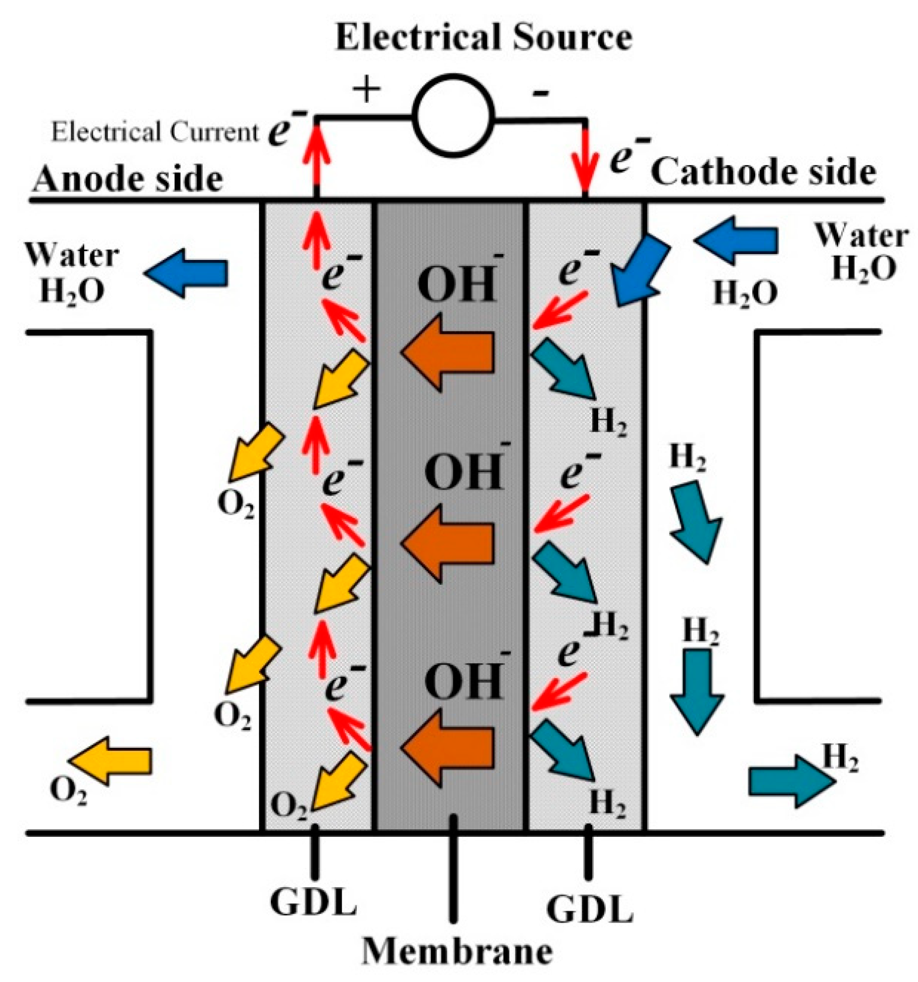
In alkaline electrolyzers, the chemical reaction occurs in an aqueous solution composed of water and potassium hydroxide (25–30% KOH) between two electrodes. These electrodes are located between a diaphragm, separating the generated gases from both electrodes and moving the hydroxide ions (OH
−) from the cathode to the anode. The chemical reactions of the alkaline water electrolysis process are given as [
4]:
From the chemical reaction (1), two water molecules are split into hydrogen and hydroxide ions because of electrons at the cathode. Then, in (2), hydroxide ions travel through the membrane towards the anode where they are combined with electrons to make oxygen. The principle of operation of alkaline water electrolysis is shown in
Figure 2. The main advantages of this technology are mature technology (well-established), cheaper catalysts based on no noble metals (e.g., nickel, cobalt, iron), high long-term stability (exchangeable electrolyte), high hydrogen production rate up to 3880 Nm
3·h
−1 (atmospheric alkaline electrolyzer A3880 from NEL Company, 4.4 mW). However, this technology suffers from having low-current density (leading to bulky electrolyzers) and limited partial load range (impeding its penetration in markets of great potentials such as wind energy) [
4,
5]. Therefore, the remaining challenges for this technology reside in enhancing the current densities, extending the partial load range, and making it more compact. Recently, new and relevant advances in alkaline electrolyzers have been reported such as the use of new electrocatalysts to reduce overpotentials and increase energy efficiency, and new diaphragms to expand partial load range while decreasing ohmic losses [
2,
5].
Nowadays, alkaline electrolyzers are manufactured by a few companies and a summary of the most important specifications for different models is given in
Table 2. Generally, most manufacturers provide specifications such as hydrogen flow rate (Nm
3·h
−1), energy consumption (kWh·Nm
−3), and partial load range (%). From
Table 2, it can be noted that all the manufacturers use electrolyte potassium hydroxide (25–30%). Generally, potassium hydroxide is preferred compared to sodium hydroxide (NaOH) since it is more conductive. The operating pressures of this technology are included between 3 bar and 35 bar. Based on the power of electrolyzer stack (from kW to mW), the range of hydrogen flow rate is between 1.5 Nm
3·h
−1 and 3880 Nm
3·h
−1; whereas the specific energy consumption is between 3.8 kWh·Nm
−3 (H
2) and 5.4 kWh·Nm
−3 (H
2). Another important feature provided by the manufacturers is the partial load range. Indeed, the usual partial load range is included between 40% and 100%; but some manufacturers (e.g., Hydrogenics, NEL) offer a partial load range of 25–100% and 15–100%, respectively. By expanding the partial load range, the manufacturers seek to extend the penetration of alkaline electrolyzers in hydrogen production pathways based on a wind energy conversion system. Hence, the alkaline electrolyzers can exploit the energy supplied by the wind turbine even at low wind speed to produce hydrogen [
31].
On the other side, alkaline electrolyzers feature a slow system response to dynamic operations, particularly important for wind turbines. This slow response is due to the liquid electrolyte used, slowing down the movement of the hydroxide ions from the cathode to the anode [
32]. As a result, the alkaline electrolyzers are not able to absorb the energy during fast intermittent energy discontinuances.
Among all the manufacturers reported in
Table 2, the Norwegian company NEL propose alkaline electrolyzer with the best performance in terms of operating pressure (up to 200 bar), hydrogen flow rate (up to 3880 Nm
3·h
−1), specific energy consumption (3.8–4.4 kWh·Nm
−3), partial load range (15–100%), and stack power (up to 2.2 mW). The A-series (as reported in
Table 2) can use two stacks of 2.2 mW connected in series to increase the power and hydrogen flow rate while decreasing the specific energy consumption and offering a wide partial load range.
3.2. PEM Electrolyzers
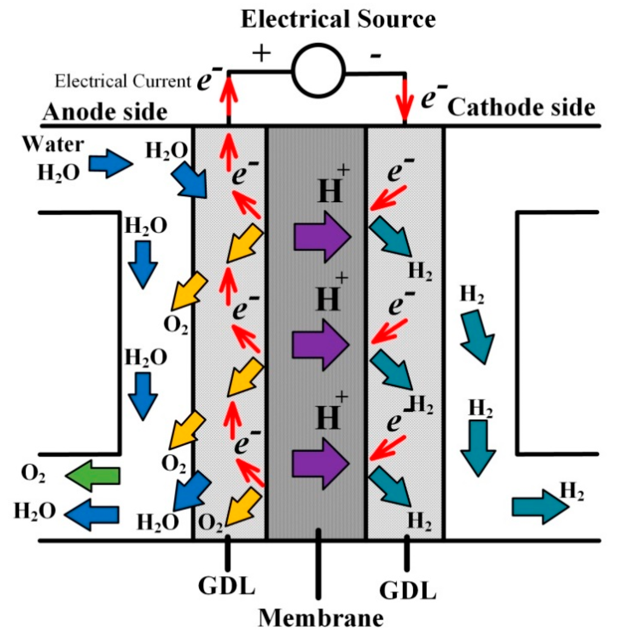
Compared to alkaline electrolyzers, PEM electrolyzers are composed of a solid polymer electrolyte (SPE) that is in charge of the transfer of protons from the anode to the cathode, the separation of the generated gas both at the anode and cathode, and the electrical insulation between both electrodes while acting as a reactant barrier against gas crossover. The chemical reactions of the PEM water electrolysis are summarized below [
1]:
From the reaction (4), the water molecules react at the anode to form oxygen and positively charged protons. After that, in (5), protons pass through the SPE towards the cathode where they are combined with electrons to make hydrogen. The principle of operation of alkaline water electrolysis is shown in
Figure 3. Over alkaline technology, PEM electrolyzers feature higher power densities and efficiency, suitable partial load range, compact stack design, high-pressure operation, and faster dynamic response times. Currently, SPE is based on fluoropolymer (PFSA) Nafion membranes from the DuPont Company, which are the most widespread for this technology since they offer high thermal stability and proton conductivity (i.e., 0.1 S·cm
−1 at 100 °C), and thin membrane (25–254 µm). The choice of the membrane thickness results in a compromise between the expected operating pressures across the membrane, mechanical resistance, low gas crossover, and ohmic resistance [
32]. In [
3,
42], it has been highlighted that the very thin membrane allows decreasing ohmic losses and operating the membrane at high pressure due to its high mechanical resistance. However, the higher the operating pressure, the higher the equivalent current of hydrogen crossover [
43]. As a result, faradaic losses due to the hydrogen and oxygen crossover increase. Faradaic losses related to Faraday’s efficiency are particularly important at low current densities. To overcome this issue, PEM electrolyzers have to operate at medium and high current densities to reduce the Faradaic losses.
The main drawback of this technology is its cost since noble materials (e.g., iridium, platinum) are used for the catalysts both at the anode and cathode. The remaining challenges concern the cost reduction by decreasing and substituting noble materials and cost-intensive components, the enhancement of the long-term stability, and scale-up single cells (>1000 cm
2) [
42].
Like alkaline electrolyzers, PEM electrolyzers are manufactured by a few companies and a synthesis of the most important specifications for different models is given in
Table 3. The same specifications data have been collected to be compared with those for alkaline electrolyzers. All the specifications for different PEM electrolyzer models are summarized in
Table 3. From
Table 3, it can be noted that only three companies (i.e., NEL, GREEN Hydrogen, Hydrogenics) manufacture both alkaline and PEM electrolyzer but with different specifications. The operating pressures of this technology are included between 1 bar and 50 bar due to the thinner membrane enabling operating at higher pressures compared to alkaline technology.
Based on the power of electrolyzer stack (from kW to mW), the range of hydrogen flow rate is between 0.22 Nm3·h−1 and 413 Nm3·h−1; whereas the specific energy consumption is between 4.53 kWh·Nm−3 (H2) and 7.3 kWh·Nm−3 (H2). Like for alkaline electrolyzers, the Norwegian company NEL manufacture PEM electrolyzers with the best performance from operating pressure (up to 30 bar), hydrogen flow rate (up to 413 Nm3·h−1), specific energy consumption (4.53–7.3 kWh·Nm−3), partial load range (0–100%), and stack power (up to 2 mW) point of view. The partial load range of PEM electrolyzers is generally between 0% and 100% making them fit for hydrogen production pathways based on wind turbines. Due to their faster dynamics response time and the large partial load range, they can exploit the energy during operations at low wind speed and particularly absorb the energy in case of fast intermittent energy discontinuances.
However, PEM electrolyzers offer lower performance compared to alkaline electrolyzers from the hydrogen flow rate and specific energy consumption point of view. Indeed, the maximum hydrogen flow rate is 413 Nm3·h−1 (around nine times lower compared to A-series from NEL); whereas the minimum specific energy consumption is 4.53 kWh·Nm−3 (against 3.8 kWh·Nm−3 for A-series from NEL). In summary, further improvements are needed so that PEM electrolyzers can compete with alkaline electrolyzers in terms of hydrogen flow rate, specific energy consumption, and system size.
3.3. State of the Art of the Specifications for Alkaline and PEM Electrolyzers
Based on the technical data collected from each electrolyzer manufacturers, a state of the art of both technologies has been carried out and is reported in
Table 4. This state of the art is updated compared to the previous one introduced in [
2]. From
Table 4, it can be noted that PEM electrolyzers are competitive technologies over alkaline technologies since they can offer a similar cell voltage efficiency and system energy efficiency. Furthermore, the system energy efficiency includes the efficiency of ancillaries such as AC-DC converters mainly based on thyristors, which feature high energy efficiency (around 97%). Hence, the enhancement of energy efficiency for both technologies is a challenging issue. In addition, the required DC current (around 1000 amps) and voltage (100 volts) are obtained by using AC-DC converters, which can be based on thyristors or three-phase diode rectifier connected to a DC chopper. Both types of AC-DC converters present advantages, drawbacks, and must face new challenges that are discussed in the next section. Finally, on one hand, in terms of lifetime, alkaline electrolyzers offer more prospective compared to PEM electrolyzers. On the other hand, the understanding of the interactions between AC-DC converters and electrolyzers is a key issue particularly from the life span point of view.
Recent works [
20,
21] have emphasized the effect of current ripple from AC-DC converters on energy efficiency and specific energy consumption, but further investigations are requested to analyze the degradation of electrolyzer performances, providing crucial information about their lifetime.
4. AC-DC Converters for Electrolyzer Applications
Many types of AC-DC converters can be used to supply alkaline and PEM electrolyzers according to their electrical requirements from the current and voltage point of view. From
Table 4, it can be noted that the requested stack voltage can vary from a few to hundreds of volt; whereas the current is included between 10 to thousands of amps, depending strongly on the rated power of the stack (i.e., from watt to megawatt range). Before choosing the right AC-DC converter topology for a given electrolyzer application, different requirements and specifications must be taken into consideration.
The main current issues for the AC-DC converters are summarized below [
13,
18,
20,
21]:
To deliver a controlled DC current to manage the hydrogen flow rate and energy efficiency of the electrolyzer.
Interaction with the power supply from the power quality point of view (e.g., high power factor, compensation of reactive power).
Input current harmonics injected in the AC power supply must meet the international standards and requirements such as IEEE 519-2014.
High efficiency.
High reliability to ensure a continuity of service in case of electrical failures.
Small low- and high-frequency current ripple to extend electrolyzer life span while optimizing the specific energy consumption.
Low cost to reduce the global cost of the system.
In the next subsections, several AC-DC topologies (i.e., uncontrolled, controlled diode and thyristor-based rectifier, and diode bridge rectifiers connected to DC chopper) are provided with their advantages and drawbacks. Furthermore, each AC-DC topology is discussed from the power quality, energy efficiency, current ripple, cost, control, and reliability point of view.
This thorough analysis aims at emphasizing the most suitable AC-DC converter topology for a given application (i.e., low, medium, or high power) and the remaining challenges to overcome some issues for electrolyzer applications.
4.1. Uncontrolled Rectifiers
This subsection aims at introducing uncontrolled based-diode rectifiers (i.e., 6- and 12-pulses). Even though these AC-DC topologies do not meet the first requirement from the current control point of view, this subsection can be considered a starting point to highlight the advantages and drawbacks before presenting controlled based-thyristor rectifiers (i.e., 6- and 12-pulses) and AC-DC converters based on the combination of a rectifier and DC chopper. The technology of AC-DC converters is driven by industrial processes in the metal and chemical industries. Starting with electro-mechanical rectifiers and passing through mercury-arc rectifiers, the availability of static semiconductor power switches (diodes and thyristors and then IGBT) has led the technology from variable DC voltage rectifiers towards converters with fixed DC bus front end rectifier and high-frequency switching stage. A further step will consist of the adoption of active front end rectifiers. The uncontrolled AC-DC converters presented in the following show a fixed DC voltage output; in any case, both the main applications of high power rectifier (arcing loads and electrolyzers) require a voltage regulator. In particular, the load characteristic of electrolyzers, defined by the area comprised between the top load line (TLL) and bottom load line (BLL), is more binding since the voltage variation is restricted. The regulation of the output voltage can be achieved by mechanical on-load tap changing (OLTC) transformers or saturable inter-phase transformers at the expenses of higher maintenance costs and low dynamics (order of seconds). For the sake of simplicity, OLTC and saturable inter-phase transformers are not sketched in the figures.
Compared to single-phase diode rectifiers, which are suitable for low and medium power applications, the three-phase diode bridge rectifier is particularly fit for high power applications (i.e., >15 kW) [
54]. The architecture of this topology is shown in
Figure 4, which is composed of six diodes. The anode of the diodes (i.e.,
D1,
D3, and
D5) are connected to a phase of the AC power grid based on a three-phase delta transformer. In a specific phase, the diode can conduct if the AC voltage on this phase is higher than that on the two other phases. Compared to the classic single-phase diode bridge rectifier, each diode conducts during an angle of 2
π/3 instead of
π (where the conduction angle is calculated considering 2
π the period of grid pulsation).
The average value of the output voltage,
Vel, is given by the following expression [
54]:
where
Vmax is the maximum line-to-neutral voltage in (V). Regarding the
RMS value of the electrolyzer voltage, it is given by [
54]:
It can be noted that the mean value and the
RMS value are almost equal. The main advantages of this topology are its cheap cost, good rectification ratio and form factor, small ripple factor (around 4.2%), and good energy efficiency due to commutation at line frequency. Since the output voltage ripple is quite low, no bulk additional filter is required [
54]. The frequency of the output voltage is six times higher than the input frequency. Furthermore, the power quality of the AC power supply can be ensured with a good power factor and reduced current harmonic content. However, this topology can deliver only a constant output voltage and current to supply the electrolyzer, of which the value depends on the electrical features of the AC power supply and the electrolyzer as well. If the AC power supply was based on a wind turbine conversion system, the output voltage of the rectifier would fluctuate according to the wind speed. For this reason, uncontrolled diode-based rectifiers directly coupled with an electrolyzer are not considered for this application.
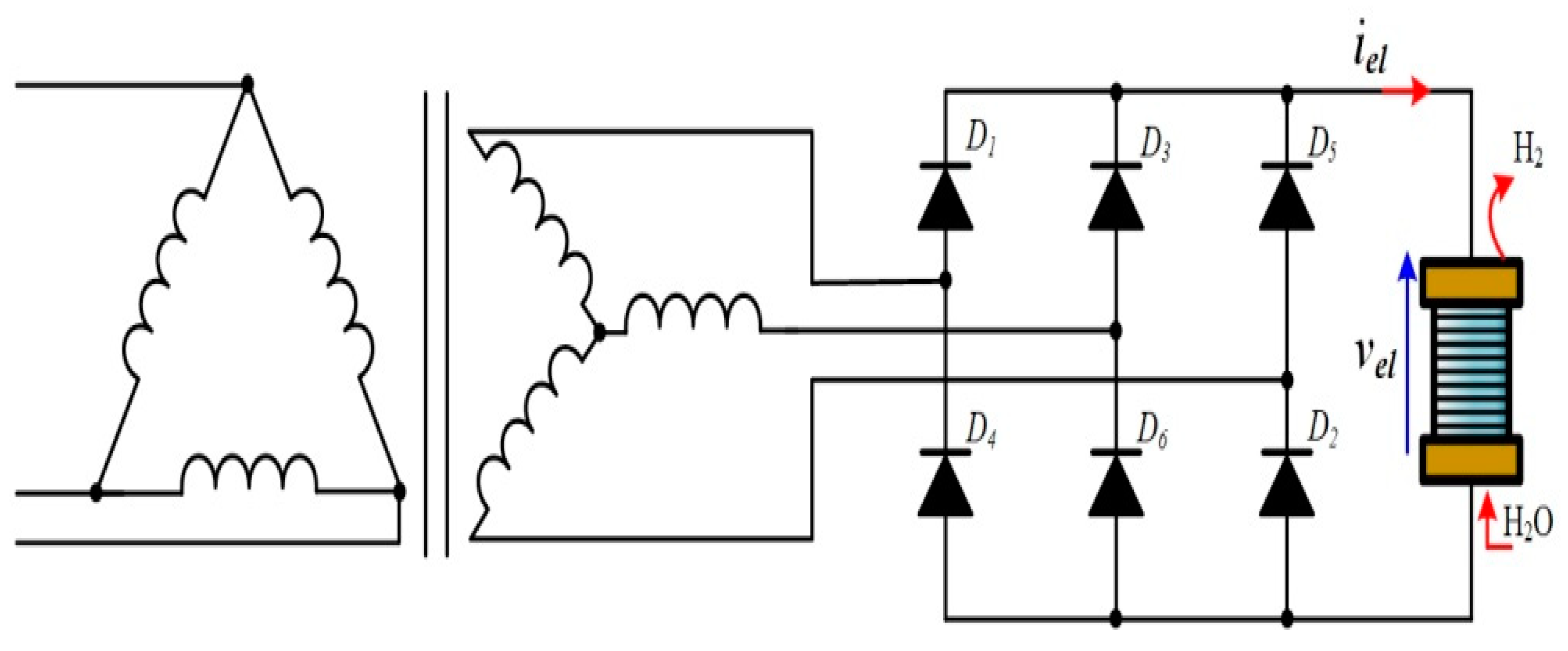
4.1.1. 12-Pulse Diode Bridge Rectifier
Based on
Figure 4, a 12-pulse diode bridge rectifier is shown in
Figure 5, composed of two six-pulse diode bridge rectifiers [
11]. Instead of using one secondary of the transformer (
Figure 4), two secondaries are used, one connected in delta (upper part) and the second one in star (lower part). The two secondaries lead up to a natural shift of
π/6 between the generated voltages to supply the two six-pulse diode bridge rectifiers connected in parallel. The parallel configuration allows for increasing the output current; while the series configuration enables increasing the output voltage [
11]. The choice of the configuration is guided by the electrical specifications of the electrolyzer.
In a parallel configuration, an inter-phase transformer must be used. Indeed, as emphasized in [
54], the inter-phase transformer aims at making the output voltage,
vel, to be the average of the rectified values
v1 and
v2. The frequency of the output ripple voltage is 12 times higher than the input frequency. The average and
RMS output voltage are given respectively by the expressions (7) and (8).
On the other side, in a series configuration, the average value of the output voltage,
Vel, is given by the following expression [
54]:
Concerning the
RMS value of the electrolyzer voltage, it is expressed by [
54]:
Compared to a classic six-pulse diode bridge rectifier, this topology offers a good rectification ratio and form factor, low ripple factor (around 1%), and losses [
54]. In addition, from the power quality point of view, a good power factor and low current harmonic content are provided. However, the complexity of the topology leads to an increase in its cost as well as volume [
11].
4.1.2. Six-Pulse Diode Double-Star Rectifier
For low-voltage applications, a six-pulse diode double-star rectifier can be used as shown in
Figure 6. This configuration is based on two three-phase star rectifiers in which their neutral nodes are interconnected to an inter-phase transformer [
11]. This interphase transformer has the same function as that introduced for the 12-pulse diode bridge rectifier.
The main benefit of using this configuration compared to the classic configuration in
Figure 4 is the decrease of the diode average and
RMS current (i.e., 50% lower). As a result, improved energy efficiency can be obtained [
54]. Furthermore, it offers the same advantages and drawbacks as the classic configuration.
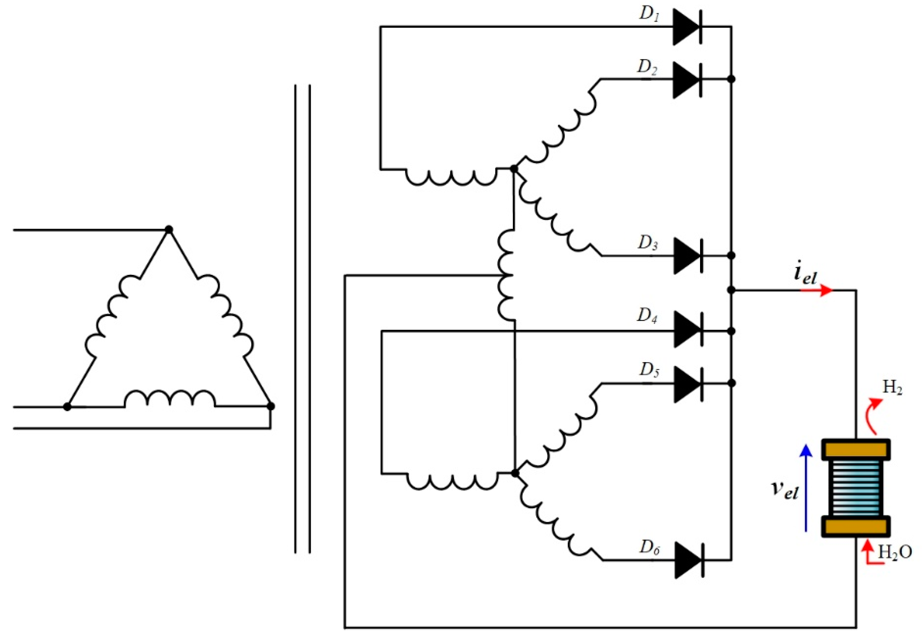
4.1.3. Single-Way 12-Pulse Diode Double-Star Rectifier with Inter-Phase Transformers
Based on the six-pulse diode double star rectifier, two can be coupled in parallel to build a 12-pulse diode double-star rectifier as shown in
Figure 7 [
13].
Like in
Figure 6, the neutral nodes of the two double-star rectifiers are connected by using two inter-phase transformers (i.e., inter-phase transformers). An additional inter-phase transformer is used to link the two inter-phase transformers and the negative polarity of the electrolyzer [
54].
Compared to the six-pulse diode double-star rectifier, this configuration offers lower diode average and
RMS current (i.e., 50% lower [
54]). Thus, energy efficiency is enhanced. However, the complexity of the converter makes it unattractive for this application.
4.2. Controlled Rectifiers
At the present moment, thyristor-based rectifiers dominate the market for industrial applications where a high voltage and current are required to supply electrolyzers [
15,
55]. Compared to the rectifiers based on diodes, the use of thyristors allows delivering a controlled current, needed to manage the hydrogen flow rate and energy efficiency of the electrolyzer when coupling with renewable energy sources. On one hand, the control of thyristor-based rectifiers is carried out through their firing angle. If their firing angle is lower than
π/2, the rectifier operates in rectifier mode; whereas for a firing angle between
π/2 and
π, the rectifier operates in inverter mode [
54]. However, in controlling the rectifier through firing angles, it leads to the increase of current harmonic content and a decrease of the power factor due to the generation of reactive power [
11,
13]. The enhancement of the power quality for thyristor-based rectifiers is a challenging issue. For this reason, the compensation of the generated reactive power is mandatory to increase the power factor. In this subsection, different types of thyristor-based rectifiers are introduced and discussed from the power quality point of view.
4.2.1. Six-Pulse Thyristor Bridge Rectifier
A six-pulse thyristor bridge rectifier is shown in
Figure 8, where the diodes are replaced by thyristors to obtain a variable DC output voltage to supply the electrolyzer. The operation principles of this topology can be found in [
54].
By neglecting the parasitic elements of the thyristors and considering a DC constant current, the average value of the output voltage,
Vel, is given by the following expression according to the firing angle
α [
54]:
From the Equation (11), the maximum DC output voltage (Vel = 538 V if Vrms = 230 V) is obtained for α = 0°, providing the same output voltage as a six-pulse diode bridge rectifier. The higher the firing angle, the lower the DC output voltage. To maintain an operation in rectifier mode, the firing angle cannot be higher than α = 90°.
Despite the fact that this six-pulse thyristor bridge rectifier offers high energy efficiency and a controlled current, it suffers from different drawbacks in terms of power quality and current ripple. Indeed, the generation of reactive power is directly linked to the firing angle. The higher the firing angle, the higher the current harmonics content, drastically decreasing the power factor of the system. Furthermore, based on the work reported in [
55], this topology has a high ripple factor, between 14% and 71%; depending strongly on the load range. The higher the load, the lower the current ripple. For this reason, operation at low load must be avoided. However, the improvement of power quality remains a key issue. In [
15,
21,
55], the authors have demonstrated that high current ripple increases the specific energy consumption, meaning that lower hydrogen quantity is produced based on the same amount of input energy. The current ripple has also an influence on the hydrogen gas quality generated by electrolyzers [
55]. The current ripple can be reduced by using passive filters (i.e., inductor, capacitor) located between the rectifier and the electrolyzer, and/or the use of other AC-DC converters (e.g., 12-pulse thyristor-based rectifier, rectifiers plus DC chopper). Output passive filters have been introduced in [
55,
56].
On the other side, to improve the power factor by compensating the reactive power, different solutions have ever been proposed in the literature. This rectifier generates odd rank harmonics (i.e., 5, 7, 11, 13, 17, etc.). The most widespread solution is to use passive filters (AC power supply side), which are designed and tuned to cancel a specific harmonic frequency. Another solution is to employ STATCOMs (i.e., static compensator) or DSTATCOMs (i.e., distribution static compensator) [
11,
21]. This solution is fit for variable reactive power compensation. However, the use of these devices leads to increases in; the cost and losses. To overcome the cost issue, hybrid solutions have been proposed combining passive filters and STATCOMs [
11].
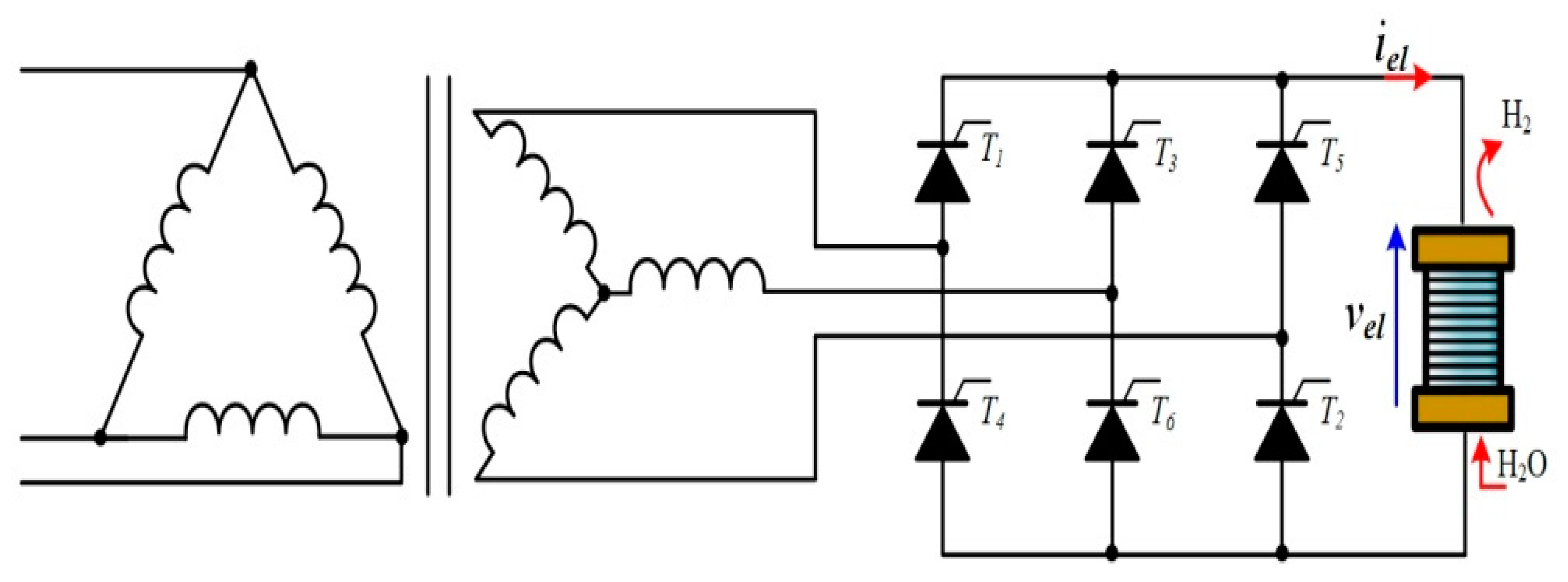
4.2.2. 12-Pulse Thyristor Bridge Rectifier
To face the power quality and current ripple issues, a 12-pulse thyristor bridge rectifier can be used as shown in
Figure 9. It is depicted in a parallel configuration with an inter-phase transformer to increase the output current but can be configured in series to increase the output voltage. The two secondaries are coupled either in delta (upper part) or in star (lower part). The two secondaries offer a natural shift of
π/6 between the generated voltages. In a parallel configuration, this topology is particularly suitable for electrolyzers requiring a high current as reported in
Table 4.
This topology features several benefits over the six-pulse thyristor bridge rectifier from the power quality and current ripple points of view. Indeed, on one hand, as emphasized in [
55], the ripple factor is lower, between 3.2% and 4.8% according to the load range. Thus, the specific energy consumption is lower and the quality of the produced hydrogen is better. On the other hand, despite the reduction of the specific energy consumption, it is still higher than the reference of specific energy consumption at pure DC current [
15].
Finally, a 12-pulse thyristor bridge rectifier enables eliminating odd rank harmonics, consequently reducing the reactive power and increasing the power factor. However, to meet the international standards and requirements such as IEEE 519-2014 (providing recommended harmonic limit for current distortion), a hybrid filter composed of shunt passive filter and DSTATCOM has been proposed and discussed in [
14]. Thanks to this hybrid filter, an input power factor of 0.98 and a low THD (total harmonic distortion) of 4.8% are obtained.
4.2.3. Six-Pulse Thyristor Double-Star Rectifier
For high-current applications and to eliminate harmonics, a six-pulse thyristor double-star rectifier can be employed, as shown in
Figure 10. The two thyristor-based rectifiers are shifted by 180°, and their secondary neutral nodes are interconnected through an inter-phase transformer. It is connected between the two secondary neutral nodes and the negative polarity of the electrolyzer [
54].
The main advantage of using this double-star rectifier compared to the basic configuration in
Figure 8 is the decrease of the thyristor average and
RMS current (i.e., 50% lower) and output current ripple as well. Therefore, the specific energy consumption is enhanced and the quality of the hydrogen produced is optimized. From the power quality point of view, by the reduction of current harmonic content, the power quality can be improved.
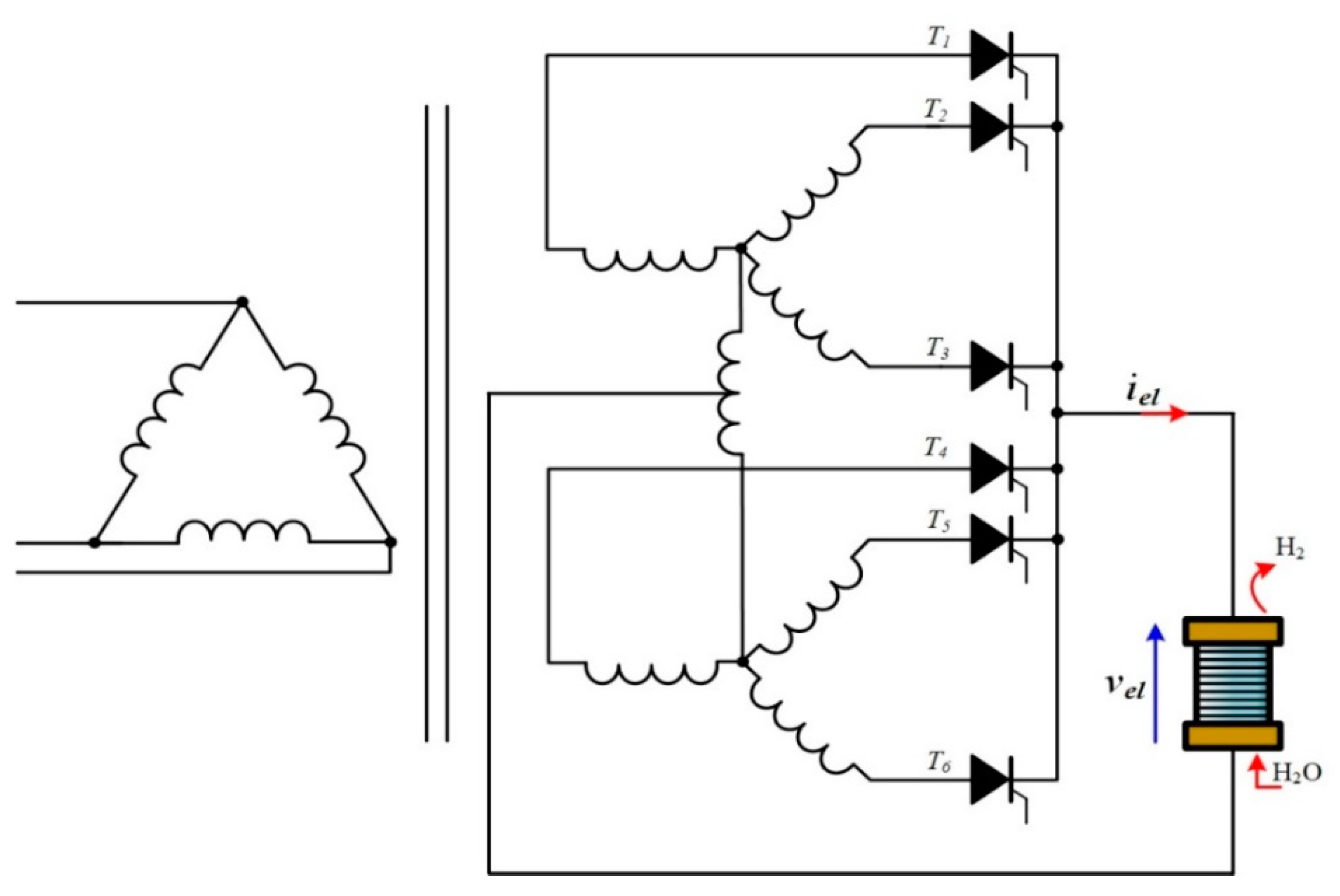
4.2.4. 12-Pulse Thyristor Double-Star Rectifier with Inter-Phase Transformers
From the configuration of the six-pulse thyristor double-star rectifier, two can be connected in parallel to obtain a 12-pulse diode double-star rectifier as shown in
Figure 11 [
13]. The four thyristor-based rectifiers are shifted by 90°, and their secondary neutral nodes are connected by using two inter-phase transformers. An additional inter-phase transformer enables interconnecting the two inter-phase transformers and the negative polarity of the electrolyzer [
54].
This configuration features a lower thyristor average and
RMS current (i.e., 50% lower [
54]) over the six-pulse thyristor double-star rectifier. Due to the phase shift of 90° between the four thyristor-based rectifiers, the output current ripple is very small, enabling optimizing the specific energy consumption and gas quality. Finally, reactive power can be compensated, improving power quality.
4.3. AC-DC Converters: Rectifier-Chopper
After introducing different types of thyristor-based rectifiers and the solutions to enhance the power quality and to reduce output current ripple, AC-DC converters based on the combination of a diode-based rectifier and a DC chopper have much to offer. Indeed, this combination allows for improving the power factor without using bulky low harmonics passive filters and other solutions; making it more cost-effective. Generally, it includes a six-pulse diode bridge rectifier (
Figure 4) providing a DC voltage to supply a classic step-down DC-DC converter (i.e., buck). The current control is realized through the step-down converter to manage the hydrogen flow rate and energy efficiency of the electrolyzer. In the next subsection, different combinations of rectifier-chopper are introduced and discussed in terms of power quality, cost, energy efficiency, reliability, and current ripple. The following circuits allow switching frequency much higher the line frequency; for this reason, reactive elements have smaller values and in general, the dynamic of the converter is faster. With a suitable control circuit, both feedback on the output voltage and current can be achieved. In general, such converters show a closed-loop dynamic response faster than the source (considering a RES) the electrolyzer. On the other hand, the dynamics of the electrolyzers in general influence the small-signal transfer function of the converter, and consequently, the stability.
4.3.1. Six-Pulse Diode Bridge Rectifier with a Buck Converter
The following converters operate based on fixed voltage DC bus and a high-frequency switching conversion stage. The input transformer can be adopted depending on the power and grid distribution (LV or mV). The residual ripple of the DC bus on the output voltage can be eliminated by a suitable choice of the control system of the switching conversion stage. In
Figure 12, the classic combination of a six-pulse diode bridge rectifier connected to a step-down DC-DC converter is shown. To convert the AC voltage into a DC voltage, a six-pulse diode bridge rectifier is used, allowing for providing an average DC voltage according to the voltage specification of the AC power supply (i.e., power grid, wind turbine). This average DC voltage is given by Equation (7). Since the three-phase diode bridge rectifier cannot be controlled due to the use of diodes, a step-down DC-DC converter has to be employed to control the current through the single power switch (i.e., IGBT) from the hydrogen flow rate and energy efficiency points of view. Since a step-down DC-DC converter includes a few components, its cost is reduced.
The output voltage of the step-down converter neglecting the parasitic elements is expressed by [
54]:
where
D is the duty cycle of the power switch
S1, (defined as the ratio of its conduction time and the switching period), included between 0 and 1; whereas
VDC is the output DC voltage of the rectifier. The capacitor
CDC allows smoothing the voltage ripple.
The output current ripple Δ
iel is given by [
54]:
where
L1 is the inductor in (H) and
fs is the switching frequency in (Hz) of the converter. From Equation (13), it can be noted that the higher the inductor and the switching frequency, the lower the current ripple. Low current ripple is one of the most important features for electrolyzers in optimizing their specific energy consumption and reliability [
20,
21]. On one hand, when increasing the inductor values, it leads to a higher cost and volume. It can be noted that the whole current
iel flows through the inductor, which is a design limit for high-current electrolyzers. A low value of L can be adopted for increasing the switching frequency. On the other hand, the higher the switching frequency, the higher the switching losses [
54]. For this reason, a compromise has to be found to optimize energy efficiency while reducing the current ripple [
13]. Different solutions have been proposed to decrease the switching losses such as the use of soft-switching techniques and wide-bandgap semiconductors (GaN, SiC)) [
19,
57].
Since a step-down DC-DC converter allows for decreasing the voltage, high currents can be obtained by optimizing energy efficiency. This topology suffers from having high voltage stress for high-power applications. Furthermore, the power level is limited due to the use of a single power switch. From the reliability point of view, the converter is no fault-tolerant in case of power switch failures.
Another important feature offered by this topology is the fast-current dynamic response due to the high-switching frequency (i.e., >20 kHz) compared to the usual frequency for thyristor-based rectifiers (around few kHz). From the power quality point of view, a high value of the capacitor
CDC needed to minimize the ripple due to the rectifier implies a pulse-shaped current. The generation of reactive power can be reduced while improving the power factor [
21]. To further enhance the power factor, passive filters can be used at the power supply side.
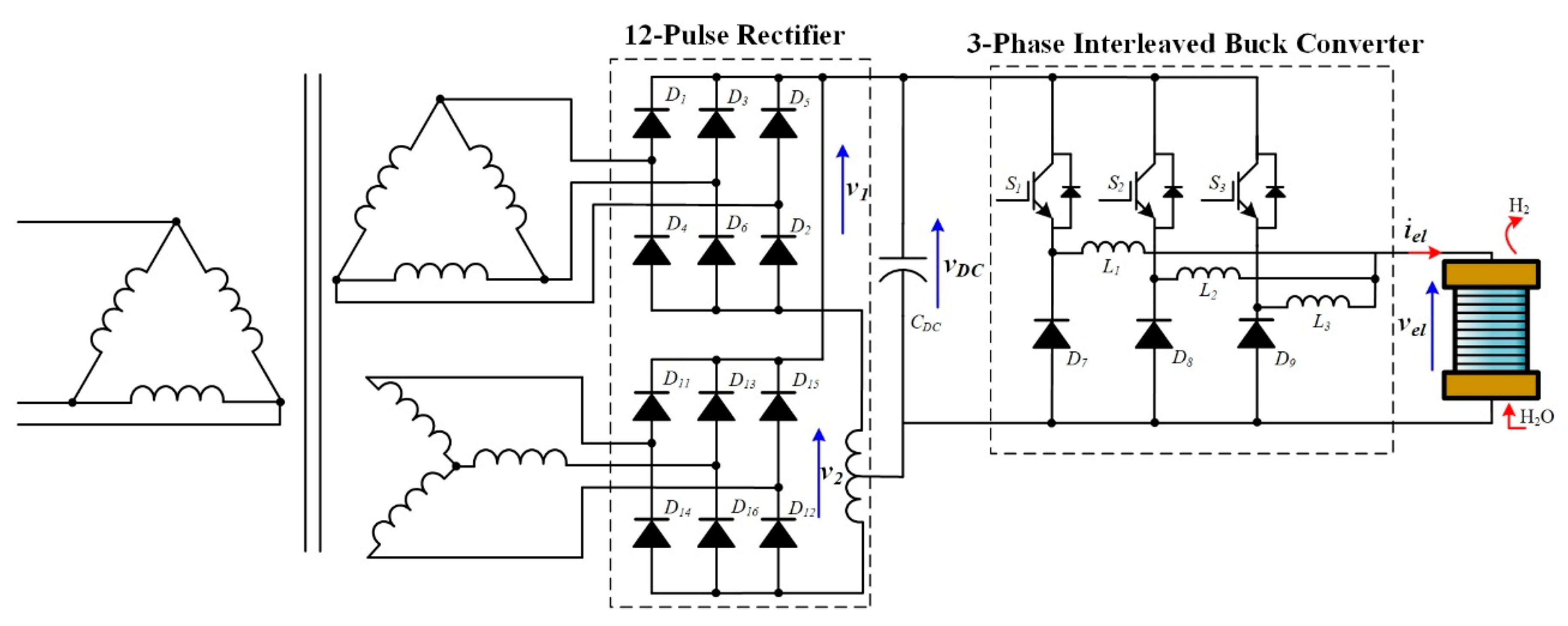
4.3.2. Six-Pulse or 12-Pulse Diode Bridge Rectifier with a Three-Phase Interleaved Buck Converter
To decrease the output current ripple, a six-pulse diode bridge rectifier connected to a three-phase interleaved buck converter is shown in
Figure 13. The choice of three phases results in a compromise between the output current ripple and volume reduction, energy efficiency, and reliability in case of power switch failures. The efficiency improvement is mainly due to the share of the current
iel among many inductors since Joule losses into the parasitic resistance depend on the square of the current.
Each power switch (i.e.,
S1,
S2, and
S3) is controlled with a phase shift angle of 120°, reducing the output current ripple and volume of inductors. The output voltage
Vel is given by Equation (12). According to the duty cycle value, the output current ripple is expressed by the following expressions [
2]:
From Equations (14)–(16), it can be noted that the output current ripple is canceled for specific duty cycles (i.e., 1/3 and 2/3). Furthermore, compared to a classic step-down DC-DC converter, a three-phase interleaved buck converter can continue to supply the electrolyzer without any interruption in case of power switch failures due to its static redundancy. However, it leads to additional current stresses and a higher current ripple due to a no suitable phase shift angle. To overcome this issue, the phase shift angle has to be modified in 180° to operate the converter as a two-phase interleaved buck converter [
58]. Even though this topology suffers from having a limited conversion gain and high voltage stress, it is particularly for high-power applications due to the share of the input current between the phases [
59]. The energy efficiency can be improved compared to a classic step-down converter, but the losses are particularly important at low-input DC voltage due to the high duty cycle value. The higher the duty cycle, the lower the energy efficiency. Since this topology requires additional elements, the cost is generally higher than a classic step-down converter even in this last case if the availability and the cost of a single inductor can orient the designer towards the interleaved topology.
Finally, a three-phase interleaved buck converter offers the same benefits from the power quality point of view. For high-current applications, the six-pulse rectifier can be substituted by a 12-pulse diode bridge rectifier (as shown in
Figure 14), but leads to additional cost and volume.
4.3.3. Six-Pulse Diode Bridge Rectifier with a Two-Phase Stacked Interleaved Buck Converter
Another interesting configuration consists of coupling a six-pulse diode bridge rectifier with a two-phase stacked interleaved buck converter (SIBC) as shown in
Figure 15. It was first introduced in [
16,
18] to control the electrolyzer according to the available power from a wind turbine conversion system.
The diodes in
Figure 13 are replaced by IGBT to reduce the conduction losses since the on-state resistances of IGBT are smaller than diodes; for low-power applications, MOSFET can also be adopted [
60]. Furthermore, an additional capacitor
Cs is used between the first and second phase to block the DC component of the current flowing through the second phase (i.e., s). As a result, only the AC component of the current flows through the second phase. The couple of IGBTs (i.e.,
S1,
S4, and
S2,
S3) are controlled in an opposite way (instead of 180° for a two-phase interleaved buck converter). Hence, both AC components of the current flowing through the first and second phases can be canceled. Only a pure DC current flows through the electrolyzer, regardless of the operating condition, optimizing its reliability and energy efficiency [
18].
From the reliability point of view, the SIBC can continue to operate even in case of power switch failures. However, the current ripple is higher in this case and given by Equation (13). The SIBC suffers from the same drawbacks compared to a three-leg interleaved buck converter, particularly the losses at low input DC voltage.
Finally, a good power factor can be assured; as it concerns the power quality from the AC power supply, it is influenced by the pulse shaped current. It is the future challenge whose pathway passes through new active rectifiers topologies.
5. Discussion and Future Challenges
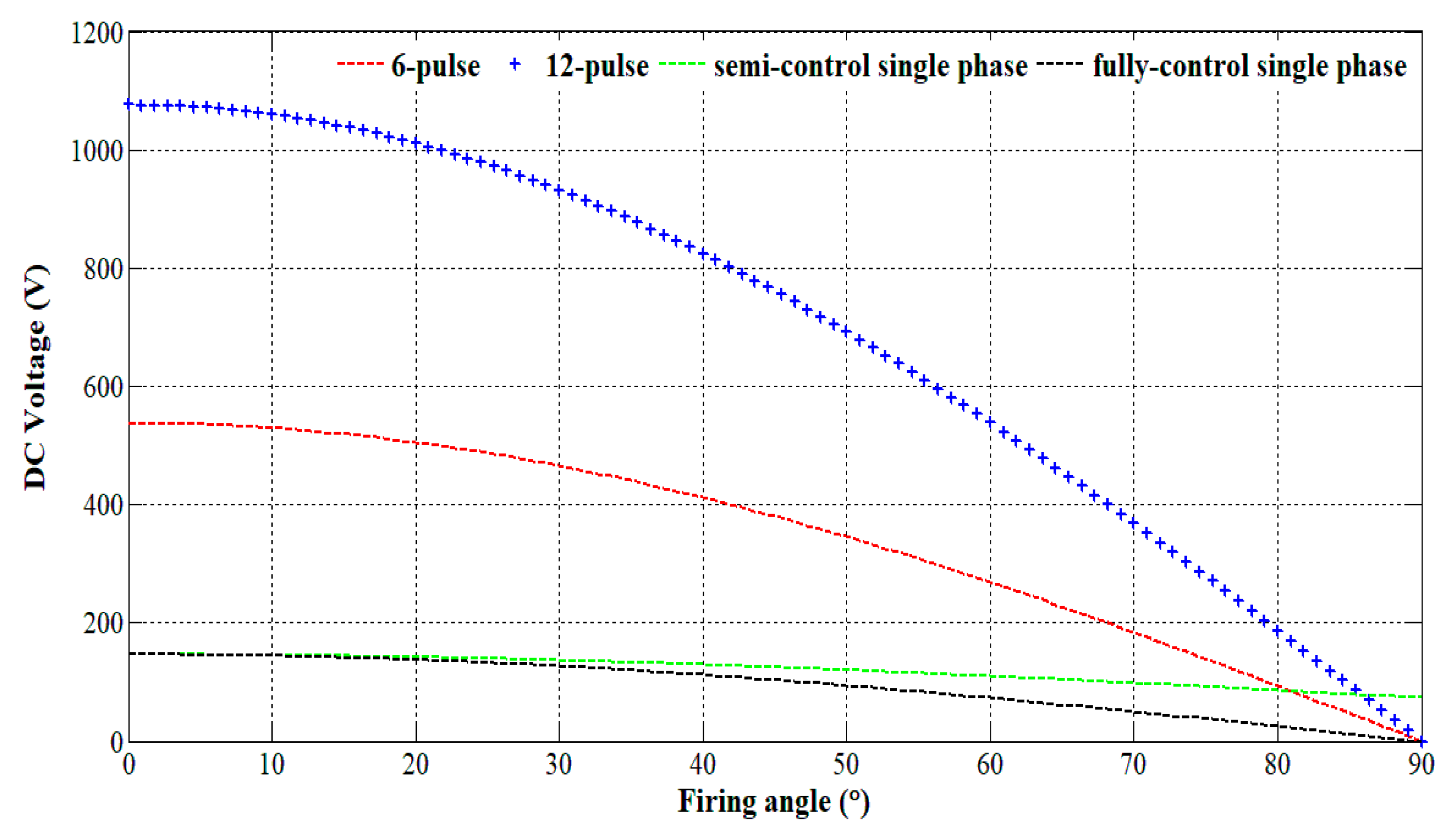
Currently, AC-DC converters based on thyristor or diode rectifier-DC chopper are mainly used to supply alkaline and PEM electrolyzers. For high-current applications, particularly met for alkaline electrolyzers, thyristor-based rectifiers dominate the market including industrial and power-to-gas applications. Despite the fact that these rectifiers are mature technologies offering high energy efficiency, reliability, and good control of the current, they suffer from degrading the power quality from the AC side by injecting reactive power and having high current ripple. The generation of reactive power is due to the firing angle to control the thyristor. In comparison, high current ripple increase the losses in the electrolyzer, and consequently the specific energy consumption. The 12-pulse thyristor based-rectifier allows for increasing the output voltage and the current due to the series or parallel connection of two six-pulse thyristor based-rectifiers. Although it can enhance the power quality and reduce the output current ripple, the volume and cost remain major concerns. To improve the power quality and decrease output current ripple, passive filters and active filters based on STATCOM and DSTATCOM can be employed. However, these solutions increase the complexity of the system, cost, and volume.
To choose the most suitable topology based on the electrical requirements of the electrolyzer, a comparison of the output DC voltage according to the firing angle is shown in
Figure 16. It is calculated considering a unitary transformer ratio supplied by the low-voltage main.
In
Figure 16, six-pulse (
Figure 8), 12-pulse (
Figure 9) thyristor-based rectifiers, and single-phase semi-controlled (thyristors, diodes) and fully controlled (thyristors) rectifiers have been considered. It has to be noted that 12-pulse thyristor-based rectifiers are particularly fit for high-voltage and high-current applications; whereas six-pulse thyristor-based rectifiers are more suitable for medium-power applications. Concerning single-phase thyristor-based rectifiers, they have to be considered for low-power applications.
To cope with the use of active and passive filters to enhance the power quality and to reduce output current ripple, the combination of a six-pulse diode rectifier connected to a DC chopper is an interesting alternative. Indeed, it enables improving the power quality by decreasing the input current harmonic content. Furthermore, through the step-down DC-DC converter, the electrolyzer current can be controlled offering better dynamic responses, particularly suitable when the electrolyzer is coupled to a wind turbine conversion system. By considering a six-pulse diode bridge rectifier, with the DC output voltage being lower than 600 V (
Figure 16), low- and medium-power applications are considered since the step-down DC-DC converter enables decreasing this output voltage to supply the electrolyzer. However, a small difference between the input and the output voltage of the step-down DC-DC converter leads to more losses and consequent reductions in the energy efficiency due to the high duty cycle operation. Furthermore, classic step-down DC-DC converters are not reliable in case of power switch failures and generate higher current ripple for a small inductor. To face both issues, interleaved buck converters can be employed, enhancing the availability of the converter in case of electrical failures and decreasing the output current ripple. Over the classic interleaved buck converter, a stacked interleaved buck converter can cancel the output current ripple for any operating condition. However, the use of these topologies is limited by their step-down ratio and high voltage stress.
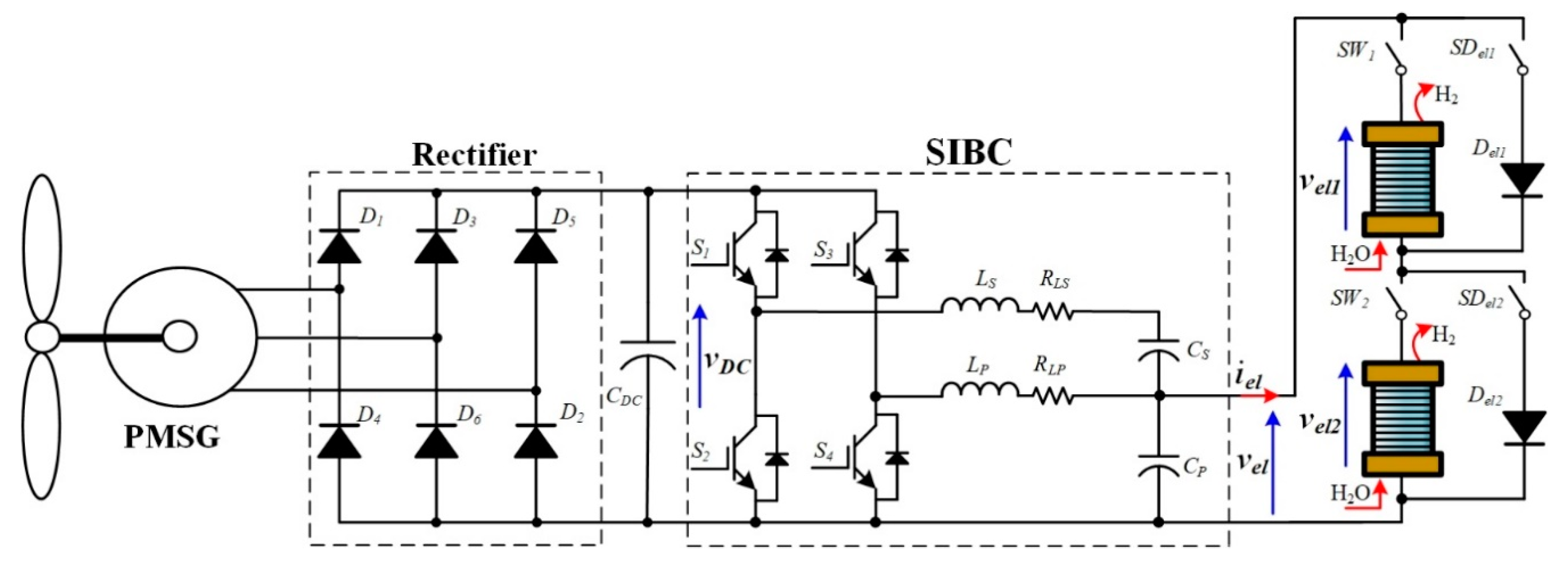
To meet these issues, in [
61], a three-level interleaved DC-DC buck converter can be used, interfacing a wind energy conversion system and an electrolyzer (
Figure 17). Indeed, the voltage stress on the power electronics devices can be reduced while keeping low output current ripple, enhancing step-down ratio, reliability, and high energy efficiency. When coupling wind energy conversion systems with electrolyzers, multi-stack architectures have much to offer, particularly from the energy management point of view [
16]. Two different configurations can be employed such as series architecture (
Figure 18) and parallel architecture (
Figure 19) [
62]. In
Figure 18, according to the available power from the wind turbine, the power can be shared between the electrolyzers through the use of switches (i.e.,
SW1,
SW2,
SDel1, and
SDel2) and bypass diodes (i.e.,
Del1 and
Del2). Furthermore, the switches (i.e.,
SW1,
SW2) can be used to isolate a faulty electrolyzer stack; whereas the switches (i.e.,
SDel1, and
SDel2) are employed to deviate the path of the electrolyzer current if one of the stacks is faulty. The diodes have to be chosen to withstand the electrolyzer current to avoid their destruction. Hence, the bypass diode can ensure the continuity of service of the multi-stack system. However, the simplicity of architecture leads to weaknesses.
Indeed, the electrolyzers cannot be controlled separately and the energy efficiency of the electrolyzer is lower due to the increase of the output voltage. On the other side, by choosing another DC-DC converter topology such as the three-level interleaved buck converter (
Figure 17), the increase of the output voltage leads to better energy efficiency due to its low step-down voltage conversion. In comparison, the parallel configuration enables controlling each electrolyzer stack through the DC-DC converter connected to the DC bus. In this case, the energy efficiency of the DC-DC converters is optimized due to lower duty cycles. However, this architecture is more expensive due to the use of several DC-DC converters [
62]. Based on the available power, the DC-DC converters are controlled to supply the electrolyzer at rated power to optimize both energy efficiency and hydrogen flow rate [
16].
All the above-mentioned topologies conceived to directly couple an electrolyzer with a permanent magnet synchronous generator (PMSG) supplied by a wind turbine adopt uncontrolled diode rectifiers are cost-efficient solutions; in any case, it can introduce low-frequency pulsation with possible mechanical shaft resonance. For this reason, active rectifiers are also becoming of interest for low-power applications [
27,
63].
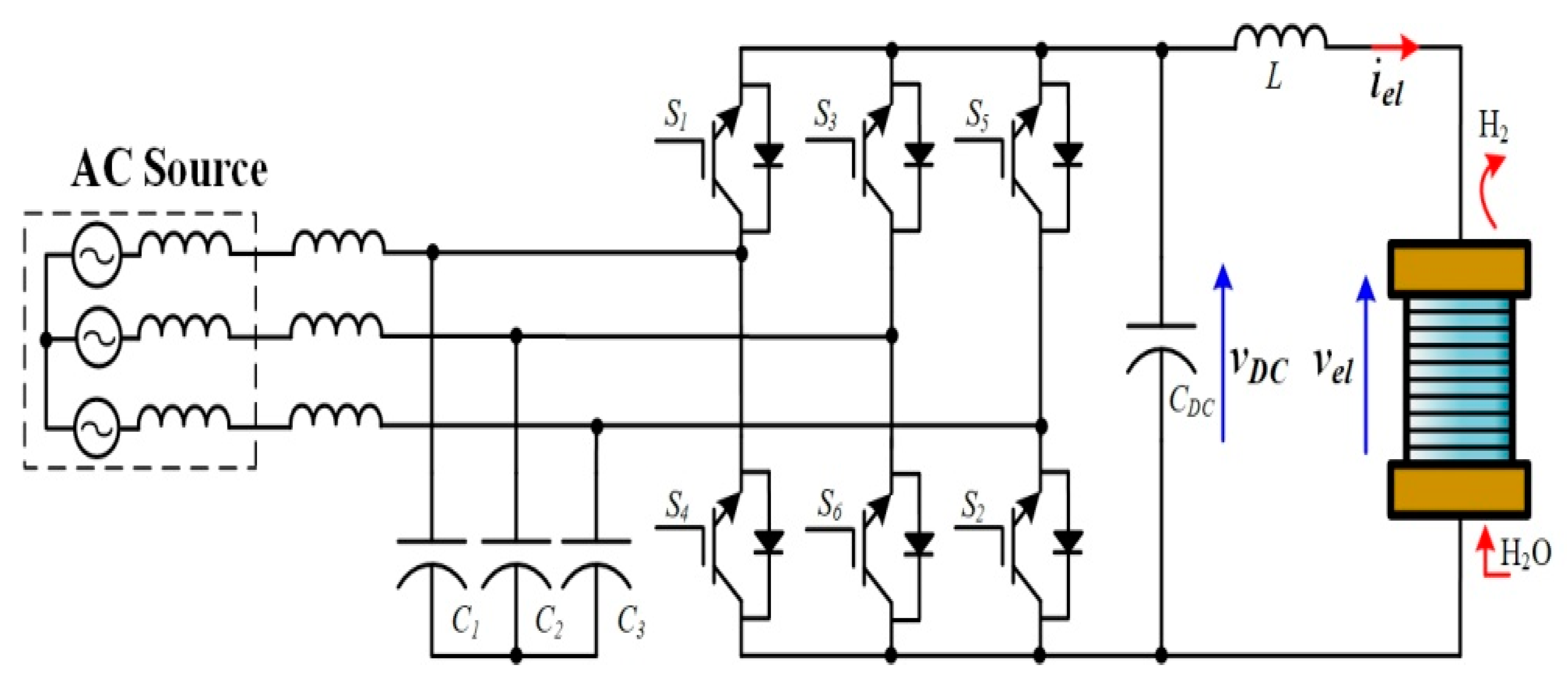
Finally, even though it has not been reported for practical use in electrolyzer applications, PWM current-source rectifiers (CSR) are attractive and promising topologies for future applications as shown in
Figure 20. Indeed, they offer good control of the output current, and excellent power factor and fast dynamics [
54,
64]. Generally, these topologies are composed of GTO devices (gate-turn-off thyristors) due to their high current and voltage ratings. However, recent advances in high-voltage and high-power applications for IGBT (i.e., insulated gate bipolar transistor) have been significant and have allowed their development in PWM-CSRs. To reduce the output current ripple, an inductor is required; whereas at the AC side, capacitors are mandatory to filter the input current ripple [
11]. However, these topologies are not suitable for high-power applications due to the high voltage and current stress, drastically increasing the conduction losses; and thus, decreasing the energy efficiency. For this reason, PWM-CSRs are fit for medium-voltage applications [
13].
This article has shown that the high-power conversion plants use alkaline electrolyzers whose supply is based on controlled rectifiers or IGBT choppers [
11,
12] these circuits are constrained by the management of high currents and are supplied by the medium voltage grid. The use of thyristor or IGBT makes these converters reliable but implies the generation of harmonics towards the grid and limited voltage regulation at the output [
17]. The limited availability of new high-power devices for these applications influences the development of new topologies together with the cost of the plants. Contrarily, in the range of power between 1 mW and 30 kW, there are many interesting new solutions. In this range, both alkaline and PEM electrolyzers can be used even if most electrolyzers near to the lower limit are PEM. New topologies such as active rectifiers [
27,
63] assure a low impact on the grid or the best exploitation of the PMSM generator for the wind turbine. The rectifiers interfaced by a DC/DC converter give a good voltage regulation minimizing the output voltage ripple. Many DC/DC converters have been proposed for these applications [
65]. They can be parallel connected exploiting modularity and increasing reliability with an appropriate control [
18]. Current-source rectifiers (CSR) can also be used due to the good control of the output current, excellent power factor, and fast dynamics [
54,
64].
In the low power range, only PEMs are available, the circuits described in the previous power range can be used as well and equipped with MOSFETs. For very low power (around 1 kW), the use of uncontrolled rectifiers together with a simple DC/DC stage allows cheap realization.
From this discussion,
Table 5 provides a summary of power electronics required according to the power range of the electrolyzer.
6. Conclusions
Water electrolysis technologies to produce hydrogen can give a relevant contribution to the lessening of CO2 pollution. Even if hydrogen is intrinsically a clean energy vector, its production requires energy, which makes the difference. Unfortunately, the hydrogen produced by fossil fuels, namely grey hydrogen, is more than 90% of the total production. A low carbon threshold is reached by blue hydrogen, meaning by nuclear; in any case, the store or minimization of the effects of radioactive waste is still a challenge. Green hydrogen produced by renewable sources such as solar or wind meets the low-carbon threshold. In this paper, the authors focused the attention on technical aspects of hydrogen production, such as the harmonic pollution when the electrolyzer is supplied by the grid, the knowledge of the dynamics of the converter and the electrolyzer in case of supply by renewable energy sources, the need of a conversion chain to fit the voltage levels, and an adequate efficiency. However, even if there are much progress from the technological point of view, these endeavors need to be accomplished by public policy decisions. Among these, there is a need to incentivize the use of hydrogen, it can be used for urban traction, but requires support from refilling points that can be obtained by investments on the distribution grid. Moreover, the power-to-gas (P2G) is attractive since this technology uses electrolysis to produce hydrogen that can be used directly, or further steps may convert it into syngas, methane, or liquefied petroleum gas (LPG).
This work aimed at introducing the main current issues with the use of AC-DC converters from the power quality, reliability, energy efficiency, cost, current control, and output current ripple points of view. Two families of AC-DC converters are generally employed to supply electrolyzers such as the thyristors-based rectifiers and rectifiers-DC choppers. Currently, thyristors-based rectifiers dominate the market for industrial and power-to-gas applications because the generation of high-currents is required to supply high-power electrolyzers. However, the use of thyristors involves the generation of reactive power, drastically reducing the power factor. Furthermore, the output current ripple is quite high, leading to an increase in the specific energy consumption. To cope with these issues, active and passive filters have to be used, but make the system more complex while increasing the cost and the volume. On the other side, the use of a 12-pulse thyristor based-rectifiers allows for obtaining higher voltage and current while enhancing the power quality. However, current ripple, cost, and volume remain major concerns.
In comparison, the combination of rectifier-DC chopper can avoid the use of bulky active and passive filters since it can enhance power quality. Based on the architecture of the step-down DC-DC converter, reliability in the case of power switch failures and output current ripple reduction can be ensured. However, it is important to employ new emerging DC-DC converters and power management strategies to improve the energy efficiency and the hydrogen flow rate, requested when coupling with wind turbine conversion system.
Finally, PWM current-source rectifiers are considered attractive topologies to meet the power quality, control of current, and dynamics response time issues. However, their use must be limited to medium-voltage applications to maintain good energy efficiency.
Future challenges are then related to the more massive use of RES and related conversion systems with new power devices allowing fast dynamics of converters and improved efficiency. The allowed higher switching frequency will lessen the size of reactive components in converters making easier filtering. The reduced whole cost of the conversion chain will make the retrofit of existing plants competitive and can encourage new realizations.

 ,
, 


