Non-Invasive Method for In-Service Induction Motor Efficiency Estimation Based on Sound Acquisition

Abstract
:Featured Application
Abstract
1. Introduction
2. Efficiency Estimation Methods
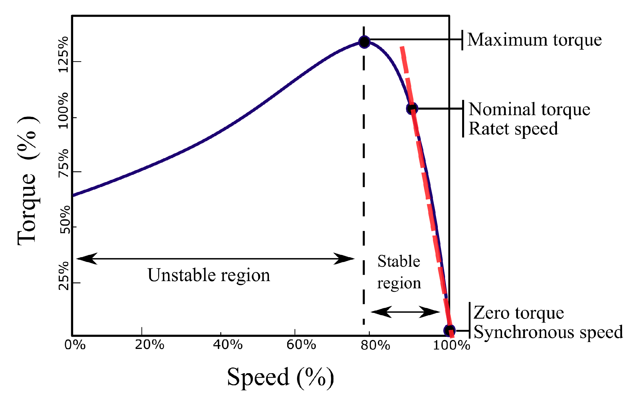
2.1. Air Gap Torque Method
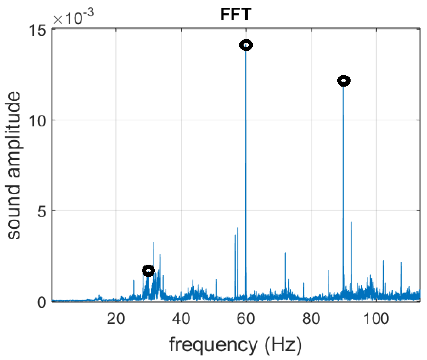
2.2. Efficiency Estimation from IM Sound Analysis
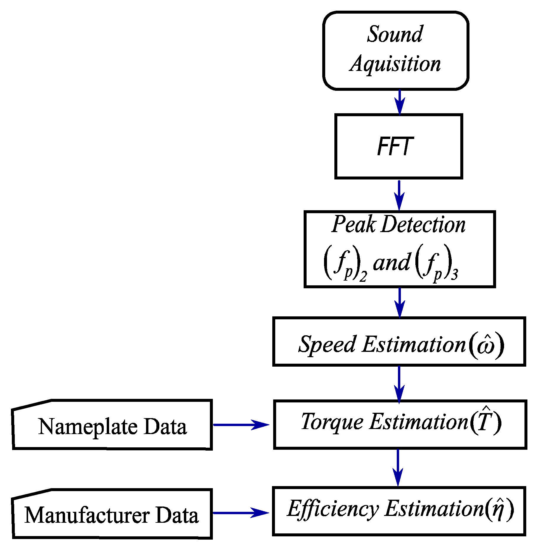
3. Methodology
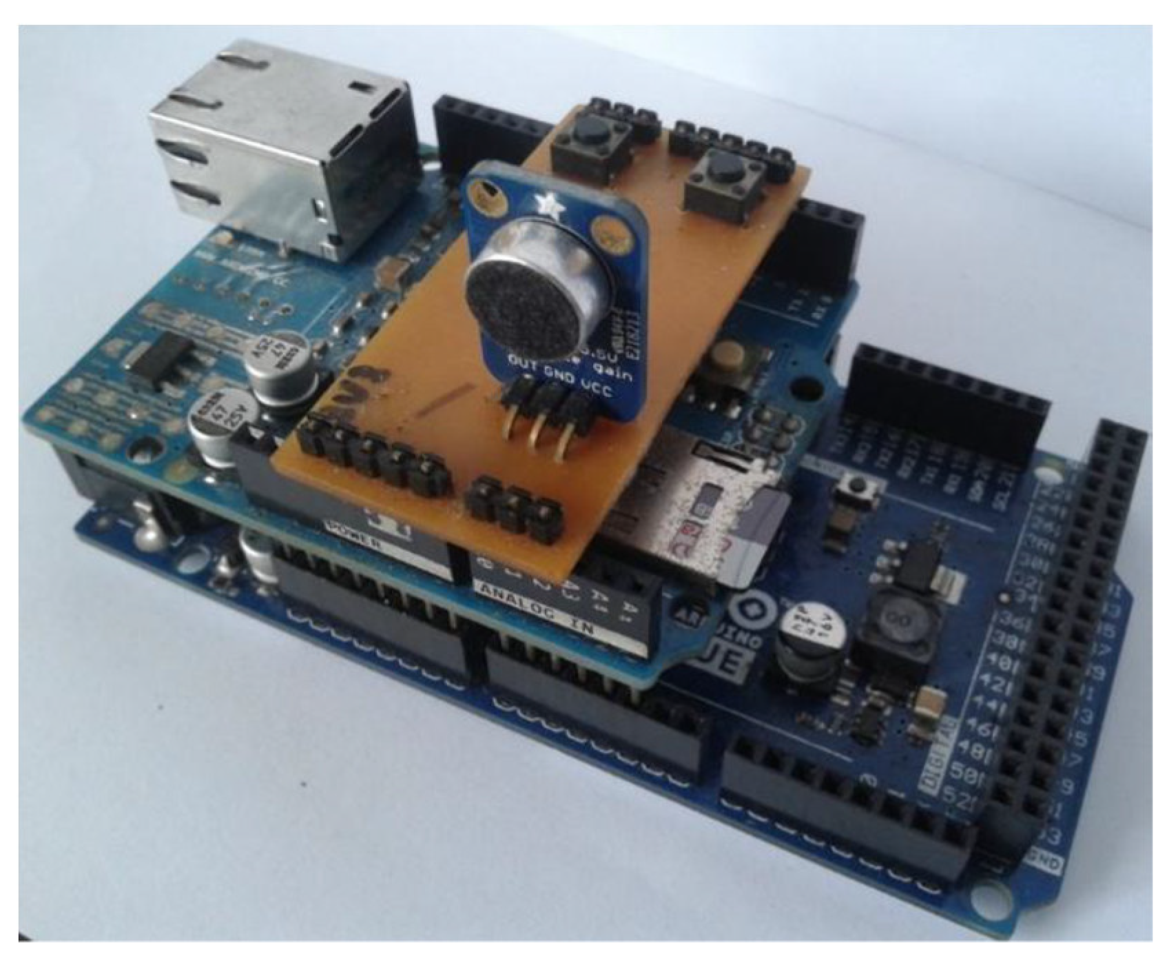
3.1. Sound Acquisition System
3.2. Method Description
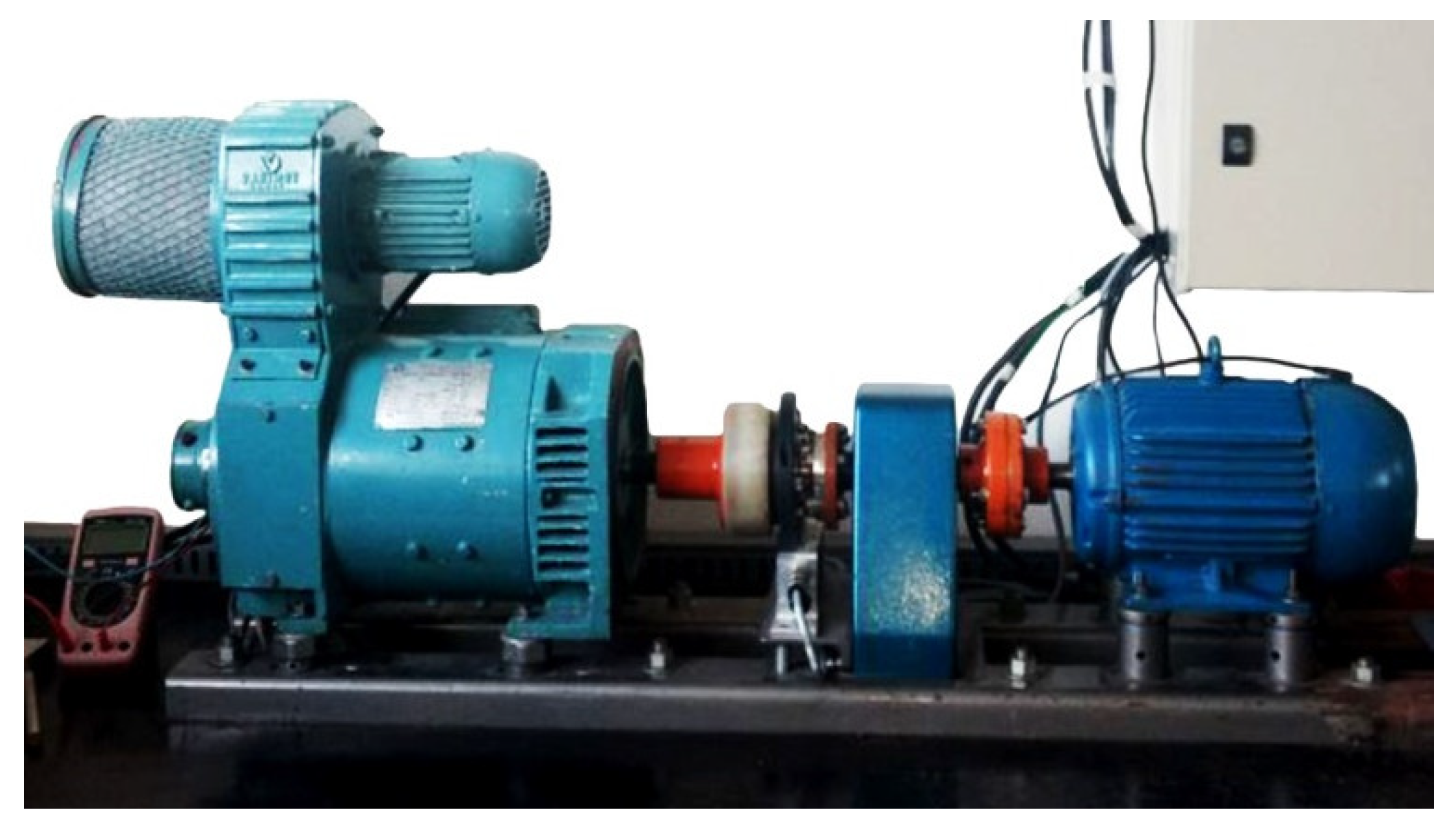
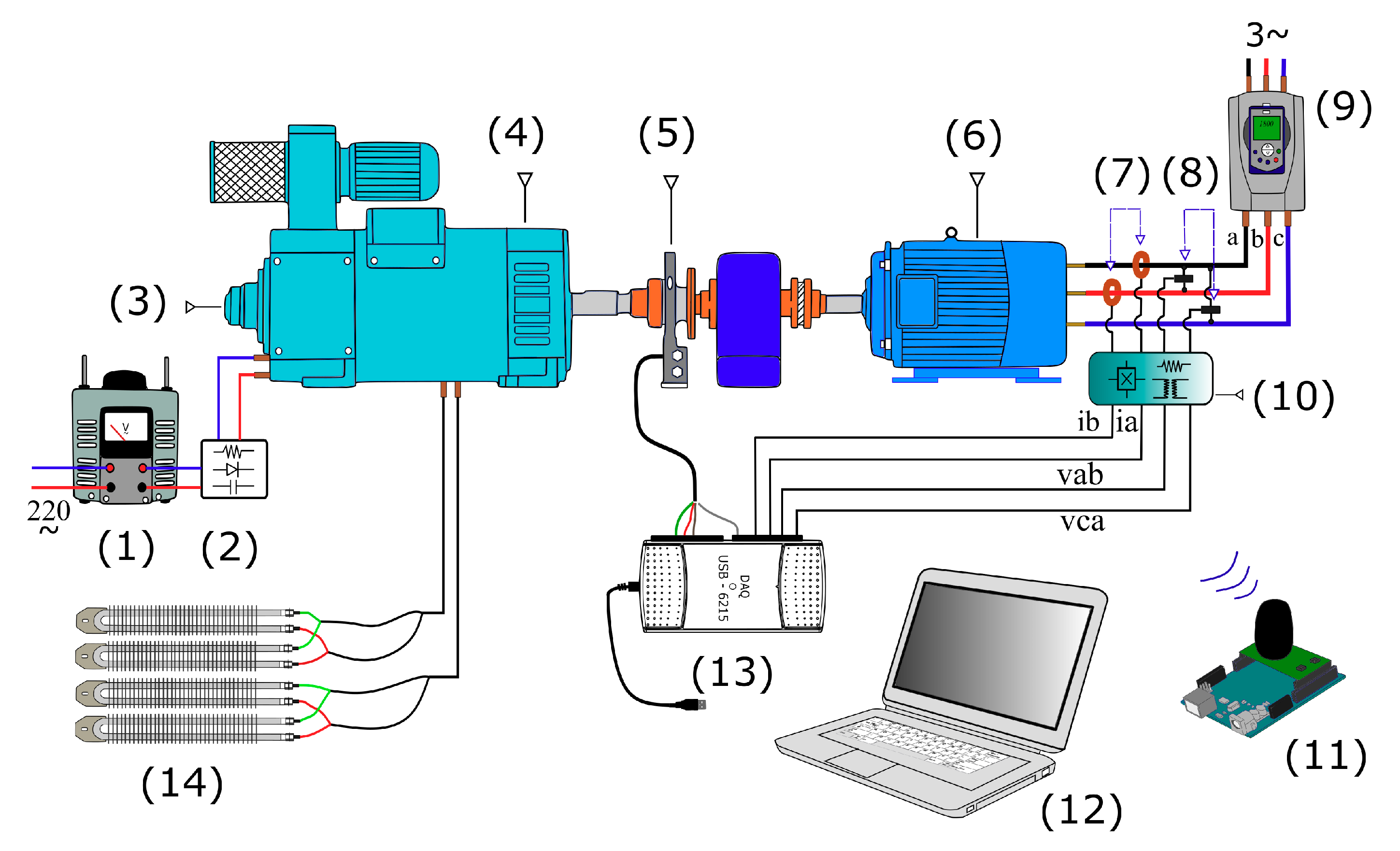
3.3. Test Workbench
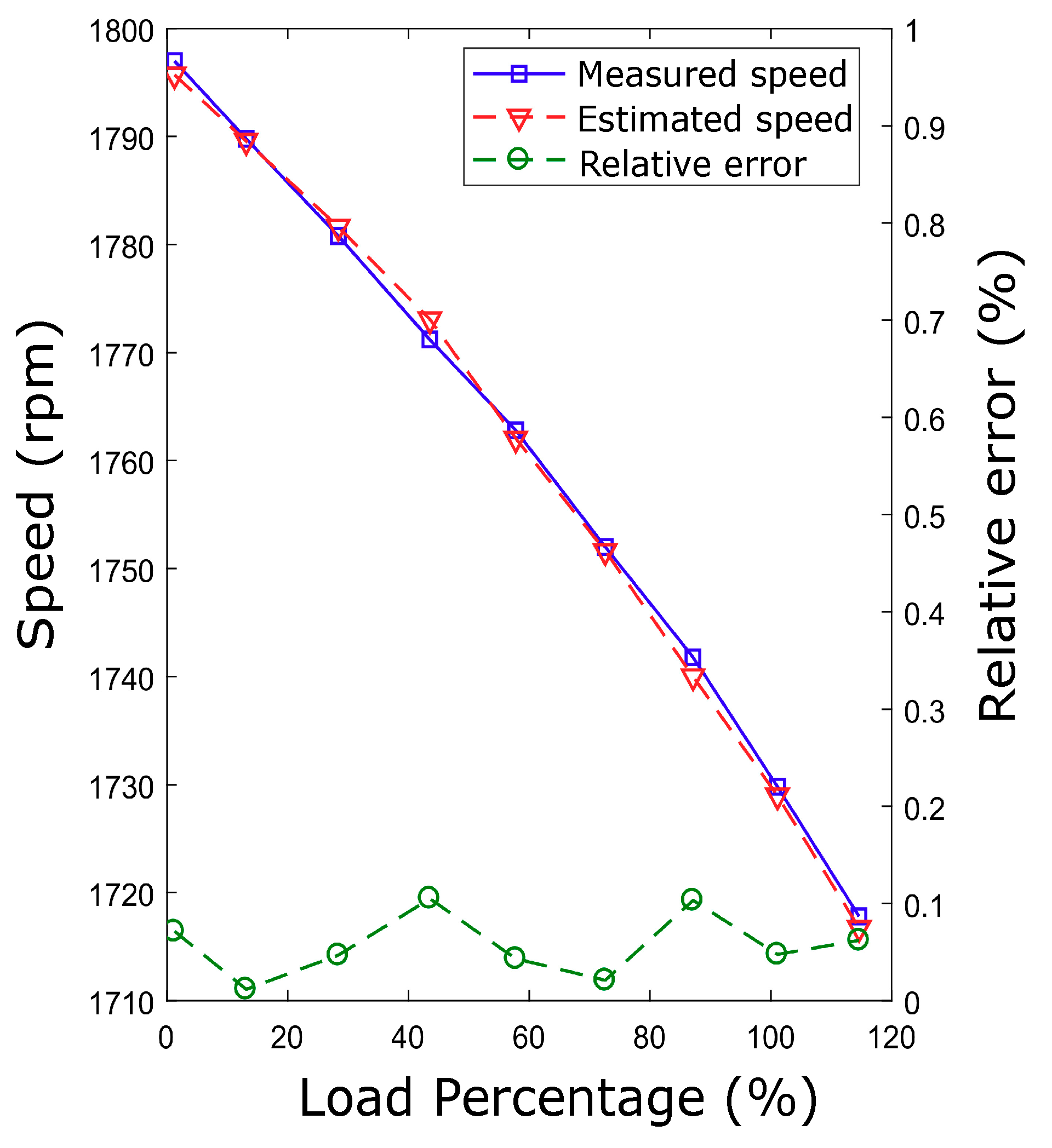
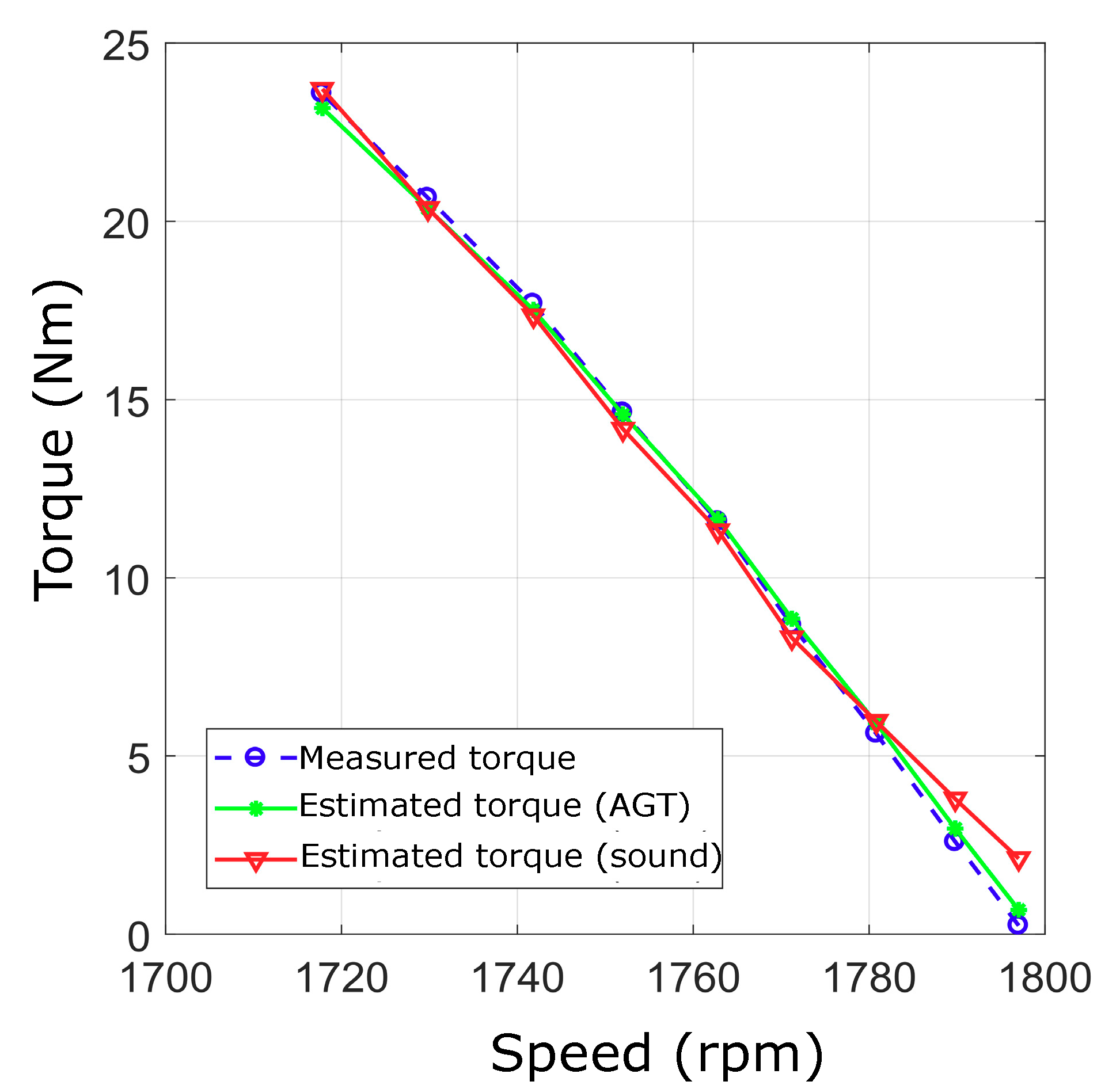
4. Results
5. Conclusion
Author Contributions
Funding
Acknowledgments
Conflicts of Interest
References
- Multifault Diagnosis of Induction Motor at Intermediate Operating Conditions Using Wavelet Packet Transform and Support Vector Machine. Available online: https://asmedigitalcollection.asme.org/dynamicsystems/article-abstract/140/8/081014/440131/Multifault-Diagnosis-of-Induction-Motor-at?redirectedFrom=fulltext (accessed on 26 April 2020).
- Beleiu, H.G.; Maier, V.; Pavel, S.G.; Birou, I.; Pică, C.S.; Dărab, P.C. Harmonics Consequences on Drive Systems with Induction Motor. Appl. Sci. 2020, 10, 1528. [Google Scholar] [CrossRef] [Green Version]
- Lu, B.; Habetler, T.G.; Harley, R.G. A survey of efficiency-estimation methods for in-service induction motors. IEEE Trans. Ind. Appl. 2006, 42, 924–933. [Google Scholar]
- Goman, V.; Oshurbekov, S.; Kazakbaev, V.; Prakht, V.; Dmitrievskii, V. Energy Efficiency Analysis of Fixed-Speed Pump Drives with Various Types of Motors. Appl. Sci. 2019, 9, 5295. [Google Scholar] [CrossRef] [Green Version]
- Implementation and Deployment of an Intelligent Industrial Wireless System for Induction Motor Monitoring. Available online: https://asmedigitalcollection.asme.org/dynamicsystems/article-abstract/139/12/124502/474466/Implementation-and-Deployment-of-an-Intelligent?redirectedFrom=fulltext (accessed on 26 April 2020).
- Younsi, M.O.; Lecointe, J.; Ninet, O.; Morganti, F.; Brudny, J.; Zidat, F. A Noninvasive External Flux Based Method for In-Service Induction Motors Torque Estimation. IEEE Trans. Energy Convers. 2019, 34, 782–788. [Google Scholar] [CrossRef]
- IEEE Power Engineering Society. IEEE Standard Test Procedure for Polyphase Induction Motors and Generators; IEEE Power Engineering Society: Piscataway, NJ, USA, 2004; Volume 112, p. 87. [Google Scholar]
- Al-Badri, M.; Pillay, P.; Angers, P. A Novel In Situ Efficiency Estimation Algorithm for Three-Phase Induction Motors Operating With Distorted Unbalanced Voltages. IEEE Trans. Ind. Appl. 2017, 53, 5338–5347. [Google Scholar] [CrossRef]
- Zhang, H.; Zanchetta, P.; Bradley, K.J.; Gerada, C. A Low-Intrusion Load and Efficiency Evaluation Method for In-Service Motors Using Vibration Tests With an Accelerometer. IEEE Trans. Ind. Appl. 2010, 46, 1341–1349. [Google Scholar] [CrossRef]
- Hsu, J.S.; Kueck, J.D.; Olszewski, M.; Casada, D.A.; Otaduy, P.J.; Tolbert, L.M. Comparison of induction motor field efficiency evaluation methods. IEEE Trans. Ind. Appl. 1998, 34, 117–125. [Google Scholar] [CrossRef] [Green Version]
- Lu, B.; Habetler, T.G.; Harley, R.G. A Nonintrusive and In-Service Motor-Efficiency Estimation Method Using Air-Gap Torque With Considerations of Condition Monitorin. IEEE Trans. Ind. Appl. 2008, 44, 1666–1674. [Google Scholar] [CrossRef]
- Lima Filho, A.C.; Gomes, R.D.; Adissi, M.O.; Silva, T.A.B.; Belo, F.A.; Spohn, M.A. Embedded System Integrated Into a Wireless Sensor Network for Online Dynamic Torque and Efficiency Monitoring in Induction Motors. IEEE/ASME Trans. Mechatron. 2012, 17, 404–414. [Google Scholar] [CrossRef]
- Salomon, C.P.; Sant’Ana, W.C.; da Silva, L.E.B.; Lambert-Torres, G.; Bonaldi, E.L.; de Oliveira, L.E.; da Silva, J.G.B. Induction Motor Efficiency Evaluation Using a New Concept of Stator Resistance. IEEE Trans. Instrum. Meas. 2015, 64, 2908–2917. [Google Scholar] [CrossRef]
- Santos, V.S.; Felipe, P.R.V.; Sarduy, J.R.G.; Lemozy, N.A.; Jurado, A.; Quispe, E.C. “Procedure for Determining Induction Motor Efficiency Working Under Distorted Grid Voltages”. Trans. Energy Convers. 2015, 30, 331–339. [Google Scholar] [CrossRef]
- Sakthivel, V.P.; Bhuvaneswari, R.; Subramanian, S. Non-intrusive efficiency estimation method for energy auditing and management of in-service induction motor using bacterial foraging algorithm. IET Electr. Power Appl. 2010, 4, 579–590. [Google Scholar] [CrossRef]
- Siraki, A.G.; Pillay, P. An In Situ Efficiency Estimation Technique for Induction Machines Working With Unbalanced Supplies. IEEE Trans. Energy Convers. 2012, 27, 85–95. [Google Scholar] [CrossRef]
- Madahana, M.; Nyandoro, O.; Moroe, N. Engineering noise control for mines: Lessons from the world. S. Afr. J. Commun. Disord. 2020, 67, 5. [Google Scholar] [CrossRef] [PubMed]
- Wang, Y.S.; Ma, Q.H.; Zhu, Q.; Liu, X.T.; Zhao, L.H. An Intelligent Approach for Engine Fault Diagnosis Based on Hilbert-Huang Transform and Support Vector Machine. Appl. Acoust. 2014, 75, 1–9. [Google Scholar] [CrossRef]
- Wong, P.K.; Zhong, J.; Yang, Z.; Vong, C.M. Sparse Bayesian Extreme Learning Committee Machine for Engine Simultaneous Fault Diagnosis. Neurocomputing 2016, 174, 331–343. [Google Scholar] [CrossRef]
- Glowacz, A. Fault diagnosis of single-phase induction motor based on acoustic signals. Mech. Syst. Signal Process. 2019, 117, 65–80. [Google Scholar] [CrossRef]
- Veras, F.C.; Lima, T.L.V.; Souza, J.S.; Ramos, J.G.G.S.; Lima-Filho, A.C.; Brito, A.V. Eccentricity Failure Detection of Brushless DC Motors From Sound Signals Based on Density of Maxima. IEEE Access 2019, 7, 150318–150326. [Google Scholar] [CrossRef]
- Singh, A.; Parey, A. Gearbox fault diagnosis under non-stationary conditions with independent angular re-sampling technique applied to vibration and sound emission signals. Appl. Acoust. 2019, 144, 11–22. [Google Scholar] [CrossRef]
- Feng, Z.; Zuo, M.J. Vibration signal models for fault diagnosis of planetary gearboxes. J. Sound Vib. 2012, 331, 4919–4939. [Google Scholar] [CrossRef]
- Delgado-Arredondo, P.A.; Morinigo-Sotelo, D.; Osornio-Rios, R.A.; Avina-Cervantes, J.G.; Rostro-Gonzalez, H.; Romero-Troncoso, R.J. Methodology for fault detection in induction motors via sound and vibration signals. Mech. Syst. Signal Process. 2017, 83, 568–589. [Google Scholar] [CrossRef]
- Wang, J.; He, Q. Wavelet Packet Envelope Manifold for Fault Diagnosis of Rolling Element Bearings. IEEE Trans. Instrum. Meas. 2016, 65, 2515–2526. [Google Scholar] [CrossRef]
- Garcia-Perez, A.; Romero-Troncoso, R.J.; Cabal-Yepez, E.; Osornio-Rios, R.A.; Lucio-Martinez, J.A. Application of high-resolution spectral analysis for identifying faults in induction motors by means of sound. J. Vib. Control 2012, 18, 1585–1594. [Google Scholar] [CrossRef]
- Lee, S.-B.; Habetler, T.G.; Harley, R.G.; Gritter, D.J. An evaluation of model-based stator resistance estimation for induction motor stator winding temperature monitoring. IEEE Trans. Energy Convers. 2002, 17, 7–15. [Google Scholar] [CrossRef]


© 2020 by the authors. Licensee MDPI, Basel, Switzerland. This article is an open access article distributed under the terms and conditions of the Creative Commons Attribution (CC BY) license (http://creativecommons.org/licenses/by/4.0/).
Share and Cite
César da Silva, J.; Leite de Vasconcelos Lima, T.; de Lucena Júnior, J.A.; Jordão Lyra, G.; Vidal Souto, F.; de Souza Pimentel, H.; Antônio Belo, F.; Cavalcante Lima Filho, A. Non-Invasive Method for In-Service Induction Motor Efficiency Estimation Based on Sound Acquisition. Appl. Sci. 2020, 10, 3757. https://doi.org/10.3390/app10113757
César da Silva J, Leite de Vasconcelos Lima T, de Lucena Júnior JA, Jordão Lyra G, Vidal Souto F, de Souza Pimentel H, Antônio Belo F, Cavalcante Lima Filho A. Non-Invasive Method for In-Service Induction Motor Efficiency Estimation Based on Sound Acquisition. Applied Sciences. 2020; 10(11):3757. https://doi.org/10.3390/app10113757
Chicago/Turabian StyleCésar da Silva, Júlio, Thyago Leite de Vasconcelos Lima, José Anselmo de Lucena Júnior, Gabriela Jordão Lyra, Filipe Vidal Souto, Hugo de Souza Pimentel, Francisco Antônio Belo, and Abel Cavalcante Lima Filho. 2020. "Non-Invasive Method for In-Service Induction Motor Efficiency Estimation Based on Sound Acquisition" Applied Sciences 10, no. 11: 3757. https://doi.org/10.3390/app10113757