Article

Numerical Simulation of Cross-Flow Vortex-Induced Vibration of Hexagonal Cylinders with Face and Corner Orientations at Low Reynolds Number

Griffith School of Engineering and Built Environment, Griffith University, Southport, QLD 4222, Australia
*
Author to whom correspondence should be addressed.
J. Mar. Sci. Eng. 2020, 8(6), 387; https://doi.org/10.3390/jmse8060387
Submission received: 6 April 2020 / Revised: 21 May 2020 / Accepted: 25 May 2020 / Published: 28 May 2020
(This article belongs to the Section Ocean Engineering)

Abstract

:
Vortex-induced vibrations (VIV) of hexagonal cylinders at Reynolds number of 1000 and mass ratio of 2 are studied numerically. In the numerical model, the Navier–Stokes equations are solved using finite volume method, and the fluid-structure interaction (FSI) is modelled using Arbitrary Lagrangian Eulerian (ALE) Scheme. The numerical model accounts for the cross-flow vibration of the cylinders, and is validated against published experimental and numerical results. In order to account for different angles of attack, the hexagonal cylinders are studied in the corner and face orientations. The results are compared with the published results of circular and square cylinders. Current results show that within the studied range of reduced velocities (up to 20), unlike circular and square cylinders, no lock-in response is observed in the hexagonal cylinders. The maximum normalized VIV amplitudes of the hexagonal cylinders are 0.45, and are significantly lower than those of circular and square cylinders. Vortex shedding regimes of the corner-oriented hexagons are mostly irregular. However, in the face-oriented hexagons, the shedding modes are more similar to the typical P + S and 2P modes.

1. Introduction

Vortex-induced vibration (VIV) is a major concern in design of slender structures exposed to the wind flow, such as: high-rise buildings [1,2] and bridges [3,4,5], or subject to water currents, such as: offshore platforms [6,7] marine risers [8,9,10] mooring elements [11,12,13], free spanning pipelines [14,15,16], or under action of other types of flow such as: heat exchanger tubes [17,18,19] and reactors [20,21]. As the flow passes around the bluff body, vortices are created in the wake region. These vortices generate pressure fluctuations because of a phenomenon known as “vortex shedding” that can cause bluff bodies to vibrate [22]. Vibrations may lead to fatigue damage in structures that are exposed to dynamic loads or flow-induced instabilities [23]. In the case of vortex-induced vibration, vibrations can be in two dimensions because of time-dependent drag and lift forces, as the vortices are shed from the bluff body [24].
Two fundamental experimental studies on cross-flow VIV of circular cylinders with one degree of freedom (1-DOF) were conducted by Feng [25] and Khalak and Williamson [26]. These pioneering studies showed that the VIV response is significantly related to the mass ratio, m* and the reduced velocity Vr. Mass ratio is defined as m* = m/md (the structural mass m divided by the displaced fluid mass md). The reduced velocity is defined as Vr = U/fnD, where U is the upstream velocity, D is the cylinder diameter, and fn is the natural frequency of the structure (in air or in the water). Feng’s [25] study was conducted at very high mass ratio (m* = 248) and showed two branches of response, namely, the initial and the lower branch. In the works done by Williamson et al. [26,27,28] and at low mass ratios (m* < 10), in addition to the previously reported branches, an upper branch was observed. These experimental studies showed that the vortex patterns in the initial branch comprised of “2S” modes (two single vortices in one pair per vibration cycle), while those of upper and lower branches were “2P” (two vortex pairs are shed in each cycle). Moreover, it was understood that in 1-DOF, the amplitude of response in the upper branch gets as large as the diameter of the cylinder. It was shown that in the upper and lower branches the VIV frequency coincides with the vibration frequency of the cylinder, a phenomenon known as “lock-in.” Limited research conducted on 2-DOF flow-induced vibration of circular cylinders [29,30], showed transverse vibration amplitudes of 1.5 times the diameter and 2P vortex mode.
The VIV response of circular cylinders has been investigated using numerical simulations as well [31,32,33]. Most of these studies use Reynolds-averaged Navier–Stokes (RANS) equations [34], and model an elastically mounted cylinder subjected to flow using two-dimensional simulations. The numerical simulations showed that the transition between the initial and upper branches is hysteretic. Also, in the transition from the upper to lower branch, a change in phase ϕ = 180° (the delay between the lift force and the cylinder response) is observed [35]. Prasanth et al. [36] studied the effect of blockage ratio (B) on the VIV response of a circular cylinder with m* = 10 at Re < 150 using finite element formulation. They carried out two sets of computations with B = 1% and 5%, where blockage B = D/H, is defined as the ratio of the diameter of the cylinder (D) to the distance between the lateral boundaries at the inlet (H). Their results showed that the hysteretic behavior between the lower and upper limits is developed at B = 5%, and vanishes at B = 1%.
In comparison with the VIV of circular cylinders, fewer studies are available for the VIV of bluff bodies with sharp edges. For a square cylinder, most noticeable are the experimental works of Bearman et al. [37], Amandolese and Hemon [38] and Zhao et al. [39], and the numerical study of Corless and Parkinson [40] and Zhao et al. [41]. The experimental study by Zhao et al. [39] of a cylinder with m* = 2.4 in water flow at angles of attack of α = 0° (square orientation) and α = 45° (diamond orientation), showed a galloping response in the square orientation and a similar response to that of a circular cylinder in the diamond orientation. Zhao et al. [41] conducted numerical simulations of VIV of a square cylinder with m* = 3, Re = 100, and at angles α = 0°, 22.5° and 45°, using Petrov-Galerkin finite element method. They reported 2S vortex shedding mode in all reduced velocities (1 < Vr < 30) for α = 0°. At α = 45°, P + S mode and 2P modes were observed, with a maximum normalized cross-flow vibration amplitude of 0.92 at Vr = 10.
Unlike square cylinders, the vortex-induced vibrations of polygonal cylinders have been marginally studied in wind engineering such as in bridge decks Kawatani et al. [42] or in marine structures such as bundled pipelines [43]. Limited studies are available on vortex-shedding from hexagonal cylinders [44,45,46]. This study aims to investigate the cross-flow VIV response of hexagonal cylinders with m* = 2 at Re = 1000. To do so, numerical models of one-degree-of freedom (1-DOF) vibration of the hexagonal cylinders based on the solution of two-dimensional Reynolds-averaged Navier–Stokes (RANS) equations and k-ω turbulence model are developed. As such, the in-line vibration and flow-induced instabilities such as galloping are not investigated herein. The lift and cross-flow vibrations as well as vortex shedding regimes at reduced velocities between 2 and 18 of face-oriented and corner-oriented hexagonal cylinders are discussed.

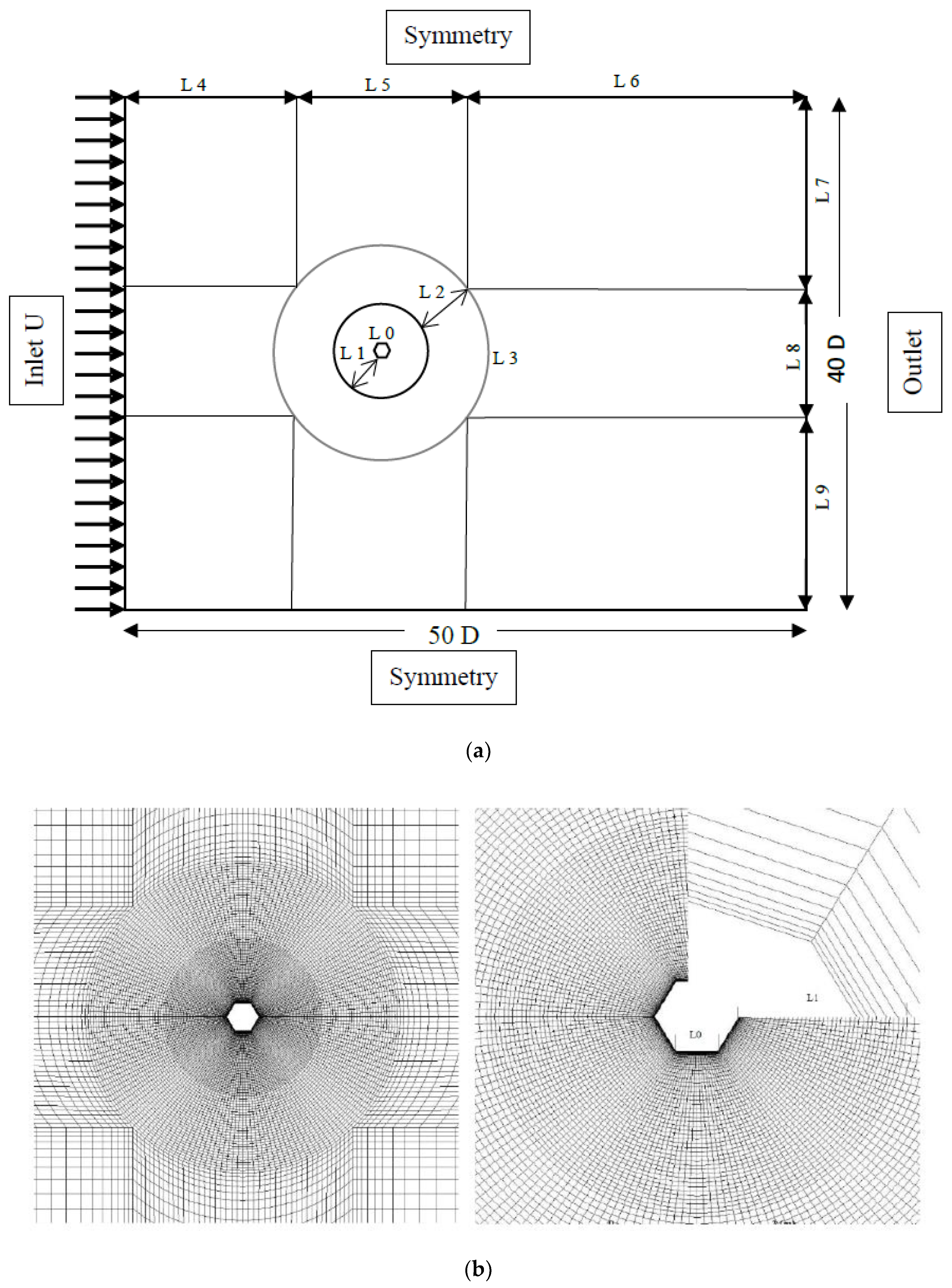
2. Numerical Method: Governing Equations and the Computational Model

Incompressible Reynolds-averaged Navier–Stokes (RANS) equations are used to simulate the flow. To avoid the mesh distortion, the moving boundaries of the cylinder surface are modelled with the Arbitrary Lagrangian Eulerian (ALE) scheme. Assuming u and p represent the time-average values of velocity and pressure, the RANS equations in a Cartesian coordinate system are written as
u i x i = 0 t ( ρ u i ) + x j ( ρ u i u j ) = p x i + x j ( 2 ν S i j u i u j ¯ )
where ν is the viscosity and Sij is the mean stress tensor. The small-scale fluctuations of velocity relating to the turbulence are reduced as u i u j ¯ , which is referred to as the Reynolds stresses. Menter’s [47] shear stress transport (SST) k-ω model, known to accurately capture the adverse pressure gradient flows (because of the concept of elliptic relaxation of ω-equation in the near wall region) is used to model the turbulence in Equation (1). The mean stress rate tensor Sij, and the Reynolds stress tensor u i u j ¯ are
S i j = 1 2 ( u i x j + u j x i ) u i u j ¯ = 2 ν t S i j 2 3 k δ i j
where νt = k/ω is the turbulent viscosity and k is the turbulent energy. Menter’s [47] formulation uses a k-ω model in the inner part of the boundary layer and a k-ε model in the free shear layer, where k is the turbulent kinetic energy, ω is the dissipation rate, and ε is the isotropic dissipation of the turbulence energy. The turbulence kinetic energy is given by
k = 3 2 ( U I ) 2
where I is the turbulence intensity defined by
I = 0.16 ( Re ) 1 8
The specific dissipation rate (ω) is
ω = k 0.5 C μ 0.25 l
where l = 0.07D is the turbulence length and Cμ is an empirical constant approximately equal to 0.09 [48].
The computational mesh with a corner-oriented hexagonal cylinder is shown in Figure 1. The length of the computational domain in the in-line and cross-flow directions are 50D and 40D, respectively [41]. The cylinder is located 20D downstream of the inlet. A free-stream velocity of u = U, v = 0 and in the x-direction is defined at the inlet. The pressure gradient and gradient of the fluid velocity at the outlet reduce to zero and the symmetry boundary conditions are imposed to the top and bottom surfaces. The fluid velocity along the cylinder wall surface is assumed to be the same as the structural speed of vibration of the cylinder (no-slip boundary condition).
The equation of motion of the cylinder in the cross-flow direction (Y) is
m d 2 Y d t 2 + C d Y d t + K Y = F L
where C and K are the structural damping and lateral stiffness constants of the cylinder, respectively and FL is the fluid force on the cylinder in the cross-flow direction (lift force). To get the most adverse vibration responses, the damping constant is set to zero in the current study. In the computational model, a moving mesh zone (dynamic zone) with a diameter of 5D around the cylinder is adopted, and is allowed to move with the cylinder in the cross-flow direction as a rigid body. Transient ANSYS-Fluent [49] package is used to solve the fluid-structure interaction model (Equations (1)–(6)) using an iterative approach. After each time-step, the cylinder and the dynamic zone move in the cross-flow direction, and the displacements of the nodes are calculated based on the Laplace equation [50]
· ( γ S y ) = 0 γ = 1 A
where Sy represents the nodal displacement in the cross-flow direction, γ is a parameter used to avoid excessive deformation of the near-wall elements, and A is the area of the element. No-slip boundary condition on the cylinder surface is adopted [51]. Selection of the time-step in a numerical simulation is a compromise. Trying to cut the time step to achieve a better temporal view would of course increase the computational resources demand. Trying to do so on a coarser mesh would mean fine scale structures would not be captured. Moreover, to get a Courant number less than or equal to 1, a normalized time step of 0.02 is calculated from Δ t = 0.02 D U [52].

3. Numerical Results

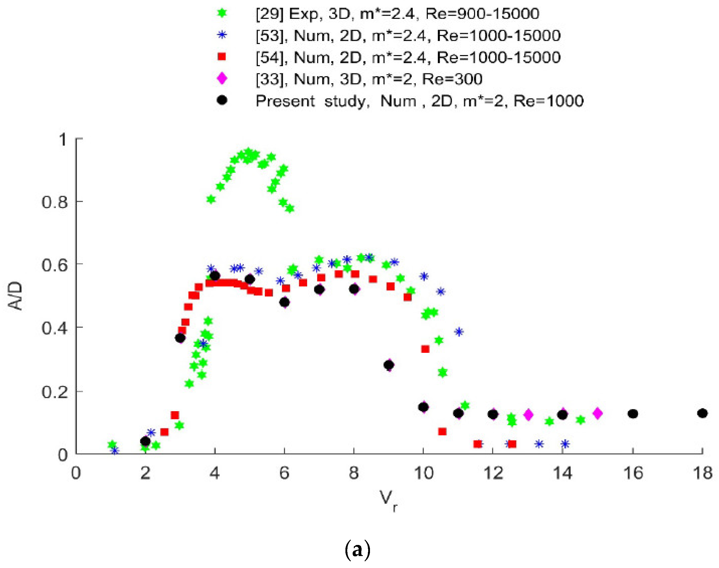
3.1. Validation of the Numerical Model

Numerical results from VIV of a circular cylinder with m* = 2.0 and at Re = 1000 using the model described in the previous section are shown in Figure 2. The normalized amplitudes of vibration (A/D) are plotted against the reduced velocities in Figure 2a. Current results agree well with the published numerical 2D and 3D results in the initial (Vr < 4) and upper branches (4 < Vr < 12). At Vr > 12, the amplitudes calculated from the current and published 2D numerical results [53,54] are lower than the experimental [28] and 3D numerical [32] results.
As can be seen in Figure 2a, most of the numerical models fail to capture the large amplitudes observed in the experimental study of Khalak and Williamson [28] within the upper branch. There are some exceptions to this. In a recent effort by Nikoo et al. [54] (not shown in Figure 2), the RANS-SST k-ω method with low-Re correction was used, and amplitudes of vibration closer to the experimental results within the upper branch were calculated. Pan et al. [51] used a fourth-order Runge-Kutta scheme to integrate the equation of motion (Equation (6)), and used a RNG k-ε turbulence model to solve the governing equations of Equation (1). They report that by reducing the normalized velocity Vr step to increments of 0.025, a normalized amplitude as high as A/D = 0.7 can be reached at Vr = 4.2 [53]. However, they argued that this maximum amplitude did not correspond to a stable state [53]. The current study aims to demonstrate the overall response of hexagonal cylinders with respect to cross-flow vibrations, and to compare it against that of a circular cylinder. Thus, Vr steps of one is used herein.
Knowing that the normalized time is ( t * = t U / D ), the normalized frequencies (f* = fo/fn) of the circular cylinder as a function of the reduced velocity are plotted in Figure 2b. The vibration frequency (fo) is obtained by FFT analysis of the lift force. The lift frequencies are dominated by the natural frequency (fn) and the Strouhal frequency (fst) of the rigid cylinder. The dimensionless Strouhal frequency (fst) (or Strouhal number by adopting D = 1, and U = 1) is equal to f s D / U , where fs is the shedding frequency, and is shown with dashed line. Current results are consistent with experimental results of Khalak and Williamson [28]. At 4 < Vr < 12 (the upper branch), the cylinder vibrates at a constant frequency, which is almost equal to its natural frequency (lock-in region). Outside this region, the vibration frequency follows the Strouhal law. It should be noted that using a smaller reduced velocity step (0.025), Pan et al. [51] observed the lock-in phenomenon at Vr between 4.4 and 11 (similar to the current results).

3.2. Mesh Sensitivity Analysis

In order to obtain the optimum mesh size of the computational model, mesh sensitivity analyses of a rigid circular cylinder at Re = 100, and rigid circular and corner-oriented hexagonal cylinders at Re = 1000 were conducted. Results are represented in Table 1 for four different mesh types. The number of divisions per the length parameter (Li), defined in Figure 1, and the total number of elements for each mesh are given in Table 1. As represented in Table 1 at both Re = 100 and Re = 1000, reasonable accuracy is observed using mesh 3. It can be seen that the root-mean-square lift, mean drag and Strouhal number of mesh 3, agree well with the previously reported results of circular cylinders at Re = 100 [55,56,57]. At Re = 1000 and using mesh 3, Strouhal number of the corner-oriented hexagon is only 0.3% different from the value reported by Khaledi and Andersson [46], using a DNS approach [58]. Moreover, St and CD results obtained with mesh 3 at Re = 1000 agree well with previously reported results. Thus, mesh 3 is adopted herein, and is used to model the vibration response of hexagonal cylinders in corner and face orientations.

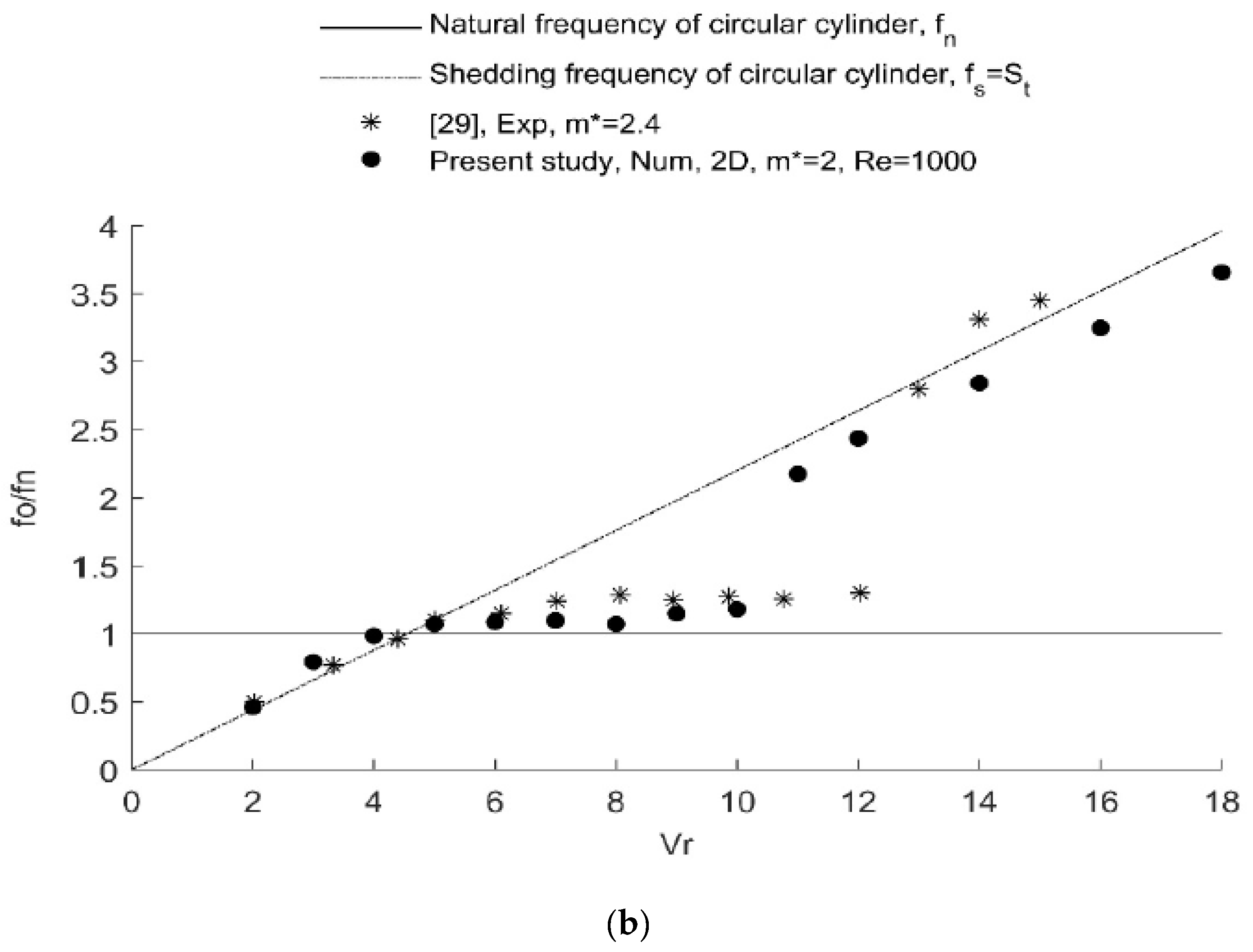
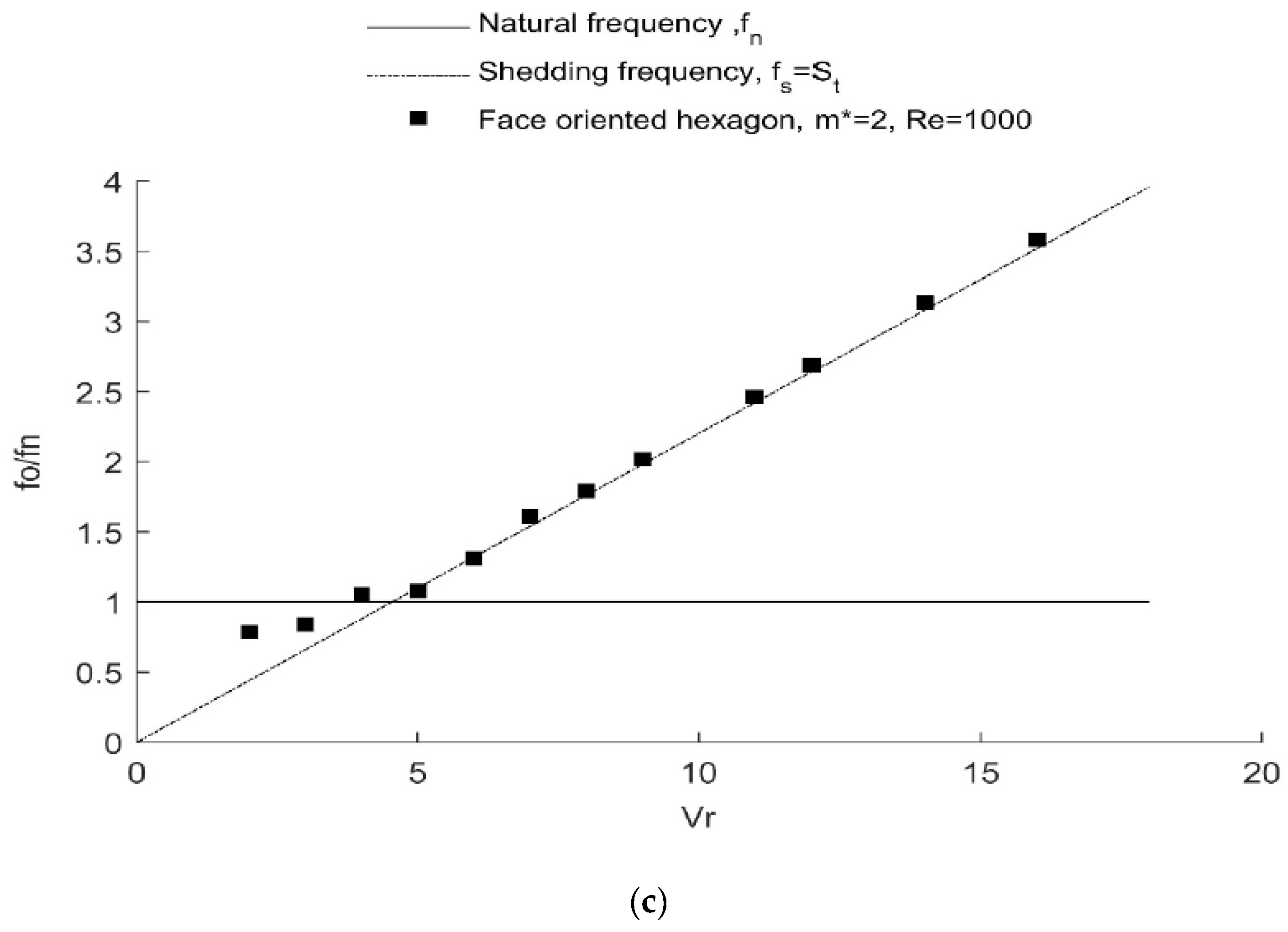
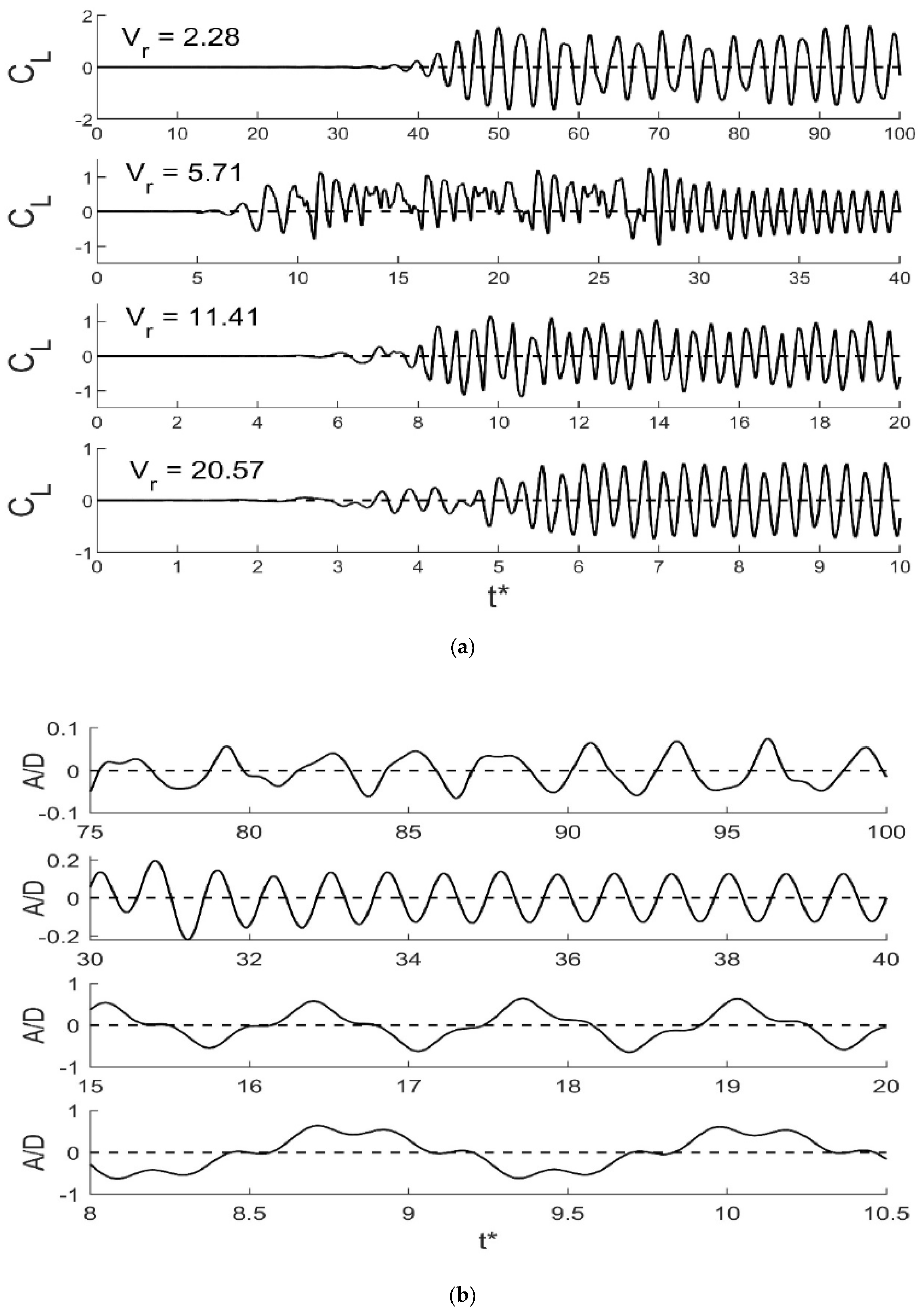
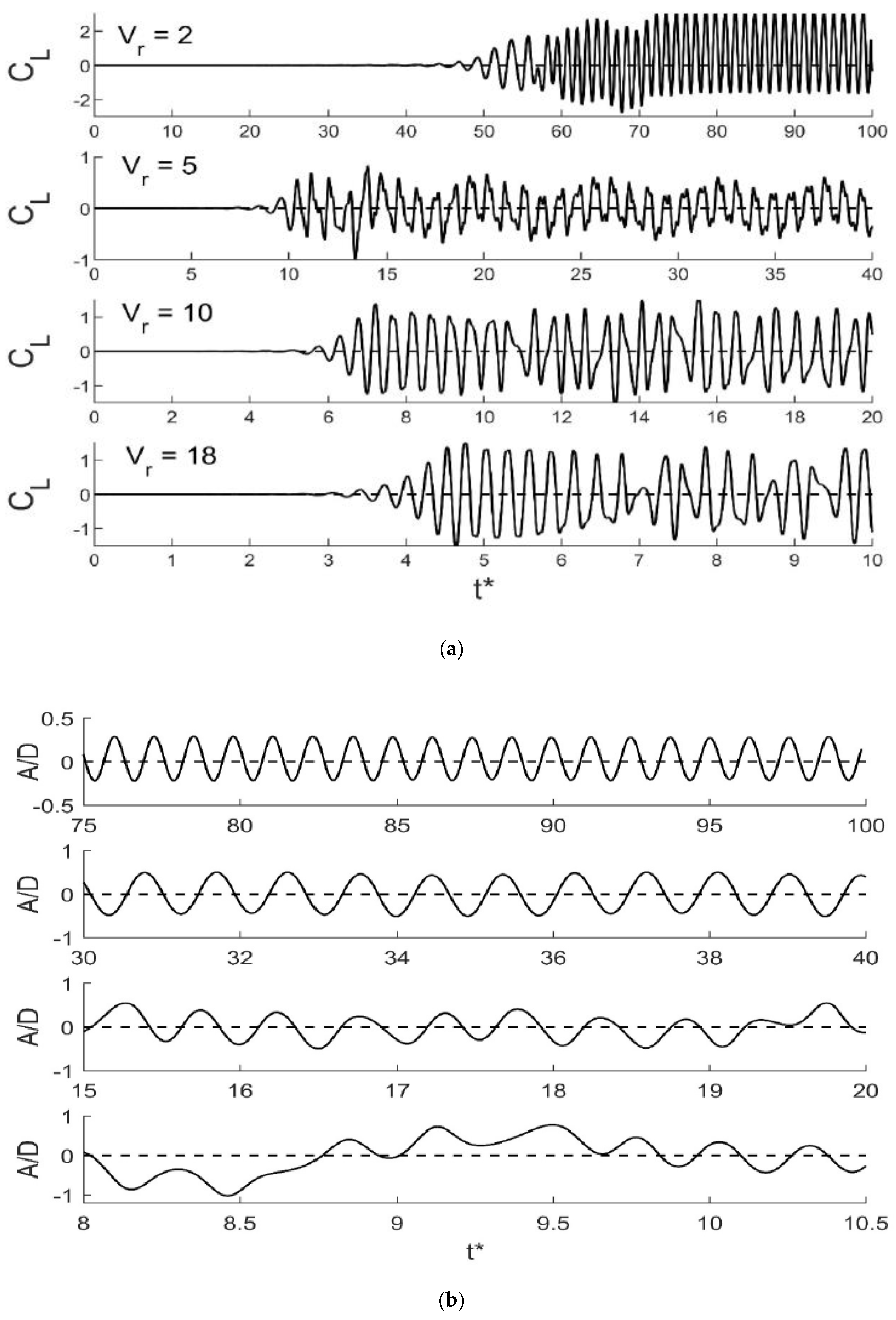
4. One-Degree-of-Freedom Responses of the Hexagonal Cylinders

The VIV responses of circular and hexagonal cylinders with face and corner orientations are plotted in Figure 3 at reduced velocities from 2 to 12, at steps of one, and at steps of two for reduced velocities from 12 to 18. It should be noted that in a corner-orientation, the hexagon has smaller frontal area and therefore a lower corresponding Reynolds number (Re = 867). The difference in Re is reflected in the reduced velocity as well. Therefore, in the corner-oriented hexagon the reduced velocities do not correspond to the exact integers. The normalized amplitudes and frequencies are plotted in Figure 3. It is meaningful to compare the current amplitudes and frequencies with those of a square cylinder at flow approaching angles α of 0° and 45°. For this purpose, the two-degrees-of-freedom response of a square cylinder with m* = 2.0 and Re = 100 conducted by Zhao et al. [41] is selected, and is plotted in Figure 3a.
It can be seen from Figure 3a, that the amplitudes of the hexagonal cylinders are in between those of the squares cylinders with α = 0° (lower bound) and α = 45° (upper bound). At Vr > 14, the amplitudes of the hexagonal and corner-oriented square (α = 45°) cylinders plateau at A/D around 0.4. Whereas, in the circular and face-oriented square (α = 0°) cylinders, the vibration amplitudes show a significant drop. The maximum normalized cross-flow amplitude of a square with α = 0° is equal to 0.35 and occurs at Vr = 5. A normalized amplitude equal to 0.35 is observed in the face-oriented hexagon at Vr = 5 in Figure 3a. Current results show that compared to the corner-oriented square, at Vr < 16, the corner-oriented hexagon has diminished VIV response.
In the corner-oriented hexagon, the amplitude response is comprised of three branches: (a) A lower branch at 3 < Vr < 6, (b) an upper branch at Vr > 12, and (c) a transition zone at reduced velocities between 6 and 12. Normalized amplitudes range from 0.1 to 0.4 in the corner-oriented hexagon. In the face-oriented hexagon, normalized amplitudes as large as 0.2 are observed at reduced velocities as low as Vr = 2. At Vr > 3, the normalized amplitudes fluctuate between 0.3 and 0.45. At Vr < 9, the face-oriented hexagon has larger amplitudes than the corner-oriented hexagon. It is worth to mention that Kumar et al. [62] observed a new extended initial branch in the VIV response of elliptical cylinder at low Re and low mass ratio.
The normalized frequencies of the corner- and face-oriented hexagons are shown in Figure 3b,c, respectively. Vibration frequencies of the hexagonal and face-oriented square cylinders follow the Strouhal law (i.e., the cross-flow vibration frequency is equal to the vortex-shedding frequency) for the entire range of the reduced velocity, and no lock-in is observed. At Vr > 4, the normalized frequencies of the corner-oriented hexagon are above the Strouhal line, whereas, those of the face-oriented hexagon are below it. It should be noted that in the square study [41], lock-in response was only observed in the response of the corner-oriented square (α = 45°) and at 3 < Vr < 10. However, no lock-in response is seen in the hexagonal cylinders.
Time histories of the lift coefficients and vibration amplitudes of the corner-oriented hexagon cylinder are shown in Figure 4 for selected reduced velocities. The normalized time is t * = t f n . In calculation of the lift coefficients, Reynolds numbers, normalized time, and reduced velocities, the projected frontal areas of the cylinders are used. The projected frontal area of the face-oriented hexagons is equal to D, and that of the corner-oriented hexagon is equal to 3 2 D based on a cylinder of unit length. As shown in Figure 4a, at small reduced velocities (Vr < 5), the mean value of the lift coefficient is zero throughout. At larger reduced velocities, although the cylinder configuration is symmetric, the mean value of the lift is non-zero. At Vr = 11.41, the non-zero lift fluctuates from one side of the cylinder to the other side. However, at Vr = 20.57, the mean lift has a negative value. Normalized amplitudes are shown in Figure 4b for selected time domain. Apart from Vr = 2.28, at other reduced velocities regular responses are observed.
The lift time histories of the face-oriented hexagonal cylinders are shown in Figure 5a. At Vr = 2 the mean value of the lift force is non-zero, and is on the positive side of the curve for the timespan considered. However, at Vr = 5 the non-zero lift changes from a positive mean value (32 < t* < 34) to a negative mean value (34 < t* < 36). At larger reduced velocities, the lift force becomes irregular. This irregular behavior is observed in the time history of the vibration amplitudes at larger reduced velocities (Vr = 10, 18), as well (Figure 5b). This phenomenon is related to the vibration modes and will be discussed later.
The phase difference (ϕ) between the lift coefficient and the cross-flow displacement is determined by the FFT analysis of each cylinder at different reduced velocities, and is shown in Figure 6. The phase difference corresponds to the delay between the peak in the amplitude and the peak in the lift force component at the same frequency, and is calculated from the amplitude spectra of the lift force and cross-flow displacement (not shown herein). Phase differences of square cylinders are taken from [41], and are plotted as well. It should be noted that in the corner and face-oriented hexagons, the force and vibration responses are irregular at some reduced velocities (refer to Figure 4 and Figure 5). Therefore, in calculating the phase angles, effort was made to capture a time domain that corresponded to a regular response, when possible. The most distinctive difference between the phase responses of the hexagonal cylinders and the rest, is the emergence of the out of phase response ( ϕ 0 ° ) at low reduced velocities. Similar behavior was reported in the response of a faceted cylinder (textured pipe) [63]. At reduced velocities of 5 and above, the lift force becomes out of phase ( ϕ 180 ° ) with the cross-flow amplitude. The out of phase response was reported to occur at Vr = 7 and Vr = 9, in the flat and corner-oriented squares, respectively (Figure 6). Fluctuations in the phase angles of the hexagonal cylinders are observed at 10 < Vr < 16. This is more evident in the face-oriented hexagon, where a phase angle of ϕ = 165° is seen at Vr = 14.

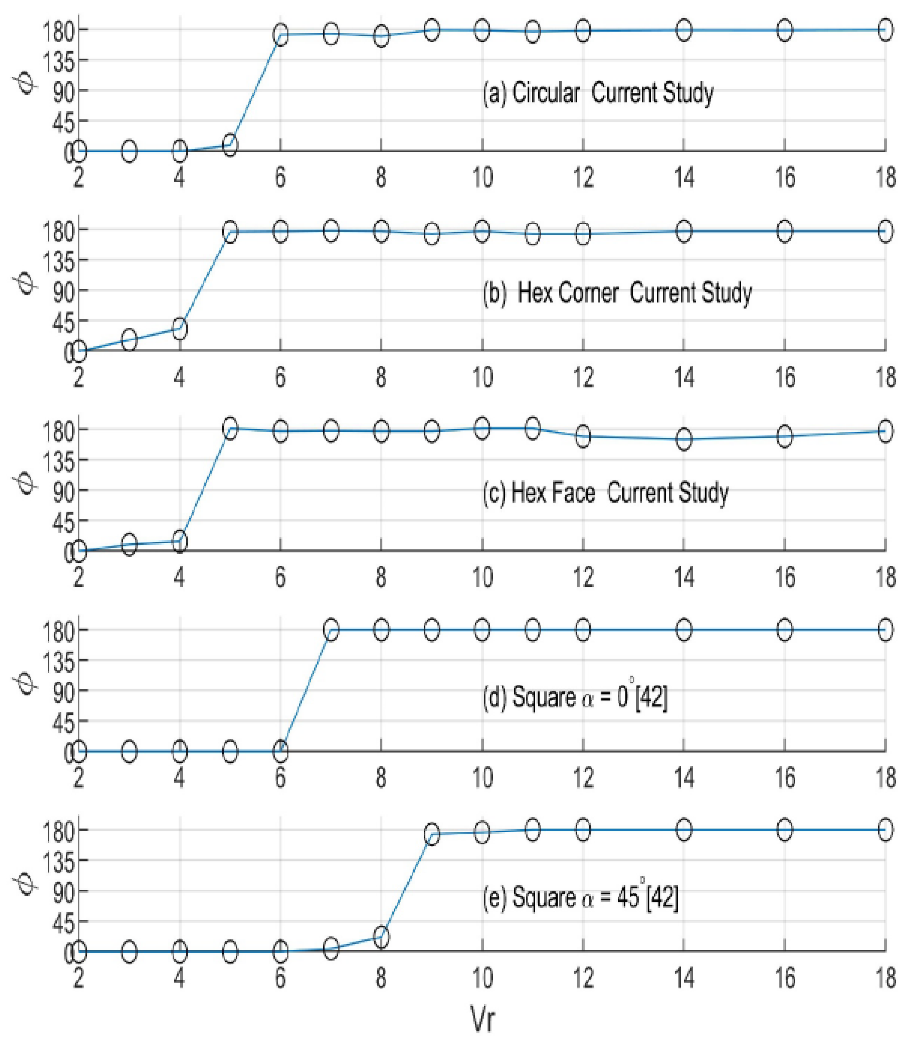
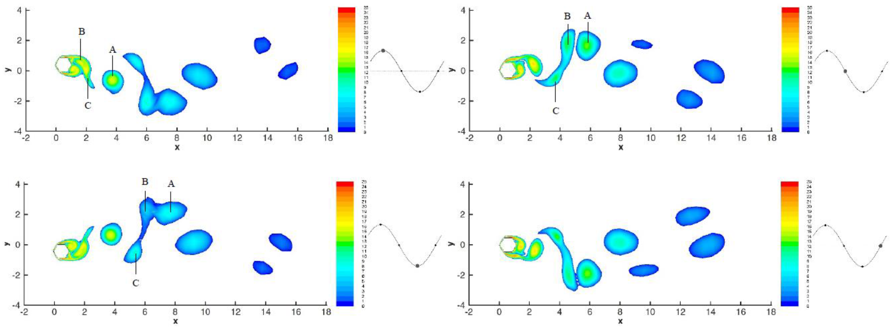
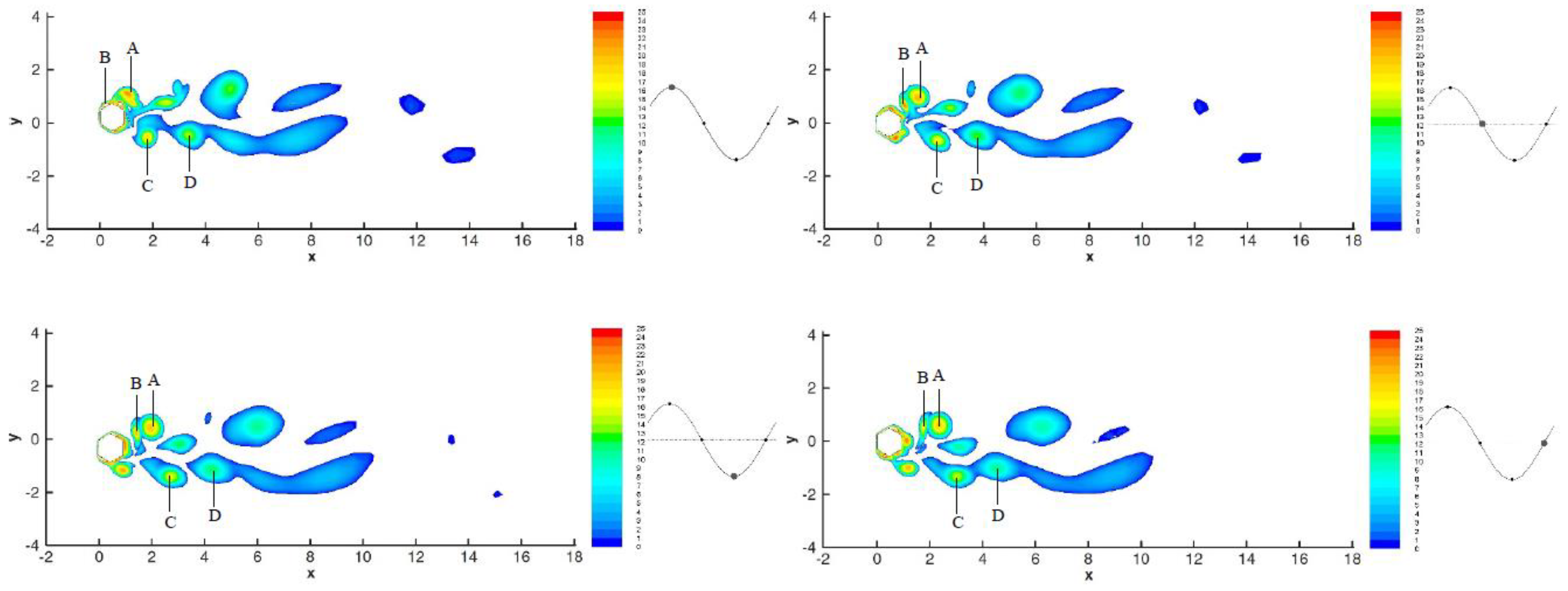
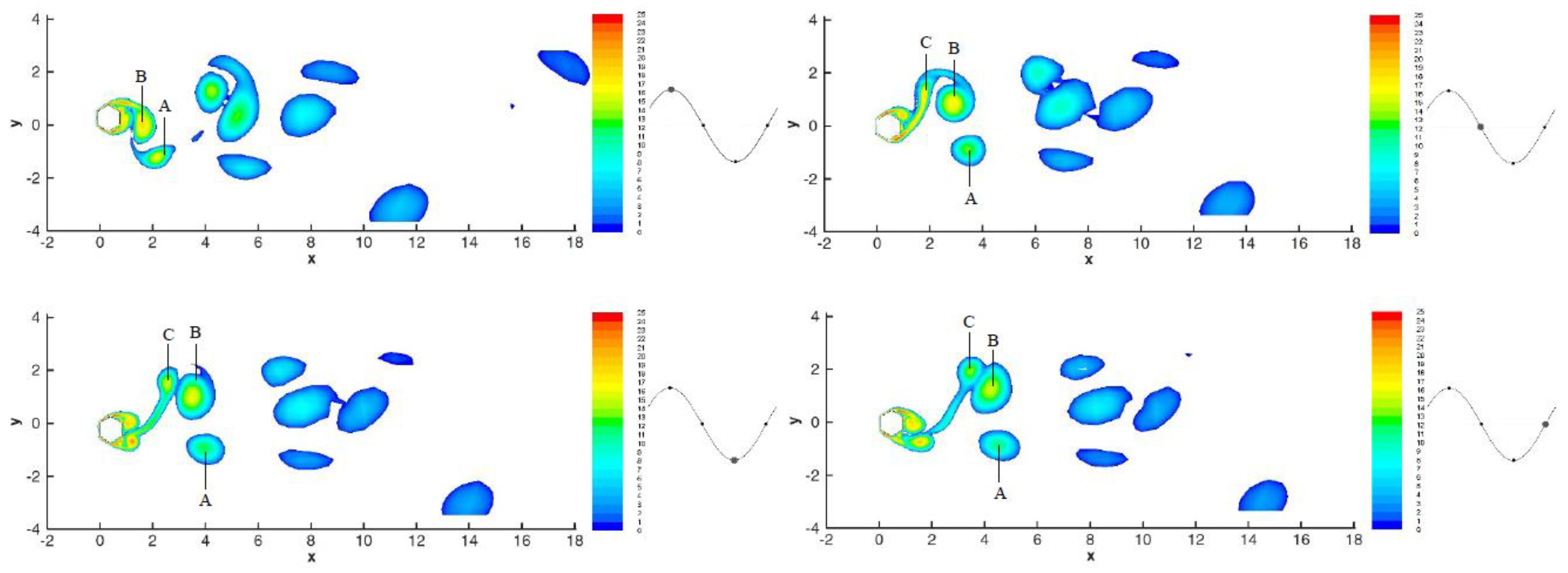
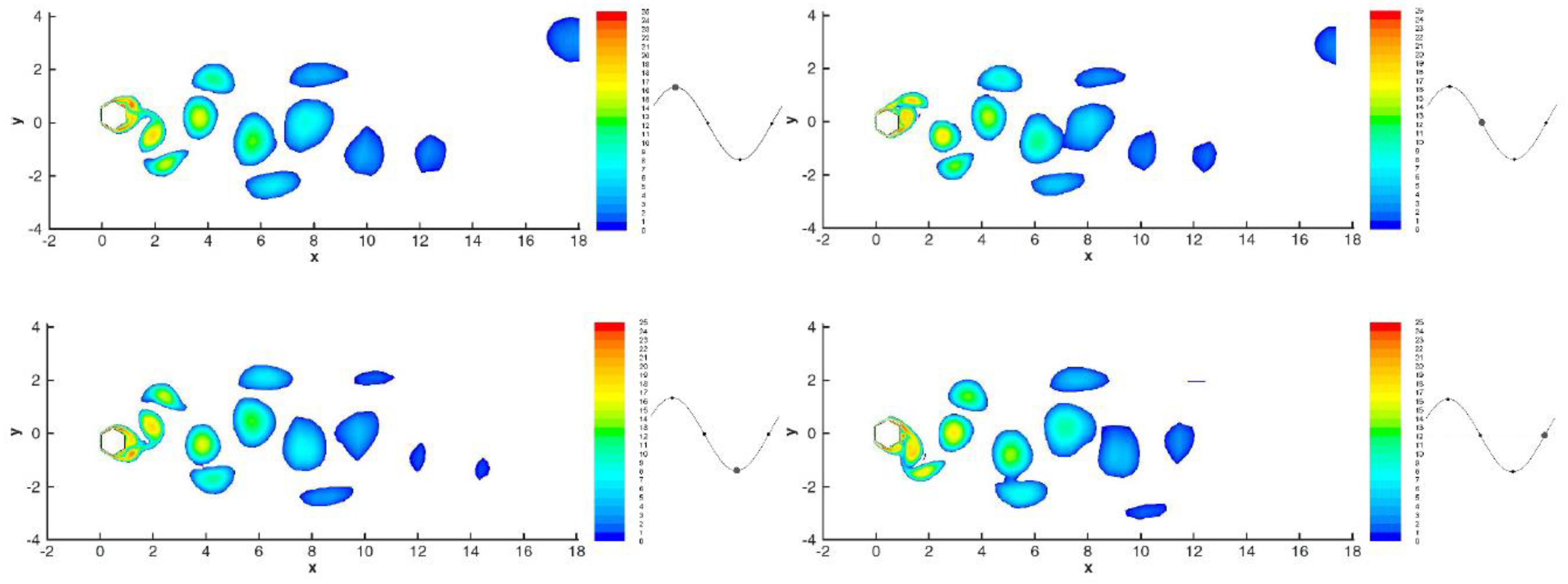
5. Vortex Shedding Regime

Figure 7 shows the vorticity contours of the corner-oriented hexagon at Vr = 2.28, at four instants in one vibration period during which the normalized vibration frequency is 0.346 and the normalized amplitude is 0.03. The trajectory of the cylinder in the xy plane, and its instant position are depicted next to each vortex contour. The legends are provided for comparison between the vorticity magnitudes. Vortex C is shed from the top of the cylinder as it is moving from the top to the bottom of the trajectory. At this instant two positive vortices (A and B) are already shed from the bottom of the cylinder, and are located between 2–4 D in the wake. As the cylinder moves down the trajectory, the vortices A and B merge and move further down the wake. While the cylinder is at its lowest trajectory position, three vortices (one positive and two negative) are being shed. At the end of the vibration period, vortices A and B are merged into a single vortex, and are followed by vortex C. As can be seen in Figure 7, the vortex regime of the corner-oriented hexagon at this small reduced velocity changes from a P + S mode (pair A + B and single C), to a 2S mode (C and A + B).
Vortex regimes of the corner-oriented hexagon at Vr = 11.41, corresponding to frequency and amplitude of 2.4 and 0.35, respectively, are shown in Figure 8. One pair (B and C) and one single (A) vortex are shed in each vortex shedding period, describing a P + S mode. The shedding frequency is twice the vibration frequency. When the cylinder moves down the trajectory, the P + S is shed from the top, and when the cylinder moves upward, a new P + S is generated from the bottom. The P and S vortices have different sizes but similar strengths. As predicted from Figure 3b, the vibration frequency is smaller than the Strouhal frequency.
Figure 9 shows the vortex regime of the corner-oriented hexagon at Vr = 20.57. At this reduced velocity, the vibration frequency is significantly lower than the Strouhal frequency and is 3.5 times larger than the natural frequency of the cylinder. The vibration amplitude (Figure 3a) at Vr = 20.57 is not much different from the amplitude at Vr = 11.41. However, the vortex regimes at those reduced velocities are dissimilar. As shown in Figure 9, four vortices (labelled by A-D) are shed from the cylinder in each vibration period. These vortices have different sizes and magnitudes and do not pair up behind the cylinder. Zhao et al. [41] reported similar vortex regime in a square cylinder at α = 22.5°, with Vr = 7 (outside the lock-in region).
Figure 10 shows vortex regime of the face-oriented hexagon at Vr = 2, at which the normalized amplitude and frequency of vibration are 0.17 and 0.79, respectively. As the cylinder moves down from the peak point, a pair of vortices (A + B) are shed from the top. This pair follows two vortices (labelled by C and D) at the bottom. At the end of the vibration period, a new pair of vortices is being shed from the bottom of the cylinder. The P + 2S formation observed here is significantly different from that of the corner-oriented hexagon at the same reduce velocity. The four vortices progress slowly in the rear of the cylinder (almost 1D in a vibration period). The pair (A + B) has larger vorticity and is shed while the cylinder moves down the trajectory. The single vortices (C and D) are not as strong and move below y = 0 line, throughout the wake. This P + 2S mode is different from typical mode. As seen in Figure 10, another single vortex of smaller vorticity is detached from the pair (A + B), at half-period.
The vortex regime of the face-oriented hexagon at Vr = 10, is shown in Figure 11, and clearly depicts a P + S mode in one vibration period. The already generated single vortex at the bottom (A), moves in the bottom rear wake of the cylinder, while a pair (C + B) is shed from the top. It can be seen that at the end of the period, a new pair of vortices are being developed at the bottom of the cylinder. Comparison between Figure 11 and Figure 8 at (10 < Vr < 12) shows that in a P + S vortex regime mode, the amplitudes and frequencies of vibration of the hexagons in corner and face orientations are almost equal. At similar amplitudes (0.2 < A* < 0.3), Zhao et al. [41] reported a 2S mode for a circular cylinder with α = 0°.
Figure 12 shows the vortex regime of the face-oriented hexagon at Vr = 18. Four vortices in two pairs (2P mode) are shed within each vibration cycle. The current regime is a typical 2P mode, and the two pair of vortices that are shed from the cylinder in each vibration period, are symmetric about an imaginary y = 0 line. Toward the end of the vibration cycle, and at a distance of 8D in the rear wake, the pair of vortices still have high vorticity. This explains the high amplitude and frequency of vibration, and the irregular lift and amplitude responses of the face-oriented hexagon at large reduced velocities.

6. Conclusions

One degree of freedom VIV response of hexagonal cylinders in corner and face orientations at Re = 1000 and at low mass ratio of m* = 2 were investigated using numerical simulations at reduced velocities up to 20. Results were compared against a published numerical work on VIV of square cylinders at low Reynolds number and mass ratio [41]. Unlike square cylinders, no lock-in region was observed in the VIV responses of the hexagonal cylinders at the studied reduced velocities. Normalized frequencies (vibration frequency divided by the natural frequency) of the corner-oriented hexagon were found to be dominantly below the Strouhal frequency (fs), whereas, in the face-oriented hexagon, the normalized frequencies were slightly larger than fs.
Within the studied reduced velocity range, the maximum normalized cross-flow amplitude of vibration of the hexagonal cylinders were shown to be around 0.45. This is significantly lower than the reported maximum amplitudes of 0.96 for circular cylinder [28] and 0.925 for corner-oriented square cylinder [41]. At large reduced velocities, similar amplitudes (around 0.4) were observed in the corner-oriented square and hexagonal cylinders. Unlike other cylinders, phase differences between amplitude and lift forces ( ϕ 0 ° ) were seen in the hexagonal cylinders, at low reduced velocities. The phase difference settled at ϕ 180 ° in the corner-oriented hexagon at large reduced velocities. However, fluctuations were seen in the phase differences of the face-oriented hexagon.
The vortex shedding regimes of the face-oriented hexagons were more similar to the typical modes reported in the literature, compared with the corner-oriented hexagon. At low reduced velocities (and low amplitudes), P + S modes were observed in the corner-oriented hexagon. At large amplitudes, four non-pairing vortices of different sizes and magnitudes were observed in the corner-oriented hexagon, similar to observations of Zhao et al. [41] of a corner-oriented square at large amplitudes. P + 2S modes were observed in the face-oriented hexagon, and explained the existence of sizeable vibration amplitudes at low reduced velocities. At larger reduced velocities, P + S modes were observed, and clarified the larger amplitudes of face-oriented hexagon compared to flat square cylinders with 2S modes reported in [41]. At very large reduced velocities distinct 2P modes were seen, and were shown to have significant vorticity magnitudes in a distance as far as 8D in the rear wake of the face-oriented cylinder.

Author Contributions

F.P.: Conceptualization, Methodology, Investigation, Writing – original draft. H.K.: Conceptualization, Methodology, Supervision, Data curation, Project administration, Writing—review & editing. P.W.: Supervision, Writing—review & editing. All authors have read and agreed to the published version of the manuscript.

Funding

This research received no external funding.

Conflicts of Interest

The authors declare no conflict of interest.

References

  1. Hayashida, H.; Iwasa, Y. Aerodynamic shape effects of tall building for vortex induced vibration. J. Wind Eng. Ind. Aerodyn. 1990, 33, 237–242. [Google Scholar] [CrossRef]
  2. Wang, L.; Liang, S.-G.; Huang, G.; Song, J.; Zou, L. Investigation on the unstability of vortex induced resonance of high-rise buildings. J. Wind Eng. Ind. Aerodyn. 2018, 175, 17–31. [Google Scholar] [CrossRef]
  3. Matsumoto, M.; Yagi, T.; Shigemura, Y.; Tsushima, D. Vortex-induced cable vibration of cable-stayed bridges at high reduced wind velocity. J. Wind Eng. Ind. Aerodyn. 2001, 89, 633–647. [Google Scholar] [CrossRef]
  4. Fujino, Y.; Yoshida, Y. Wind-Induced Vibration and Control of Trans-Tokyo Bay Crossing Bridge. J. Struct. Eng. 2002, 128, 1012–1025. [Google Scholar] [CrossRef]
  5. Wang, W.; Wang, X.; Hua, X.; Song, G.; Chen, Z. Vibration control of vortex-induced vibrations of a bridge deck by a single-side pounding tuned mass damper. Eng. Struct. 2018, 173, 61–75. [Google Scholar] [CrossRef]
  6. Carlson, D.W.; Modarres-Sadeghi, Y. Vortex-induced vibration of spar platforms for floating offshore wind turbines. Wind Energy 2018, 21, 1169–1176. [Google Scholar] [CrossRef]
  7. Datta, N. Vortex-induced vibration of a tension leg platform tendon: Multi-mode limit cycle oscillations. J. Mar. Sci. Appl. 2017, 16, 458–464. [Google Scholar] [CrossRef]
  8. Trim, A.; Braaten, H.; Lie, H.; Tognarelli, M. Experimental investigation of vortex-induced vibration of long marine risers. J. Fluids Struct. 2005, 21, 335–361. [Google Scholar] [CrossRef]
  9. Chaplin, J.; Bearman, P.; Cheng, Y.; Fontaine, E.; Graham, J.; Herfjord, K.; Huera-Huarte, F.; Isherwood, M.; Lambrakos, K.; Larsen, C.; et al. Blind predictions of laboratory measurements of vortex-induced vibrations of a tension riser. J. Fluids Struct. 2005, 21, 25–40. [Google Scholar] [CrossRef]
  10. Song, L.; Fu, S.; Cao, J.; Ma, L.; Wu, J. An investigation into the hydrodynamics of a flexible riser undergoing vortex-induced vibration. J. Fluids Struct. 2016, 63, 325–350. [Google Scholar] [CrossRef]
  11. Kang, L.; Ge, F.; Wu, X.; Hong, Y. Experiments and Modeling on the Maximum Displacement of a Long Tensioned Mooring Tether Subjected to Vortex-induced Vibration. Procedia Eng. 2016, 166, 83–90. [Google Scholar] [CrossRef]
  12. Van Dijk, R.R.T.; Voogt, A.; Fourchy, P.; Mirza, S. The Effect of Mooring System and Sheared Currents on Vortex Induced Motions of Truss Spars. In Proceedings of the ASME 2003 22nd International Conference on Offshore Mechanics and Arctic Engineering, Cancun, Mexico, 8–13 June 2003; pp. 285–292. [Google Scholar]
  13. Skop, R.A.; Griffin, O.M.; Ramberg, S.E. Strumming Predictions for the Seacon Ii Experimental Mooring. In Proceedings of the Offshore Technology Conference, Houston, TX, USA, 2–5 May 1977. [Google Scholar]
  14. Larsen, C.M.; Passano, E.; Baarholm, G.S.; Koushan, K. Non-Linear Time Domain Analysis of Vortex Induced Vibrations for Free Spanning Pipelines. In Proceedings of the ASME 2004 23rd International Conference on Offshore Mechanics and Arctic Engineering, Vancouver, BC, Canada, 20–25 June 2004; pp. 207–215. [Google Scholar]
  15. Kapuria, S.; Salpekar, V.Y.; Sengupta, S. Fatigue due to vortex-induced crossflow oscillations in free spanning pipelines supported on elastic soil bed. In Proceedings of the Ninth International Offshore and Polar Engineering Conference, Brest, France, 30 May–4 June 1999; International Society of Offshore and Polar Engineers: Mountain View, CA, USA. [Google Scholar]
  16. Jin, Y.; Dong, P. A novel Wake Oscillator Model for simulation of cross-flow vortex induced vibrations of a circular cylinder close to a plane boundary. Ocean Eng. 2016, 117, 57–62. [Google Scholar] [CrossRef]
  17. Weaver, D.; Fitzpatrick, J. A review of cross-flow induced vibrations in heat exchanger tube arrays. J. Fluids Struct. 1988, 2, 73–93. [Google Scholar] [CrossRef]
  18. Chen, S. Crossflow-induced vibrations of heat exchanger tube banks. Nucl. Eng. Des. 1978, 47, 67–86. [Google Scholar] [CrossRef]
  19. Izadpanah, E.; Amini, Y.; Ashouri, A. A comprehensive investigation of vortex induced vibration effects on the heat transfer from a circular cylinder. Int. J. Therm. Sci. 2018, 125, 405–418. [Google Scholar] [CrossRef]
  20. Paidoussis, M. A review of flow-induced vibrations in reactors and reactor components. Nucl. Eng. Des. 1983, 74, 31–60. [Google Scholar] [CrossRef]
  21. Weaver, D.S.; Ziada, S.; Au-Yang, M.K.; Chen, S.S.; Paıdoussis, M.P.; Pettigrew, M.J. Flow-Induced Vibrations in Power and Process Plant Components—Progress and Prospects. J. Press. Vessel Technol. 2000, 122, 339–348. [Google Scholar] [CrossRef]
  22. Wille, R. Karman vortex streets. In Advances in Applied Mechanics; Elsevier: New York, NY, USA, 1960; Volume 6, pp. 273–287. [Google Scholar]
  23. Vandiver, J.K.; Swithenbank, S.B.; Jaiswal, V.; Jhingran, V. Fatigue Damage from High Mode Number Vortex-Induced Vibration. In Proceedings of the 25th International Conference on Offshore Mechanics and Arctic Engineering, Hamburg, Germany, 4–9 June 2006; pp. 803–811. [Google Scholar]
  24. Blevins, R.D. Flow-Induced Vibration; Van Nostrand Reinhold Co.: New York, NY, USA, 1977; 377p. [Google Scholar]
  25. Feng, C.C. The Measurement of Vortex Induced Effects in Flow past Stationary and Oscillating Circular and D-Section Cylinders. Ph.D. Thesis, University of British Columbia, Vancouver, BC, Canada, 1968. [Google Scholar]
  26. Khalak, A.; Williamson, C. Fluid forces and dynamics of a hydroelastic structure with very low mass and damping. J. Fluids Struct. 1997, 11, 973–982. [Google Scholar] [CrossRef]
  27. Khalak, A.; Williamson, C.H. Investigation of relative effects of mass and damping in vortex-induced vibration of a circular cylinder. J. Wind Eng. Ind. Aerodyn. 1997, 69, 341–350. [Google Scholar] [CrossRef]
  28. Khalak, A.; Williamson, C. Motions, forces and mode transitions in vortex-induced vibrations at low mass-damping. J. Fluids Struct. 1999, 13, 813–851. [Google Scholar] [CrossRef]
  29. Jauvtis, N.; Williamson, C.H.K. The effect of two degrees of freedom on vortex-induced vibration at low mass and damping. J. Fluid Mech. 2004, 509, 23–62. [Google Scholar] [CrossRef]
  30. Jeon, D.; Gharib, M. On circular cylinders undergoing two-degree-of-freedom forced motions. J. Fluids Struct. 2001, 15, 533–541. [Google Scholar] [CrossRef]
  31. Pan, Z.; Cui, W.; Miao, Q. Numerical simulation of vortex-induced vibration of a circular cylinder at low mass-damping using RANS code. J. Fluids Struct. 2007, 23, 23–37. [Google Scholar] [CrossRef]
  32. Zhao, M.; Cheng, L.; An, H.; Lu, L. Three-dimensional numerical simulation of vortex-induced vibration of an elastically mounted rigid circular cylinder in steady current. J. Fluids Struct. 2014, 50, 292–311. [Google Scholar] [CrossRef]
  33. Zhao, M.; Cheng, L. Numerical simulation of two-degree-of-freedom vortex-induced vibration of a circular cylinder close to a plane boundary. J. Fluids Struct. 2011, 27, 1097–1110. [Google Scholar] [CrossRef]
  34. Menter, F.R. Review of the shear-stress transport turbulence model experience from an industrial perspective. Int. J. Comput. Fluid Dyn. 2009, 23, 305–316. [Google Scholar] [CrossRef]
  35. Ji, C.; Xiao, Z.; Wang, Y.; Wang, H. Numerical investigation on vortex-induced vibration of an elastically mounted circular cylinder at low Reynolds number using the fictitious domain method. Int. J. Comput. Fluid Dyn. 2011, 25, 207–221. [Google Scholar] [CrossRef]
  36. Prasanth, T.; Behara, S.; Singh, S.; Kumar, R.; Mittal, S. Effect of blockage on vortex-induced vibrations at low Reynolds numbers. J. Fluids Struct. 2006, 22, 865–876. [Google Scholar] [CrossRef]
  37. Bearman, P.; Gartshore, I.; Maull, D.; Parkinson, G. Experiments on flow-induced vibration of a square-section cylinder. J. Fluids Struct. 1987, 1, 19–34. [Google Scholar] [CrossRef]
  38. Amandolèse, X.; Hémon, P. Vortex-induced vibration of a square cylinder in wind tunnel. C. R. Méc. 2010, 338, 12–17. [Google Scholar] [CrossRef]
  39. Zhao, J.; Nemes, A.; Jacono, D.L.; Sheridan, J. The effect of incidence angle variation of a square cylinder on its dynamic response and wake states. In Proceedings of the 17th Australasian Fluid Mechanics Conference, Auckland, New Zealand, 5–9 December 2010; pp. 724–727. [Google Scholar]
  40. Corless, R.M.; Parkinson, G. A model of the combined effects of vortex-induced oscillation and galloping. J. Fluids Struct. 1988, 2, 203–220. [Google Scholar] [CrossRef]
  41. Zhao, M.; Cheng, L.; Zhou, T. Numerical simulation of vortex-induced vibration of a square cylinder at a low Reynolds number. Phys. Fluids 2013, 25, 023603. [Google Scholar] [CrossRef]
  42. Kawatani, M.; Toda, N.; Sato, M.; Kobayashi, H. Vortex-induced torsional oscillations of bridge girders with basic sections in turbulent flows. J. Wind Eng. Ind. Aerodyn. 1999, 83, 327–336. [Google Scholar] [CrossRef]
  43. De Ridder, J.; Van Tichelen, K.; Degroote, J.; Vierendeels, J. Vortex-induced vibrations by axial flow in a bundle of cylinders. In Proceedings of the 11th International Conference on Flow-Induced Vibration, Hague, The Netherlands, 4–6 July 2016; pp. 1–8. [Google Scholar]
  44. Karampour, H.; Wu, Z.; Lefebure, J.; Jeng, D.-S.; Etemad-Shahidi, A.; Simpson, B. Modelling of flow around hexagonal and textured cylinders. Proc. Inst. Civ. Eng. Eng. Comput. Mech. 2018, 171, 99–114. [Google Scholar] [CrossRef] [Green Version]
  45. Tian, Z.W.; Wu, Z. A study of two-dimensional flow past regular polygons via conformal mapping. J. Fluid Mech. 2009, 628, 121. [Google Scholar] [CrossRef]
  46. Khaledi, H.A.; Andersson, H.I. On vortex shedding from a hexagonal cylinder. Phys. Lett. A 2011, 375, 4007–4021. [Google Scholar] [CrossRef] [Green Version]
  47. Menter, F.R. Two-equation eddy-viscosity turbulence models for engineering applications. AIAA J. 1994, 32, 1598–1605. [Google Scholar] [CrossRef] [Green Version]
  48. Rahman, M.; Karim, M.; Alim, A. Numerical investigation of unsteady flow past a circular cylinder using 2-D finite volume method. J. Nav. Arch. Mar. Eng. 2007, 4, 27–42. [Google Scholar] [CrossRef] [Green Version]
  49. Ansys® Academic Research Fluent, Release 19.1. Available online: https://www.ansys.com/products/release-highlights (accessed on 28 April 2020).
  50. Masud, A. Effects of Mesh Motion on the Stability and Convergence of ALE Based Formulations for Moving Boundary Flows. Comput. Mech. 2006, 38, 430–439. [Google Scholar] [CrossRef]
  51. Pan, Y.; Banerjee, S. Numerical simulation of particle interactions with wall turbulence. Phys. Fluids 1996, 8, 2733–2755. [Google Scholar] [CrossRef]
  52. Nishino, T.; Roberts, G.; Zhang, X. Unsteady RANS and detached-eddy simulations of flow around a circular cylinder in ground effect. J. Fluids Struct. 2008, 24, 18–33. [Google Scholar] [CrossRef] [Green Version]
  53. Guilmineau, E.; Queutey, P. Numerical simulation of vortex-induced vibration of a circular cylinder with low mass-damping in a turbulent flow. J. Fluids Struct. 2004, 19, 449–466. [Google Scholar] [CrossRef]
  54. Nikoo, H.M.; Bi, K.; Hao, H. Three-dimensional vortex-induced vibration of a circular cylinder at subcritical Reynolds numbers with low-Re correction. Mar. Struct. 2019, 66, 288–306. [Google Scholar] [CrossRef]
  55. Linnick, M.N.; Fasel, H. A high-order immersed interface method for simulating unsteady incompressible flows on irregular domains. J. Comput. Phys. 2005, 204, 157–192. [Google Scholar] [CrossRef]
  56. Berthelsen, P.A.; Faltinsen, O.M. A local directional ghost cell approach for incompressible viscous flow problems with irregular boundaries. J. Comput. Phys. 2008, 227, 4354–4397. [Google Scholar] [CrossRef]
  57. Williamson, C.; Roshko, A. Vortex formation in the wake of an oscillating cylinder. J. Fluids Struct. 1988, 2, 355–381. [Google Scholar] [CrossRef]
  58. Manhart, M. A zonal grid algorithm for DNS of turbulent boundary layers. Comput. Fluids 2004, 33, 435–461. [Google Scholar] [CrossRef]
  59. Roshko, A. Experiments on the flow past a circular cylinder at very high Reynolds number. J. Fluid Mech. 1961, 10, 345–356. [Google Scholar] [CrossRef] [Green Version]
  60. Ku, H.-C. Solution of Flow in Complex Geometries by the Pseudospectral Element Method. J. Comput. Phys. 1995, 117, 215–227. [Google Scholar] [CrossRef]
  61. Zukauskas, A.; Ziugzda, J. Heat Transfer of a Cylinder in Crossflow; Hemisphere Publishing: New York, NY, USA, 1985. [Google Scholar]
  62. Sourav, K.; Kumar, D.; Sen, S. Vortex-induced vibrations of an elliptic cylinder of low mass ratio: Identification of new response branches. Phys. Fluids 2020, 32, 023605. [Google Scholar] [CrossRef]
  63. Nikoo, H.M.; Bi, K.; Hao, H. Textured pipe-in-pipe system: A compound passive technique for vortex-induced vibration control. Appl. Ocean Res. 2020, 95, 102044. [Google Scholar] [CrossRef]
Figure 1. The computational model, showing: (a) Parameters used in the mesh convergence study, and (b) computational mesh near the corner-oriented hexagonal cylinder.
Jmse 08 00387 g001
Figure 2. The VIV response of a circular cylinder, comparison between the current and published results, showing: (a) Normalized vibration amplitude vs. reduced velocity, and (b) normalized frequency vs. reduced velocity.
Jmse 08 00387 g002aJmse 08 00387 g002b
Figure 3. The VIV response of a circular and hexagonal cylinder at different reduced velocities, (a) normalized amplitudes, (b) normalized frequency for corner-oriented hexagon, and (c) normalized frequency for face-oriented hexagon.
Jmse 08 00387 g003aJmse 08 00387 g003b
Figure 4. Time histories of the (a) lift coefficient and (b) normalized amplitudes of the corner-oriented hexagonal at Vr = 2.28, Vr = 5.71, Vr = 11.41, and Vr = 20.57.
Jmse 08 00387 g004
Figure 5. Time histories of the (a) lift coefficient and (b) normalized amplitudes of the face-oriented hexagonal at Vr = 2, Vr = 5, Vr = 10, and Vr = 18.
Jmse 08 00387 g005
Figure 6. Phase differences between the lift force and cross-flow vibration displacement.
Jmse 08 00387 g006
Figure 7. Vorticity contours at four instants in a vibration period of the corner-oriented hexagonal cylinder at Vr = 2.28 at 93.02 < t* < 95.92.
Jmse 08 00387 g007
Figure 8. Vorticity contours at four instants in a vibration period of the corner-oriented hexagonal cylinder at Vr = 11.41 at 18.18 < t* < 19.51.
Jmse 08 00387 g008
Figure 9. Vorticity contours at four instants in a vibration period of the corner-oriented hexagonal cylinder at Vr = 20.57 at 9.25 < t* < 10.40.
Jmse 08 00387 g009
Figure 10. Vorticity contours at four instants in a vibration period of the face-oriented hexagonal cylinder at Vr = 2 at 83.23 < t* < 93.70.
Jmse 08 00387 g010
Figure 11. Vorticity contours at four instants in a vibration period of the face-oriented hexagonal cylinder at Vr = 10 at 21.32 < t* < 21.92.
Jmse 08 00387 g011
Figure 12. Vorticity contours at four instants in a vibration period of the face-oriented hexagonal cylinder at Vr = 18 at 4.70 < t* < 4.96.
Jmse 08 00387 g012
Table 1. Mesh dependence study of circular and hexagonal rigid cylinders using the computational model of Figure 1.
CaseNumber of DivisionsTotal Number of ElementsRe = 100 Circular CylinderRe = 1000 Circular CylinderRe = 1000 Corner-Oriented Hexagonal Cylinder
L0L4L5L6 RMS CLMean CDStStMean CDStMean CD
Linnick and Fasel [55]-----0.3331.3400.166----
Berthelsen and Faltinsen [56]-----0.3401.3801.169----
Williamson and Roshko [57]-------0.164----
Khaledi and Andersson (DNS) [46]----------0.1718-
Roshko (Exp) [59]--------0.211.2--
Ku [60]--------0.2331.17--
Zukauskas and Ziugzda [61]-------- 1.20--
This study (mesh 1)2025303513,3820.3471.3810.161--0.17322.145
This study (mesh 2)2530354018,1400.3391.3630.163--0.17291.716
This study (mesh 3)3040455030,5200.3331.3520.1630.2201.2000.17241.492
This study (mesh 4)3545555535,9500.3301.3480.163--0.17231.427
Note: in Figure 1: L1 = 2 × L0, L2 = L1, L3 = 6 × L0, L7 = L4, L8 = L5, L9 = L7.

