A Study of the Movement, Structural Stability, and Electrical Performance for Harvesting Ocean Kinetic Energy Based on IPMC Material

1
Faculty of Vehicle and Energy Engineering, Phenikaa University, To Huu Street, Yen Nghia Ward, Ha Dong District, Hanoi 100000, Vietnam
2
Department of Mechanical Engineering and High Safety Vehicle Core Technology Research Center, INJE University, 607 Eobang-Dong, Gimhae-si, Gyongsangnam-do 621-749, Korea
*
Author to whom correspondence should be addressed.
Processes 2020, 8(6), 641; https://doi.org/10.3390/pr8060641
Submission received: 25 February 2020
/
Revised: 20 April 2020
/
Accepted: 23 April 2020
/
Published: 27 May 2020
(This article belongs to the Special Issue Advances in Innovative Engineering Materials and Processes)
Abstract
:The movement of water in the oceans generates a vast store of kinetic energy, which has led to the development of a wide variety of offshore energy harvesters all over the world. In our energy harvester, we used ionic polymer-metal composites (IPMCs) to convert the ocean energy into electricity. This paper presents a simulated model of an IPMC-based electrochemical kinetic energy harvesting system installed in the ocean and produced using the computational fluid dynamics (CFD) method. The simulation processes focused on the movement and structural stability of the system design in the ocean for the protection of the IPMC module against possible damage, which would directly affect the power output. Furthermore, the experimental tests under real marine conditions were also studied to analyze the electrical harvesting performance of the IPMC system. These results showed that the use of IPMC materials has many advantages as they are soft and durable; as a result, they can respond faster to wave parameters such as frequency, amplitude, and wavelength.
1. Introduction
In recent years, human energy consumption has been increasing dramatically; therefore, it is essential to find alternative energy sources because fossil fuels such as coal and petroleum fail us in many ways. Among all of the energy sources of renewable energy, the ocean kinetic energy of ocean waves has been considered by scientists the world over as one of the potential renewable energy sources to support humankind [1,2,3]. Studies on the production of usable energy from the kinetic energy of the ocean have motivated scientists globally since the late 20th century, such as the studies about wave energy converters (WECs) published worldwide [1,2,3,4,5,6,7,8,9] and other advantageous technologies for absorbing the kinetic energy of ocean waves [10,11].
As mentioned in many previous studies, electricity can be generated by using wave energy absorbers. For instance, piezoelectric materials have already been investigated to absorb ocean kinetic energy in order to produce electricity, as shown in [12]. The study focused on modelling object movement on the ocean to convert electricity based on piezoelectric materials. The results of that study showed that the energy generation system could produce electricity from low amplitude and wavelength of the wave. This kind of energy harvesting system does not negatively affect the environment due to the natural source of the generation systems. Obviously, the piezoelectric materials reveal many advantages, such as a wide range of operation and usability at different geometric structures and their ability to absorb energy from a variety of ocean wave parameters. However, as mentioned in some literature, piezoelectric materials also have some disadvantages such as brittle material and slow response at low frequencies, and thus their application has been limited. Wave energy can also be transferred to electricity based on buoy wave energy converters (WECs). This system design is new and a highly efficient technology and can be employed to harvest abundant renewable energy from ocean waves. Various studies have been performed to optimize the design of WECs such as bottom-hinged-flap WECs [13], interconnected WECs [14,15], or point absorber WECs [16,17].
Recently, ionic polymer-metal composite (IPMC) materials have been investigated by worldwide scientists to generate electricity from the sea due to the materials’ advantages of durability and directional response [18,19,20]. IPMC materials, a type of smart materials, have been initially used in various biomedical applications. IPMC materials are electroactive polymers made from synthetic composite materials. IPMCs have already been applied in actuators and sensors, and they behave similarly to biological muscles when subjected to an electric field [21]. Indeed, an output voltage can be generated between the two electrodes with the bending of the IPMC under the impact of ocean waves. In another application, as presented by Janusz Kwaśniewsk [22], a precise mathematical IPMC model was proposed to describe the design of actuators, sensors, and an electrical harvesting system. In that research, two IPMC samples connected in series and parallel were investigated to determine their influence on each other. The results showed that these systems could restore stationary battery chargers and reduce the electrical power grid. Additionally, energy harvesting from underwater torsional vibrations of a patterned IPMC was investigated by Youngsu Cha [23]. That study designed an energy harvesting system from the movement of IPMCs with patterned electrodes. The results of that study concluded that the energy harvesting system is optimized when the matching between the shunting resistance and parallel resistances is adapted and the maximum power density of the designed system is in the range of 10−7–10−6 µW/mm3.
In previous studies, we studied an IPMC sensor model and developed a charging model to describe the relationship between the charge distributions and the IPMC movement. The work aimed to design an IPMC sensor model for universal application. The potential application of IPMCs to a practical biomedical situation was also suggested. Furthermore, in that research, we designed a portable power system to harvest energy from the ocean based on the movement of IPMCs to generate electricity from stand-alone offshore plants. Consequently, the harvesting system was composed of modules with attached IPMC materials to evaluate its energy harvesting ability. Our goal for this study was to develop a high-performance energy harvesting system based on kinetic ocean energy. Therefore, this research conducted a simulation of the IPMC system using commercial software to evaluate its movement and optimize the system design to enhance its performance. Moreover, experimental work was also conducted to evaluate the performance of the IPMC system.
2. Modelling of the IPMC Movement and Ocean Wave Kinetic Energy
2.1. Modelling of the Relationship between the Input Bending Angle and the Output Voltage
As mentioned in [18,23], IPMC material is made from a polyelectrolyte membrane, including cations with a solvent and metal electrodes chemically retrofitted on both surfaces of the membrane, as shown in Figure 1. Meanwhile, SO3− ions are attached on the two electrode sides. As a result, it is fixed, but the cations and solvent can transfer inside the membrane. Under wet conditions where IPMCs are submerged in ocean water, the cations are covered by water molecules because of the electrostatic force. When the IPMCs are bent under the impart of ocean force, imbalance electricity is created between the two electrodes, and this phenomenon contributes to generating output voltages, as is clearly described in Figure 1.
To model the electricity generation process of IPMC material, it is confirmed that the number of cations of IPMC material is converted during the bending process. Figure 1 shows the connection between the net charges (q) and bending angles (ϕB). Accordingly, there is a difference in the hydrated cations between the two sides of the electrode when the IPMC is bent. It generates a difficult voltage between the two electrodes of the IPMC and the net charge (q) is proportional to the angle (ϕB) or the area (∆S) difference between the stretched and compressed side. According to Figure 1, the expression for the difference of area (∆S) can be calculated as follows:
where r is the curvature radius; t is the membrane thickness; ϕ is the arc angle; B1 and B2 are the lengths of the inside and outside electrodes, respectively; and b is the IPMC’s width. It is assumed that the net charge (q) generated by the bending process is proportional to the area (∆S), and thus:
Accordingly, we can calculate the current (I) generation as follows:
We can model the output voltage of the IPMC material during the bending process, as shown in Figure 2. The IPMC material is connected to the measurement circuit via Re1 and Re2 resistances; meanwhile, Rc and R are the resistance of ion diffusion and the IPMC resistance, respectively. Because the resistance of Re1 and Re2 is trivial compared to the polymer resistance, the output voltage (Vo) can thus be expressed by the following:
It can be assumed that the initial conditions are zero; the differential equation of the output voltage is described as follows:
2.2. Ocean Environmental Conditions
As mentioned in many previous studies, it is challenging to model ocean waves mathematically due to the complicated ocean wave conditions. Various simplified theories and wave spectral models of ocean waves such as Airy waves (linear waves), higher-order Stokes waves, and irregular waves have been described. AQWA software can simulate Airy wave and second-order Stokes wave regular waves. In addition, it can model uni- or multi-directional irregular waves corresponding to the linear superposition approach. Linear waves are considered the simplest ocean waves and are based on the assumption of homogeneous, incompressible, and inviscid fluid and irrotational flow. Furthermore, it can be assumed that the wavelength and water depth are significantly higher than the amplitude of the wave; thus, the linear free surface condition is applied [17]. The wind is another important factor contributing to both wind-induced waves and to loads on objects when the superstructure is dramatical. The wind characteristics include the speed, the velocity of the mean wind, and the turbulence or gusts expressing the time-varying wind speed about the mean speed. To calculate forces of an object in waves, the hydrodynamic forces need to be determined. Therefore, total force Ftotal is split into those four parts as follows [24,25]:
where FI, FD, Fs, and FR, are hydrodynamic forces caused by the undisturbed incoming wave, diffracted waves, hydrostatic buoyancy and hydrodynamic forces, and radiating waves from the oscillating body, respectively. Meanwhile, diffraction analysis calculates displacement and response amplitude operators (RAOs) of incoming wave loads. This load RAO is used to describe the exciting wave force on the object:
where FA,ζa is the amplitude of the load RAO at ω and ζa is the incoming wave amplitude.
Ftotal = FI + FD + FS + FR
FW = FA,ζa · ζa cos(ωt − εF,ζ)
2.3. Simulation and Experimental Setups
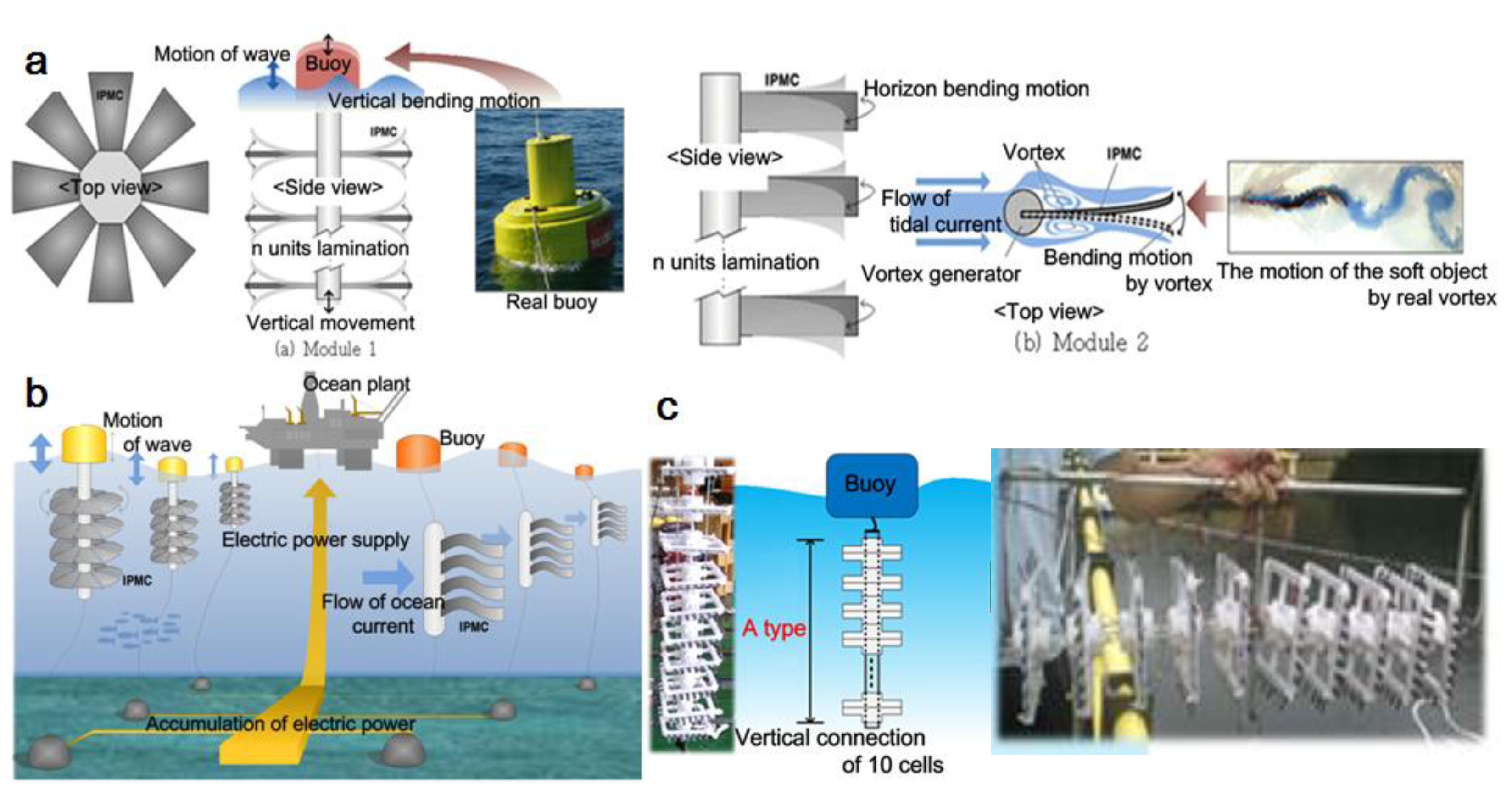
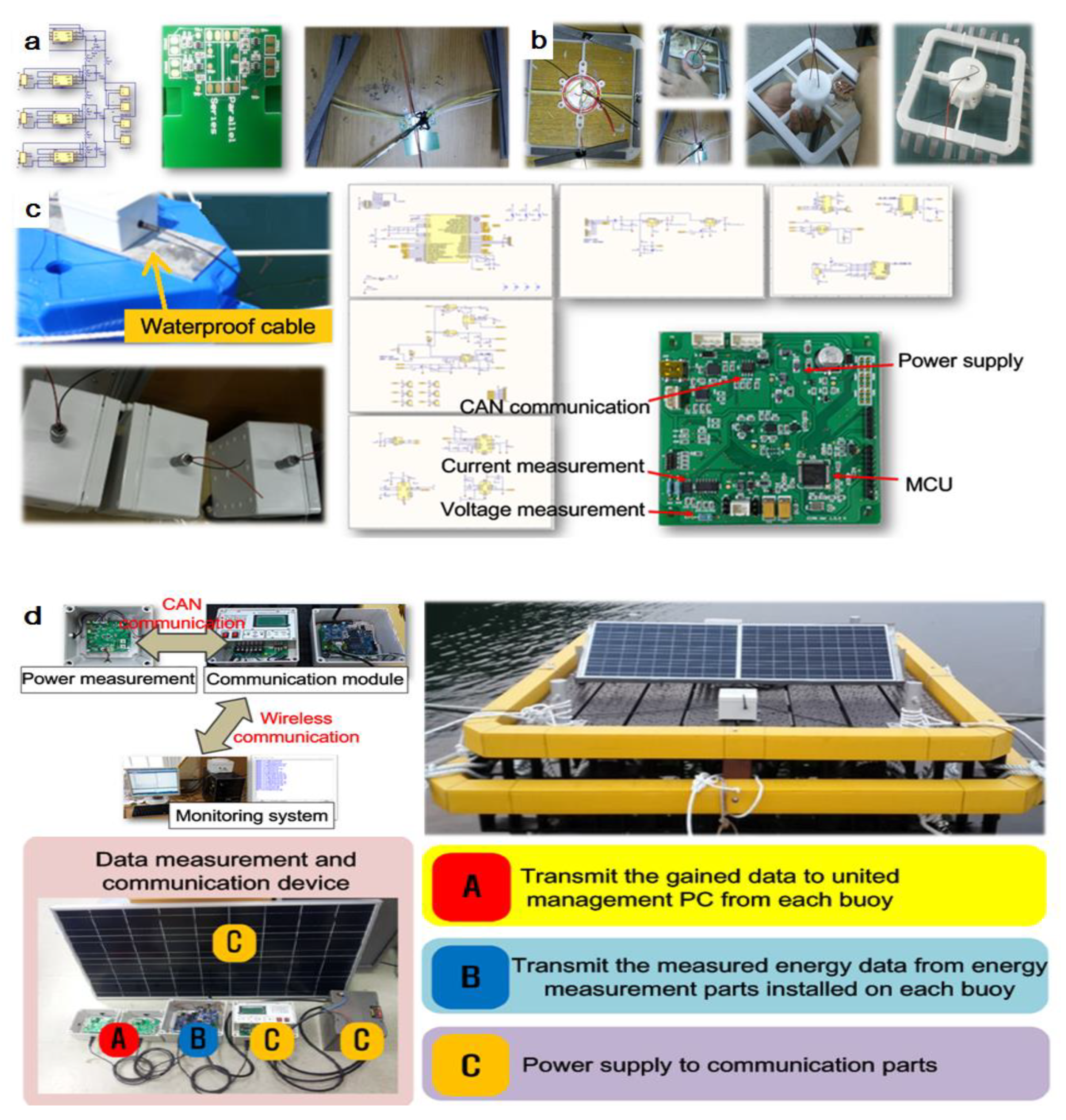
Numerical simulations of the aerodynamics, structure, and hydrodynamics of the IPMC system were conducted with hydrodynamic simulation software. The simulations were performed with the same experimental model and settings used for the concept design verification presented in previous papers [18,19]. This research optimized the design of the harvesting module equipped with IPMC materials, as shown in Figure 3. The design system was composed of 18 modules with a total of 180 cells (Figure 3c) both in the horizontal and vertical directions. Water movements are a combination of transverse and longitudinal components. Each vertical module was retrofitted with a sub-buoy to float at the water surface and ten cells. Each cell had a waterproofed rectifying electricity collector assembled in parallel to the four pairs of electrodes that clamped the IPMC sheets (Figure 4a). The entire cell was waterproof (Figure 4b). Eighteen modules were connected to the main buoy by cables. Additionally, the power and communication devices were arranged in the main buoy’s surface to collect the test data via the wireless system (Figure 4d).
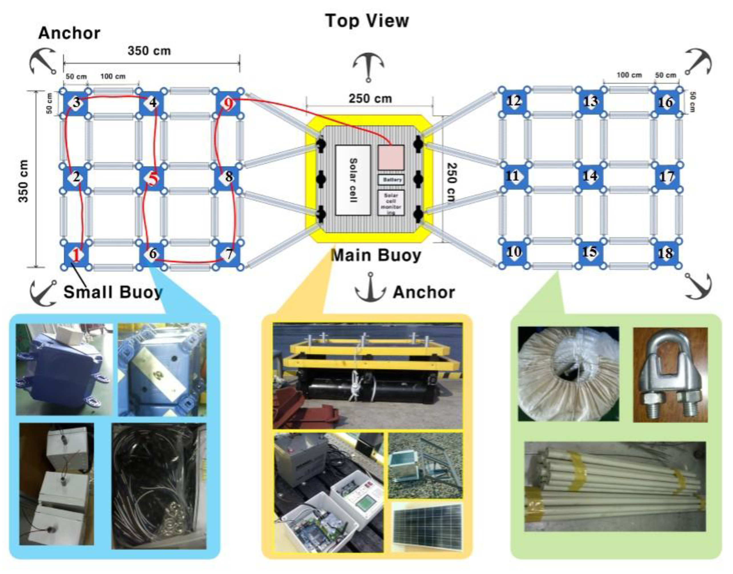
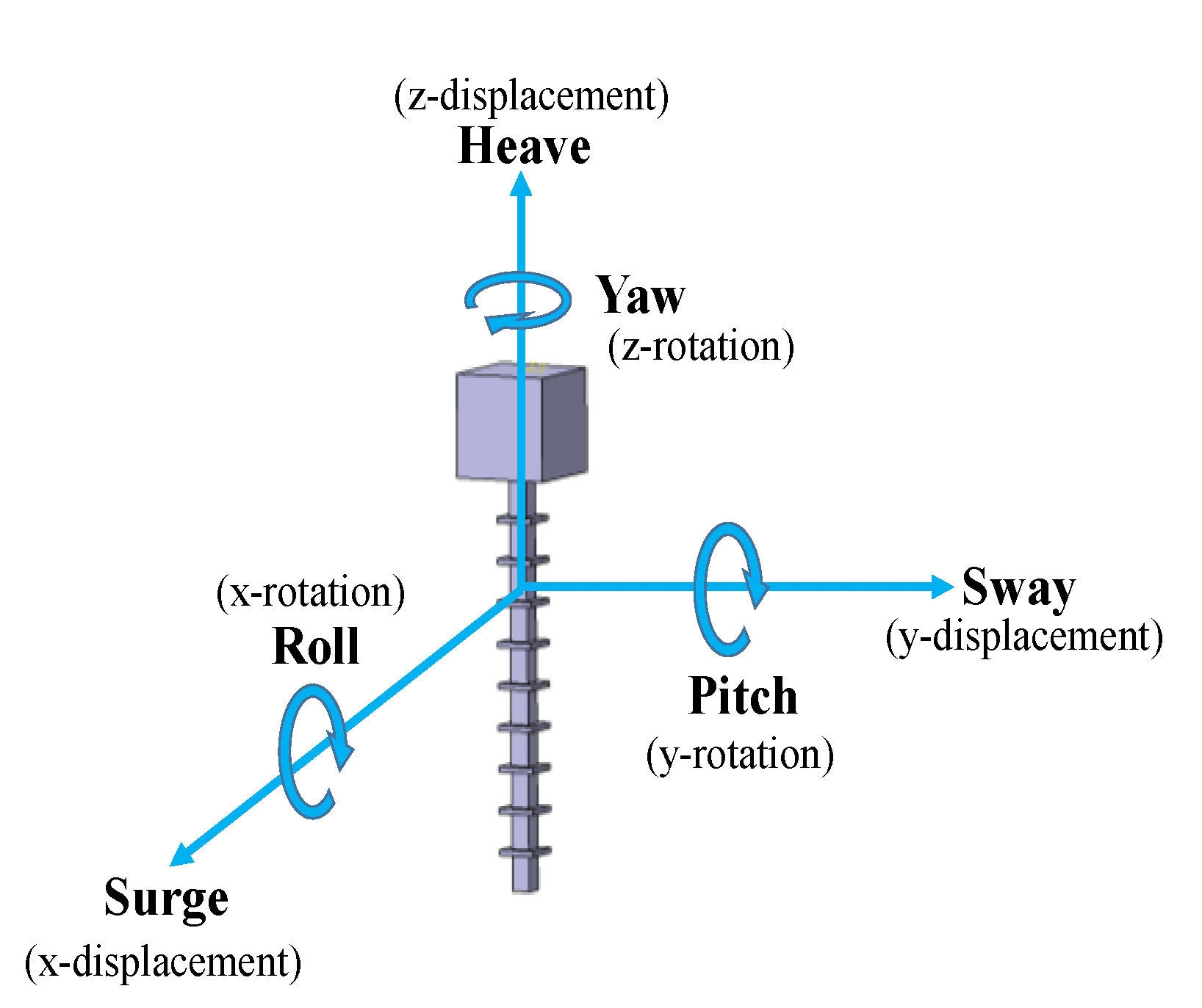
Figure 5 shows a photograph of the energy harvesting system, which was set up in the ocean and modelled with ANSYS AQWA software (Version 14.5, Canonsburg, PA, USA). However, all geometries of system simulation were created in CATIA V5R20 software ( Dassault Systèmes, Vélizy-Villacoublay, France). The part design and assembly modules in CATIA were used to establish the parts and assembly of a three-dimensional parameter model with physical and geometric characteristics. Subsequently, the solid model of the IPMC system created in the CATIA environment was imported directly into the ANSYS software to calculate the dynamic movements. Each module of the IPMC system was symmetric with respect to a vertical plane passing through its center and enclosed a body of water with a free surface. The main buoy was assumed to be stationary; meanwhile, the modules could arbitrarily move according to the wave. Moreover, IPMCs were attached to each module and changed shape when the blades were displaced. The movements of the modules and IPMCs under wave attacks were extraordinarily complicated and evaluated with response amplitude operators (RAOs). The RAOs showed the behavior of a module under wave conditions, which was calculated by solving a set of linearized equations based on the Morison equation in different directions. These equations describe the three types of displacement motions (surge, sway, heave) and three types of rotational movements (roll, pitch, and yaw), as shown in Figure 6. Consequently, the mathematical model of each module was considered as floating under the influence of the linearized hydrodynamic fluid wave loading. In this study, the fluid was considered to be ideal, incompressible, and irrotational; hence, potential flow theory was used. It was assumed that the movement and deformation of the IPMCs were directly proportional to the change of each module, which meant that the more the modules moved, the more electricity the IPMC system generated. The experimental results conducted in both the laboratory and the ocean also confirmed that the electricity performance output of the IPMCs strongly depends on the module’s movement. Therefore, this research aimed to model the displacement of the modules to identify the most suitable assembly method for the system to improve the module’s movement, thereby contributing to the performance enhancement of the electronic harvesting module. Moreover, the system stability under wave attack was also considered to avoid destruction in case of typhoons or resonant frequencies.
The numerical simulation of the IPMC system was carried out by performing frequency domain analysis with commercial software. In this research, we simulated the movement of the harvesting system corresponding to a variety of wave heights, periods, and directions based on the experiment’s collected data. The deep ocean of 5 m was selected based on the experimental data. Meanwhile, the controlled frequency data from the simulation were mentioned in [21]. Alternatively, the manual entry can be defined where the wave frequencies can be applied to either a single or multiple structure selection. Furthermore, the frequency range from 0.035 to 0.95 Hz also covered the frequency range measured from the experiments carried out at the location of the assembled IPMC system. The 3D diffraction calculations for the system interactions were also determined based on movement responses, wave fields, and deep-sea and seafloor geometry.
3. Results and Discussion
3.1. Pressure and Motion Results
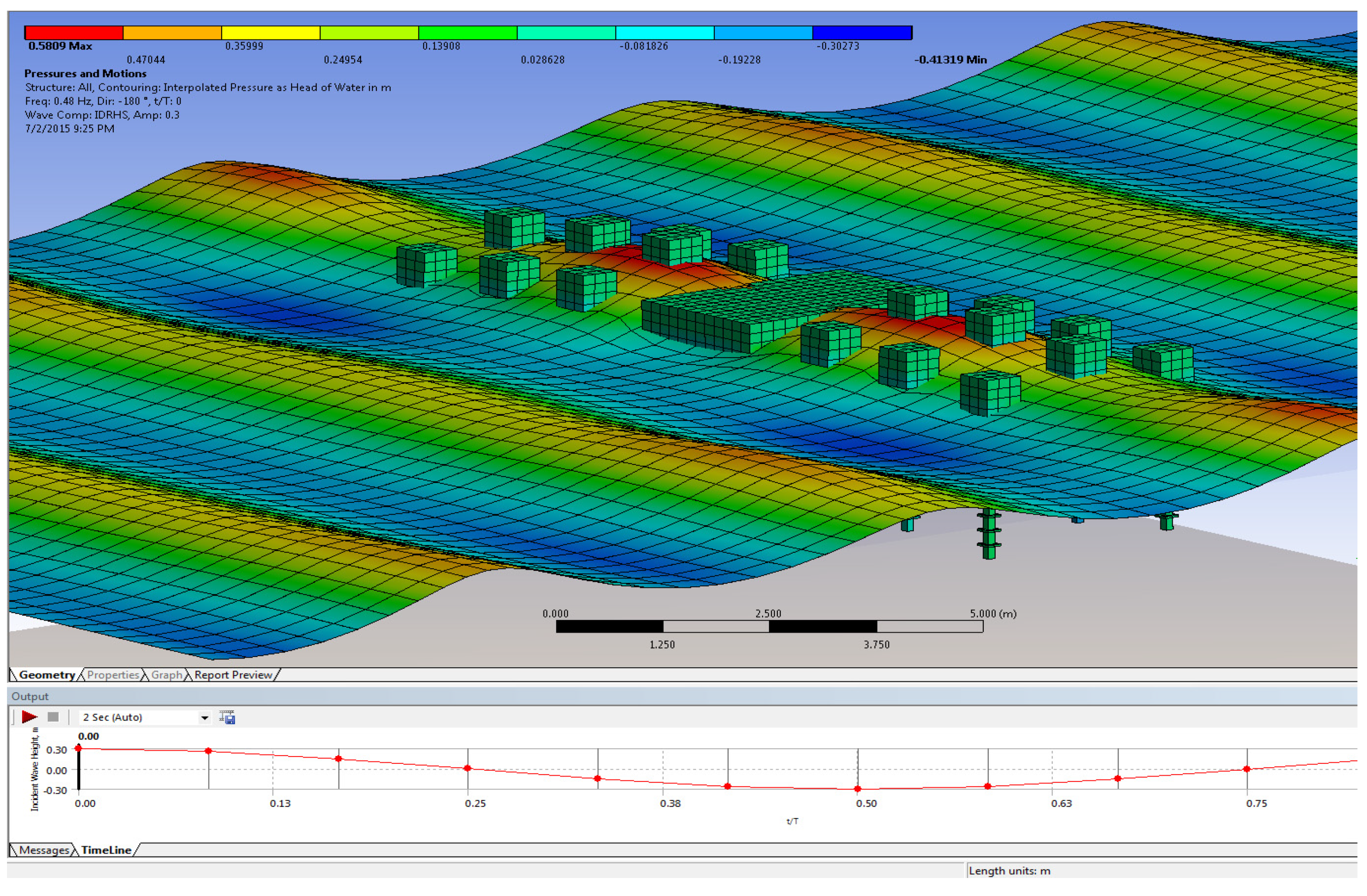
In fluid mechanics, a displacement occurs when an object is submerged in a fluid; the volume of the displaced fluid can be calculated based on the integration of the submerged surface. The hydrostatic force is calculated via the hydrostatic pressure on the wetted object surface of the body up to the still water level. With respect to the frequency domain, this research considered the small motion around the equilibrium position. Thus, the submerged area of the object is time-independent, and the hydrostatic forces and moments on the object must be computed because they cause the motion of the body in the fluid. In the simulation process, the simulated pressure and motion obtained by solving the hydrodynamic equations can be visualized and displayed. Pressure and movement may be added. As mentioned above, the results of both experimental and simulation analyses showed that the movements of the modules were directly proportional to the amplitude of the incidental wave. As a result, this paper only shows the results of the simulation corresponding to the wave amplitude of 0.3 m. Figure 7 plots the pressure and the motion of the IPMC system under wave attacks; the corresponding value of the incident wave amplitude is 0.3 m at a frequency of 0.48 Hz. All of the modules and the main buoy are attacked by waves. The main float is assumed to be fixed; meanwhile, the modules are free to move on the wave surface. The results present the movement of the blades due to incoming waves, becoming proportional to the amplitude from −0.413 m to 0.580 m.
3.2. Effect of Wave Direction and Frequency on the Movement of the Modules
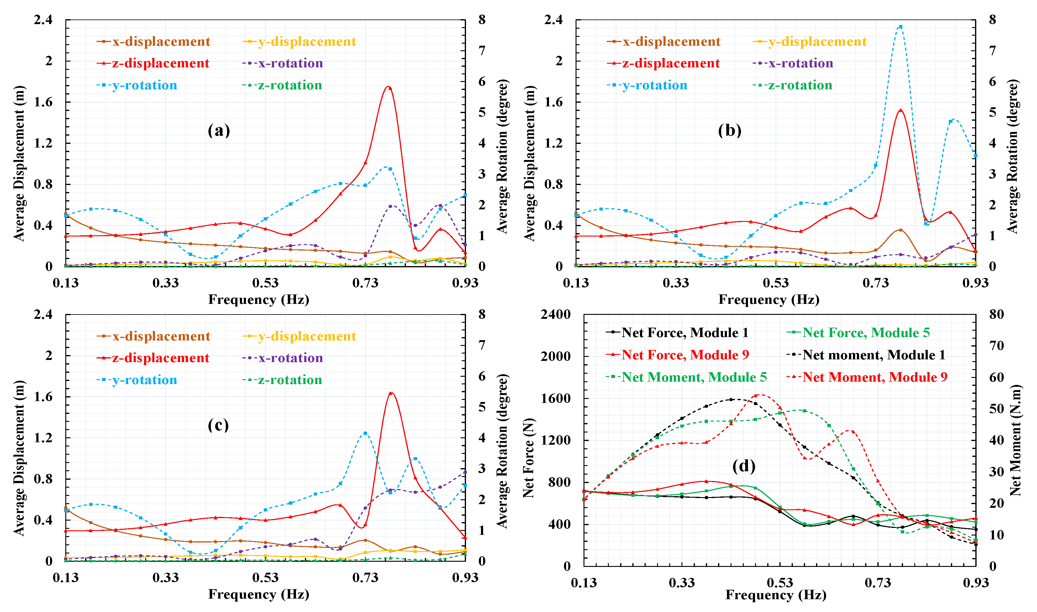
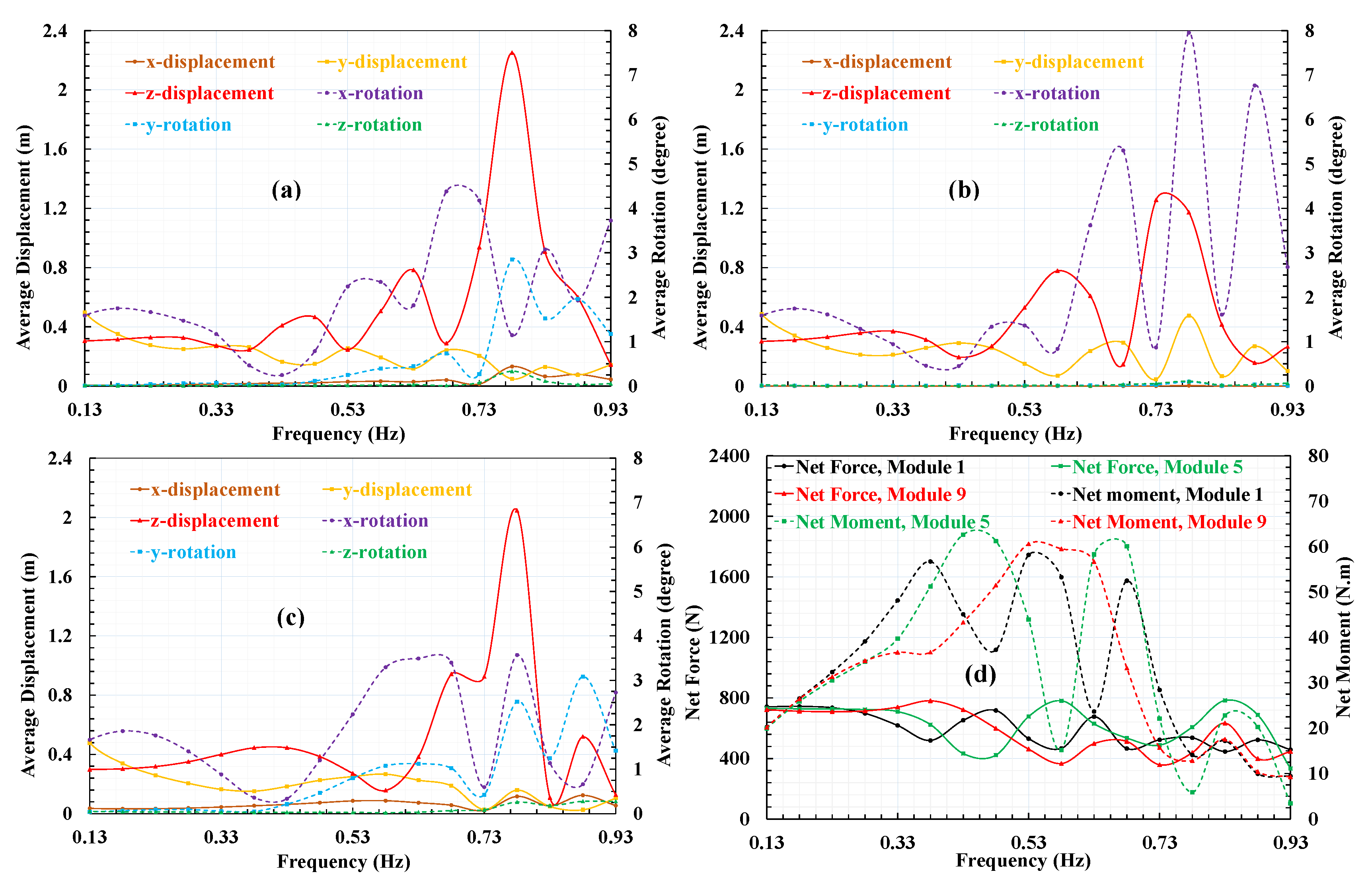
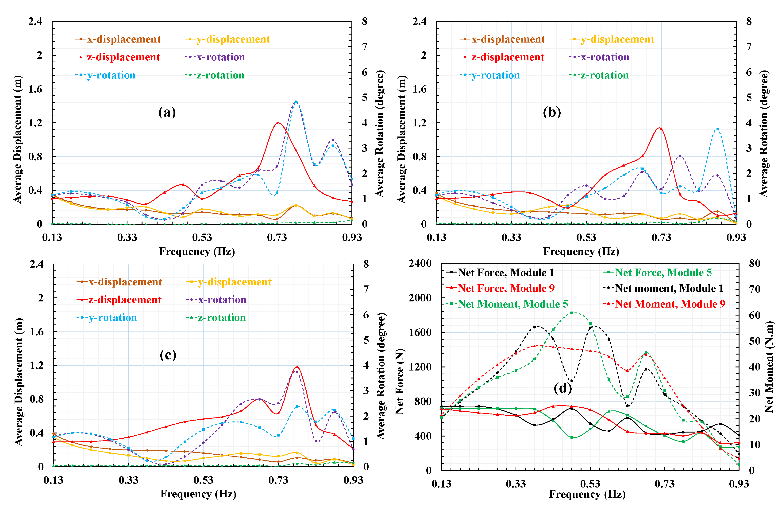
As mentioned above, the design system was composed of 18 modules; however, this paper only shows the movement of modules 1, 5, and 9 corresponding to the wave direction in the range from −180 to 180°. The movement of these modules is illustrated in Figure 8, Figure 9, Figure 10, Figure 11 and Figure 12, including the displacements and rotations of modules 1, 5, and 9 around the x-, y-, and z-axes, representing surge, sway, heave, roll, pitch, and yaw, respectively, as shown in Figure 6. The module amplitude dramatically depends on the frequencies, especially near the resonance frequency. Moreover, the incident waves result in the intense movement along the z-axis; thus, the rotation amplitudes around the z-axis are trivial at every boundary condition. The surge motion of the modules decreases as the frequency increases in almost all wave directions; however, this trend is not evident at the wave direction of 90° because this direction is perpendicular to the x-axis, resulting in a strong sway and a weak surge motion, as described in Figure 10. The movements around the x- and y-axes also change according to the amplitude. However, the maximum angle is small (about 8°); thus, the heave movement should be focused in order to improve the harvesting system performance. The object’s large movements can happen around the resonance frequencies, as described in [26]. In this case, the maximum amplitude movement of the object is about eight times compared to that of the incident wave. This phenomenon can cause the instability of the IPMC system, eventually destroying it. Thus, this phenomenon should be focused upon in order to design the structure for the targets of both high performance and stability.
The commercial software used in this research computes the hydrodynamic force on an object using three-dimensional radiation and diffraction theory. The hydrodynamic forces are composed of radiation forces and wave excitation forces. The net forces and moments of the flow acting on modules 1, 5, and 9, obtained by integrating the pressure over the wetted surfaces, are illustrated in Figure 8, Figure 9, Figure 10, Figure 11 and Figure 12. The modules also oscillate dramatically according to the frequency, direction, and amplitudes of the waves attacking each module; the maximum values of the net force and net moment on each module are 800 N and 70 Nm, respectively.
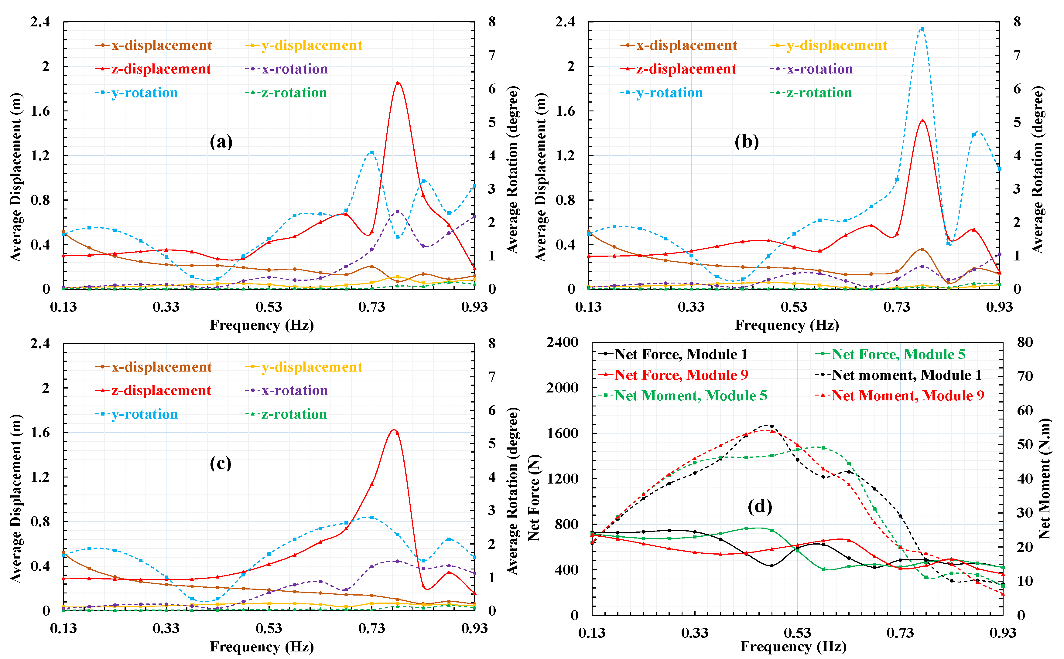
Figure 13 shows the average movements of the modules concerning the frequency at the direction of zero degrees. Generally, these movements follow the same trends as the movements of each module: the rotation movements are not remarkable; meanwhile, the z-displacement is significant and always higher than that of the ocean wave (0.3 m). The x-displacement is higher than the y-displacement, due to the number of module lines arranging accordingly in each direction and to the main buoy restricting the incident wave. The average displacement and rotation of the modules at a frequency of 0.48 Hz fluctuate approximately as harmonic functions, as illustrated in Figure 13. At 0°, −180°, and 180°, the surge, yaw, and pitch motions reach a maximum; meanwhile, the other movements are at their lowest positions. These observations suggest that the IPMC system should be placed perpendicularly to the direction of the incident waves to enhance the performance of the energy harvesting system.
3.3. Effect of the Wetted Surface Area and Mass on the Movement of the Modules
The combination of hydrodynamic forces and gravity forces can be used to calculate the small-amplitude response around an equilibrium position. The methodology utilizes a distribution of fluid singularities over the mean wetted surface of the body. Figure 13 compares the average displacement and rotation of the modules with several frequency ranges and directions, corresponding to (a) 2.13 m2, (b) 2.33 m2, and (c) 2.43 m2 of wetted surface area for each module. The wetted surface is a part of the body that is in contact with the fluid when the body is in equilibrium or a steady-state position. For equilibrium, the mass of the body must equal the mass of the displaced water, and the center of gravity and buoyancy must be along the same vertical line as no external constraining forces are being applied. This means that the mass of each module relates directly to the wetted surface; as a result, this affects the movement of the module due to the diffraction and radiation wave forces acting on the module as mentioned in previous reports ([15] and [21]). Generally, the simulated results show that the displacement of the modules is proportional to the wetted surface area at most frequencies and directions, as shown in Figure 13. However, the trend is opposite near the resonance frequency because, for a body of a given volume, the smaller wetted surface area corresponds to the lighter mass. When resonance occurs, the diffraction and radiation wave forces acting on the module increase dramatically; therefore, the module can escape the wave surface. As a result, the lighter module has a higher amplitude of movement in comparison with the more massive module. The rotation of the modules is minimal; the average magnitude of the modules in the roll, pitch, and yaw motions is only approximately 1 degree at a frequency of 0.48 Hz.
3.4. Performance Test of the Ocean Kinetic Energy Harvesting Modules
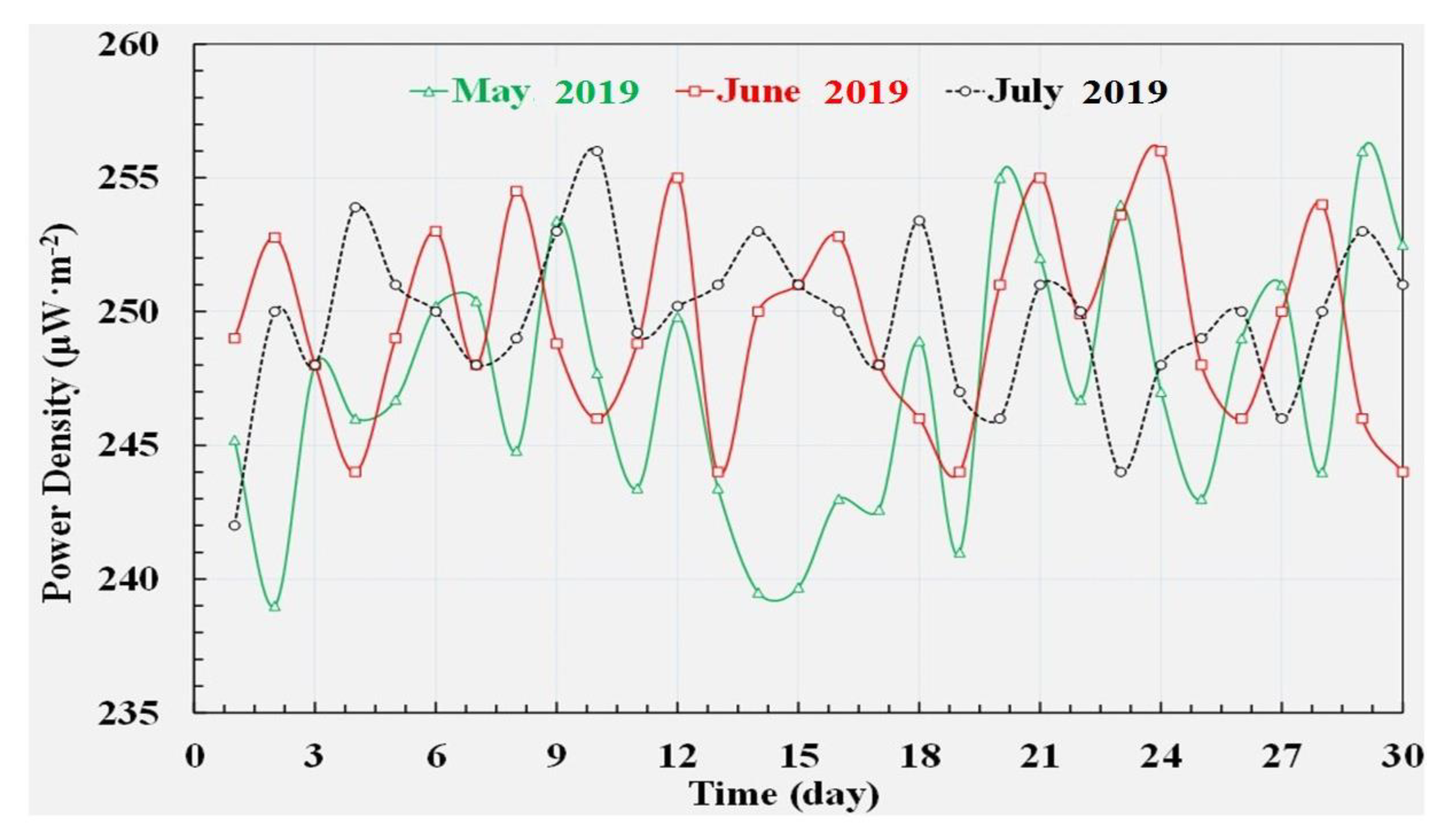
Based on the simulation results, the IPMC system was assembled not only to take full advantage of the IPMC system but also to guarantee the system stability. Consequently, the system was set perpendicularly to the wave direction. The IPMC materials were assembled around the vertical direction in such a way that these could quickly move when the parts fluctuated along the vertical direction to take full advantage of the high movement, as presented in the simulation process. The assembly of IPMCs in the module and the IPMC system are shown in Figure 3c and Figure 5, respectively. Each module includes ten layers of IPMC materials arranged in a vertical line. The ocean kinetic energy harvesting modules produced electrical energy after installation in the ocean in May 2019. The data were measured and recorded at 10 min intervals.
Figure 14 shows the extremely variable data obtained in May, June, and July 2019. During this test time, the average power density at a given time of the day sharply oscillated above 235 μW/m2 and reached a peak value of approximately 255 μW/m2. Compared with other mechanical wave energy converters that convert the energy in ocean waves into electrical power, the IPMC system seems to produce less energy; nevertheless, the IPMC material is an innovative electroactive polymer that provides electrical energy from a bending motion in a simple cantilever configuration. Furthermore, IPMC is an inexpensive and durable material; therefore, the power of the harvested energy can be advantageously improved by increasing the IPMC active area.
4. Conclusions
In this study, an energy harvesting system based on IPMC material was studied to produce electricity. The IPMC system was simulated using the computational fluid dynamics (CFD) method to evaluate the system stability and to find out the optimal setup for enhancing its energy harvesting performance. In general, the displacement of the modules was proportional to the wetted surface area at most frequencies and directions. However, the trend was opposite near the resonance frequency due to the significant increase of wave forces. The rotation of the modules was minimal; the average amplitude of the modules in the roll, pitch, and yaw motions was only approximately 1 degree. Meanwhile, the z-displacement was significantly higher than that of the other directions. Based on the simulation results, the experimental IPMC system was set perpendicular to the direction of the incident wave to take full advantage of the harvested energy. The ocean kinetic energy harvesting modules producing electrical energy have been installed in the ocean since 20 May 2019. The experimental results showed that the generated power during the three months was stable; the degradation of the IPMCs’ electrical performance over the long term of the operation is trivial. However, it is further recommended to reduce the growth of algae and barnacles on the modules to maintain high efficiency in generating electricity. Therefore, every module should be covered with a protective layer to prevent the penetration of algae and barnacles in order to preserve the IPMCs’ electrical performance.
In conclusion, the development of ocean kinetic energy harvesting systems with a conductive graphene-based solution of IPMC presented many advantages compared with those of mechanical wave energy converters for generating electric power from ocean kinetic energy because IPMC is an inexpensive and durable material that quickly generates electricity. However, the implementation from the initial concept to the commercial manufacturing stage has been a challenging, slow, and expensive process. More work is required for a thorough evaluation of abnormal phenomena such as resonance or the disruption of electrical energy harvesting due to the growth of algae and barnacles on the module, which affected the bending motion of the IPMC. Moreover, the specific power produced by the IPMC system is still small in comparison with that of other devices; as a result, it is necessary to identify solutions to enhance its performance.
Future research will focus on examining the system stability under extreme conditions, including unusual, severe, or unseasonal weather. In addition, we will also investigate and measure the IPMC material properties to study their movements and electrical characteristics. Furthermore, the entire process of changes in the complex IPMC system and the effect of wave amplitude on its movements will be physically modelled and validated by using the experimental results.
Author Contributions
V.N.D. and H.-M.K. conducted the simulation, fieldwork was carried out by V.N.D., and H.-M.K. performed empirical analyses. V.N.D. and H.-M.K. contributed to the writing of the manuscript. All authors have read and agreed to the published version of the manuscript.
Funding
This work was supported partly by Basic Science Research Program (No. 2015R1D1A1A02060006) and partly by Korea-Canada Cooperative Development Program (No. 2018K1A3A1A74064262) funded by the National Research Foundation of Korea (NRF).
Conflicts of Interest
The authors declare no conflict of interest.
References
- Lejerskog, E.; Boström, C.; Hai, L.; Waters, R.; Leijon, M. Experimental results on power absorption from a wave energy converter at the Lysekil wave energy research site. Renew. Energy 2015, 77, 9–14. [Google Scholar]
- Salter, S.H. World progress in wave energy—1988. Int. J. Ambient Energy 1989, 10, 3–24. [Google Scholar] [CrossRef]
- Teillant, B.; Costello, R.; Weber, J.; Ringwood, J. Productivity and economic assessment of wave energy projects through operational simulations. Renew. Energy 2012, 48, 220–230. [Google Scholar] [CrossRef] [Green Version]
- Nunes, G.; Valério, D.; Beirão, P.; Sá da Costa, J. Modelling and control of a wave energy converter. Renew. Energy 2011, 36, 1913–1921. [Google Scholar] [CrossRef]
- Valério, D.; Beirão, P.; Sá da Costa, J. Optimisation of wave energy extraction with the Archimedes Wave Swing. Ocean. Eng. 2007, 34, 2330–2344. [Google Scholar] [CrossRef]
- Martinelli, L.; Zanuttigh, B.; Kofoed, J.P. Selection of design power of wave energy converters based on wave basin experiments. Renew. Energy 2011, 36, 3124–3132. [Google Scholar] [CrossRef]
- Sheng, W.; Alcorn, R.; Lewis, T. Physical modelling of wave energy converters. Ocean. Eng. 2014, 84, 29–36. [Google Scholar] [CrossRef]
- Babajani, A.; Jafari, M.; Hafezisefat, P.; Mirhosseini, M.; Rezania, A.; Rosendahl, L. Parametric study of a wave energy converter (Searaser) for Caspian Sea. Energy Procedia 2018, 147, 334–342. [Google Scholar] [CrossRef]
- Hals, J.; Falnes, J.; Moan, T. A comparison of selected strategies for adaptive control of wave energy converters. J. Offshore Mech. Arct. Eng. 2011, 133. [Google Scholar] [CrossRef]
- Uihlein, A.; Magagna, D. Wave and tidal current energy—A review of the current state of research beyond technology. Renew. Sustain. Energy Rev. 2016, 58, 1070–1081. [Google Scholar] [CrossRef]
- Kolios, A.; Di Maio, L.F.; Wang, L.; Cui, L.; Sheng, Q. Reliability assessment of point-absorber wave energy converters. Ocean. Eng. 2018, 163, 40–50. [Google Scholar] [CrossRef]
- Yamaç, H.İ.; Koca, A. Numerical analysis of wave energy converting systems in case of using piezoelectric materials for energy harvesting. J. Mar. Eng. Technol. 2018, 4177. [Google Scholar] [CrossRef]
- Chow, Y.C.; Chang, Y.C.; Lin, C.C.; Chen, J.H.; Tzang, S.Y. Experimental investigations on wave energy capture of two bottom-hinged-flap WECs operating in tandem. Ocean. Eng. 2018, 164, 322–331. [Google Scholar] [CrossRef]
- Zhang, X.; Lu, D.; Guo, F.; Gao, Y.; Sun, Y. The maximum wave energy conversion by two interconnected floaters: Effects of structural flexibility. Appl. Ocean. Res. 2018, 71, 34–47. [Google Scholar] [CrossRef]
- Zheng, S.M.; Zhang, Y.H.; Zhang, Y.L.; Sheng, W.A. Numerical study on the dynamics of a two-raft wave energy conversion device. J. Fluids Struct. 2015, 58, 271–290. [Google Scholar] [CrossRef]
- Khojasteh, D.; Kamali, R. Evaluation of wave energy absorption by heaving point absorbers at various hot spots in Iran seas. Energy 2016, 109, 629–640. [Google Scholar] [CrossRef]
- Eriksson, M.; Isberg, J.; Leijon, M. Hydrodynamic modelling of a direct drive wave energy converter. Int. J. Eng. Sci. 2005, 43, 1377–1387. [Google Scholar] [CrossRef]
- Park, S.; Ahn, J.; Lee, J.; Park, S.; Kim, H.M.; Park, K.; Hwang, G.; Kim, M.; Baek, S.; Byun, G.S. An ionic polymer metal composite based electrochemical conversion system in the ocean. Int. J. Electrochem. Sci. 2014, 9, 8067–8078. [Google Scholar]
- Vinh, N.D.; Kim, H.-M. Ocean-based electricity generating system utilizing the electrochemical conversion of wave energy by ionic polymer-metal composites. Electrochem. Commun. 2017, 75. [Google Scholar] [CrossRef]
- Oh, C.; Kim, S.; Kim, H.; Park, G.; Kim, J.; Ryu, J.; Li, P.; Lee, S.; No, K.; Hong, S.; et al. Effects of membrane thickness on the performance of ionic polymer–metal composite actuators. RSC Advances 2019, 14621–14626. [Google Scholar] [CrossRef] [Green Version]
- Li, D.J.; Hong, S.; Heinonen, O. Polymer piezoelectric energy harvesters for low wind speed. Appl. Phys. Lett. 2013, 1–6. [Google Scholar] [CrossRef]
- Kwaśniewski, J.; Dominik, I.; Kaszuba, F. Energy Harvesting System Based on Ionic. Pol. J. Environ. Stud. 2014, 23, 2339–2343. [Google Scholar]
- Cha, Y.; Shen, L.; Porfiri, M. Energy harvesting from underwater torsional vibrations of a patterned ionic polymer metal composite. Smart Mater. Struct. 2013, 22. [Google Scholar] [CrossRef]
- Koo, W.; Kim, J. Simplified formulas of heave added mass coefficients at high frequency for various two-dimensional bodies in a finite water depth. Int. J. Nav. Arch.. Ocean. Eng. 2015, 7, 115–127. [Google Scholar] [CrossRef] [Green Version]
- Söylemez, M. A general method for calculating hydrodynamic forces. Ocean. Eng. 1996, 23, 423–445. [Google Scholar] [CrossRef]
- Zheng, Y.H.; Shen, Y.M.; Tang, J. Radiation and diffraction of linear water waves by an infinitely long submerged rectangular structure parallel to a vertical wall. Ocean. Eng. 2007, 34, 69–82. [Google Scholar] [CrossRef]
Figure 1.
Electricity generation of ionic polymer–metal composites (IPMCs) under force impact.

Figure 2.
Circuit model of the IPMC material.

Figure 3.
Experimental design of the IPMC system: (a) the fundamental design, (b) the system assembly in the ocean, and (c) the module assembly.
Figure 3.
Experimental design of the IPMC system: (a) the fundamental design, (b) the system assembly in the ocean, and (c) the module assembly.

Figure 4.
Harvesting energy module: (a) rectifying electricity collector connected in parallel to four IPMC-covered electrodes inside a cell, (b) total process of fabrication and assembly for a cell, (c) the connecting device, and (d) the main buoy and the components of an electricity collector.
Figure 4.
Harvesting energy module: (a) rectifying electricity collector connected in parallel to four IPMC-covered electrodes inside a cell, (b) total process of fabrication and assembly for a cell, (c) the connecting device, and (d) the main buoy and the components of an electricity collector.

Figure 5.
The IPMC system including a main buoy and modules used for the simulation and the experiment.
Figure 5.
The IPMC system including a main buoy and modules used for the simulation and the experiment.

Figure 6.
The six degrees of freedom of the displacement modules at the free surface of the wave.

Figure 7.
Water pressures and wave motion around the IPMC system installed in the ocean.

Figure 8.
Average displacement of (a) module 1, (b) module 5, (c) module 9, and (d) net forces and moments corresponding to 0° of the wave direction.
Figure 8.
Average displacement of (a) module 1, (b) module 5, (c) module 9, and (d) net forces and moments corresponding to 0° of the wave direction.

Figure 9.
Average displacement of (a) module 1, (b) module 5, (c) module 9, and (d) net forces and moments corresponding to 45° of the wave direction.
Figure 9.
Average displacement of (a) module 1, (b) module 5, (c) module 9, and (d) net forces and moments corresponding to 45° of the wave direction.

Figure 10.
Average displacement of (a) module 1, (b) module 5, (c) module 9, and (d) net forces and moments corresponding to 90° of the wave direction.
Figure 10.
Average displacement of (a) module 1, (b) module 5, (c) module 9, and (d) net forces and moments corresponding to 90° of the wave direction.

Figure 11.
Average displacement of (a) module 1, (b) module 5, (c) module 9, and (d) net forces and moments corresponding to 135° of the wave direction.
Figure 11.
Average displacement of (a) module 1, (b) module 5, (c) module 9, and (d) net forces and moments corresponding to 135° of the wave direction.

Figure 12.
Average displacement of (a) module 1, (b) module 5, (c) module 9, and (d) net forces and moments corresponding to 180° of the wave direction.
Figure 12.
Average displacement of (a) module 1, (b) module 5, (c) module 9, and (d) net forces and moments corresponding to 180° of the wave direction.

Figure 13.
Average displacement and rotation of 18 modules with a variety of frequency ranges and directions, (a) 2.13 m2, (b) 2.33 m2, and (c) 2.43 m2 of wetted surface area for each module.
Figure 13.
Average displacement and rotation of 18 modules with a variety of frequency ranges and directions, (a) 2.13 m2, (b) 2.33 m2, and (c) 2.43 m2 of wetted surface area for each module.

Figure 14.
The power density of the energy harvesting system for three months.

© 2020 by the authors. Licensee MDPI, Basel, Switzerland. This article is an open access article distributed under the terms and conditions of the Creative Commons Attribution (CC BY) license (http://creativecommons.org/licenses/by/4.0/).
Share and Cite
MDPI and ACS Style
Nguyen Duy, V.; Kim, H.-M. A Study of the Movement, Structural Stability, and Electrical Performance for Harvesting Ocean Kinetic Energy Based on IPMC Material. Processes 2020, 8, 641. https://doi.org/10.3390/pr8060641
AMA Style
Nguyen Duy V, Kim H-M. A Study of the Movement, Structural Stability, and Electrical Performance for Harvesting Ocean Kinetic Energy Based on IPMC Material. Processes. 2020; 8(6):641. https://doi.org/10.3390/pr8060641
Chicago/Turabian StyleNguyen Duy, Vinh, and Hyung-Man Kim. 2020. "A Study of the Movement, Structural Stability, and Electrical Performance for Harvesting Ocean Kinetic Energy Based on IPMC Material" Processes 8, no. 6: 641. https://doi.org/10.3390/pr8060641
Note that from the first issue of 2016, this journal uses article numbers instead of page numbers. See further details here.