Prediction of the Side Drift Force of Full Ships Advancing in Waves at Low Speeds


1
School of Mechanical and Aerospace Engineering, Nanyang Technological University, 50 Nanyang Ave., Singapore 639798, Singapore
2
Ship Design Laboratory, National Technical University of Athens, 9 Heroon Polytechniou, 15773 Athens, Greece
3
Hamburger Schiffbau-Versuchsanstalt, 164 Bramfelder Str., 22305 Hamburg, Germany
*
Author to whom correspondence should be addressed.
J. Mar. Sci. Eng. 2020, 8(5), 377; https://doi.org/10.3390/jmse8050377
Submission received: 3 May 2020
/
Revised: 21 May 2020
/
Accepted: 21 May 2020
/
Published: 25 May 2020
(This article belongs to the Special Issue Ship Dynamics for Performance Based Design and Risk Averse Operations)
Abstract
:In this study, we analyze the experimental results of the mean sway (side drift) forces of six full type ships at low speeds in regular waves of various directions and compare them with numerical results of the in-house 3D panel code NEWDRIFT. It is noted that the mean sway force is most significant in relatively short waves, with the peak being observed at λ/LPP ≈ 0.5–0.6. For λ/LPP > 1.0, the corresponding value is rather small. We also observe a solid recurring pattern of the mean sway force acting on the analyzed full type ships. On this basis, we proceed to approximate the mean sway force with an empirical formula, in which only the main ship particulars and wave parameters are used. Preliminary validation results show that the developed empirical formula, which is readily applicable in practice, can accurately predict the mean sway force acting on a full ship, at both zero and non-zero speeds.
1. Introduction
The prediction of the second order steady wave forces and moment of a ship or a floating structure in waves is a classical ship dynamic problem. The longitudinal component in the direction of a ship’s forward speed (added resistance) is of major concern when discussing ship’s speed-power performance in realistic seaways, while the transverse and rotational components significantly affect the maneuvering performance of a ship, hence, they are directly related to the safe navigation of the ship in a seaway.
Several theoretical approaches of varying complexity and accuracy have been developed and validated since the early 1940s, when Havelock [1] developed the first theoretical approach to calculate the steady drift force acting on a fixed vertical circular cylinder in waves. Besides a few analytical approaches to the drift forces acting on analytically defined forms, the current well established numerical methods can be classified into two main categories, namely, the far-field and near-field, pressure methods. The far-field methods are based on energy considerations for the diffracted (reflected and transmitted) and radiated wave, the momentum flux at infinity and the work done on the body in the near-field, leading to the acting steady force by the total rate of momentum change. The near-field methods, on the other side, calculate the steady second order forces/moments by direct integration of the hydrodynamic, steady second order pressure acting on the wetted body surface. This pressure can be calculated exactly from first order potential functions and their derivatives, thus, there is no need to solve the exact second order potential theory problem.
In the frame of potential flow theory, the far-field approach was introduced by Maruo [2] leading to the calculation of the steady second order longitudinal forces and then extended by Newman [3] to calculate the steady second order yaw moment as well. Salvesen [4] investigated the added resistance problem by applying the radiated energy approach of Gerritsma and Beukelman [5], which is in line with Maruo’s theory, but while using the basic potential flow solution of the Salvesen–Tuck–Faltinsen (STF) seakeeping strip theory [6]; they obtained satisfactory results for the investigated ship hull forms. Following also the far-field approach, Mavrakos [7] presented a solution to the vertical second order forces and pitch moment acting on floating axisymmetric bodies. Finally, Kashiwagi [8] presented results for the second order steady forces based on the far-field method but using a more consistent numerical seakeeping method accounting for 3D effects.
The near-field, direct pressure integration method has been practically developed in parallel with the far-field method. Boese [9] proposed a first pressure integration method, though the associated hydrodynamic pressure distribution was very simplified. More exact 3D formulations and numerical implementations were introduced in the later years, first dealing with the zero speed second order problem [10,11,12,13,14] with good validation results. It was proven that both far- and near-field methods lead to the same results, even though numerical implementations may justify minor differences [15,16].
An important issue in both methods is the treatment of the forward speed effect in the calculation of the ensuing first order potential function and its derivatives. For slender, ship-like forms, slender body theory may be applied for the forward speed effect. It can be shown that this simplification is also well applicable to non-slender ships (full type ships) at low speed of advance [17]. A negative side effect of this approximation is, however, that the steady wave formation at a ship’s bow region is not properly accounted for. This is problematic when applying the near-field pressure integration method, because of the dominance of the so-called line integral term. Joncquez [18] further developed the near-field method by including an improved formulation for the steady pressure and the results improved, even though it still shows discrepancy from experimental data in short waves.
In the validation of both methods, the focus has been mainly on the longitudinal component, which is also known as added resistance, as it affects significantly the speed-power performance (and then, the associated fuel and emission performances) of a ship in seaways. Therefore, many studies were devoted to the improvement of various issues in the implementation of such methods, as documented in, but not limited to, the works of Chen [19], Duan & Li [20], Liu et al. [21], Ohkusu [22], Sakamoto and Baba [23], Tsujimoto et al. [24], and Yang et al. [25], etc.
The other force and moment components, such as the steady sway force and yaw moment, mainly influence the design of mooring systems of floating structures (zero speed problem) and the maneuvering performance of ships in waves. Experimental measurements for the validation of numerical methods have to be carried out in ocean basins and the model size is trivially constrained by the size of the basin, hence, it is usually relatively small for the demand of the accurate validation measurements of the concerned second order quantities. For this reason, rather limited results have been reported to the public and the validation of various methods on predicting these components has been much less intensive, as indicated in various studies (for instance, in Skejic & Faltinsen [26]). Nevertheless, over the years, some experimental data of standard designs as well as several standard hull forms have been gradually released to the public. For VLCC tanker designs, Naito et al. [27] reported the experimental steady forces and moment acting on the Esso Osaka ship at low speeds using a 4.0 m long model. Iwashita et al. [28] published the experimental data of a VLCC model advancing in oblique waves using a 3.14 m long model. Ueno et al. [29] studied the steady wave forces and moment of a VLCC tanker in short waves at zero and small forward speed. Ueno et al. [30] measured the steady forces and moment of a VLCC tanker at zero speed in waves of various lengths and headings. Within the framework of the EU funded SHOPERA project [31], the steady forces and yaw moment of the benchmark ship KVLCC2 in steep waves at zero speed were measured using a 4 m model [32]; the same ship was the subject of an international benchmark study on contemporary numerical methods [33]. For bulk carrier designs, Kadomatsu et al. [34] published the experimental results of a capesize bulker design using a 2.91 m long model. Yasukawa et al. [35] reported to the public the steady wave forces and yaw moment of the S-Cb84 model at several speeds.
The experimental data accumulated in the public domain over the years make nowadays a qualitative, and to some extent, quantitative validation of numerical methods possible, namely comparing the numerical results generated by a numerical method and software for a specific design and examine the results against available experimental data of the same or similar hull forms. In the present study, the well-established frequency domain 3D boundary element method and associated computer code NEWDRIFT [12,14,17,36] is used to solve the basic seakeeping problem and to calculate the second order steady sway force. Furthermore, we proceeded to approximate the mean sway force with an empirical formula, in which only the main ship particulars and wave parameters are used. Applications to standard ship designs were carried out to validate the applicability and the accuracy of the developed and implemented methods in practice and to make recommendations on the way ahead.
2. Background of the Employed 3D Panel Method
We consider a ship advancing at constant mean forward speed U in regular sinusoidal waves of small amplitude. The ship’s heading is defined by angle α measured between the direction of U and the direction of wave propagation (α = 0° represents following waves). The wave frequency ω0 is related to the ship’s frequency of encounter ω by
where wave number k = 2π/λ, and with λ being the wavelength.
The resulting oscillatory motions of the ship are assumed linear and harmonic. An orthogonal coordinate system Oxyz is assumed at the mean position of the ship, with positive z-axis vertically upwards through the center of gravity of the ship, positive x-axis towards the ship’s bow, and O in the plane of undisturbed free surface. The ship is assumed to oscillate as a rigid body in six degrees of freedom with amplitudes ηi, where i = 1, 2, …, 6 refer to surge, sway, heave, roll, pitch and yaw motions, respectively. The six linear coupled differential equations of motions are:
where are components of the generalized mass matrix of the ship, and are added mass and damping coefficients, are hydrostatic restoring force coefficients, are the complex amplitudes of wave exciting forces and moments, and j is the imaginary unit associated with a harmonic time function. Only the real part is taken in all expressions involving .
Assuming potential flow, the velocity potential is separated into a time-independent steady part due to ship’s speed U and time-dependent part associated with the incident wave and the excited unsteady oscillatory motions, which are assumed small in response to small amplitude incident waves:
Here, is the steady part and the complex amplitude of the unsteady potential part. We assume that the operator , appearing in the free surface boundary condition of the ensuing BVP for Φ, is small, which holds for
- U small (low speed),
- ω large (high wave frequency/short waves) and/or
- small, which holds for slender bodies.
Under these conditions, the problem is linearized by disregarding higher order terms in and and terms containing their cross products. The steady and unsteady velocity potentials can be determined separately. is then decomposed as follows:
where is the incident wave potential, the diffracted wave potential, and the velocity potential for the i-th mode of motion. All , i = 0, ..., 7 satisfy Laplace’s equation in the fluid domain and appropriate boundary conditions at the wetted surface, the free surface and at infinity.
We introduce the zero speed Green’s function G(p, q) representing the potential at a field point p(z, y, z) of a pulsating source of unit strength at point q(ξ, η, ζ). Applying Green’s 3rd theorem to the harmonic functions G(p, q) and , a set of Fredholm integral-equations is derived, to be solved for the complex source strengths, based on which the potential values can be obtained.
Having obtained , the hydrodynamic pressure p due to the unsteady velocity potential can be calculated by Bernoulli’s equation:
Integrating the pressure over the wetted hull surface yields the hydrodynamic forces and moments, which finally lead to the values of the hydrodynamic coefficients in the equations of motion (2), namely , and . These coefficients are corrected for the effect of forward speed on the basis of expressions derived from the slender body theory [17]. Thus, the six DOF equations of motions can be set up and solved for the motions of the ship.
Both the far-field method and near-field (pressure integration) method have been implemented in the code NEWDRIFT to calculate the quasi second order forces/moments [12,37]. The classic near-field (pressure integration) method for the calculation of the transverse steady second order force at low speed of advance has the following form:
where is the first order relative wave height along the ship waterline and is the ship motion amplitude in i-th direction, is the total velocity potential, M is the mass of the ship, and the z-coordinate of the center of gravitation of the ship, and is the sectional flare angle (0 means vertical wall) at the ship’s SWL waterline.
3. Subject Models
Table 1 presents the main particulars, associated hull coefficients and ratios, and testing conditions of six full ships that are used in the present analysis. The associated experimental results are available for Froude numbers Fr between 0.0 and 0.10, which correspond to low and up to moderate speeds and are typical conditions in ship maneuvering. Four sets of the experimental data are obtained in free motion conditions, while the data for VLCCa and Esso Osaka are in motion restrained conditions. All of these experimental data are in the public domain and the references for each set of data are given.
Regarding the available information of the hull forms, the lines of the KVLCC2, S-Cb84, the bulk carrier and the Esso Osaka are available in the public domain, while that of the VLCCa and VLCCb are not. For VLCCa, the block coefficient is the same as KVLCC2, while the L/T is close to that of KVLCC2, and the L/B smaller and B/T larger. These characteristics give us good reason to apply a simple affine distortion method to the KVLCC2 offsets to generate an approximate lines plan [38]. The scaling factors for the three axes in this simple affine distortion are as follows:
α1 = 3.100/320.0 = 0.00969; β1 = 0.610/58.0= 0.01052; γ1 = 0.200/20.8 = 0.00962
For VLCCb, a similar procedure is applied to generate her hull form from KVLCC2’s lines:
α2 = 2.970/320.0 = 0.00928; β2 = 0.538/58.0 = 0.00928; γ2 = 0.179/20.8 = 0.00861
The predicted mean second order force for the two approximated hull forms will be denoted as VLCCa’ and VLCCb’, respectively.
4. Numerical Results and Discussion
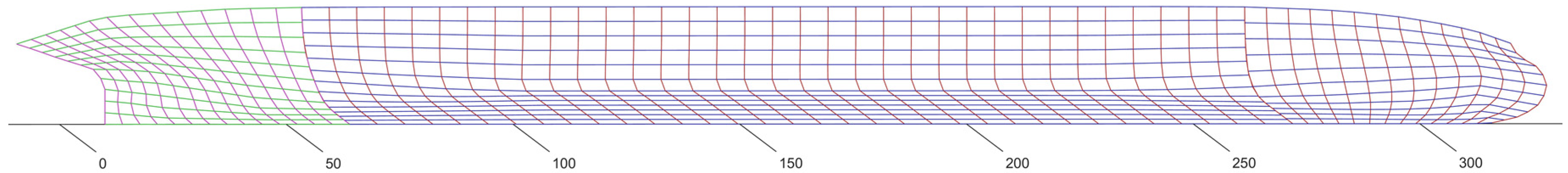
Figure 1 shows the used panelization of the wetted part of the hull form of S-Cb84 model, with 739 panels for half of the ship’s surface. Similar panelizations have been applied to all the investigated ship models.
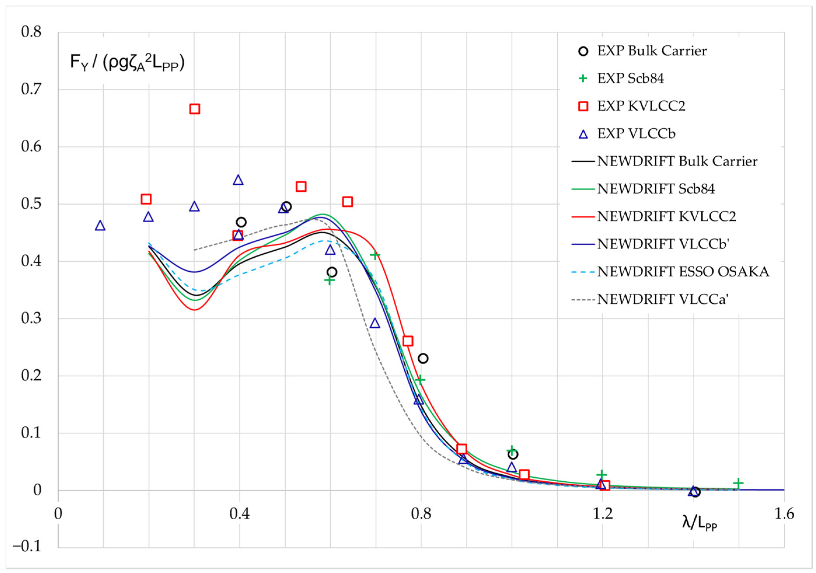
Figure 2 shows the calculated mean sway forces of the six ships in beam waves at zero speed as obtained both from experiments and from numerical predictions using NEWDRIFT. Overall, it is noted that the four sets of experimental results are close to each other, except for the results of KVLCC2, which show some oscillatory behavior in short waves. This might be due to the fact that the generated waves in this region were quite steep for KVLCC2. Note, also, that the model length of the KVLCC2 was the largest among the six test ships. The obtained numerical results show a similar trend for the mean sway force of the six ships. The maximum non-dimensional mean sway force is observed at λ/LPP ≈ 0.5–0.7. In short waves, the non-dimensional values all tend to approach a certain value between 0.4–0.5, which is expected, when considering that the limiting value of the mean sway force on a vertical wall is 0.5. The limiting value is a bit less than 0.5 because the hull is not vertical near the waterline, particularly at both ends. Nevertheless, some increased uncertainty appears in very short waves. This can be due to experimental and numerical issues. On the numerical side, in short waves, very small panels are needed and in addition, the phenomenon of irregular frequencies may trigger oscillations in the obtained results [19,39].
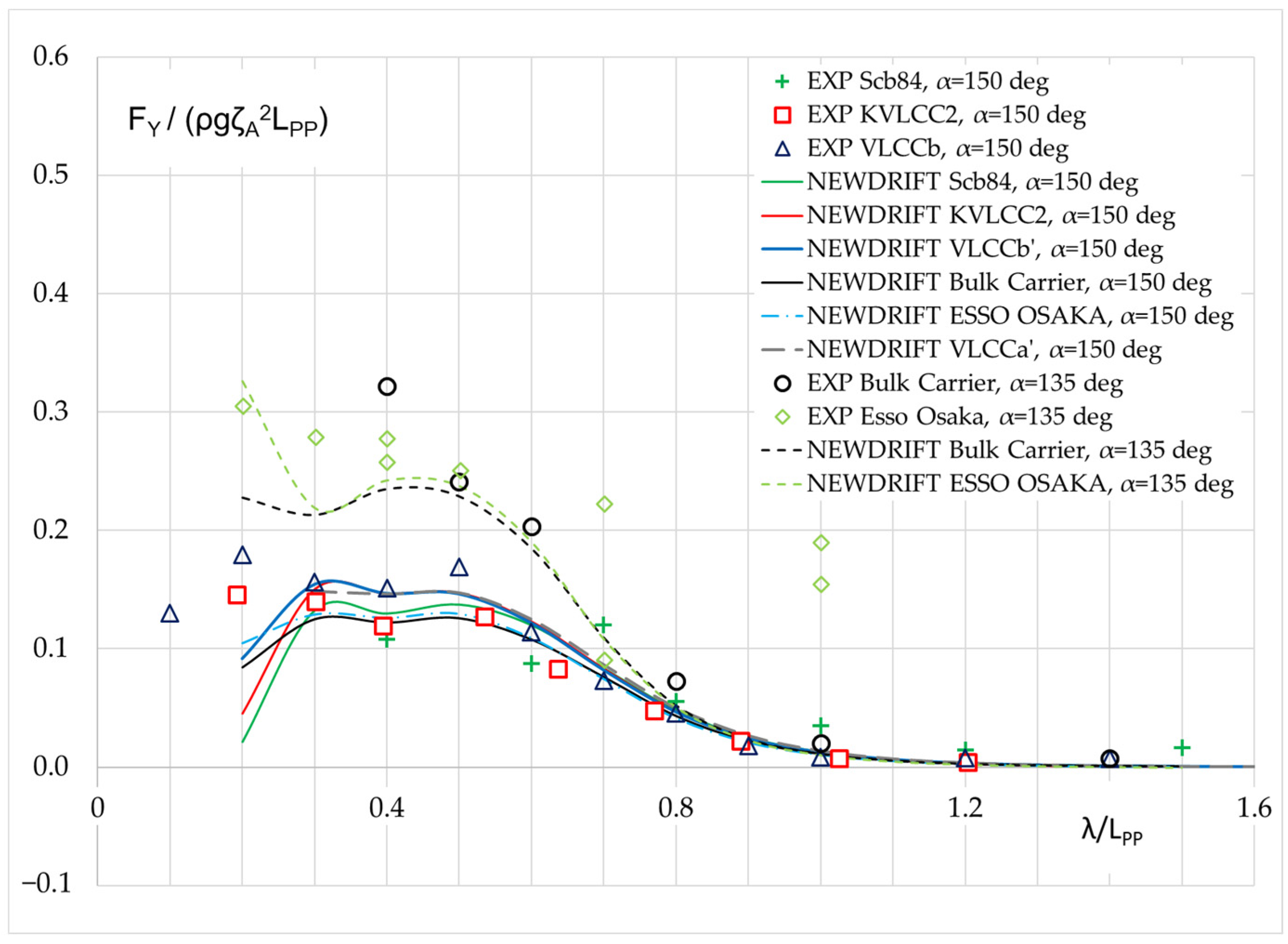
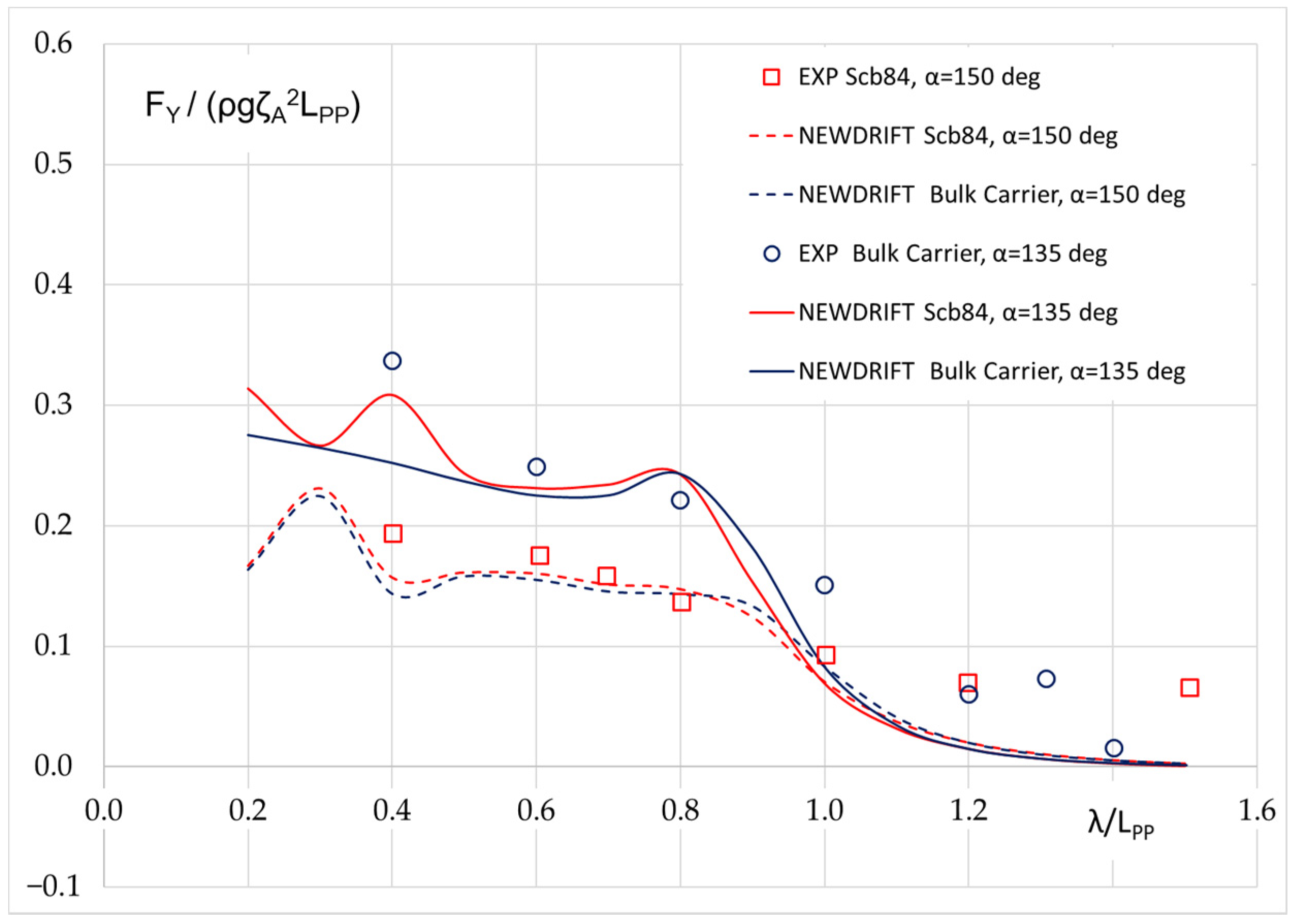
Figure 3 shows the induced mean sway force of five of the test ships in bow waves from two incident directions at zero speed. For α = 135 deg, the experimental data of Esso Osaka and a bulk carrier are available. Reasonable agreement is observed in short waves (λ/LPP = 0.4–0.8). In longer waves, where ship motion plays a role, there are significant deviations as the experiments of Esso Osaka were executed in the motion restrained condition. For α = 150 deg, the experimental data of S-Cb84, KVLCC2 and VLCCb are available. While the measured values are smaller than in the α = 135 deg case, a close agreement is observed among the three sets of data. For both cases, the numerical results for the studied ships show a high degree of similarity except in very short waves, where the local hull form features appear to play an important role.
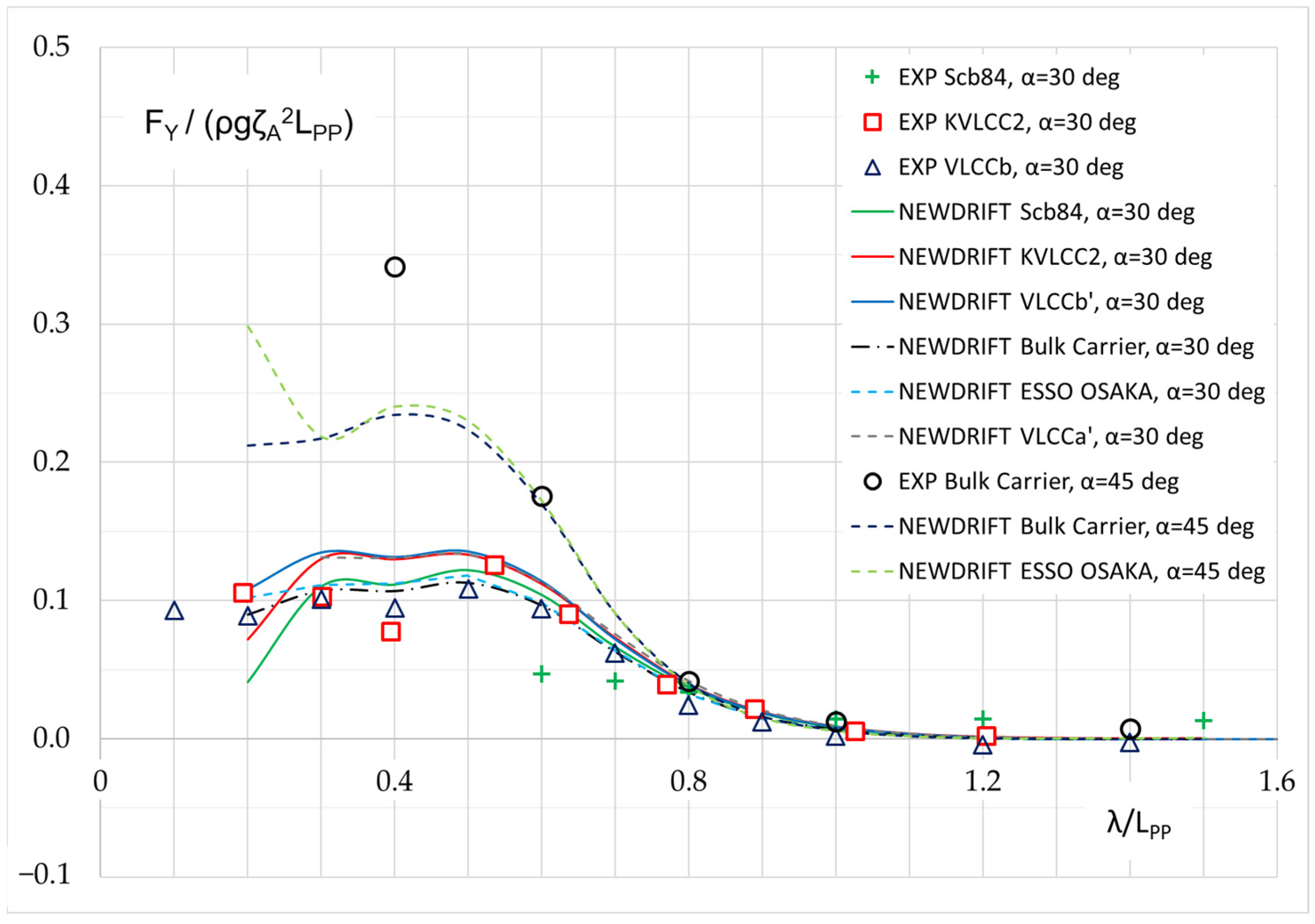
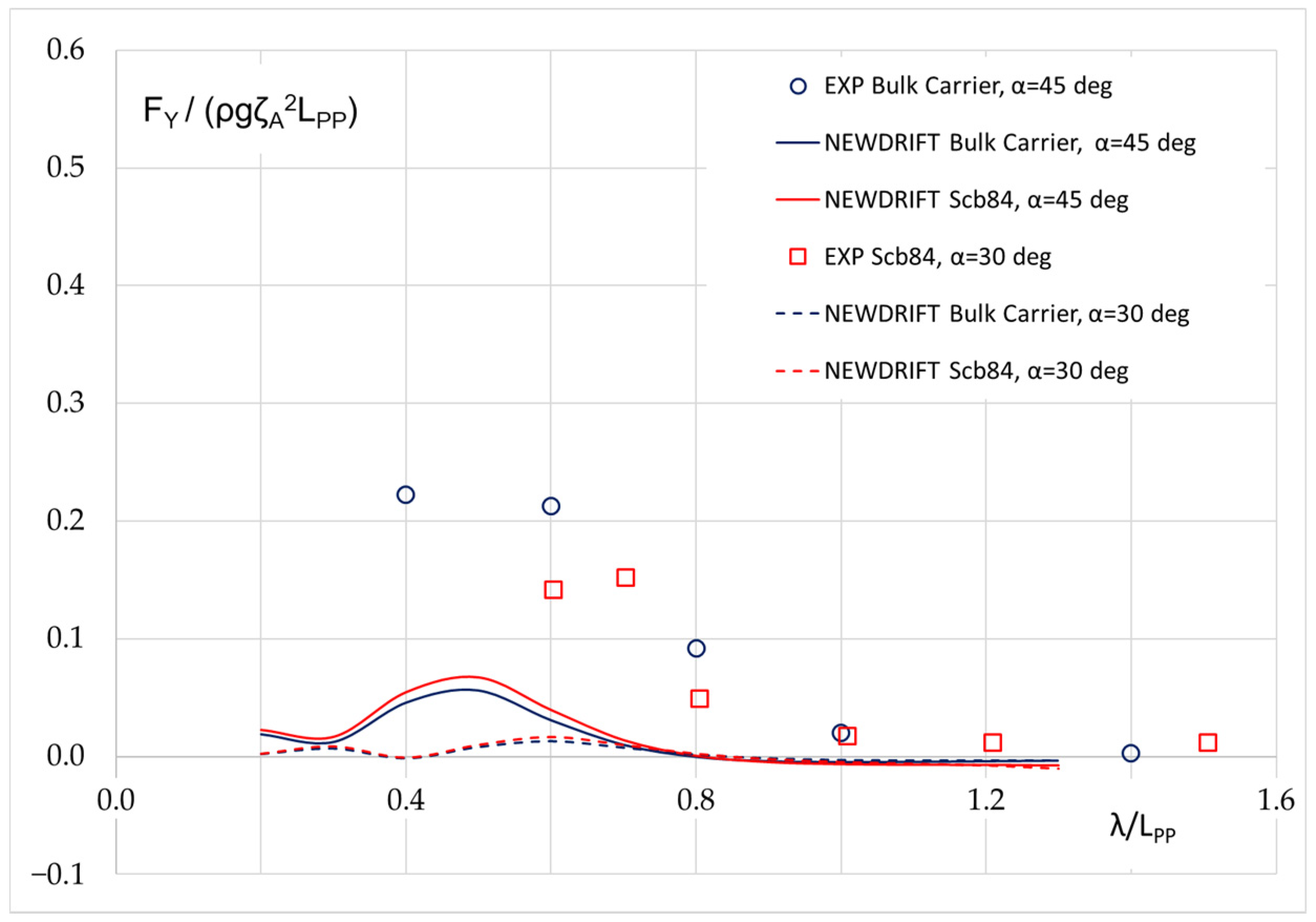
Figure 4 shows the mean sway force of four of the tested ships in stern oblique waves in two incident directions at zero speed. For α = 45 deg, the experimental data of a bulk carrier are available, while for α = 30 deg the experimental data for S-Cb84, KVLCC2 and VLCCb are available. The measured values for α = 30 deg are smaller than in the α = 45 deg case and generally, all three sets of data are close together, despite some scattering that might be due to the different stern forms. In both cases, the numerical results for all studied ships are close, except in very short waves, where deviations are notable. Particularly, the experimental results for the bulk carrier at λ/LPP = 0.4 have a peak and are much larger than the numerically predicted value. This is also observed in the associated work of Kadomatsu et al. [34].
Though the degree of uncertainty of the analyzed set of experimental data is not available to the public, it is useful to briefly comment on the quality of the measurements on the basis of made observations. In this respect, the experimental results depicted in Figure 2, Figure 3 and Figure 4 seem to be in general reliable, except for a few dubious points significantly deviating from trend lines. In terms of the depicted numerical results, it appears that prediction results by NEWDRIFT agree fairly well with experimental results for all wave directions at zero speed.
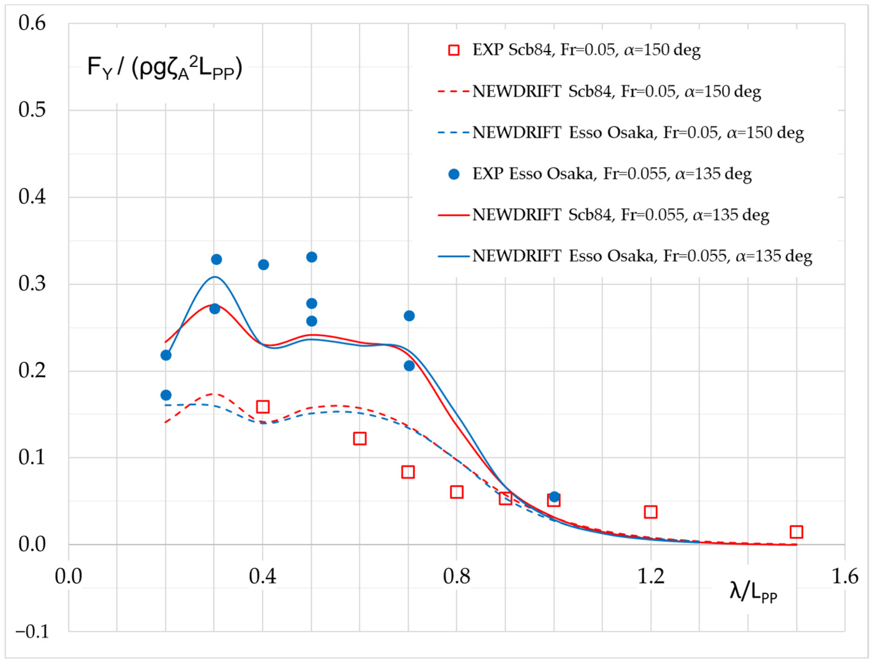
For the cases with forward speed, much less experimental data are available, due to the very limited availability of proper facilities to conduct such tests. Figure 5 shows the experimental results for the Esso Osaka at Fr = 0.055 in waves of α = 135 deg and for Scb-84 at Fr = 0.05 in waves of α = 150 deg; numerical results for both ships in both testing conditions are also added. Good agreement between experimental results and numerical results has been achieved, though it seems that for α = 135 deg, the numerical prediction is slightly lower than the experimental results, while for α = 150 deg, the numerical prediction is slightly higher than the experimental data.
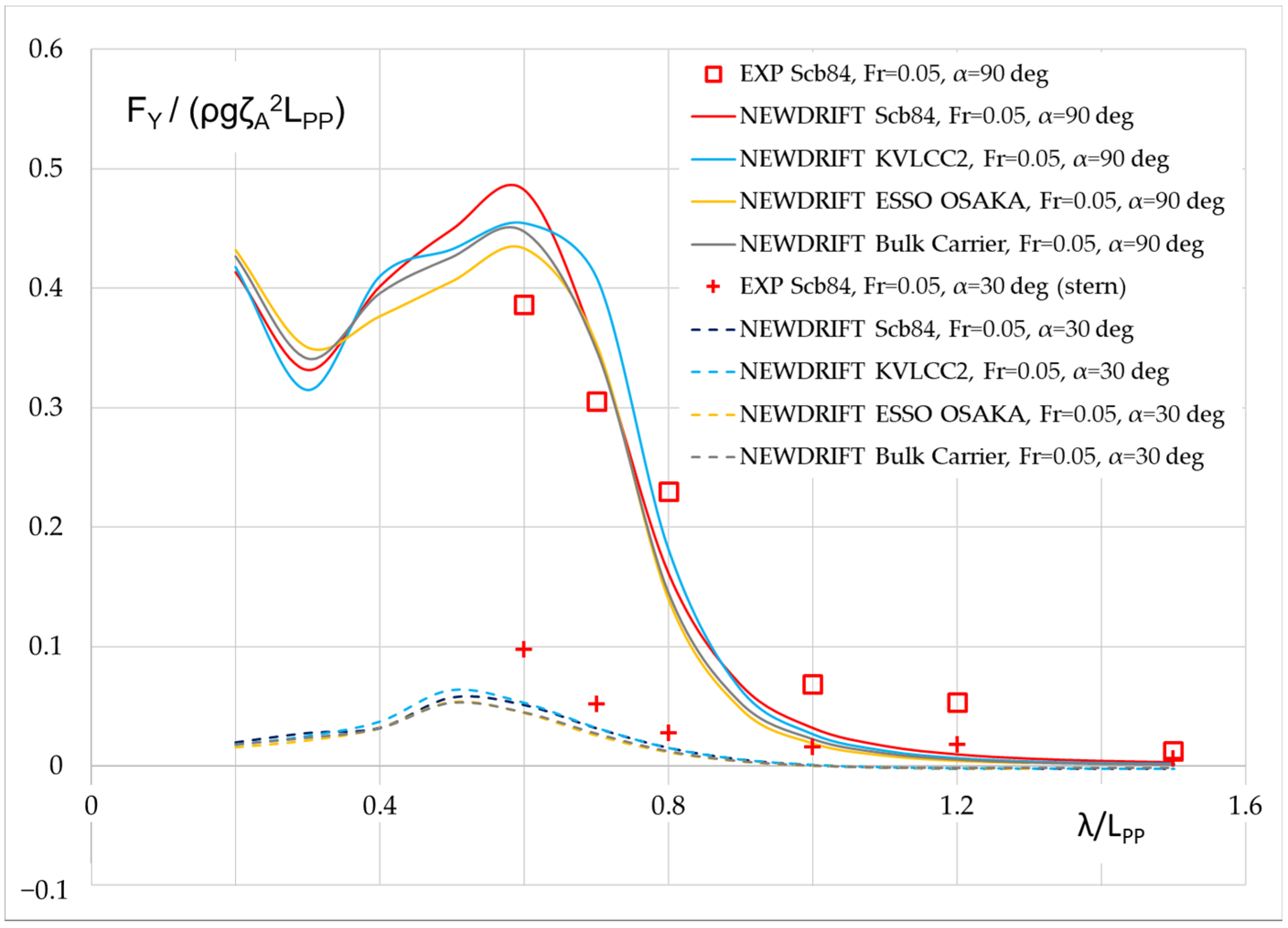
Figure 6 shows the experimental results for S-Cb84 at Fr = 0.05 in beam waves and stern oblique waves, together with the numerical results for the other tested ships for the same testing condition. For α = 90 deg, the numerical prediction is slightly higher than the experimental results. The maximum non-dimensional mean sway force is observed at λ/LPP ≈ 0.6. For α = 30 deg, the numerical prediction is lower than the experimental results, which may be related to insufficiency of the ensuing slender body theory when dealing with a ship sailing in stern oblique waves and at low frequency of encounter.
Figure 7, Figure 8 and Figure 9 present a comparison between the experimental and numerical results for the mean sway force of S-Cb84 and a bulk carrier in beam waves, bow waves and stern oblique waves, at Fr = 0.10. It is observed that in bow and beam waves, the numerical results agree very well with experimental results. However, at this moderate speed, the numerical method significantly underpredicts the mean sway force for both ships in stern quartering waves, which indicates the limitations for the applied method (slender body theory) to account for the forward speed effect at lower frequency of encounter.
5. Development of a Semi-Empirical Formula for the Side Drift Force of Full Type Ships at Low Speeds
Examining both the experimental and numerical results in Figure 2, Figure 3, Figure 4, Figure 5, Figure 6, Figure 7, Figure 8 and Figure 9, we may detect a strong recurring functional pattern for the concerned mean sway force of the tested full ships at low speeds. This encourages us to attempt the development of an empirical formula to approximate the mean sway force in waves, as we did for the mean surge force or added resistance [40,41,42].
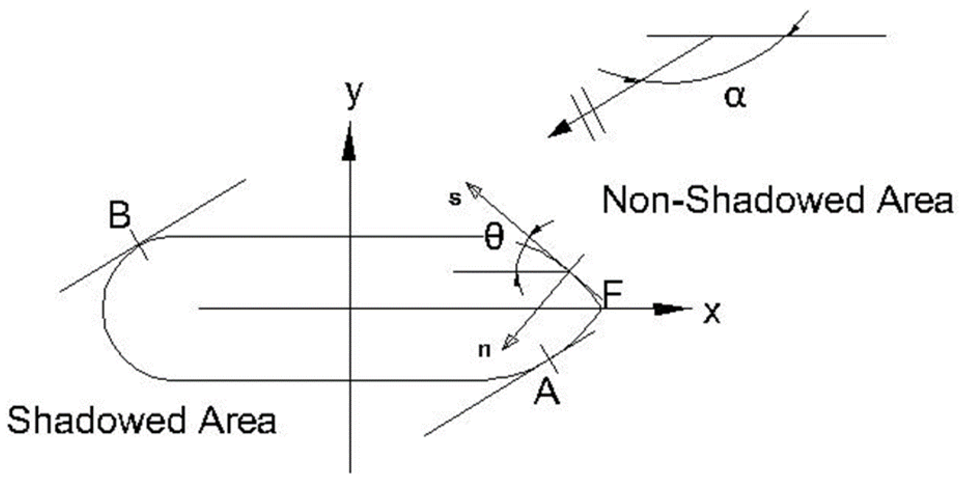
We start from the zero speed case, namely, to consider the mean sway force on the VLCCb’ in beam waves. As shown in Figure 10, the black curve shows the numerical results predicted by NEWDRIFT and it agrees reasonably well with the experimental results. Assuming that the total mean sway force consists of a reflection induced part and a motion induced part, and the diffraction part can be approximated by:
where ρ is density of water, g the gravitational acceleration, ζA the incident wave amplitude, B the beam of a ship, BF(α) is the bluntness coefficient of a ship in oblique waves and it is defined at zero speed as follows:
and R(α) is the generalized reflection coefficient given by Evans and Morris [43]. Liu [44] elaborated Equation (7) in detail.
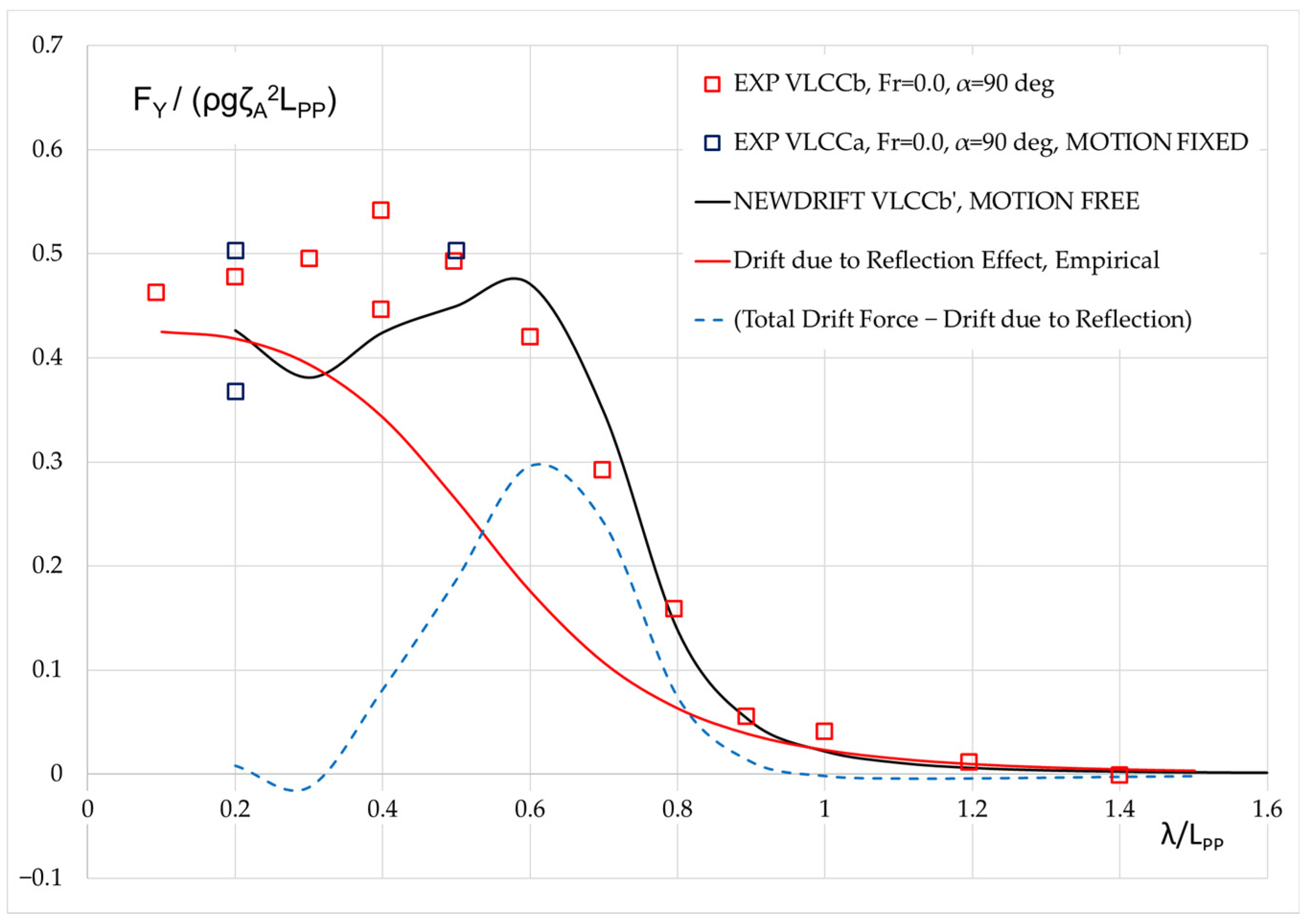
The red curve in Figure 11 shows the mean sway force exerting on the VLCCb’ approximated by Equation (7). Then, the shown dashed blue curve represents the difference between the total mean sway force calculated by NEWDRIFT and the approximate diffraction part of the side drift force, thus, the missing motion induced part. If the dashed blue curve can be properly represented by a formula, then an empirical formula can be formed.
In a previous study [42], it was demonstrated that the component of the mean surge force due to motion effect can be approximated as follows:
At zero speed, the mean surge force and the mean sway force are equivalent physical quantities. Thus, the mean sway force can be approximated similarly, though the various form coefficients will need some tuning. Indeed, the following formula is deduced after some trial-and-error procedures:
with
where λ is the length of the incident wave, the block coefficient of the ship, and the non-dimensional radius of gyration of pitch.
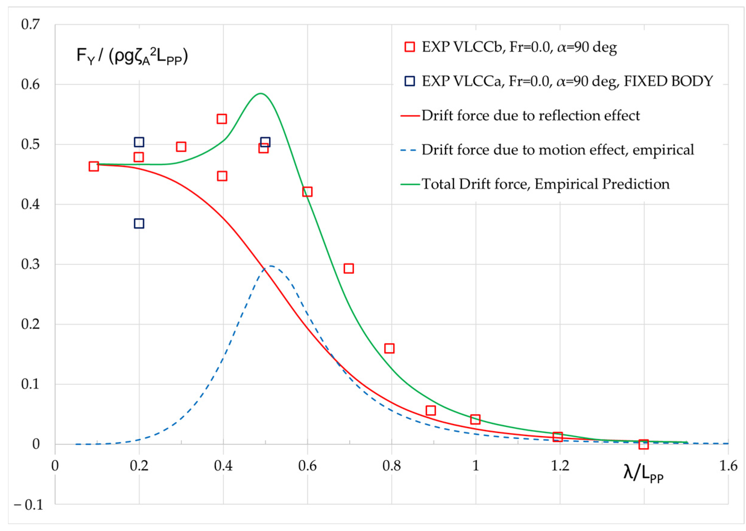
Figure 12 shows the preliminary results of the approximated mean sway force of the VLCCb’ based on Equations (7) and (10) (sum of reflection and motion contributions):
The results based on Equation (11) are herein denoted as “Total drift force, empirical prediction”. Obviously, the obtained results agree very well with the experimental results. It should be noted that the coefficient is presented in a rather simplified form at the moment. It can be further tuned by introducing the effect of the main ship particulars, such as,,,, Fr, etc., so that the formula can be more versatile. This will require, however, more experimental and/or numerical data, as well as details of the test hull forms.
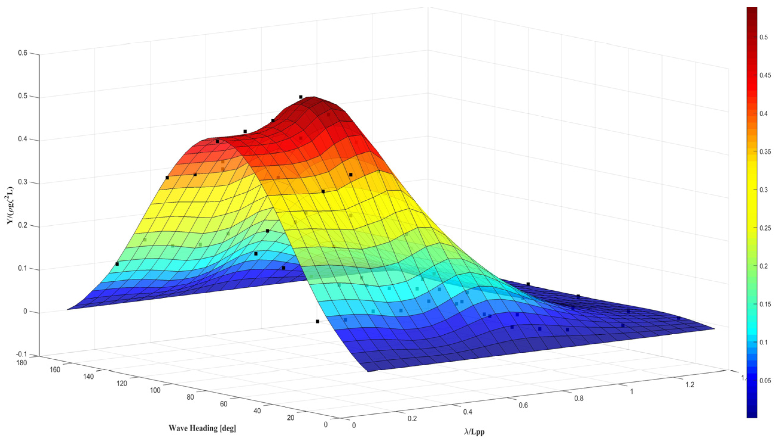
Figure 13 shows the prediction of the mean sway force of the same ship in waves at zero speeds in waves of arbitrary headings by the proposed empirical method in comparison with experimental results.
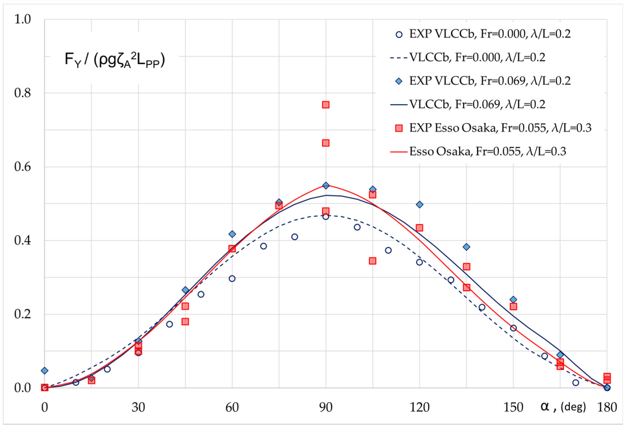
Figure 14 shows the prediction of the mean sway force for two other full ships in waves at low speeds by the proposed empirical method and model experimental values. Examining the results of VLCCb at two speeds, it is noted that the empirical results agree fairly well with the experimental data and that the forward speed effect is also properly predicted. The empirical prediction of the mean sway force for Esso Osaka at Fr = 0.055 in regular waves of λ/LPP = 0.3 also shows an excellent agreement with experimental data.
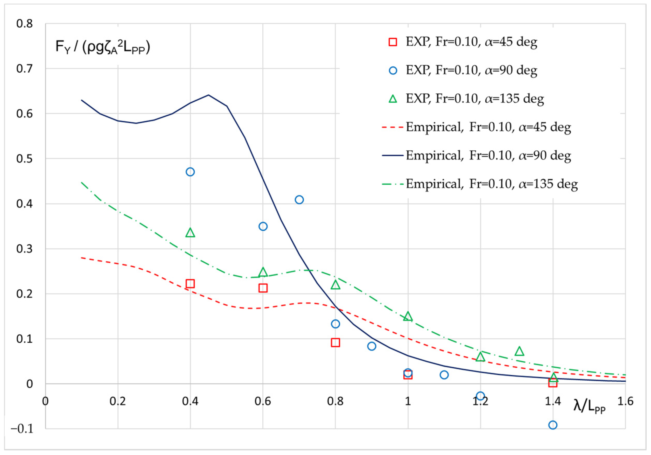
Figure 15 shows the experimental and empirical prediction of the mean sway force of a bulk carrier at a higher speed (Fr = 0.1) in waves of various directions. A reasonable agreement has been observed for all three wave headings. For head waves, the empirical prediction appears to be a bit higher than the experimental results in short waves. As stated, more validation and calibration of the formula can be carried out when more data is available.
6. Summary and Conclusions
In this study, we first analyze a series of published experimental data of the mean sway wave induced forces (side drift) for six full ships at low speeds and various wave headings. A strong recurring pattern was observed in the presented results. In relatively short waves, namely λ/LPP < 0.3, a spreading of the experimental data is observed. This is because the measured values are rather small, while it is also very challenging to generate stable waves of very small lengths. For this reason, in tank tests, the generated waves are rather steep for small wavelengths, which in turn, leads to complicated nonlinear wave–structure interaction phenomena and further exaggerates the scatter. The influence of steepness on the concerned quantity needs further systematic investigation.
In a second step of the presented study, a 3D panel method based on the in-house software NEWDRIFT is further validated by comparing the numerical results for the second order mean sway force in waves at low speeds with the corresponding experimental data for the tested set of six full type ships. It is noted that the mean sway force is most significant in relatively short waves, with the peak being observed at λ/LPP ≈ 0.5–0.6. For λ/LPP > 1.0, the quantities are rather small. This feature is different from that of mean surge force, or the added resistance, which exhibits its non-dimensional maxima, when wavelength is comparable to ship length (close to the heave/pitch motion resonance). Overall, NEWDRIFT delivers satisfactory predictions for the mean sway force, as for the other drift force and moment components.
Finally, we proceed to the development of an empirical formula to approximate the mean sway force using only the main ship particulars and wave parameters, which will enable a wide application in various tasks. Preliminary validation results show that the empirical formula can capture satisfactorily the mean sway force acting on full type ships, at both zero and non-zero, low speeds. In future work, we plan to further develop the proposed empirical formula so that it can deal with various ship types, forward speeds and wave conditions.
Author Contributions
Conceptualization, S.L. and A.P.; methodology, S.L. and A.P.; software, S.L. and A.P.; validation, S.L.; formal analysis, S.L.; investigation, S.L.; data curation, S.L.; writing—original draft preparation, S.L.; writing—review and editing, A.P.; visualization, S.L.; supervision, A.P. All authors have read and agreed to the published version of the manuscript.
Funding
This study was conducted in the framework of the internally funded bilateral research project “Assessment of the Manoeuvering Performance of a Ship in a Seaway” of NTU and NTUA.
Conflicts of Interest
The authors declare no conflict of interest.
References
- Havelock, T.H. The Pressure of Water Waves upon a Fixed Obstacle. Proc. R. Soc. Lond. Ser. A Math. Phys. Sci. 1940, 175, 409–421. [Google Scholar]
- Maruo, H. The drift of a body floating on waves. J. Ship Res. 1960, 4, 1–10. [Google Scholar]
- Newman, J.N. The drift force and moment on ships in waves. J. Ship Res. 1967, 11, 51–60. [Google Scholar]
- Salvesen, N. Second-Order Steady State Forces and Moments on Surface Ships in Oblique Regular Waves. In International Symposium on Dynamics of Marine Vehicles and Structures in Waves; Mechanical Engineering Publications Limited, Univ. College: London, UK, 1974; pp. 212–226. [Google Scholar]
- Gerritsma, J.; Beukelman, W. Analysis of the resistance increase in waves of a fast cargo ship 12. Int. Shipbuild. Prog. 1972, 19, 285–293. [Google Scholar] [CrossRef]
- Salvesen, N.; Tuck, E.O.; Faltinsen, O. Ship motions and sea loads. Trans. Soc. Nav. Archit. Mar. Eng. 1970, 78, 250–287. [Google Scholar]
- Mavrakos, S. The vertical drift force and pitch moment on axisymmetric bodies in regular waves. Appl. Ocean Res. 1988, 10, 207–218. [Google Scholar] [CrossRef]
- Kashiwagi, M. Added Resistance, Wave-Induced Steady Sway Force and Yaw Moment on an Advancing Ship. Ship Technol. Res. (Schiffstech.) 1992, 39, 3–16. [Google Scholar]
- Boese, P. Eine einfache Methode zur Berechnung der Widerstandserhöhung eines Schiffes im Seegang. Ship Technol. Res. 1970, 258, 17. [Google Scholar] [CrossRef]
- Faltinsen, O.M.; Minsaas, K.J.; Liapis, N.; Skjordal, S.O. Prediction of Resistance and Propulsion of a Ship in a Seaway. In Proceedings of the 13th Symposium on Naval Hydrodynamics, Tokyo, Japan, 6–10 October 1980; pp. 505–529. [Google Scholar]
- Papanikolaou, A.; Nowacki, Ζ. Second-Order Theory of Oscillating Cylinders in a Regular Steep Wave. In Proceedings of the l3th ONR Symp., Tokyo, Japan, 6–10 October 1980; pp. 303–333. [Google Scholar]
- Papanikolaou, A.; Zaraphonitis, G. On an Improved Method for the Evaluation of Second-Order Motions and Loads on 3D Floating Bodies in Waves. J. Schiffstech.-Ship Technol. Res. 1987, 34, 170–211. [Google Scholar]
- Pinkster, J. Mean and low frequency wave drifting forces on floating structures. Ocean Eng. 1979, 6, 593–615. [Google Scholar] [CrossRef]
- Zaraphonitis, G.; Papanikolaou, A. Second-order theory and calculations of motions and loads of arbitrarily shaped 3D bodies in waves. Mar. Struct. 1993, 6, 165–185. [Google Scholar] [CrossRef]
- Higo, Y.; Ha, M.K. A Study on Added Resistance of a Restrained Body with Forward Speed in Waves. J. Soc. Nav. Arch. Jpn. 1991, 1991, 75–83. [Google Scholar] [CrossRef] [Green Version]
- Dai, Y.S.; Huang, D.B. The near-field and far-field formulae for the added resistance of ships. J. Harbin Shipbuild. Eng. Inst. 1994, 15, 1–5. [Google Scholar]
- Papanikolaou, A.; Schellin, T.E. A Three Dimensional Panel Method for Motions and Loads of Ships with Forward Speed. Ship Technol. Res. (Schiffstech.) 1992, 39, 147–156. [Google Scholar]
- Joncques, S.A.G. Second Order Forces and Moments Acting on Ships in Waves. Ph.D. Thesis, Technical University of Denmark, Mechanical Engineering, Lyngby, Denmark, 2009. [Google Scholar]
- Chen, X.B. On the Irregular Frequencies Appearing in Wave Diffraction-Radiation Solutions. Int. J. Offshore Polar Eng. 1998, 8, 110–114. [Google Scholar]
- Duan, W.; Li, C. Estimation of added resistance for large blunt ship in waves. J. Mar. Sci. Appl. 2013, 12, 1–12. [Google Scholar] [CrossRef]
- Liu, S.; Papanikolaou, A.; Zaraphonitis, G. Practical Approach to the Added Resistance of a Ship in Short Waves. In Proceedings of the 25th International Offshore and Polar Engineering Conference, Kona, HI, USA, 21–26 June 2015; Volume 3, pp. 11–18. [Google Scholar]
- Ohkusu, M. Added Resistance in Waves of Hull Forms with Blunt Bow. In Proceedings of the 15th Symposium on Naval Hydrodynamics, Hamburg, Germany, 2–7 September 1984; pp. 135–147. [Google Scholar]
- Sakamoto, T.; Baba, E. Minimization of Resistance of Slowing Moving Full Hull Forms in Short Waves. In Proceedings of the 16th Symposium on Naval Hydrodynamics, Berkeley, CA, USA, 13–18 July 1986; pp. 598–612. [Google Scholar]
- Tsujimoto, M.; Kuroda, M.; Shiraishi, K.; Ichinose, Y.; Sogihara, N. Verification on the resistance test in waves using the actual sea model basin. J. Jpn. Soc. Nav. Archit. Ocean Eng. 2012, 16, 33–39. [Google Scholar] [CrossRef] [Green Version]
- Yang, K.K.; Kim, Y.; Jung, Y.W. Enhancement of Asymptotic Formula for Added Resistance of Ships in Short Waves. Ocean Eng. 2018, 148, 211–222. [Google Scholar] [CrossRef]
- Skejic, R.; Faltinsen, O.M. A unified seakeeping and maneuvering analysis of ships in regular waves. J. Mar. Sci. Technol. 2008, 13, 371–394. [Google Scholar] [CrossRef]
- Naito, S.; Mizoguchi, S.; Kagawa, K. Steady forces acting on ships with advance velocity in oblique waves. J. Kansai Soc. Nav. Archit. 1990, 213, 45–50. [Google Scholar]
- Iwashita, H.; Ito, A.; Okada, T.; Ohkusu, M.; Takaki, M.; Mizoguchi, S. Wave Forces Acting on a Blunt Ship with Forward Speed in Oblique Sea. J. Soc. Nav. Arch. Jpn. 1992, 1992, 109–123. [Google Scholar] [CrossRef]
- Ueno, M.; Nimura, T.; Miyazaki, H.; Nonaka, K. Steady Wave Forces and Moment Acting on Ships in Manoeuvring Motion in Short Waves. J. Soc. Nav. Arch. Jpn. 2000, 2000, 163–172. [Google Scholar] [CrossRef] [Green Version]
- Ueno, M.; Nimura, T.; Miyazaki, H.; Nonaka, K.; Haraguchi, T. Model Experiment on Steady Wave Forces and Moment Acting on a Ship a Rest. J. Kansai Soc. Nav. Archit. 2001, 235, 69–77. [Google Scholar]
- SHOPERA Project (2013–2016). Energy Efficient Safe Ship Operation, EU Funded FP7 Project. Grant Agreement Number 605221. Available online: http://www.shopera.org (accessed on 15 March 2020).
- Sprenger, F.; Maron, A.; Delefortrie, G.; Van Zwijnsvoorde, T.; Cura-Hochbaum, A.; Lengwinat, A.; Papanikolaou, A. Experimental Studies on Seakeeping and Manoeuvrability in Adverse Conditions. J. Ship Res. 2017, 61, 131–152. [Google Scholar] [CrossRef] [Green Version]
- Shigunov, V.; El Moctar, O.; Papanikolaou, A.; Potthoff, R.; Liu, S. International benchmark study on numerical simulation methods for prediction of manoeuvrability of ships in waves. Ocean Eng. 2018, 165, 365–385. [Google Scholar] [CrossRef]
- Kadomatsu, K.; Inoue, Y.; Takarada, N. On the Required Minimum Output of Main Propulsion Engine for Large Fat Ship with Considering Manoeuverability in Rough Seas. J. Soc. Nav. Arch. Jpn. 1990, 1990, 171–182. [Google Scholar] [CrossRef] [Green Version]
- Yasukawa, H.; Hirata, N.; Matsumoto, A.; Kuroiwa, R.; Mizokami, S. Evaluations of wave-induced steady forces and turning motion of a full hull ship in waves. J. Mar. Sci. Technol. 2018, 24, 1–15. [Google Scholar] [CrossRef]
- Papanikolaou, A. On integral-equation-methods for the evaluation of motions and loads of arbitrary bodies in waves. Arch. Appl. Mech. 1985, 55, 17–29. [Google Scholar] [CrossRef]
- Liu, S.; Papanikolaou, A.; Zaraphonitis, G. Prediction of added resistance of ships in waves. Ocean Eng. 2011, 38, 641–650. [Google Scholar] [CrossRef]
- Papanikolaou, A. Ship Design-Methodologies of Preliminary Design; Springer: Berlin/Heidelberg, Germany, 2014; p. 628. ISBN1 978-94-017-8751-2. ISBN2 978-94-017-8750-5. [Google Scholar]
- Dafermos, G.K.; Zaraphonitis, G.N.; Papanikolaou, A.D. On an Extended Boundary Method for the Removal of Irregular Frequencies in 3D Pulsating Source Panel Methods. In Proceedings of the 18th International Congress of the Maritime Association of the Mediterranean (IMAM 2019), Varna, Bulgaria, 9–11 September 2019; pp. 53–59. [Google Scholar]
- Liu, S.; Papanikolaou, A. Fast approach to the estimation of the added resistance of ships in head waves. Ocean Eng. 2016, 112, 211–225. [Google Scholar] [CrossRef]
- Liu, S.; Papanikolaou, A. Approximation of the added resistance of ships with small draft or in ballast condition by empirical formula. Proc. Inst. Mech. Eng. Part M J. Eng. Marit. Environ. 2017, 233, 27–40. [Google Scholar] [CrossRef]
- Liu, S.; Papanikolaou, A. Regression analysis of experimental data for added resistance in waves of arbitrary heading and development of a semi-empirical formula. Ocean Eng. 2020, 206, 107357. [Google Scholar] [CrossRef]
- Evans, D.V.; Morris, C.A.N. The Effect of a Fixed Vertical Barrier on Obliquely Incident Surface Waves in Deep Water. IMA J. Appl. Math. 1971, 9, 198–204. [Google Scholar] [CrossRef]
- Liu, S. Revisiting the influence of a ship’s draft on the drift force due to diffraction effect. Ship Technol. Res. (Schiffstech.) 2020. in Press. [Google Scholar]
Figure 1.
Panelization of the underwater hull of S-Cb84 model for 3D panel code NEWDRIFT.

Figure 2.
Mean sway force of six ships in regular beam waves at zero speed.

Figure 3.
Mean sway force of several ships in regular bow waves at zero speed.

Figure 4.
Mean sway force of several ships in regular stern waves at zero speed.

Figure 5.
Mean sway force of two ships in regular bow waves at low speeds.

Figure 6.
Mean sway force of various ships in regular beam and stern oblique waves at low speeds.

Figure 7.
Mean sway force in regular beam waves, Fr = 0.10.

Figure 8.
Mean sway force in regular bow quartering waves, Fr = 0.10.

Figure 9.
Mean sway force in regular stern oblique waves, Fr = 0.10.

Figure 10.
Coordinate system in calculating drift force due to reflection.

Figure 11.
Various components of the mean sway force of a ship in regular beam waves, Fr = 0.0.

Figure 12.
Empirical prediction of the mean sway force of a ship in regular head waves, Fr = 0.0.

Figure 13.
Empirical prediction of the mean sway force of a ship in waves, Fr = 0.0.

Figure 14.
Prediction of the mean sway force by proposed empirical formula for two full type ships in regular waves at low speeds.
Figure 14.
Prediction of the mean sway force by proposed empirical formula for two full type ships in regular waves at low speeds.

Figure 15.
Empirical prediction of the mean sway force of a bulk carrier in waves, Fr = 0.10.


Table 1.
Main particulars, associated coefficients and ratios, and testing conditions of several full ships.
Table 1.
Main particulars, associated coefficients and ratios, and testing conditions of several full ships.
| Item | Unit | VLCCa | VLCCb | KVLCC2 | S-Cb84 | Bulk Carrier | Esso Osaka |
|---|---|---|---|---|---|---|---|
| Model Length | m | 3.14 | 2.97 | 4.00 | 3.10 | 2.91 | 4.00 |
| L/B | - | 5.08 | 5.52 | 5.52 | 5.52 | 5.70 | 6.13 |
| B/T | - | 3.05 | 3.01 | 2.79 | 2.79 | 2.70 | 2.44 |
| L/T | - | 15.49 | 16.62 | 15.40 | 15.40 | 15.39 | 14.96 |
| CB | - | 0.81 | 0.81 | 0.81 | 0.84 | 0.83 | 0.83 |
| Speed, Fr | - | 0.0–0.2 | 0–0.069 | 0.0 | 0.0–0.05–0.10 | 0.0–0.10 | 0.0–0.055 |
| Motion | - | restrained | free | free | free | free | restrained |
| Reference | - | [28] | [29,30] | [32,33] | [35] | [34] | [27] |
© 2020 by the authors. Licensee MDPI, Basel, Switzerland. This article is an open access article distributed under the terms and conditions of the Creative Commons Attribution (CC BY) license (http://creativecommons.org/licenses/by/4.0/).
Share and Cite
MDPI and ACS Style
Liu, S.; Papanikolaou, A. Prediction of the Side Drift Force of Full Ships Advancing in Waves at Low Speeds. J. Mar. Sci. Eng. 2020, 8, 377. https://doi.org/10.3390/jmse8050377
AMA Style
Liu S, Papanikolaou A. Prediction of the Side Drift Force of Full Ships Advancing in Waves at Low Speeds. Journal of Marine Science and Engineering. 2020; 8(5):377. https://doi.org/10.3390/jmse8050377
Chicago/Turabian StyleLiu, Shukui, and Apostolos Papanikolaou. 2020. "Prediction of the Side Drift Force of Full Ships Advancing in Waves at Low Speeds" Journal of Marine Science and Engineering 8, no. 5: 377. https://doi.org/10.3390/jmse8050377
Note that from the first issue of 2016, this journal uses article numbers instead of page numbers. See further details here.