Wear Resistance of High C High Si Steel with Low Retained Austenite Content and Kinetically Activated Bainite

1
Materials testing department, Institute of Metals and Technology (IMT), Lepi pot 11, SI-1000 Ljubljana, Slovenia
2
Faculty of Mechanical Engineering, University of Maribor, Smetanova 17, SI-2000 Maribor, Slovenia
3
SIJ Metal Ravne d.o.o., Koroška cesta 14, SI-2390 Ravne na Koroškem, Slovenia
*
Authors to whom correspondence should be addressed.
Metals 2020, 10(5), 672; https://doi.org/10.3390/met10050672
Submission received: 14 April 2020
/
Revised: 18 May 2020
/
Accepted: 19 May 2020
/
Published: 21 May 2020
(This article belongs to the Special Issue Friction and Wear of Metals)
Abstract
:A novel high C high Si carbide free bainitic steel was developed for the production of cold work tools, knives, and rolls, requiring high hardness, toughness, as well as abrasive/adhesive wear resistance and resistance to galling at low costs. The steel was tribologically tested in dry sliding conditions under abrasive and adhesive wear mode, facilitated by using alumina and bearing steel ball as a counter-material, respectively. It was determined that carbide dissolution occurs under high contact pressures, thereby enriching the surrounding matrix with carbon and locally increasing the retained austenite content. The high retained austenite at the sliding interface increases the steels work hardening capacity and promotes superior wear resistance when compared to much more alloyed cold work tool steel, such as AISI D2. The steel has a high resistance to galling as determined by sliding against a soft steel bar due to its chemical composition.
1. Introduction
The wear resistance of tool steels depends upon the microstructure, including the spacing, size, and type of hard particles, as well as the ability of the matrix to absorb energy, all defining steel hardness and toughness [1].
Carbide-free bainitic microstructures are known to exhibit superior combination of mechanical and wear resistant properties. This is provided by the very fine scale of bainitic ferrite plates that are embedded within a matrix of retained austenite and a stress/strain induced transformation of the retained austenite phase into very hard untempered martensite. Phase transformation gives rise to work hardening, which is known as the transformation-induced plasticity effect [2]. However, low transformation temperatures between 200 and 300 °C are required in order to obtain fine bainitic ferrite subunits [3]. These steels contain high concentrations of carbon (close to 0.8%) and silicon (~1.5%) to ensure low transformation temperatures and a carbide-free bainitic microstructure [4]. Rapid bainite transformation kinetics at temperatures, even below 200 °C, can be achieved by the introduction of nano-scale precipitates, which deplete the adjacent matrix of carbon and lead to the bainitic ferrite subunits nucleation [3].
The increase in surface hardness due to stress/strain induced transformation under conditions of dry rolling and sliding in extremely fine pearlite steel, has been evaluated while using nano-indentation and can reach values of up to 750 HV [5]. This also led to improved wear resistance, which was enhanced by reducing the distance between ferrite and cementite lamellas. Refined pearlite has a greater flow stress and work hardening rate, while finer cementite is able to accommodate more deformation prior to fracture [6]. In this sense it is not important how the retained austenite was stabilized, due to the effect of Si or Al [7], thermally [8] or mechanically, provided the resulting toughness is sufficient to prevent the initiation and propagation of cracks from the surface. This was well illustrated in a study where the wear resistance of carbide free lower bainite, martensite, and pearlite in the same super bainite steel was practically the same [9]. During abrasive wear, the retained austenite content of the austempered steel was reduced from an initial 44% to a final value of 12%, which is even lower than present after conventional quenching to martensite. On this example it was shown that a hard but brittle microstructure does not perform much better under abrasive conditions than a softer, but more ductile, one. Of course, depending on the hardness the wear mechanism will change accordingly. Therefore, it is important that the toughness of the material is sufficient for arresting crack propagation from the contact surface toward the bulk of the tool.
At the same hardness, the wear resistance of medium carbon steels has been reported to be up to 25% higher when treated into a carbide free bainitic microstructure as opposed to quenching and tempering into martensite. Furthermore, for carbide free bainitic medium carbon steels the surface hardness increased much more due to their higher work hardening capacity [10]. In some cases, very high abrasive wear resistance is reported for low temperature carbide free bainitic steels, with their wear rate being as low as 1% of that exhibit by 100Cr6 steel, when heat treated to a needle-like lower bainite with hardness of about 60 HRC and the strength level of 2.3 GPa [11]. This high abrasive wear resistance is largely attributed to the retained austenite content. However, while the retained austenite contributes to the steel wear resistance, its effect on toughness has been shown to be strongly deteriorating, when present in amounts that are close to or above 10% [12]. Therefore, theoretically, it would be advantageous to locally introduce the retained austenite into the surface layer, while not compromising the toughness of the bulk material.
A method by which this could be accomplished is by the well-known phenomena of carbide dissolution under pressure. This effect has been documented in the field of bearing steels [13]. During operation under heavy loads, the bearing steels undergo several microstructural changes, one of which is dislocation accumulation, particularly in heavily deformed regions. The accumulated dislocations shear carbide particles, which size is then reduced via dissolution, controlled by the migration of carbon from cementite towards dislocations. This requires a constant supply of carbon-unsaturated dislocations in the neighborhood of dissolving carbide particles. The dissolution tendency and rate are proportional to alloying elements content and dislocations density. Furthermore, smaller particles tend to dissolve much faster when compared to coarser ones, which can be intuitively explained in terms of a higher surface energy. However, there is also a threshold driving force value (12–15 kJ/mol), below which precipitates coarsening will occur rather than the dissolution [13].
The aim of this research work was to investigate whether the effect of carbides dissolution under high pressure can be exploited under severe wear conditions, with the retained austenite only being generated in the vicinity of the hard abrading particles, such as oxide scale and hard wear particles, or more generally within regions of high contact pressure. Thus, increasing the wear resistance at the interface without compromising the toughness of the bulk material. Within a novel group of steel alloys termed kinetically activated bainite (KAB) steels, which have been introduced previously [14], this concept enables the obtainment of very fine bainitic microstructures with a low retained austenite content. A KAB steel, which fulfils the above description, has been developed and its resistance to abrasive and adhesive wear evaluated and compared to conventional D2-type tool steel in the current work.
2. Materials and Methods
The material used in this work is new custom made high Si carbide-free bainitic cold work tool steel with the nominal chemical composition that is given in Table 1. As a reference, commercial AISI D2 cold work tool steel has been used.
SIHARD S250 was cast in the form of 1 ton ingots, diffusion annealed at 1220 °C for 24 h, followed by hot rolling to the final shape of 62 mm × 32 mm flat profiles. Additionally, AISI D2 tool steel was cast in 1 ton ingot and then rolled to the same final dimension of 62 mm × 32 mm. Both of the steels were then soft annealed and test specimens machined from each steel.
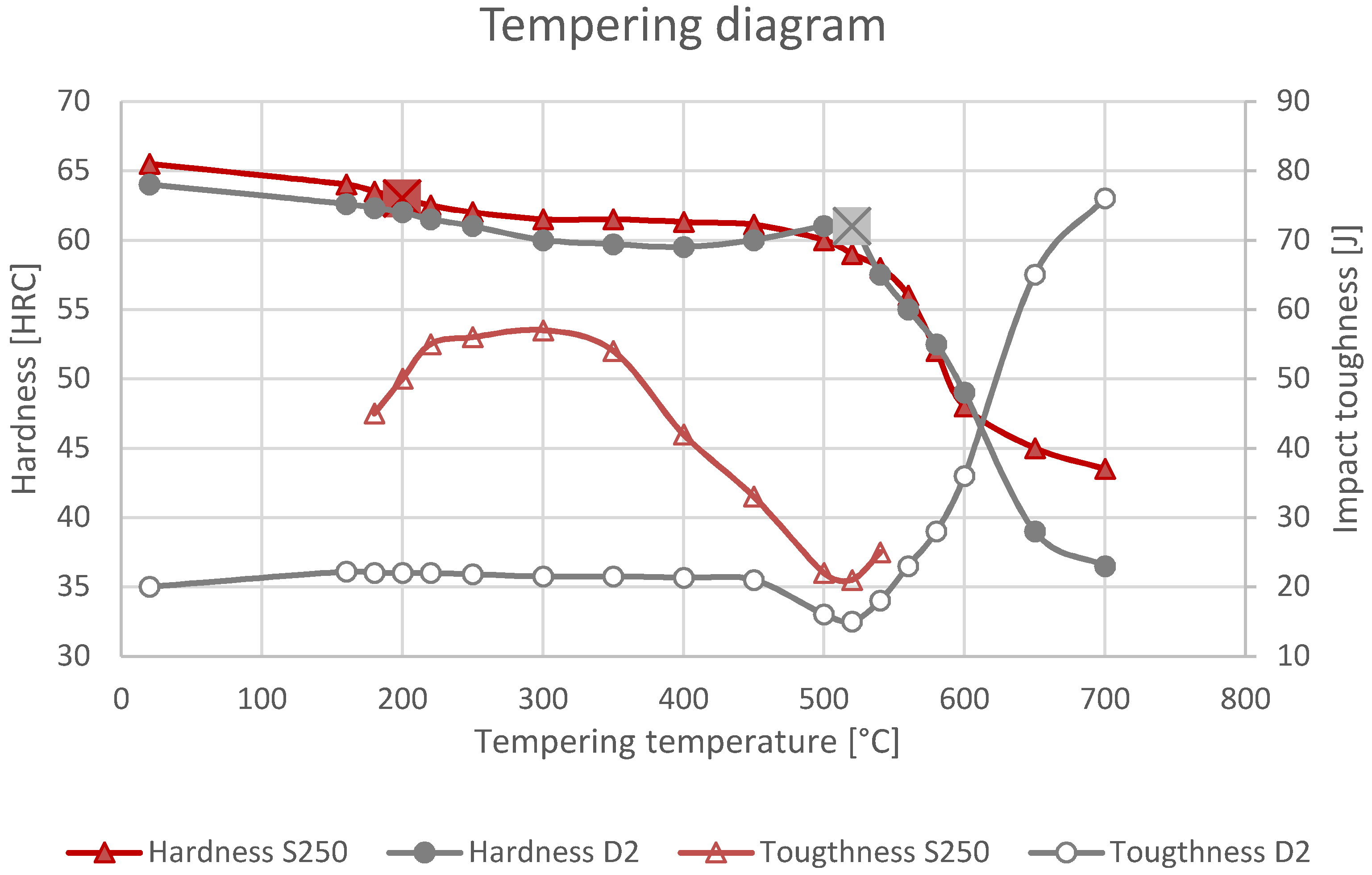
As can be seen from the tempering diagram that is shown in Figure 1, the hardness of SIHARD S250 steel (measured with Instron B2000 machine (Instron, Norwood, MA, USA), using Rockwell C method according to ASTM E18 standard [15]) is continuously decreasing with increased tempering temperature, while a relatively high impact toughness (un-notched impact specimens; 7 mm × 10 mm × 55 mm) is obtainable within the desired working hardness range of 61–64 HRC, reached at low tempering temperatures. Furthermore, the tempering stability of SIHARD S250 is higher than for commercial AISI D2 steel, which can be explained by its high Si content.
The heat treatment conditions of the two investigated steels applied prior to testing are indicated with boxed X. The SIHARD S250 tool steel was quenched from 980 °C in oil and tempered once at 200 °C for 2 h to a hardness of 63 HRC and impact toughness of 50 J. On the other hand, AISI D2 was tempered twice at 520 °C, resulting in a similar hardness of about 62 HRC, but much lower toughness of only 15 J.
Compression tests were performed on standard short cylindrical test samples with a diameter of Φ13 mm and a length of 25 mm, according to the ASTM E9 standard [16]. Testing was done with a force of 320 kN corresponding to a compressive stress of 2.4 GPa, which did not exceed the elastic limit of the steel.
The wear testing of the investigated tool steels in the final heat treated condition was performed under reciprocating dry sliding conditions at room temperature while using the ball-on-disc contact configuration. The abrasive wear mode was simulated by performing tests with Al2O3 ball (20 mm) sliding against polished tool steel disc (Ra = 0.10 µm) at a nominal contact pressure of 1.5 GPa (FN = 102 N) and an average sliding speeds of 0.01 (f = 1 Hz, stoke of 4 mm) and 0.12 m/s (f = 15 Hz, stroke of 4 mm), respectively. The wear volume of the removed tool steel material has been determined by three-dimensional (3D) profilometric analysis. On the other hand, adhesive wear determined as the volume of the counter-ball material adhered to the contact surface of the tool steel disc was simulated by performing sliding tests with a hardened 100Cr6 steel ball (20 mm, 58 HRC). In this case, tests were performed at a nominal contact pressure of 1 GPa (FN = 40 N) and sliding speed of 0.12 m/s. For all wear tests (abrasive and adhesive), the total sliding distance was 100 m.
The resulting abrasive wear volume and wear rate calculated as wear volume divided by normal load and sliding distance are the average of 10 sliding tests performed at two different sliding speeds and the adhesive wear rate the average of five sliding tests performed at single sliding speed of 0.12 m/s.
The galling resistance was examined by a load-scanning test [17], where investigated tool steels were sliding against soft annealed S235J2 low carbon steel at a gradually increasing load. The tests were performed under dry sliding conditions and room temperature, sliding speed of 0.1 m/s, and load range of 100–1000 N. After the test critical loads for the beginning of low carbon steel transfer to the tool steel surface (LC1) and transfer layer build-up (LC2) were determined by microscopic analysis of the wear track.
3. Results and Discussion
3.1. Microstructure
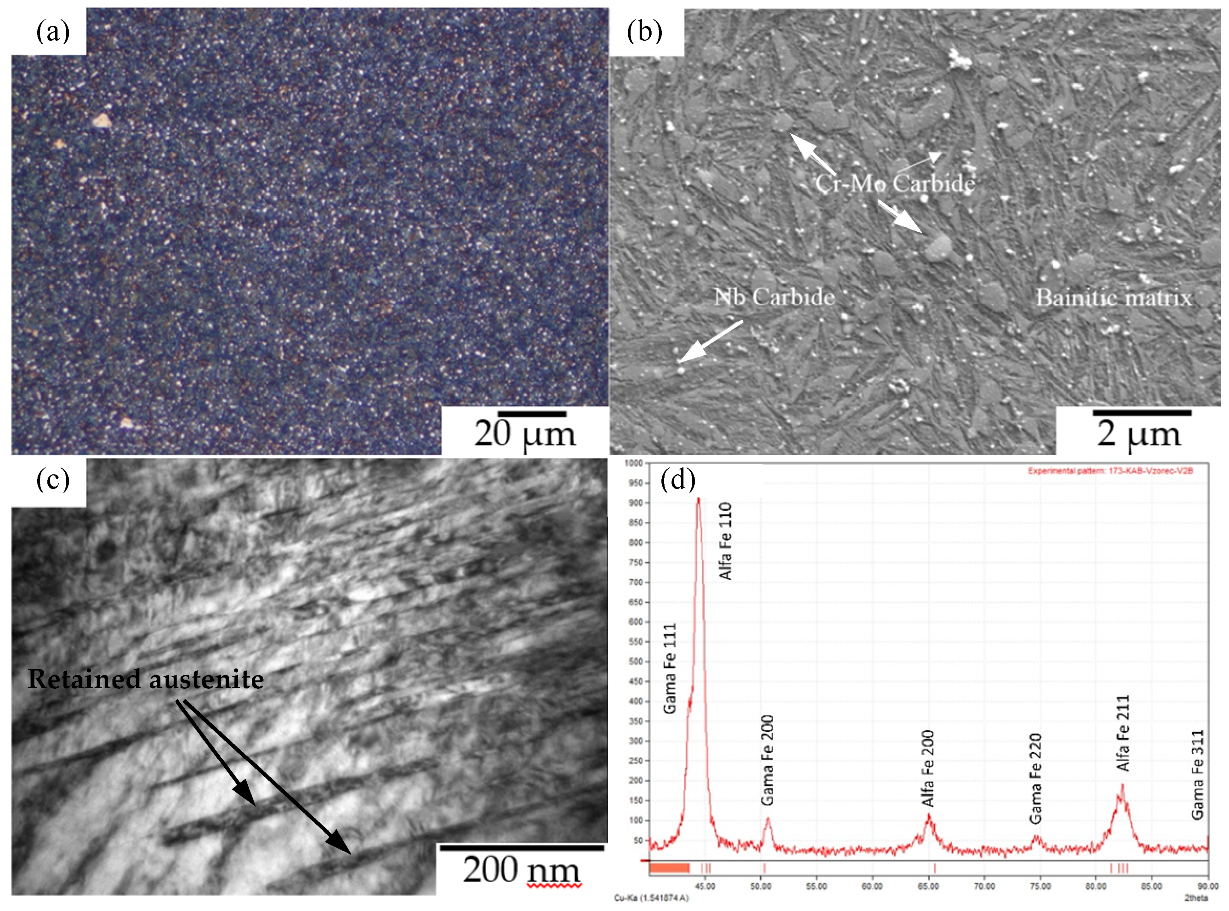
The microstructure of SIHARD S250 steel after heat treatment (Figure 2) has been revealed by preparing metallographic samples and etching with Vilella and 7% aqueous Na2S2O5 for light and FESEM microscopy, respectively. It was determined to be predominantly lower bainite with numerous carbides, some martensite, and a small amount of retained austenite (Figure 2a,b). FESEM/EDS observation of the microstructure shows the fine bainitic matrix and numerous fine carbides that are based on Cr-Mo-Fe and NbTiC, as also confirmed by XRD analysis (Figure 2d). The very fine bainitic ferrite structure can be seen in the HRTEM micrograph in Figure 2c. The individual bainitic ferrite plates are very thin and locally separated by films of retained austenite (dark phase). A low retained austenite content is also determine using X-ray diffraction, whereby the corresponding graph and Rietveld analysis can be seen in Figure 2d.
The phase fractions of ferrite and retained austenite were determined using X-ray diffraction (Figure 2d) and the Rietveld Refinement method. X-ray diffraction spectrums were obtained on a Bruker D8 Advance (Bruker, Billerica, MA, USA), operating using an Cu anode at 40 kV/40 mA and a secondary graphite monochromator within a 2theta range between 40° and 90° for a total measuring time of 3 h. Prior to measurements, the samples were deep-etched in order to remove any deformed surface layer. Prior deformation microstructure of SIHARD S250 tool steel contains about 4.4% Cr-Mo rich M23C6-type carbides and about 3.5% of retained austenite, as shown in Table 2. On the other hand, AISI D2 has much higher fraction of carbides, of about 18.5%, predominantly of the M7C3 type [18].
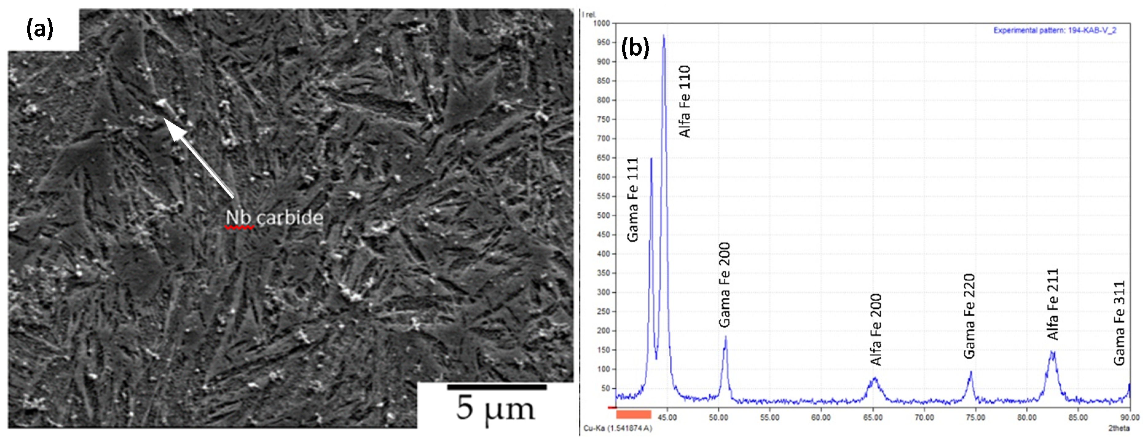
Standard compression samples were subjected to a stress level of 2.4 GPa and then the microstructure and phase fractions were analysed by preparing metallographic specimens and X-ray diffraction analysis in order to assess the influence of compressive stress on the carbide fraction. Table 3 and Figure 3 present the results.
The coarser Cr-Mo rich carbides (M23C6) are no longer present in the microstructure, and we observe an additional peak in the X-ray diffraction spectrum (Figure 3b) corresponding to austenite (γ111 at 43°), with its content being increased to about 36% (Table 3), as can be seen form Figure 3a. Increased austenite content is further indicated by the increased intensity of γ peaks, as shown in Figure 3b. Therefore, the microstructural observations of the specimens exposed to compression test suggest that the Cr-Mo rich carbides essentially dissoluted, whereas the smaller and also more stable Nb-Ti rich carbides remained unaffected by the compressive stress (Figure 3).
3.2. Wear Resistance
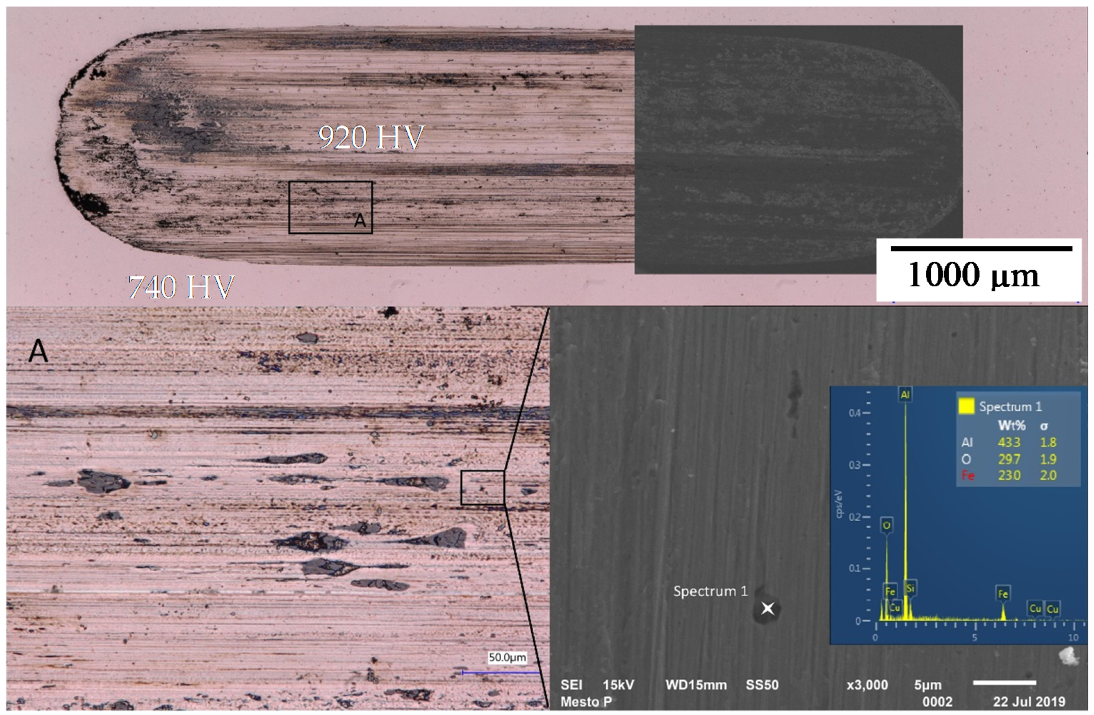
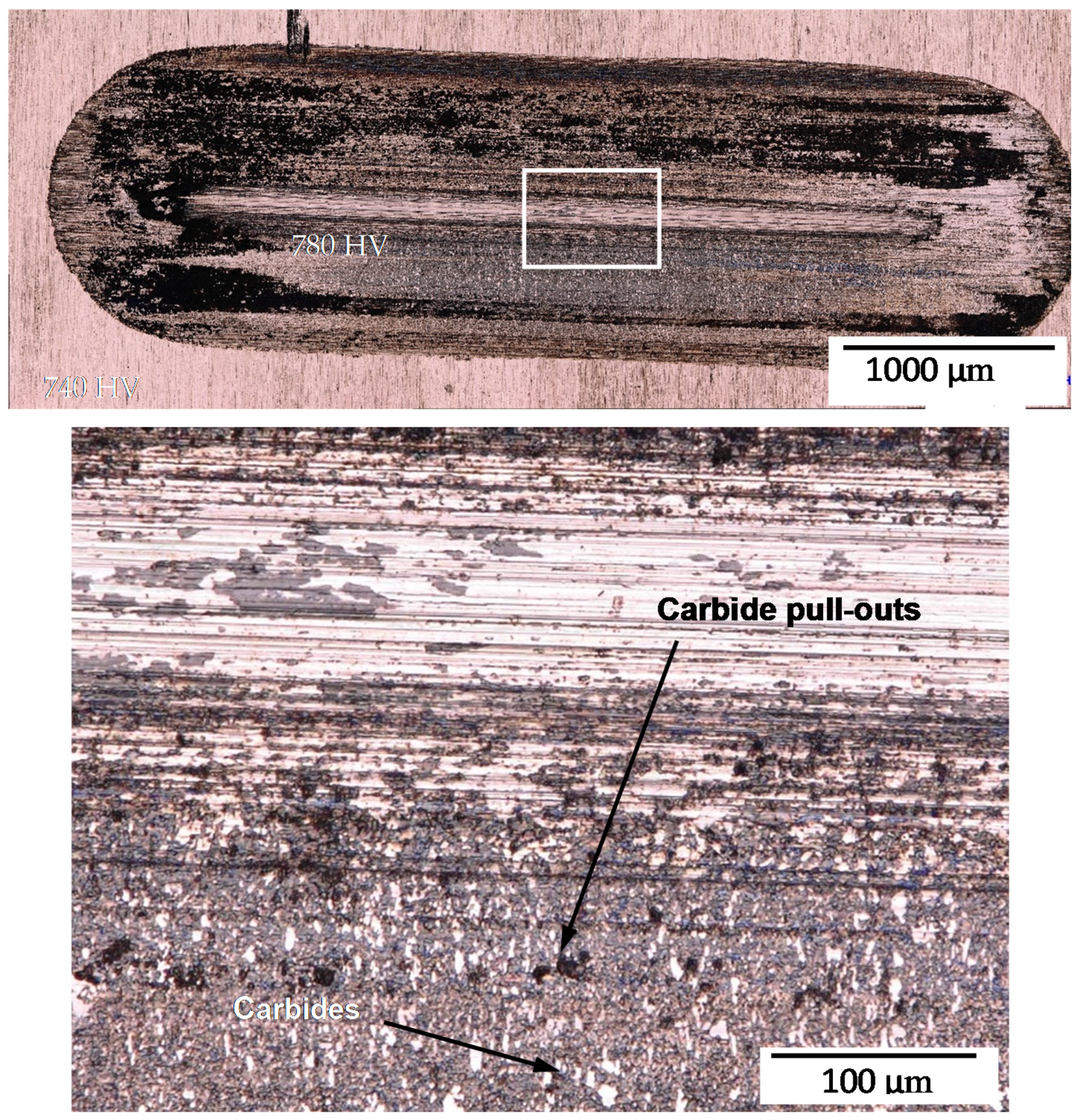
Although the hardness of both steels is comparable the wear failure mode is different since SIHARD S250 does not contain any coarse carbides that contribute to its wear resistance. This steel resists the penetration of abrading hard particles by work hardening as well as the dissipation of energy via phase transformation and due to its higher toughness. It was observed that, in the case of abrasive wear tests the surface hardness, as measured with Instron Tukon 2100B microhardness tester (Instron, Norwood, MA, USA) according to ASTM E384 standard [19], increased from an initial 740 HV0.01 to about 920 HV0.01 within the wear scar, which is shown in Figure 4. This is close to the measured hardness of martensite in 1% C steels [20]. When considering that retained austenite comprised only about 35% of the microstructure the actual hardness of the stress/strain induced martensite can be expected to be substantially higher, but would require higher resolution measurements (i.e., nano-indentation) to be confirmed. The grey particles were characterized by microchemical (EDS) analysis and have shown to be wear debris from the alumina ball (Al2O3). In contrast, the surface hardness on the sample of AISI D2 tool steel only increased marginally from 740 HV0.01 to 780 HV0.01. The wear is accompanied by breaking and falling out of carbides, as indicated in Figure 5.
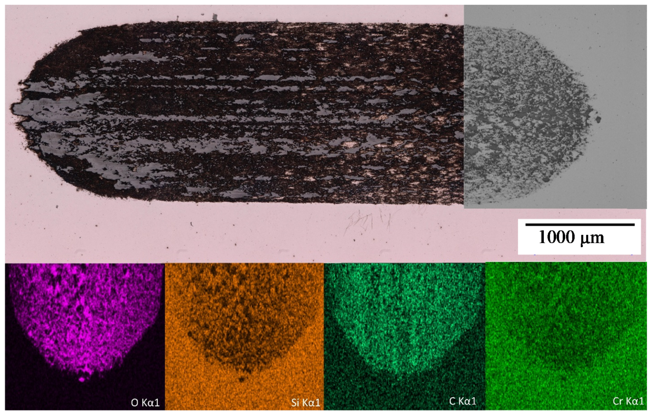
Adhesive wear causes a redistribution of elements present in the base material towards the sliding interface (Figure 6), unlike abrasive wear with typical scratches and grooves being present within the wear scar (Figure 4). In this manner, a Si rich surface layer is formed on the contact surface, seen as a dark grey area in Figure 6. In addition to Si, the surface is also enriched in O and C, whereby concentrations of other alloying elements changed negligibly. The Si rich regions correspond to areas with low oxygen content, whereas C is redistributed without a discernible pattern. The enrichment of carbon can be explained by process of carbide dissolution under pressure discussed earlier, whereby the carbon from the dissolved carbides was pushed further into the steel, thus enriching the surface layer. A possible explanation is the difference in dislocation density between the bearing steel ball made from 100Cr6 and the investigated steel. Carbon could be trapped at this defects and pushed inward during the wear test. The exact depth of C-rich layer was not measured, but, based on Vickers microhardness measurements and EDS depth analysis, we can estimate that the C-rich layer thickness is at least 10 µm. The current steel has a comparable carbon content to the 100 Cr6 bearing ball, so that the measurement error due to local adhesion of the bearing ball to the surface can be considered to be negligible.
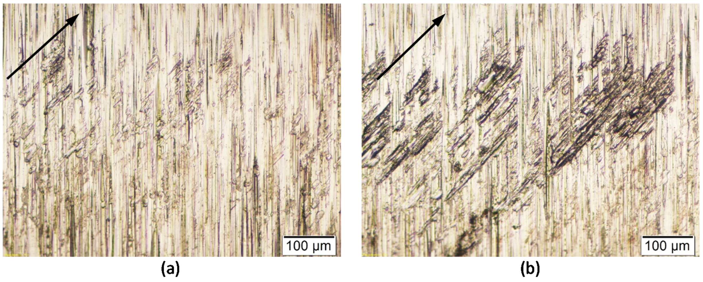
Galling is a form of wear that is highly dependent on the chemical compatibility of the materials in contact. Alloying elements addition to tool steels can reduce strength of the chemical bonds with the softer work material and, therefore, improve the tools resistance to galling wear mode, as has been shown for a Cu alloyed cold work tool steel [21]. This effect is confirmed in the current study, where the high C high Si grade tool steel performed especially well when in sliding contact with soft low-C steel. The critical loads for the onset of galling as well as transfer layer build-up (Figure 7) is more than twice as high as compared to commercial AISI D2 tool steel (Table 4). Increased galling resistance of tool steels is also promoted by high matrix hardness [22], which is very prominent in the current alloy where secondary carbides are no longer present at the wear surface.
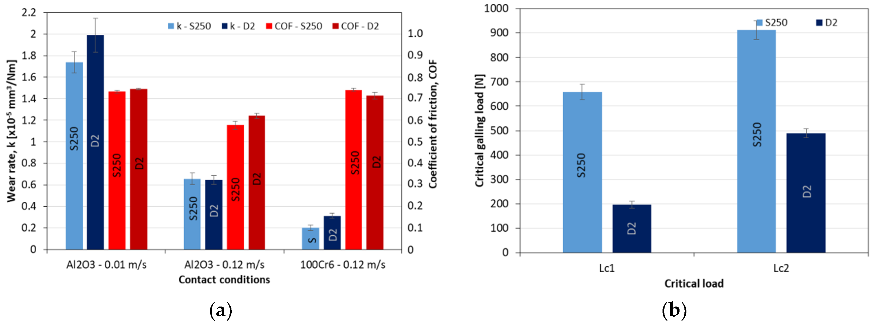
The results of wear and galling tests are summarized in Table 4 and graphically presented in Figure 8, where they are compared to the commonly used cold work toll steel AISI D2 as a reference. Under dry reciprocating sliding abrasive wear against Al2O3 ball AISI D2 tool steel shows an average wear rate of 1.094 × 10⁻⁵ mm3/Nm, with about three times larger wear rate (~2.00 × 10⁻⁵ mm3/Nm) being observed under low sliding speed conditions than for high sliding speed conditions (~0.6 × 10⁻⁵ mm3/Nm). Additionally, the average coefficient of friction follows the same trend, being 0.74 and 0.62, respectively. In the case of high C high Si S250 tool steel, the average abrasive wear rate has decreased for 7.5%, down to 1.017 × 10⁻⁵ mm3/Nm. However, the main improvement has been observed for low sliding speed conditions, as shown in Figure 8a. Additionally, in the case of S250 steel wear rate and average coefficient of friction under low sliding speed conditions are lower (k = 1.74 × 10⁻⁵ mm3/Nm, µ = 0.73) than for high sliding speed conditions (k = 0.65 × 10⁻⁵ mm3/Nm, µ = 58). For adhesive wear against 100Cr6 ball high C high Si S250 tool steel gives even higher improvement of 55%, although showing slightly higher friction (0.71 vs. 0.74). The much better adhesive wear resistance of S250 tool steel is also confirmed by the galling test results and higher critical loads for galling initiation (LC1) and transfer laxer build-up (LC2), Figure 8b.
4. Conclusions
Superior wear resistance properties were obtained in the current high C high Si bainitic steel. The current steel combines good impact properties due to its low retained austenite content, the latter, however, increases remarkably as the secondary Cr-rich carbides dissolve under pressure, which is indicated during the adhesive wear resistance test by sliding against a hardened bearing steel ball, as the surface of the wear track was substantially enriched with C.
A similar effect can be accounted for the high abrasive wear resistance, which exceeds even that of highly alloyed cold work tool steel AISI D2, as well. However, during abrasive wear test carbon enrichment was not observed, which is likely due to the more intense surface scratching and C-rich layer removal in the form of wear debris by the alumina ball during sliding.
SIHARD S250 carbide free bainitic steel also shows greatly improved galling resistance. Carbides are commonly found as the galling initiation spots and by their elimination and dissolution combined with increased surface hardness galling resistance can be substantially improved.
This steel is deemed particularly suitable for cold forming of all kinds of sheet steels, including high strength and stainless grades, due to the good combination of mechanical and anti-wear properties.
5. Patents
Part of the work reported herein has been filed for a patent at the Slovenian patent office under nr. P-201900181.
Author Contributions
This article was conceptualized by B.P. and P.K., B.P. conducted the main investigation and wear resistance testing, B.P. and P.K. curated the data and prepared the original draft; Review and editing was conducted by B.P. and M.B. The work was completed under supervision of B.P., who also administrated the project and provided necessary resources. Authors contributed to the microstructural characterization in the following way: P.K. color metallography and stereo microscopy, M.B. FESEM Characterization. All authors have read and agreed to the published version of the manuscript.
Funding
The authors acknowledge the financial support from the Slovenian Research Agency (research core funding No. P2-0050).
Acknowledgments
The authors would like to express their sincere gratitude to Henrik Kaker for helpful discussions, help with SEM characterizations and XRD measurements. The authors also extend a special thanks to Darja Feispour, for her help with HRTEM characterization.
Conflicts of Interest
The authors declare no conflict of interest.
References
- Bhattacharyya, D.; Hajra, A.; Basu, A.; Jana, S. The effect of grain size on the wear characteristics of high speed steel tools. Wear 1977, 42, 63–69. [Google Scholar] [CrossRef]
- De Cooman, B. Structure–properties relationship in TRIP steels containing carbide-free bainite. Curr. Opin. Solid State Mater. Sci. 2004, 8, 285–303. [Google Scholar] [CrossRef]
- Kirbiš, P.; Vuherer, T.; Irgolic, T.; Anzel, I. Metallographic Analysis of Kinetically Activated Bainite (KAB) Welds. Met. Microstruct. Anal. 2015, 4, 570–578. [Google Scholar] [CrossRef]
- Bhadeshia, H.K.D.H. Nanostructured bainite. Proc. R. Soc. Math. Phys. Eng. Sci. 2010, 466, 3–18. [Google Scholar] [CrossRef] [Green Version]
- Das Bakshi, S.; Leiro, A.; Prakash, B.; Bhadeshia, H.K.D.H. Dry rolling/sliding wear of nanostructured pearlite. Mater. Sci. Technol. 2015, 31, 1735–1744. [Google Scholar] [CrossRef]
- Rigney, D.A. Viewpoint set on materials aspects of wear-introdection. Scr. Mater. 1990, 24, 799–803. [Google Scholar] [CrossRef]
- Wang, M.M.; Lv, B.; Yang, Z.N.; Zhang, F.C. Wear resistance of bainite steels that contain aluminium. Mater. Sci. Technol. 2016, 32, 1–9. [Google Scholar] [CrossRef]
- Mohanty, O. On the stabilization of retained austenite: Mechanism and kinetics. Mater. Sci. Eng. B 1995, 32, 267–278. [Google Scholar] [CrossRef]
- Das Bakshi, S. Wear of Fine Pearlite, Nanostructured Bainite and Martensite. Ph.D. Thesis, University of Cambridge, Cambridge, UK, 2017. [Google Scholar]
- Gola, A.M.; Ghadamgahi, M.; Ooi, S.W. Microstructure evolution of carbide-free bainitic steels under abrasive wear conditions. Wear 2017, 376, 975–982. [Google Scholar] [CrossRef]
- Sourmail, T.; Caballero, F.G.; Garcia-Mateo, C.; Smanio, V.; Ziegler, C.; Kuntz, M.; Elvira, R.; Leiro, A.; Vuorinen, E.; Teeri, T. Evaluation of potential of high Si high C steel nanostructured bainite for wear and fatigue applications. Mater. Sci. Technol. 2013, 29, 1166–1173. [Google Scholar] [CrossRef]
- Kirbiš, P.; Pirtovšek, T.; Anžel, I.; Bruncko, M. Designing Tough Nanostructured Bainite. In Proceedings of the Contributed Papers from Materials Science and Technology 2017, Pittsburgh, PA, USA, 8 October 2018; pp. 466–473. [Google Scholar]
- Kang, J.H.; Rivera-Díaz-Del-Castillo, P.E.G. Carbide dissolution in bearing steels. Comput. Mater. Sci. 2013, 67, 364–372. [Google Scholar] [CrossRef]
- Kirbiš, P.; Pirtovšek, T.V.; Anžel, I.; Brunčko, M. Metallographic Analysis of Kinetically Activated Bainite (KAB) Steels. Met. Microstruct. Anal. 2018, 7, 643–649. [Google Scholar] [CrossRef]
- ASTM E18-18, Standard Test Methods for Rockwell Hardness of Metallic Materials, 2020; ASTM International: West Conshohocken, PA, USA, 2018.
- ASTM E9-19, Standard Test Methods of Compression Testing of Metallic Materials at Room Temperature; ASTM International: West Conshohocken, PA, USA, 2019.
- Podgornik, B.; Hogmark, S.; Pezdirnik, J. Comparison between different test methods for evaluation of galling properties of surface engineered tool surfaces. Wear 2004, 257, 843–851. [Google Scholar] [CrossRef]
- Pirtovšek, T.V.; Kugler, G.; Terčelj, M. The behaviour of the carbides of ledeburitic AISI D2 tool steel during multiple hot deformation cycles. Mater. Charact. 2013, 83, 97–108. [Google Scholar] [CrossRef]
- ASTM E384-17, Standard Test Method for Microindentation Hardness of Materials, 2017; ASTM International: West Conshohocken, PA, USA, 2017.
- Mola, J.; Ren, M. On the hardness of high carbon ferrous martensite. IOP Conf. Series Mater. Sci. Eng. 2018, 373, 012004. [Google Scholar] [CrossRef]
- Ko, D.C.; Kim, S.G.; Kim, B.M. Influence of microstructure on galling resistance of cold-work tool steels with different chemical compositions when sliding against ultra-high-strength steel sheets under dry condition. Wear 2015, 338–339, 362–371. [Google Scholar] [CrossRef]
- Gåård, A. Influence of tool microstructure on galling resistance. Tribol. Int. 2013, 57, 251–256. [Google Scholar] [CrossRef]
Figure 1.
Tempering diagram of SIHARD S250 and commercial AISI D2 tool steels; Heat treatment conditions applied prior to testing are indicated with boxed X.
Figure 1.
Tempering diagram of SIHARD S250 and commercial AISI D2 tool steels; Heat treatment conditions applied prior to testing are indicated with boxed X.

Figure 2.
Initial microstructure and corresponding rentnogram of heat treated SIHARD S250 STEEL; (a) OM micrograph, (b) FESEM micrograph, (c) HRTEM micrograph, and (d) X-ray diffraction spectrum.
Figure 2.
Initial microstructure and corresponding rentnogram of heat treated SIHARD S250 STEEL; (a) OM micrograph, (b) FESEM micrograph, (c) HRTEM micrograph, and (d) X-ray diffraction spectrum.

Figure 3.
(a) Microstructure of steel after compression test, and (b) corresponding X-ray diffraction spectrum.
Figure 3.
(a) Microstructure of steel after compression test, and (b) corresponding X-ray diffraction spectrum.

Figure 4.
Abrasive wear test scar of SIHARD S250 steel with the corresponding SEM images and EDS spectra.
Figure 4.
Abrasive wear test scar of SIHARD S250 steel with the corresponding SEM images and EDS spectra.

Figure 5.
Abrasive wear test scar of AISI D2 tool steel.

Figure 6.
Adhesive wear test scar of SIHARD S250 steel when sliding against a hardened 100Cr6 bearing steel ball, with corresponding EDS mapping.
Figure 6.
Adhesive wear test scar of SIHARD S250 steel when sliding against a hardened 100Cr6 bearing steel ball, with corresponding EDS mapping.

Figure 7.
Galling test results for SIHARD S250 steel sliding against soft annealed low-C steel: (a) galling initiation and (b) transfer layer build-up (arrows indicate sliding direction).
Figure 7.
Galling test results for SIHARD S250 steel sliding against soft annealed low-C steel: (a) galling initiation and (b) transfer layer build-up (arrows indicate sliding direction).

Figure 8.
Tribological test results: (a) wear rate and average coefficient of friction for abrasive and adhesive wear testing, (b) critical loads in galling test.
Figure 8.
Tribological test results: (a) wear rate and average coefficient of friction for abrasive and adhesive wear testing, (b) critical loads in galling test.


Table 1.
Nominal compositions of characterized steels (in wt.%).
| Steel/Composition | C | Si | Mn | Mo | Cr | V | Ti | Nb | B |
|---|---|---|---|---|---|---|---|---|---|
| High C-Si/SIHARD S250 | 1 | 2.8 | 0.5 | 0.6 | 2 | 0.2 | 0.04 | 0.04 | 0.005 |
| D2/Wr. Nr: 1.2379 | 1.49 | 0.26 | 0.23 | 0.75 | 11.9 | 1.05 | 0.005 | / | / |
Table 2.
Phase fractions of SIHARD S250 and AISI D2 steel in the hardened condition.
| Steel/Phase | α | γ | Carbides |
|---|---|---|---|
| SIHARD S250 | 92. | 3.5 | 4.4 (M23C6) |
| D2/Wr. Nr: 1.2379 | 81.5 | 0 | 18.5 (M7C3) |
Table 3.
Phase fractions in SIHARD S250 steel after applied compression load.
| Steel/Phase | α | γ | M23C6 |
|---|---|---|---|
| SIHARD S250 | 61.1 | 35.9 | / |
Table 4.
Wear resistance of SIHARD S250 in comparison to AISI D2 tool steel at a hardness level of ~62 HRC.
Table 4.
Wear resistance of SIHARD S250 in comparison to AISI D2 tool steel at a hardness level of ~62 HRC.
| Steel | Average Abrasive Wear Rate | Average Adhesive Wear Rate | Galling Resistance | |
|---|---|---|---|---|
| LC1 | LC2 | |||
| AISI D2/W.Nr. 1.2379 | 1.094 × 10⁻⁵ mm3/Nm | 3.140 × 10⁻⁶ mm3/Nm | 200 N | 490 N |
| High C-Si/SIHARD S250 | 1.017 × 10⁻⁵ mm3/Nm | 2.020 × 10⁻⁶ mm3/Nm | 660 N | 910 N |
| Improvement | 7.5% | 55.5% | 330% | 85.7% |
© 2020 by the authors. Licensee MDPI, Basel, Switzerland. This article is an open access article distributed under the terms and conditions of the Creative Commons Attribution (CC BY) license (http://creativecommons.org/licenses/by/4.0/).
Share and Cite
MDPI and ACS Style
Podgornik, B.; Brunčko, M.; Kirbiš, P. Wear Resistance of High C High Si Steel with Low Retained Austenite Content and Kinetically Activated Bainite. Metals 2020, 10, 672. https://doi.org/10.3390/met10050672
AMA Style
Podgornik B, Brunčko M, Kirbiš P. Wear Resistance of High C High Si Steel with Low Retained Austenite Content and Kinetically Activated Bainite. Metals. 2020; 10(5):672. https://doi.org/10.3390/met10050672
Chicago/Turabian StylePodgornik, Bojan, Mihael Brunčko, and Peter Kirbiš. 2020. "Wear Resistance of High C High Si Steel with Low Retained Austenite Content and Kinetically Activated Bainite" Metals 10, no. 5: 672. https://doi.org/10.3390/met10050672
Note that from the first issue of 2016, this journal uses article numbers instead of page numbers. See further details here.