A Novel Microwave and Induction Heating Applicator for Metal Making: Design and Testing


1
Department of Engineering “Enzo Ferrari,” University of Modena and Reggio Emilia, via Vivarelli 10/1, 41121 Modena, Italy
2
Paul Wurth Italia SpA, Via Balleydier 7, 16149 Genova, Italy
3
Studio Perugi, 16038 Genova, Italy
*
Author to whom correspondence should be addressed.
Metals 2020, 10(5), 676; https://doi.org/10.3390/met10050676
Submission received: 29 April 2020
/
Revised: 15 May 2020
/
Accepted: 19 May 2020
/
Published: 21 May 2020
(This article belongs to the Special Issue Electromagnetic Processing of Metals)
Abstract
:The use of microwave heating in primary metallurgy is gaining an increasing interest due to the possibility to selectively process ores and to volumetrically heat large amounts of low-thermal conductivity minerals. In this paper the study, development and testing of a new applicator combining the use of microwave and induction heating for rapid reduction of metal containing oxides is described. Numerical simulation was used in order to achieve the proper control over heat generation, considering the use of microwave solid state generators. A prototype, with a capacity up to 5 liters of standard input feed but with the predisposition for continuous processing has been designed, built and tested on reference loads like iron oxide powders and pellets. Results on the microwave heating part of the applicator indicate that it allows to efficiently and rapidly process these kinds of loads, which change from dielectric to conductors as reduction proceeds. The use of variable frequency solid state microwave generators allows to maximize energy efficiency and to controllably change the heating pattern inside the load.
1. Introduction
Current processes for the extraction of metals from their respective ores are characterized by high energy consumption and the release of environmentally undesirable by-products, including large quantities of fine particulate, SO2, COx and NOx [1]. In particular, ore reduction processes are based on the use of fossil fuels, with consequent high CO2 emissions, which make primary metallurgy critical with reference to the international effort in CO2 reduction plans. Moreover, normally these technologies require a complex raw material preparation, to fulfill process requirements, including additional plant units, with their relevant consumptions, emissions and investments.
To overcome these limits, the use of microwave energy in materials processing has been studied for nearly sixty years [2,3,4], addressing the possible selective, rapid and volumetric heating offered by this technique. Researchers in the last few decades started suggesting microwave heating as an alternative way for rapid and uniform heating of pellets [5]. Its implementation, both coupled with conventional heating techniques or as pure microwave heating, is expected to lead to further advantages in terms of faster throughput [6]. For these reasons, microwave heating has been extensively explored in various fields of materials processing [7], for both chemical and metallurgical industries [2,3,5] but also in energy and the environmental field [8].
Microwave heating is an energy transfer to electrically nonconductive materials, converting such energy into heat dependently on their electric, dielectric and magnetic properties [9,10]. It thus provides an alternative to the burning of fossil fuels and can be proficiently used to perform the initial heating which is functional to other electro-heat techniques, like induction heating or electric arc heating [1]
In contrast to all other commonly used methods [2], microwaves exhibits unique characteristics such as volumetric and selective heating [7]. The main benefits of exploiting microwave energy in thermally activated processes stem from the specificity of microwave energy absorption, which can be used also against unfavorable temperature gradients [3]. When applied to low thermal conductivity loads or relatively large solid loads, microwave heating can lead to many exceptional advantages over conventional processing methods, including generation of peculiar temperature profiles, reduction in process time [3], saving of pre-treatment units with faster processing and both energy and cost savings and greater sustainability (CO2 emission reduction). As a matter of fact, the heat generation inside the load eliminates the need for consuming energy on heating the walls of the furnace or reactor, its massive components and heat carriers. As a result, the use of microwave heating is expected to allow to significantly lower energy consumption, especially in high-temperature processes, since heat losses grow dramatically with an increase in the process temperature. Moreover, it was reported in literature the possible existence of the so-called ”non-thermal effect,” though its nature is still debated [8], which becomes relevant when solid state diffusion is involved, like during sintering. In many cases microwave processing is capable of improving the product quality or it leads to results that cannot be achieved conventionally [2]. An idea of the energy saving potential of microwave processing can be inferred from the results of a number of comparative studies regarding sintering or synthesis of specific alloys [2]. For instance, the reactive sintering of high entropy alloys by microwave synthetic route, starting from metallic powders, allows the formation of a minimal fraction of liquid phase, leading to the possibility of achieving microwave assisted near-net shape processing [11]. By this way the limits of current melting technologies (defects formation) or conventional solid state ones (time demanding) was overcome but with the drawback of some residual porosity ascribable to the pressure-less conditions used [12,13]. Comparison to other thermal (heating in furnace) and not thermal techniques (mechanical alloying) and to literature results (arc melting) allowed to evaluate the specific energy consumption of the different synthetic route. Microwave heating resulted the less energy intensive one, in the experimental conditions investigated. The small dimensions of the microwave applicator used and the short synthesis time makes this synthetic route interesting from a process intensification point of view and the benefits become particularly relevant in case of manufacturing of near net shape parts is required [14].
The application of microwave heating to the metallurgical field, where large quantities of low thermal conductivity oxides or sulphides are used, is the natural consequence of this kind of heat generation process, but, as explained later, with some possible issues regarding the processing of loads which undergo phase transformations. Concerning conductive loads, generally, it is known that a bulk metal reflects microwaves; however, metal particles can be heated [15] and in case of ferromagnetic powders, the surface heating rate achievable can result even higher, indicating that magnetism is related to the heating mechanism. However, many processes of the primary metallurgy start from non-conductive loads but can end with conductive ones, possibly even in the molten state.
The earliest application of microwave energy to metallurgy can be traced back to 1960s when Ford et. al. began with a study of the high temperature processing of certain oxides and sulfides using a resonant cavity [16]. The direct reduction of metal oxides using microwave energy has been extensively explored since the early 1990s [7]. Roy reported full sintering of metallic materials in 1999 [17]. More recently, pioneering applications of microwave assisted combustion synthesis of pure metal powders as reactants has been used by some of the authors to prepare intermetallics [18], functionally graded materials [19] or to join dissimilar materials [20]. During last decades, microwave heating has been extended to various fields of metallurgy, especially ferrous pyrometallurgy and nonferrous hydrometallurgy. The distinguishing advantages of microwave heating described above (such as volumetric and selective heating) lead to rapid chemical reactions (extraction of metals) with much less environmental pollution. Most studies found improved metal productivity and/or extraction rates by applying microwave irradiation as the energy source, compared to conventional heating [5]. Application of microwave energy to extractive metallurgy, from ore extraction, to concentration, roasting and reduction is still in the early stages of development, although it has been studied for over half a century [7].
In recent years, there have been significant advancements and achievements in both investigations of microwave fundamentals-associated metallurgical processes for extraction of a number of metals and microwave applications to pretreatment of metal sources, reduction of metal oxides/ores, treatment of relevant wastes and synthesis of metal powders [21]. In particular, microwave ironmaking and steelmaking were found successful in numerous laboratory-scale studies exhibiting a significant reduction in energy costs and CO2 emissions. Over the past 10 years, researchers also made significant progress in the scale-up of this novel metallurgical technology with successful construction of large microwave heating systems equipped with power up to 225 kW [7,22]. Microwave heating of iron ore was investigated as an alternative to conventional reduction processes to solve the problem of slow heat transfer [3]. Minerals such as magnetite and carbon have high losses (i.e., are good microwave absorbers) and can be heated selectively. Heat transfer, thus, can become independent of the gas stream and high-velocity gas flows are not required, which mitigates potential dust problems and allows for significant savings in fan energy [3,23]. In this framework, the use of pelletization can lead to even higher advantages. For preparation of carbon-containing pellets, most of literature studies focused on the use of pulverized coal and coke, still causing large emissions of SO2, NOx and CO2 in the ironmaking process [24]. Early attempts [23] at combining iron ore and carbon into composite pellets and then reducing them in a high-temperature furnace were not economically successful. Although the intimate mixing of ore and carbon did accelerate the reduction process by reducing the distance the gases had to travel, it did not yield the expected benefit in the conventional-heating system. The reason is that the conventional-heating system does not have the ability to supply heat to the interior of the composite pellets at a rate fast enough to compensate for the heat consumed by the gasification of carbon. Consequently, carbothermic reduction using conventional heating results in composite pellets with “cold centers” and, consequently, low reduction rates. Hence, the application of microwave energy can be a way to subvert the heat-transfer problem entirely, by generating the energy needed to drive gasification inside the pellet [3]. The reduction rate results then faster in microwave heating than conventional one. Other possible successful applications of microwave heating to the metallurgical field is the recovery of iron from red muds [25]. Microwaves offer selective volumetric heating of ferrous minerals and the presence of hematite as well as of titanium phases in red mud results in high microwave susceptibility. In addition, the microwave assisted carbothermal reduction offers a faster and cleaner reduction process. It is largely documented [7] that microwave reduction of many metal-bearing minerals could be achieved rapidly, which is attributed to the volumetric and selective heating characteristics of microwave heating [7,24].
The wide availability of microwave power sources at ISM frequencies (i.e., allocated for Industrial, Scientific and Medical use) of 915 MHz and 2.45 GHz and good microwave absorption properties of many materials have led to the emergence of industrial facilities for various applications with hundreds of megawatts in total of installed microwave power [2]. Also, attempts to apply microwave heating for metallurgy at higher frequencies, like 28 and 30 GHz, were widely reported [7]. However, it should be noted that in most studies reported thus far, experiments were performed on a small scale, using microwave power lower than 3 kW.
However, from studies over the past half century, it was recognized that there are still difficulties that hinder the advancement of microwave-assisted metallurgy and more broad applications of this technology to materials processing, deriving mostly form the lack of homogenous heating of static loads and the process control when reactions occur, making the load nature changing dramatically (i.e., from dielectric to conductive, from solid to liquid). Moreover, the limited power capacity of microwave generators is an issue in the scaling-up to industrial capacity, due to economic factors and plant design constraints. Many challenges were confronted in the commercialization and industrialization of microwave assisted metallurgy [7,21]. As a matter of fact, microwave heating of materials has a two main limitations: non-uniform heating and thermal runaway [2,5]. The former has been observed in many experiments where ‘hot spots’ are generated. This is primary caused by non-uniform microwave distribution as a result of improper applicator design but is also affected by various microwave absorption behaviors of materials [23]. The intrinsic characteristic of microwave energy, especially volumetric heating and the non-uniform distribution, in moderate-scale industrial applicator cause inhomogeneous temperature distribution. The inhomogeneous temperature distribution is more serious during large scale microwave heating, being the microwave power penetration depth a kind of limiting factor for processing large static loads but also due to large load surface exposed to the furnace colder environment, leading to heat losses. To overcome this limit both thermal insulation arrangements for reducing heat losses and hybrid heating system might be implemented. In addition, due to the strong temperature dependences of permittivity and permeability [26], thermal runaway usually makes the metallurgical heating process difficult to control. In principle, according to some authors, non-uniform heating and thermal runaway may be simultaneously associated with nonthermal effects, which affect the heating process by accelerating reaction rates [6].
As mentioned, the proper microwave applicator design is mandatory. In this framework, both in the research and application development areas a crucial role is played by the modelling and simulation of microwave processes [2]. Combining efforts of numerical simulation and experimental attempts, based on further understanding of microwave–material interactions, would not only contribute to successful design of efficient microwave furnaces for commercial and industrial uses in the field of metallurgy but also benefit from the exploration of many relevant material processing applications for recognizing the full potential of microwave heating.
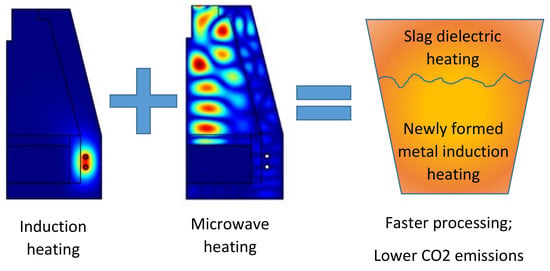
In summary, microwave energy has been broadly used for metallurgy because of the unique and distinguishing advantages of microwave heating. Although there is still much work ahead for advancing the understanding and applications of microwave-assisted metallurgy. One possible solution would be the coupling of different heating techniques, exploiting the advantages of each one of them in processing a special class of materials. For instance, when it comes to molten metal, induction heating is known to provide extremely rapid (and again, volumetric) heating, besides acting as stirring system, for some class of melts. On the other hand, induction heating is not as effective in heating dielectric materials, like the slag which is usually present as a byproduct of the reduction process. Hence, where microwave efficiency drops, induction heating could supply a valuable help and vice versa.
Based on these premises, a new microwave applicator designed to selectively heat the dielectric portion of a heterogeneous and layered load (slag over a molten metal) has been developed using numerical simulation. The applicator is designed in order to be coupled with an induction heating module, to process the newly formed metal. The novelty of this combined approach lies also in the possibility of realizing a complete reduction equipment in the small scale. This would allow to process mineral ores also at the small scale, for instance to serve as auxiliary plants to manufacture “on demand” intermediates for the steelmaking process, like ferroalloys. Ferroalloys are widely used to modify the chemical composition of iron based alloys but in many cases their addition amounts only to a limited percentage of the alloy weight. They possess a high value, especially the low carbon variants, and thus they could benefit of the use of smaller, electrical-powered units, where reduction is performed by metallothermal reactions or using non-carbon based reductants, possibly under vacuum or controlled atmosphere.
2. Numerical Simulation
Numerical simulation has been conducted using the commercial software COMSOL Multiphysics rel. 3.3a. Two sets of simulations have been implemented: a simplified axisymmetric 2D model to investigate possible interactions on the load of induction and microwave heating and a full 3D simulation to design the new microwave applicator. The model definition assumes that, during reduction, the metal in the liquid state tends to flow towards the bottom of the applicator, leaving other non-metallic (or less dense) phases at the surface. This layering of the load during processing suggests that a suitable distribution of the heating sources should be preferentially inductive at the bottom and preferentially dielectric at the top.
2.1. Microwave and Induction Heating of the Load
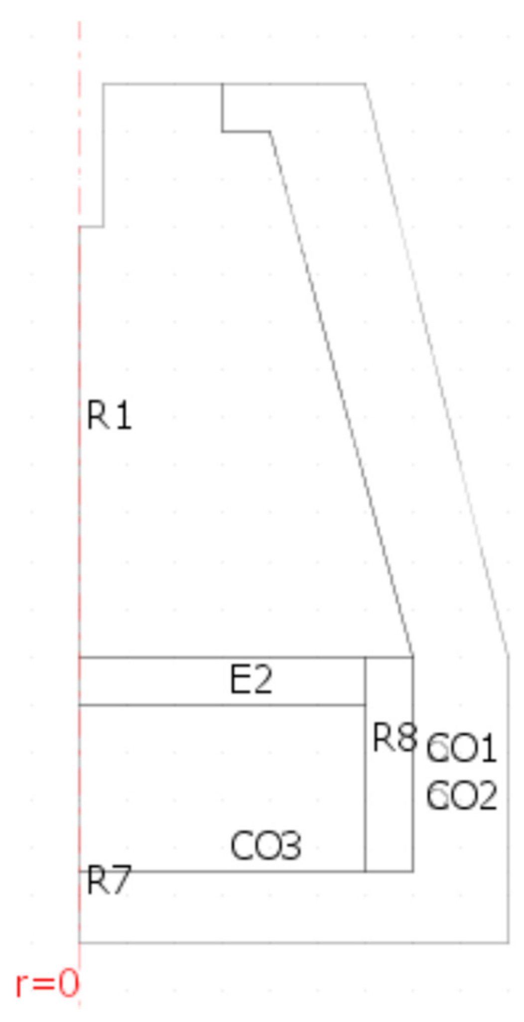
The 2D axisymmetric model geometry is depicted in Figure 1, where the overall external dimensions of the section are 900 (radius) × 1800 (height) mm and the rotation axis is set at r = 0. The Symbols CO1 and CO2 indicate the presence of two windings of the inductor coil and are used only to set boundary conditions (current density) at their surface. The load is made by a crucible, whose side walls are indicated by R8, having an inner radius of 600 mm, filled with liquid metal (CO3) up to 350 mm height, with 100mm of semi-solid slag (E2) on top. A coaxial feed from the top, having 50 mm radius inner conductor, protruding into the applicator for 300 mm has been used to excite the applicator. The remaining symbols and subdomain properties are listed in Table 1.
Meshing was performed using triangular elements, for an overall of 37360 elements, with automatic mesh refining near the inductors, leading to 225151 degrees of freedom, for the fully coupled model. The model is used only to investigate the possibility of differentially heating the load using microwave or induction heating, hence it is a very simplified one, as it does not take into account nor temperature-dependence of the properties of Table 1 neither convection in the molten metal. This allowed to neglect heat transfer and convection, lowering the degrees of freedom down to 149916, for steady state analysis.
The coaxial cable feed (TEM mode) has a predefined power level, Pm, at 915 MHz. The two coils of the inductors have a predefined surface current density, Pi, at 10 KHz. By changing the Pm/Pi ratio, it is possible to investigate different heat generation conditions. Perfect thermal insulation is assumed at the outer boundaries of the model but for this study it is not considered relevant, as the objective is to investigate how power density generation changes in the load and not its temperature raise.
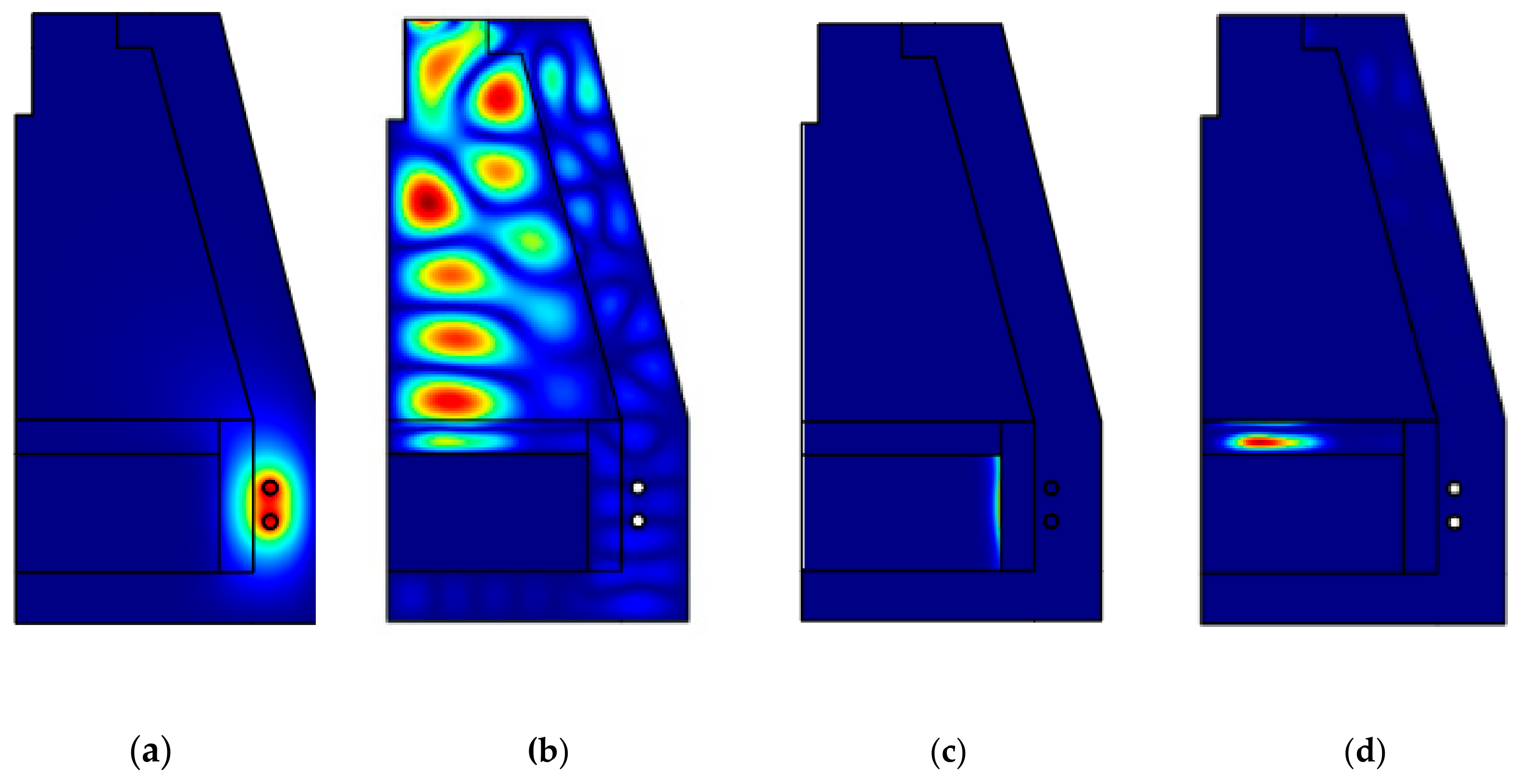
Figure 2 shows the electric field strength and power density in case of pure microwave, pure induction heating, with Pm/Pi = 0.2.
As expected, the use of induction heating tends to selectively heat the conductive regions (molten metal) and the use of microwave heating tends to selectively heat the dielectric regions. The proper choice of a low loss refractory lining allows to avoid significant heating of the lining itself, with most of the power emitted by the microwave source delivered to the load. However, Figure 2d shows that the power density in the lining, especially in the upper part, is not negligible.
Based on these premises, a new microwave applicator designed to selectively heat the dielectric load (i.e., the load positioned in the applicator at the beginning of the reduction process and of the slag, as reduction proceeds). It will be interfaced with an induction-heated crucible positioned at the bottom, as better described in the next section.
2.2. 3D Simulation of a New Microwave Applicator
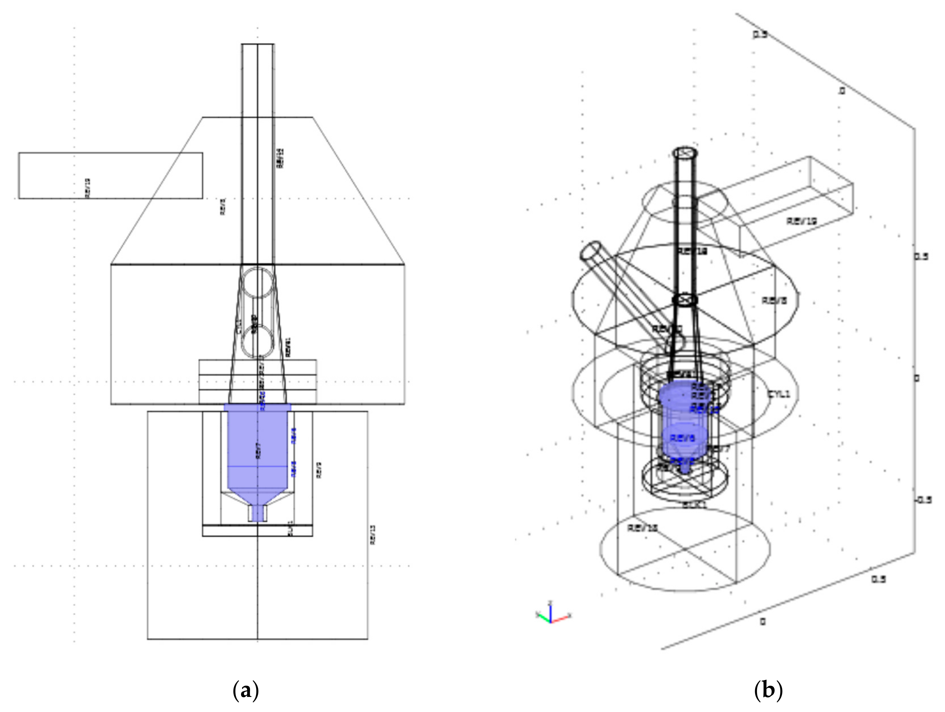
Figure 3 shows the model geometry used for this study, with the load (crucible) highlighted. The upper part is the microwave applicator (top cone and cylinder), while the bottom one, practically positioned up to the same height of the crucible top, is the induction heating applicator (bottom box).
A rectangular waveguide, entering from the left side in Figure 3a, is used to feed the applicator. A commercial waveguide to coaxial transition (not modeled) is positioned at one end of the waveguide and a 3-stubs tuner is installed (not modeled). This setup will allow, on the prototype, to install magnetron or solid state microwave sources. A vertical alumina pipe is used, to load the crucible from the top and to allow for temperature measurements, both by inserting S-type thermocouples (feasible only when the power generation is off) or by optical pyrometers and thermal cameras. Three refractory rings are positioned at the bottom of the microwave applicator, above the crucible top, for impedance matching purposes and to provide auxiliary protection of the cavity walls from the high temperature during processing. A side-positioned metal pipe is used to extract and post-process fumes.
The bottom part of the applicator, the induction heating one, is a modified induction heating furnace of 30 kW power, whose top is closed by a 30 mm thick water cooled metal ring, presenting a hole to allow for microwave reaching the crucible. The crucible dimension was set in agreement with the choice of the slag weight, around 3 kg. The crucible is immersed in a bubble alumina lining and the inductors are positioned coaxially to the crucible itself.
This base geometry has been parameterized in terms of applicator radius (i.e., the radius of the cylinder) and height of the cone upper part, in order to find the most efficient dimensions which could lead to a rapid and homogenous microwave heating of the upper parts of the crucible.
A simplified model has been developed, using the properties indicated in Table 2:
The model is simplified as it neglects temperature dependence of the dielectric properties and as it assumes that some metal has already formed at the bottom of the crucible and a homogenous slag is formed at the top. However, the purpose of this model is to find the optimum configuration able not only to provide high energy efficiency and homogenous power density generation but also to offer possibilities of impedance matching either by using a commercial 3-stubs tuner or by controllably varying the frequency of the microwaves.
Moreover, the model includes two “near to far boxes” (see Supplementary Materials—Figure S1 and S2) which are used to verify that the openings (fume extraction, loading pipe) do not present any significant microwave leakage, for safety related issues. Meshing with tetrahedral cells, using the automatic mesh refinement option of Comsol, led to an overall of 2087137 elements, for 2395018 degrees of freedom.
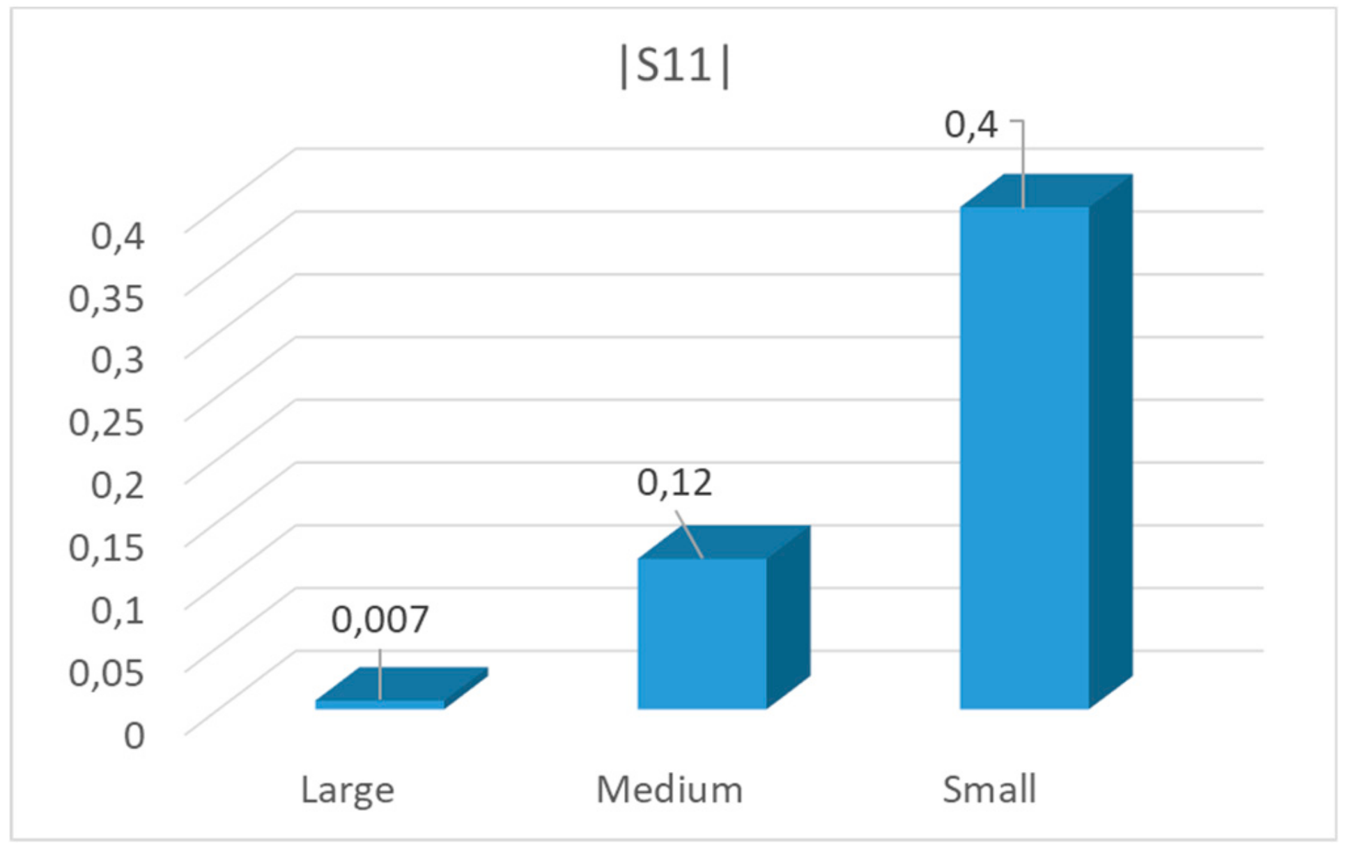
Figure 4 shows the results of this preliminary optimization, in terms of reflection coefficient |S11| at 915 MHz. For high-frequency problems, voltage is not a well-defined entity and it is necessary to define the scattering parameters (S-parameter) in terms of the electric field. To convert an electric field pattern on a port to a scalar complex number corresponding to the voltage in transmission line theory an eigenmode expansion of the electromagnetic fields on the ports needs to be performed. This is done by the RF module of Comsol, where the S-parameter for the mode with a given index (TE10, in case of the rectangular waveguide) is given by multiplying with the conjugate of the mode field for mode with the given index and integrating over the port boundary. [27]
Results indicate that |S11| varies from 0.007 up to 0.4, depending on the applicator dimensions and lining position and dimension. A selection of data for “large,” medium” and “small” applicator is presented in Figure 4, whose parameters are indicated in Table 3. However, the resonance at 915 MHz for the “large” cavity is narrow banded, while the “medium” version presents much larger resonances and a more homogenous power density in the load. Hence, starting from the results of the “medium” applicator, a further optimization has been conducted, leading to the dimensions indicated in Table 4. In this case the optimization has been conducted selecting the solution leading to the lowest integral of |S11| as a function of frequency in the investigated ISM band of 915 ± 15 MHz and not simply looking for the lowest minimum at 915 MHz. This choice is assumed to indicate the presence of multiple minima of this function or of wide banded resonances.
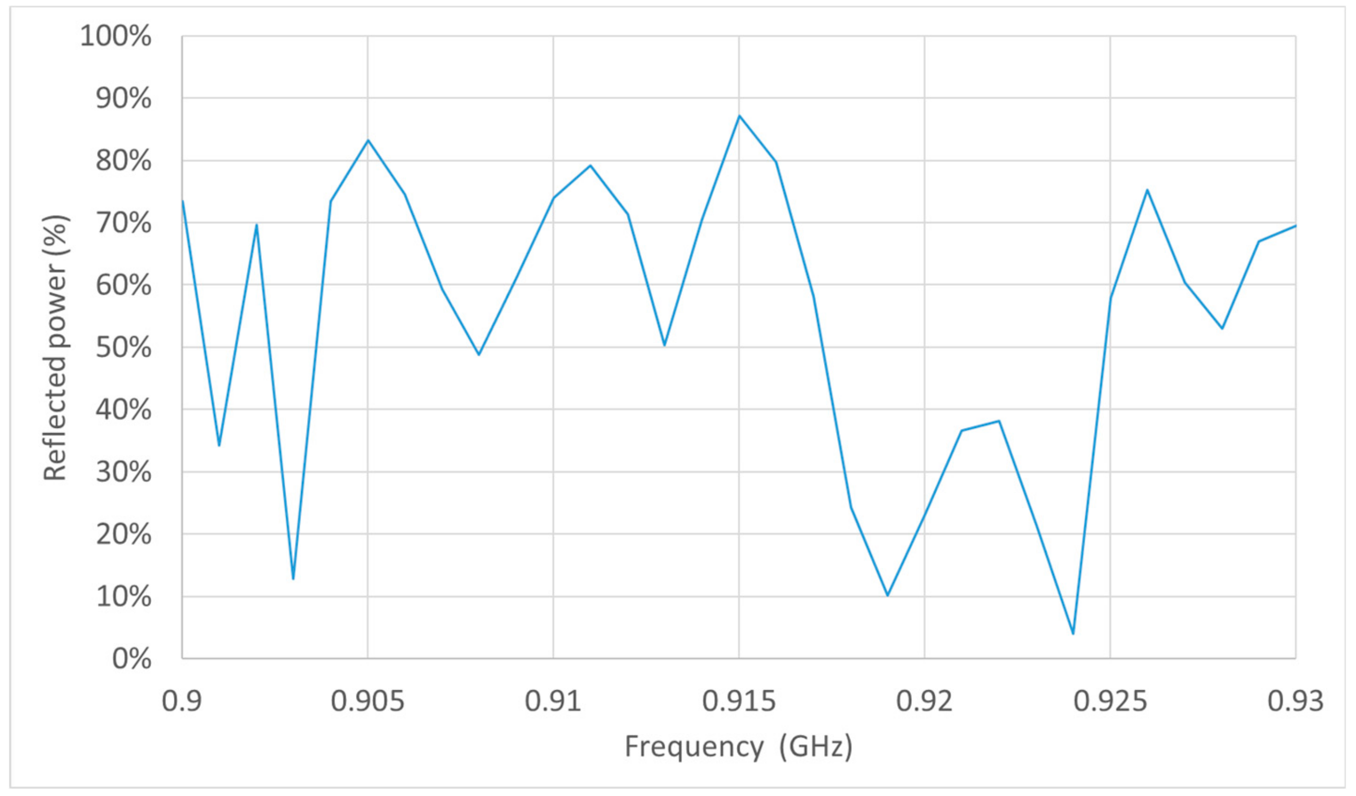
The optimized geometry presents multiple resonances in the investigated frequency range, as shown in Figure 5 in terms of percentage of reflected power (difference between the emitted power and power absorbed in the load). Animations of E-field strength in the cavity are available as Supplementary Materials—Video S1, Video S2, Video S3.
In order to achieve a model useful also in the preliminary testing of the applicator, a simulation using a water load has been performed. In this case both the metal and the slag have been replaced by a load having permittivity of tap water at 40 °C, 73 − i × 3.5, according to Komarov et. al. [28].
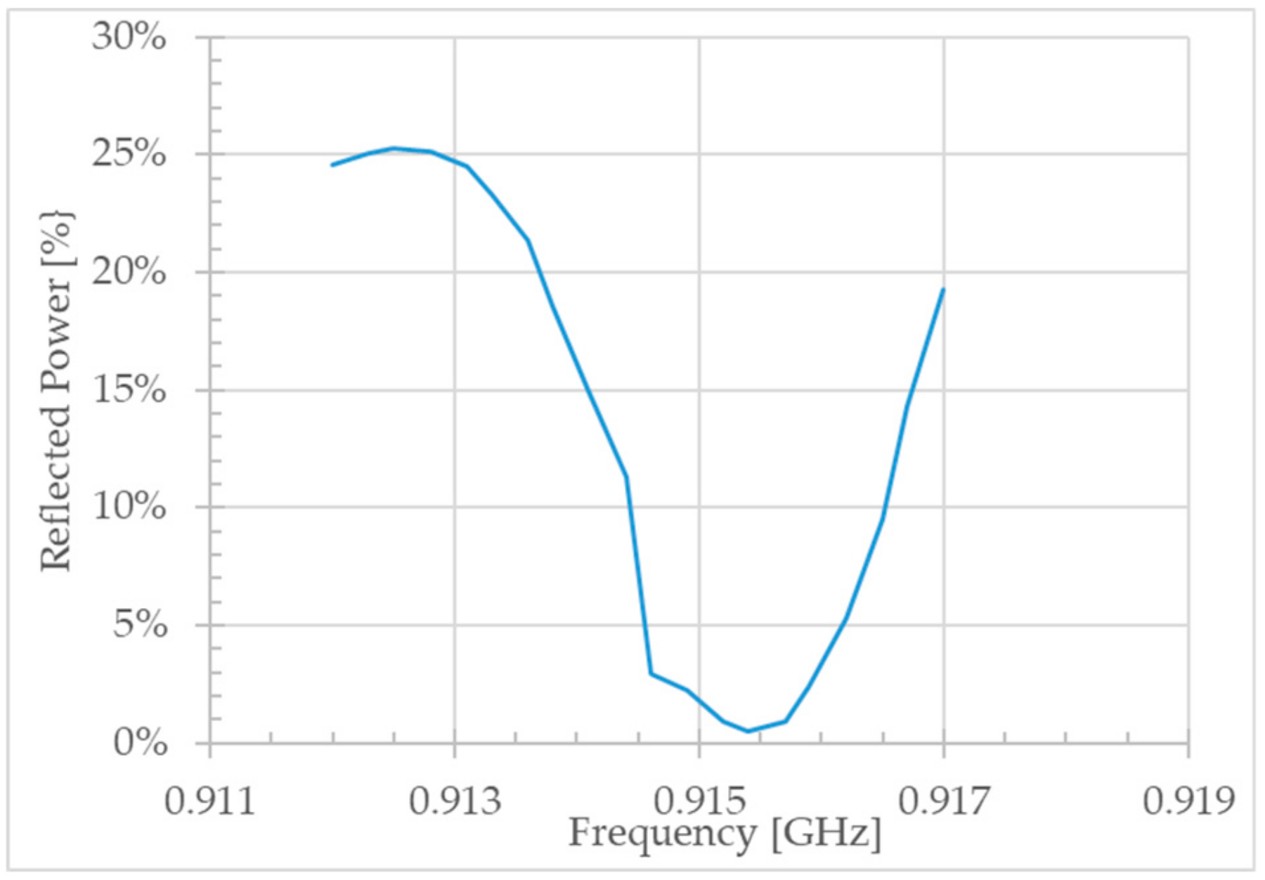
As expected, the use of a load having higher losses allowed to slightly enlarge the resonances as shown in Figure 6.
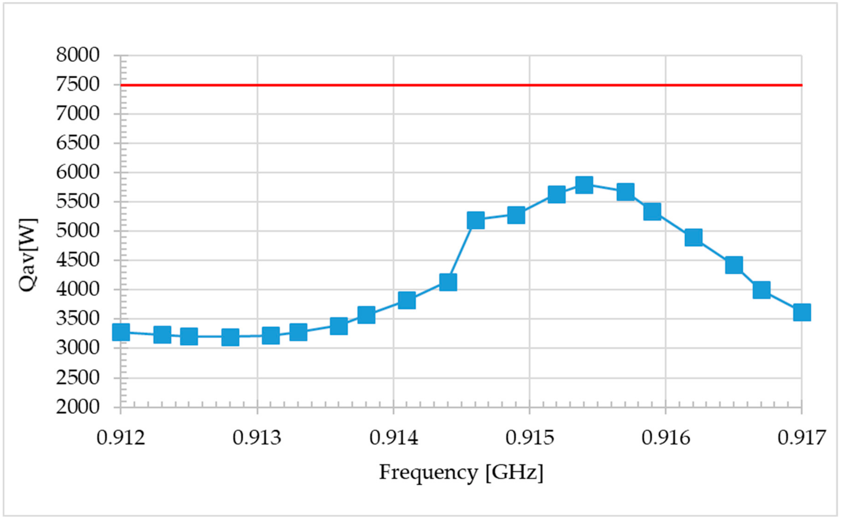
Considering that such low reflected power at 915.2 GHz is given not only by the absorption in the water load but also in the refractory materials and crucibles, defined as lossy, in the model, the volume integration of power density has been used to evaluate the effective amount of power transferred to the load. In this case, a sinusoidal excitation has been set, with an output power of 7500 W. Results, which clearly resemble the ones of Figure 7, show that in the best case almost 6000 W out of 7500 W are dissipated into the water load, the remaining being absorbed by refractories or reflected back to the microwave source. These values obtained on tap water will be used to validate the model in the experimental part.
Considering the “real” load, that is, a molten metal pool on which slag is floating, inside an alumina crucible, the results of Figure 5 evidences some possible resonances and in the framework of maximizing energy efficiency of microwave+induction assisted reduction, only the peaks near or below 10% of reflected power can be considered useful. However, also power generation homogeneity is an objective, hence also other resonances with reflection higher than 10% could help achieving this result, at the cost of a lower efficiency.
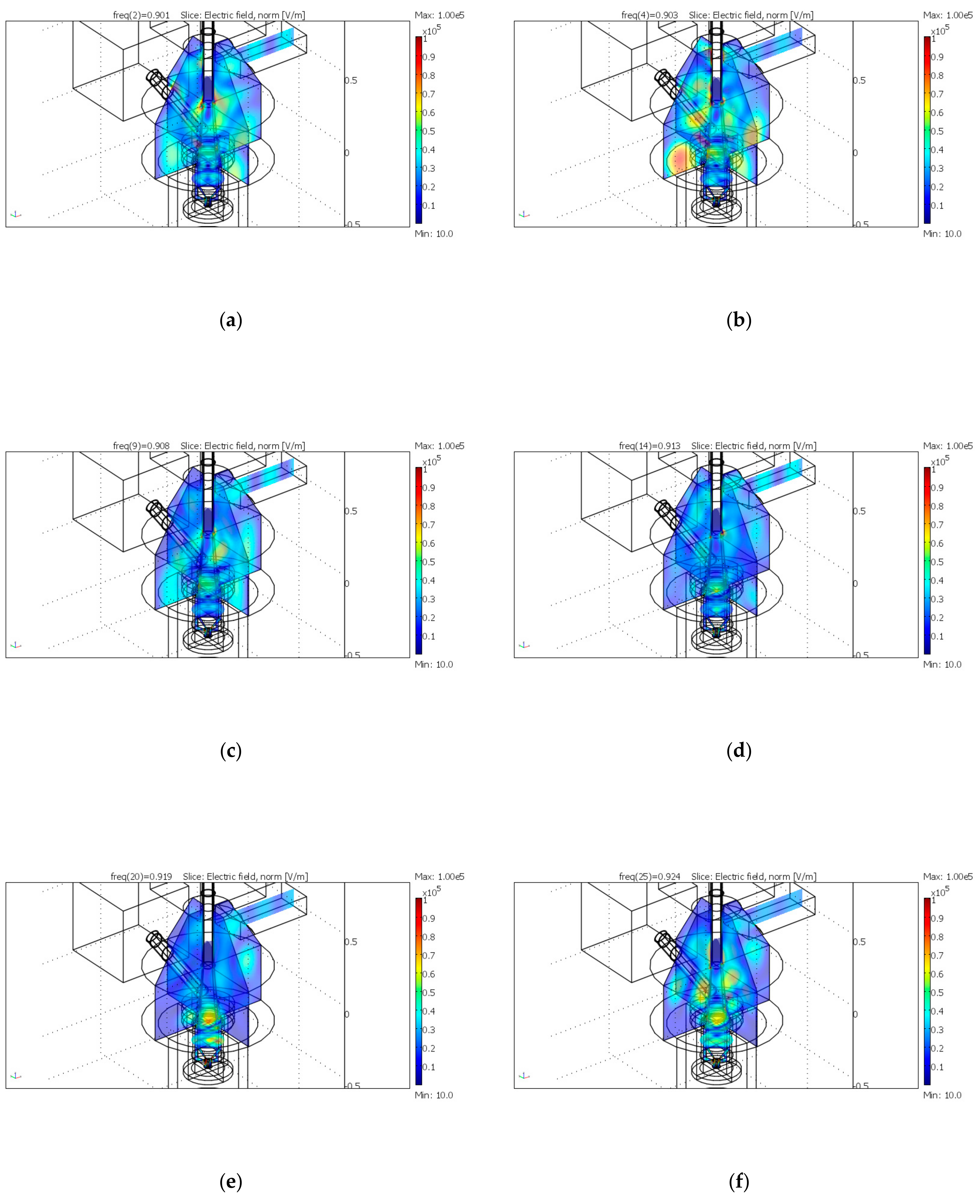
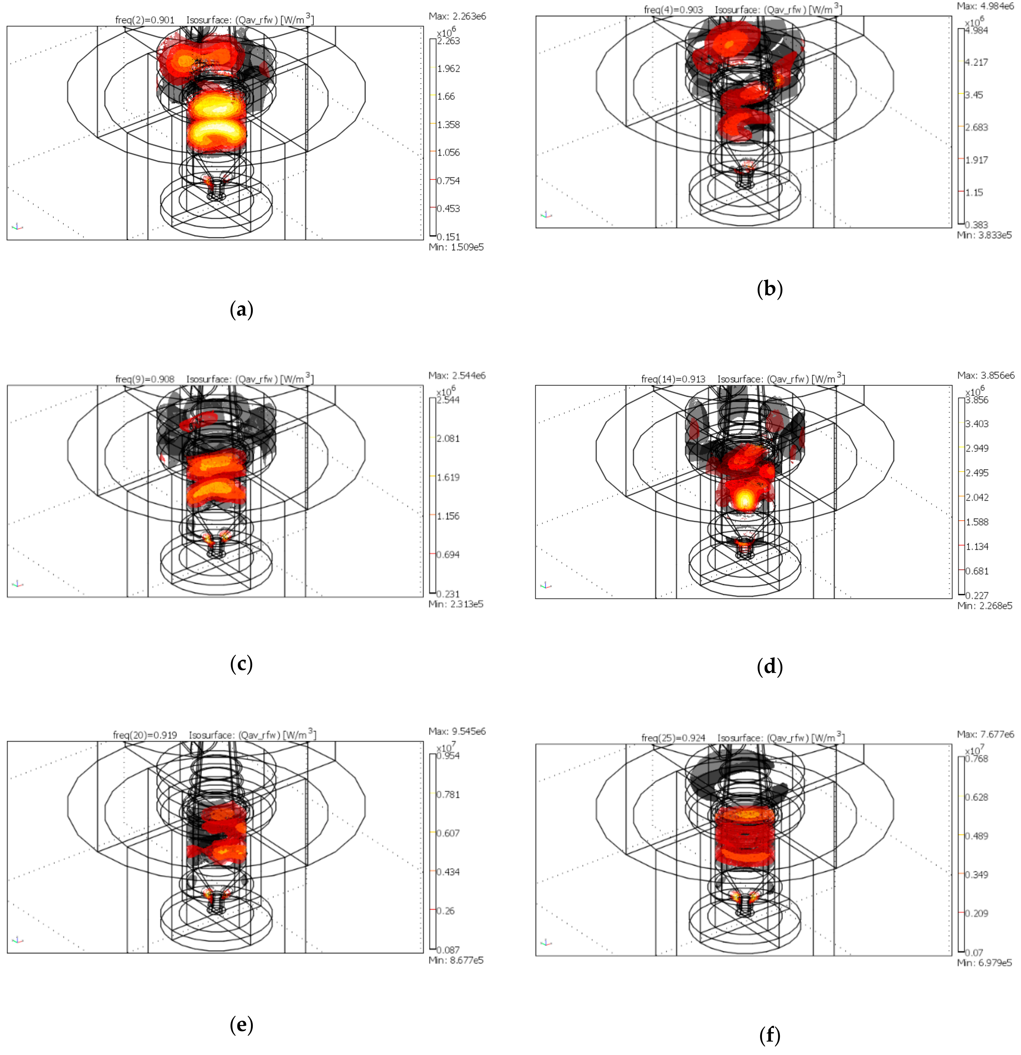
The electric field strength in the microwave applicator and the power density distribution in the load for the 6 more relevant peaks is shown in Figure 8 and Figure 9, using a different scale in order to enhance the differences.
The electric field distribution presents significant variations, by changing the operating frequency, as expected, and in no case microwave leakage occurs trough the input/output ports (pipes), which are designed as circular waveguides well below cutoff conditions.
Results show that, despite the low loss nature of the 3 refractory rings placed above the crucible, a relevant percentage of the power is dissipated in these components, for some frequencies, in agreement with the findings on water load depicted in Figure 8. But, more importantly, it is also evident how the power density distribution changes as a function of the frequency of the emitted microwaves. Hence, by selecting the proper frequency, it is possible to achieve a differential heating of different portion of the loads or to compensate for the possible lack of homogenous heating. This is particularly relevant and it constitutes one of the main advantages in using solid state microwave generators, over other possible combined applicators, like the one mentioned in patent US 6,277,168 B1, where a similar application is devised.
Based on the results of this preliminary optimization, a prototype has been built and tested in the laboratories of the Microwave Application Group (Univ. of Modena and Reggio Emilia).
3. Prototype Testing and Results
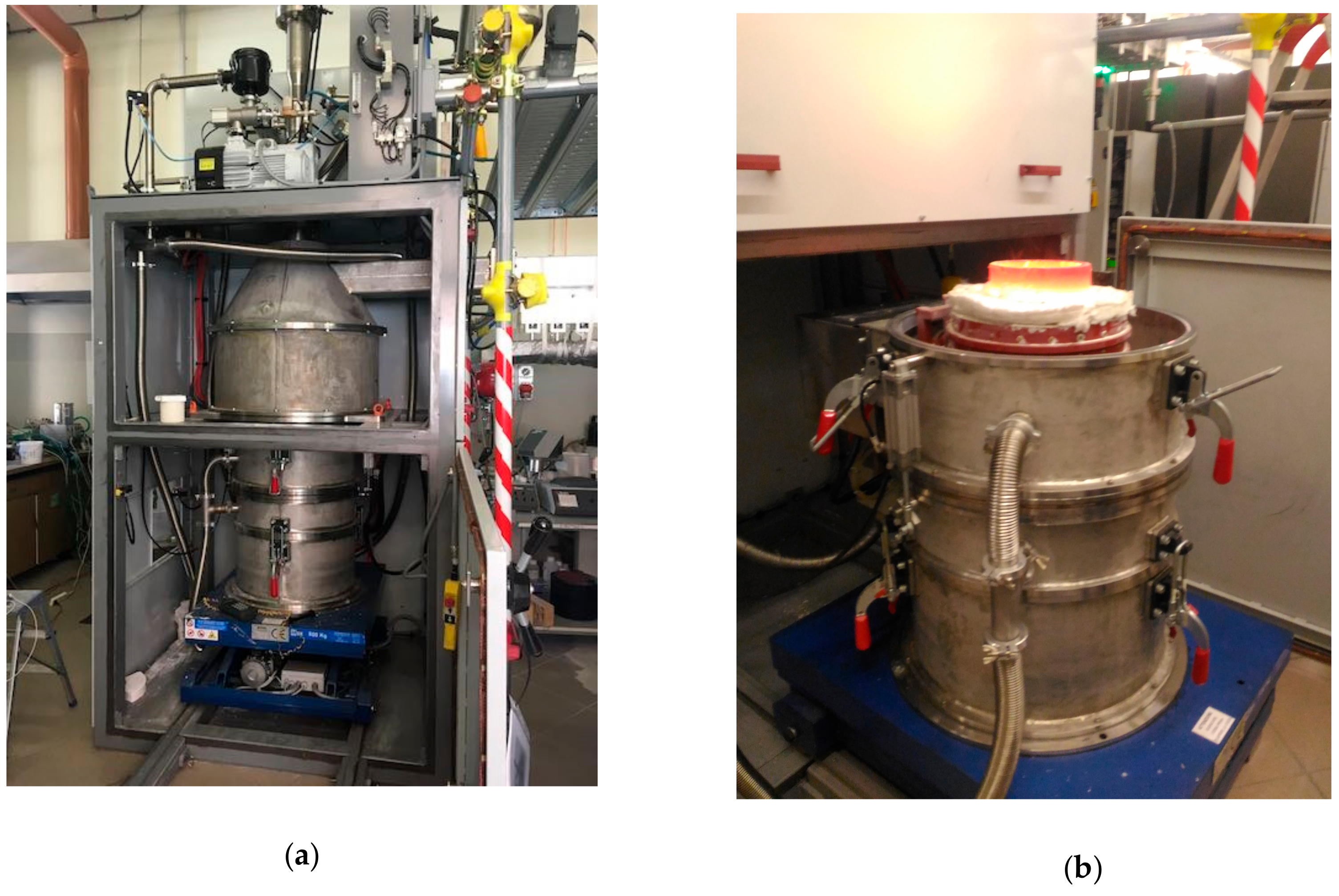
Figure 10 shows the applicator, comprehensive of the induction heating section (bottom part, including an ingot casting station), the microwave heating part and auxiliaries for loading/unloading and gases treatment. The microwave applicator is fed by a new solid state source, 7.5 kW RF power, at 915 ± 15 GHz supplied by MKS Alter, through a coaxial to waveguide transition, a 3-stub tuner and a quartz pressure window. The equipment, as a matter of fact, can be operated both in vacuum and in inert gas overpressure up to 5 atm.
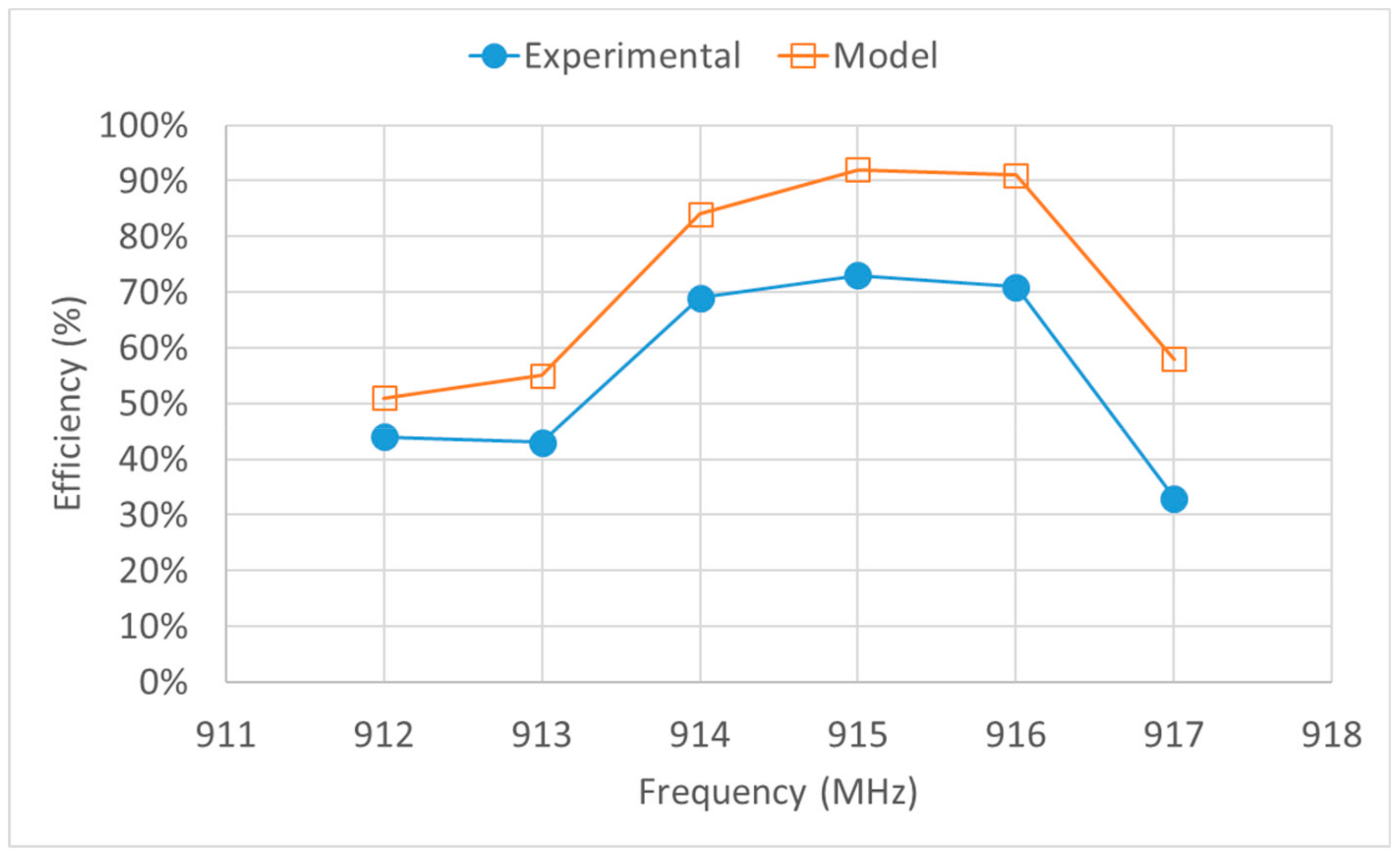
In order to perform a simple and rapid validation of the modelling results, considering the existence in the applicator of multiple loads (the load itself and the refractory materials and crucible), calorimetric testing with a tap water load have been performed, changing the operating frequency of the microwave source. Results, summarized in Figure 11, confirm that, operating on water load and in a limited bandwidth, the applicator provides the highest energy efficiency at 915 MHz.
Despite a good qualitative agreement, the measured efficiency results lower. This can be ascribed to multiple factors, neglected during simulation, ranging from the hypothesis of using perfect electrical conductors for the applicator walls and neglecting heat transfer. As a matter of fact, the here presented numerical simulation addressed only electromagnetic field distribution and power density, not the temperature increase of the load. Such temperature is affected also by heat dissipation towards the surrounding environment, which remains substantially colder. Moreover, no temperature dependence of permittivity of water has been considered in the simplified model, while large variation can occur as temperature increases. This has been experimentally observed also using the “autotuning” function of the solid state generator, with the optimum operating frequency shifting from the initial 915 MHz as heating proceeds.
The applicator was then reverted to the heating of metallurgical products and to test the capabilities of performing a rapid and efficient dielectric heating, some reference loads have been used, amounting to 2500 g of product to be processed. The metallurgical products tested were—iron oxide pellets used for blast furnace (main composition 90% Fe2O3, 6.5% SiO2 + other elements; 3% bentonite as a binder, particle size below 20 mm), electrical arc furnace dust from Rubiera Special Steel S.p.A. (main composition 3.2% C, 32% Fe, 22.1% Zn, 5% CaO, 3% SiO2 + other elements and oxygen, in powder shape unmilled) and the metallurgical slag comes from the production of lead in K.S.S. plant (main composition 19.4% Fe, 15% Zn, 25% CaO, 25% SiO2 + other elements and oxygen, in granules). Table 5 summarizes the results in terms of achievable maximum temperature, measured by a contact thermocouple after 60 s from the turning off of the microwave power, without induction heating. Frequency has been kept fixed during the whole process, using one of the two best frequencies obtained by modelling (see Figure 5).
Results show that using the frequency control option of the solid state generator, extremely low reflected power as measured by the directional coupler of the generator can be achieved, lower than 0.3%. In case of using of the autotuning option, it automatically selected an operating frequency which further minimizes reflections. This is not necessarily the best way to conduct the reduction process, as for some frequencies the refractories dissipate large amounts of power, instead of having it transferred to the load.
For instance, referring to data of Table 5, the EAF dust has been heated with similar input power but in case of frequency of 920 MHz, the average reflected power results slightly higher but the final temperature is 200 °C higher than operating with higher power at 925 MHz. Moreover, as expected for loads experiencing phase transformations and heat losses through the crucible walls and open top, there is a strong nonlinearity between emitted power and final average temperature. This is evident in the case of slag heating, where an almost 2000 W increase of the power output, for a given frequency of 925 MHz, provides only 150 °C increase. These preliminary results suggest that temperature control of the load during heating is mandatory for this kind of equipment and that the coupling of the experimental activity with modelling—tough simplified—can provide a better insight to the process and help explaining some apparent anomalies. This approach will be followed on the next developments with repeated metal-making tests and acquisition of the relevant parameters to evaluate the specific energy consumption and yields.
4. Conclusions and Future Perspectives
Numerical simulation was used to design and optimize the microwave unit of a combined microwave and induction heating furnace for metal making. Simulation results helped identifying different resonances in the 915 MHz ISM band, confirming that heat generation pattern can be controllably varied by shifting the microwave generator frequency within the band. This result is particularly interesting because modern solid state generators allow to control the frequency and hence, in principle, to synthesize the desired heat generation pattern. However this requires the development of much more complex models, including temperature dependence of the materials and taking into account not only phase change but also load shape variations.
Based on numerical simulation results, a 7.5 kW microwave-powered applicator was built and coupled with a 30 kW laboratory scale induction heating furnace. The applicator, enclosed in a Faraday cage was extensively tested for safety issues and used to validate the here proposed simplified numerical model, in case of a reference tap water load. Good agreement between simulated and experimental (calorimetric measurement) results was achieved, despite a slightly lower power efficiency ascribable to wall and heat losses. Future activities will involve the validation of the frequency dependent heat generation pattern, using temperature-activated internal standards dispersed in the load or surface temperature by optical pyrometers. In both cases, it will be an indirect validation of the model, affected by heat transfer but nevertheless it is expected to evidence differences in the early stages of heating, prior to any phase change. The applicator, combined with the induction heating furnace, will then be used to perform microwave assisted reduction experiments, in order to determine the specific energy consumption and compare it with previous results, obtained also by some of the authors, using pure microwave heating (unpublished results on microwave reduction of iron oxide pellets, see Supplementary Materials—Figure S3). In particular, such results were affected by the need for overheating the load in order to generate enough liquid metal and a low viscosity slag. In this framework, the use of the induction heating module is expected to reduce the specific energy consumption and the better control of the atmosphere to lead to lower re-oxidation of the products.
Supplementary Materials
The following are available online at https://www.mdpi.com/2075-4701/10/5/676/s1, Video S1: Electric field strength in the applicator at different frequencies; Video S2: power density in the applicator at different frequencies; Video S3: Power density in a cross sectional slice passing through the load, at different frequencies. Figure S1 and S2: near to far boxes showing no electric field outside the applicator; Figure S3: specific energy consumption during microwave reduction of iron oxide pellets at 2450 MHz.
Author Contributions
Conceptualization, P.V., K.P., S.B. and F.P.; methodology, P.V., E.C., K.P. and F.P; software, P.V., E.C.; validation, P.V., E.C., K.P. and F.P; formal analysis, P.V., E.C. and K.P.; investigation, P.V., E.C., K.P. and F.P.; resources, P.V., K.P. and F.P data P.V., E.C. and K.P.; writing—original draft preparation, P.V. and E.C.; writing—review and editing, P.V., S.B. and K.P.; visualization F.P.; supervision, P.V.; project administration, P.V. and K.P.; funding acquisition, K.P and S.B. All authors have read and agreed to the published version of the manuscript.
Funding
This research was funded by Paul Wurth Italia.
Conflicts of Interest
The authors declare no conflict of interest. The funders had no role in the design of the study but took part in the collection, analyses or interpretation of data and the reviewing of the manuscript and in the decision to publish the results.
References
- Huang, X.; Hwang, J.Y. Method for Direct Metal Making by Microwave Energy. U.S. Patent 6,277,168, 21 August 2001. [Google Scholar]
- Bykov, Y.V.; Rybakov, K.I.; Semenov, V.E. High-temperature microwave processing of materials. J. Phys. D Appl. Phys. 2001, 34, R55–R75. [Google Scholar] [CrossRef]
- Zhong, S.; Geotzman, H.E.; Bleifuss, R.L. Reduction of iron ore with coal by microwave heating. Miner. Metall. Process. 1996, 13, 174–178. [Google Scholar] [CrossRef]
- Rayapudi, V.; Agrawal, S.; Dhawan, N. Optimization of microwave carbothermal reduction for processing of banded hematite jasper ore. Miner. Eng. 2019, 138, 204–214. [Google Scholar] [CrossRef]
- Prasad, R.; Venugopal, R.; Kumarswamidhas, L.A.; Pan, S.K. Effect of microwave heat hardening on microstructure and strength of coke composed iron ore pellet. Mater. Today Proc. 2020. [Google Scholar] [CrossRef]
- Ku, H.S.; Ball, J.A.R.; Siores, E. Review—Microwave processing of materials: Part I. HKIE Trans. Hong Kong Inst. Eng. 2001, 8, 31–37. [Google Scholar] [CrossRef] [Green Version]
- Peng, Z.; Hwang, J.Y. Microwave-assisted metallurgy. Int. Mater. Rev. 2015, 60, 30–63. [Google Scholar] [CrossRef]
- Yoshikawa, N.; Ishizuka, E.; Mashiko, K.; Chan, Y.; Taniguchi, S. Brief review on microwave (MW) heating, its application to iron & steel industry and to the relevant environmental techniques. ISIJ Int. 2007, 47, 523–527. [Google Scholar] [CrossRef] [Green Version]
- Sun, J.; Wang, W.; Yue, Q. Review on microwave-matter interaction fundamentals and efficient microwave-associated heating strategies. Materials 2016, 9, 231. [Google Scholar] [CrossRef] [Green Version]
- Loharkar, P.K.; Ingle, A.; Jhavar, S. Parametric review of microwave-based materials processing and its applications. J. Mater. Res. Technol. 2019, 8, 3306–3326. [Google Scholar] [CrossRef]
- Veronesi, P.; Colombini, E.; Rosa, R.; Leonelli, C.; Garuti, M. Microwave processing of high entropy alloys: A powder metallurgy approach. Chem. Eng. Process. Process Intensif. 2017, 122, 397–403. [Google Scholar] [CrossRef] [Green Version]
- Veronesi, P.; Rosa, R.; Colombini, E.; Leonelli, C. Microwave-Assisted Preparation of High Entropy Alloys. Technologies 2015, 3, 182–197. [Google Scholar] [CrossRef] [Green Version]
- Veronesi, P.; Colombini, E.; Rosa, R.; Leonelli, C.; Rosi, F. Microwave assisted synthesis of Si-modified Mn25FexNi25Cu(50−x) high entropy alloys. Mater. Lett. 2016, 162, 277–280. [Google Scholar] [CrossRef]
- Colombini, E.; Rosa, R.; Trombi, L.; Zadra, M.; Casagrande, A.; Veronesi, P. High entropy alloys obtained by field assisted powder metallurgy route: SPS and microwave heating. Mater. Chem. Phys. 2018, 210, 78–86. [Google Scholar] [CrossRef] [Green Version]
- Leonelli, C.; Poli, G.; Veronesi, P. Simulazione Numerica ed evidenza sperimentale della accelerata formazione di colli durante le fasi iniziali della sinterizzazione assistita da microonde di polveri metalliche. La Metall. Ital. 2007, 4, 27–34. [Google Scholar]
- Ford, J.D.; Pei, D.C.T. High Temperature Chemical Processing via Microwave Absorption. J. Microwave Power 1967, 2, 61–64. [Google Scholar] [CrossRef]
- Roy, R.; Agrawal, D.; Cheng, J.; Gedevanlshvili, S. Full sintering of powdered-metal bodies in a microwave field. Nature 1999, 399, 668–670. [Google Scholar] [CrossRef]
- Veronesi, P.; Rosa, R.; Colombini, E.; Leonelli, C.; Poli, G.; Casagrande, A. Microwave assisted combustion synthesis of non-equilibrium intermetallic compounds. J. Microw. Power Electromagn. Energy 2010, 44, 46–56. [Google Scholar] [CrossRef]
- Rosa, R.; Veronesi, P.V. Functionally Graded Materials Obtained by Combustion Synthesis Techniques: A Review. In Functionally Graded Materials; Reynolds, N.J., Ed.; Published by Nova Science Publishers. Inc.: New York, NY, USA, 2012; pp. 93–121. [Google Scholar]
- Colombini, E.; Rosa, R.; Veronesi, P.; Cavallini, M.; Poli, G.; Leonelli, C. Microwave ignited combustion synthesis as a joining technique for dissimilar materials: Modeling and experimental results. Int. J. Self-Propagating High-Temp. Synth. 2012, 21, 25–31. [Google Scholar] [CrossRef]
- Li, F.; Zhang, M.; Wang, X.D. Applications of microwave in metallurgical processes. Chin. J. Process Eng. 2007, 7, 186–193. [Google Scholar]
- Shaohua, J.; Singh, P.; Jinhui, P.; Nikoloski, A.N.; Chao, L.; Shenghui, G.; Das, R.P.; Libo, Z. Recent developments in the application of microwave energy in process metallurgy at KUST. Miner. Process. Extr. Metall. Rev. 2018, 39, 181–190. [Google Scholar] [CrossRef]
- Bradshaw, S.; Delport, S.; Van Wyk, E. Qualitative measurement of heating uniformity in a multimode microwave cavity. J. Microw. Power Electromagn. Energy 1997, 32, 87–95. [Google Scholar] [CrossRef]
- Ye, L.; Peng, Z.; Wang, L.; Anzulevich, A.; Bychkov, I.; Tang, H.; Rao, M.; Zhang, Y.; Li, G.; Jiang, T. Preparation of core-shell iron ore-biochar composite pellets for microwave reduction. Powder Technol. 2018, 338, 365–375. [Google Scholar] [CrossRef]
- Agrawal, S.; Rayapudi, V.; Dhawan, N. Comparison of microwave and conventional carbothermal reduction of red mud for recovery of iron values. Miner. Eng. 2019, 132, 202–210. [Google Scholar] [CrossRef]
- Komarov, V.V. Handbook of Dielectric and Thermal Properties of Materials at Microwave Frequencies; Artech House Publishers: Boston, MI, USA, 2012. [Google Scholar]
- COMSOL AB. COMSOL Multiphysics® v. 3.3; Stockholm, S., Ed.; COMSOL AB: Stockholm, Sweden, 2006. [Google Scholar]
- Komarov, V.V.; Tang, J. Dielectric permittivity and loss factor of tap water at 915 MHz. Microw. Opt. Technol. Lett. 2004, 42, 419–420. [Google Scholar] [CrossRef]
Figure 1.
2D model geometry of the induction + microwave heating of the load.

Figure 2.
Surface plots of: (a) Electric field strength in case of pure induction heating (max = 82 V/m); (b) Electric filed strength in case of pure microwave heating (max = 9488 V/m); (c) Power density in case of pure induction heating (max = 1.34 × 10⁶ W/m3); (d) Power density in case of pure microwave heating (max = 8.48 × 10⁴ W/m3).

Figure 3.
Model geometry, with highlighted the load (crucible) position: (a) longitudinal cross section; (b) 3D view.
Figure 3.
Model geometry, with highlighted the load (crucible) position: (a) longitudinal cross section; (b) 3D view.

Figure 4.
|S11| for 3 different cavity dimension indicated in Table 3.
Figure 4.
|S11| for 3 different cavity dimension indicated in Table 3.

Figure 5.
Reflected power as a function of frequency, centered on the 915 MHz ISM band.

Figure 6.
Dissipated power in water load as a function of frequencies centered around 915 MHz.

Figure 7.
Volume integral of the power density—i.e., dissipated power in the load alone, as a function of frequency.
Figure 7.
Volume integral of the power density—i.e., dissipated power in the load alone, as a function of frequency.

Figure 8.
Electric field strength distribution in the applicator at the frequency of: (a) 901 MHz; (b) 903 MHz; (c) 908 MHz; (d) 913 MHz; (e) 919 MHz; (f) 924 MHz.
Figure 8.
Electric field strength distribution in the applicator at the frequency of: (a) 901 MHz; (b) 903 MHz; (c) 908 MHz; (d) 913 MHz; (e) 919 MHz; (f) 924 MHz.

Figure 9.
Power density distribution in the load and in the 3 refractory rings at the frequency of: (a) 901 MHz; (b) 903 MHz; (c) 908 MHz; (d) 913 MHz; (e) 919 MHz; (f) 924 MHz.
Figure 9.
Power density distribution in the load and in the 3 refractory rings at the frequency of: (a) 901 MHz; (b) 903 MHz; (c) 908 MHz; (d) 913 MHz; (e) 919 MHz; (f) 924 MHz.

Figure 10.
Prototype (a) with outer Faraday cage removed, showing on the top the microwave applicator fed through the waveguide on the right (b) with hot crucible and induction part removed from the bottom by a shifting mechanism.
Figure 10.
Prototype (a) with outer Faraday cage removed, showing on the top the microwave applicator fed through the waveguide on the right (b) with hot crucible and induction part removed from the bottom by a shifting mechanism.

Figure 11.
Measured dissipated power on the water load (Experimental) vs simulated one (Model).


Table 1.
Subdomain description referred to Figure 1 and relevant properties used in the model: relative permittivity, electrical conductivity, density, thermal conductivity and specific heat. The outer space is assumed to be a Perfect Electric Conductor (PEC). Relative permeability is set at 1.
Table 1.
Subdomain description referred to Figure 1 and relevant properties used in the model: relative permittivity, electrical conductivity, density, thermal conductivity and specific heat. The outer space is assumed to be a Perfect Electric Conductor (PEC). Relative permeability is set at 1.
| Subd. | Name | Material | εr * | σ [S/m] | ρ [kg/m3] | λ [W/mK] | cp [J/kg K] |
|---|---|---|---|---|---|---|---|
| R1 | Inner top | Air | 1 | 0 | 1.29 | 0.026 | 1.01 |
| E2 | Load top | Slag | 5 − i × 0.1 | 0 | 2100 | 2.2 | 710 |
| CO3 | Load bottom | Molten copper | 28571 | 8790 | 28.9 | 390 | |
| R7 | Lining | Refractory | 3.1 − i × 0.01 | 0 | 2200 | 2.5 | 705 |
| R8 | Crucible | Refractory | 3.1 − i × 0.01 | 0 | 2200 | 2.5 | 705 |
| CO1,2 | Inductors | Copper | Used | for | boundary | cond. | |
| Outer | space | PEC | ∞ |
Table 2.
Subdomain description referred to Figure 3 and their relative permittivity. The outer space is assumed to be a Perfect Electric Conductor (PEC).
Table 2.
Subdomain description referred to Figure 3 and their relative permittivity. The outer space is assumed to be a Perfect Electric Conductor (PEC).
| Name | Material | εr* | σ [S/m] |
|---|---|---|---|
| Waveguide | Air | 1 | |
| Applicator (Cyl.+cone) | Air | 13 | |
| Rings | Bubble alumina | 3.1 – i × 0.002 | |
| Vertical pipe | Alumina | 8.7 − i × 0.005 | |
| Crucible | Alumina | 8.7 − i × 0.005 | |
| Crucible lining | Bubble alumina | 3.1 − i × 0.002 | |
| Load top | Slag | 5 − i × 0.1 | |
| Load bottom | Metal (PEC) | ∞ | |
| Outer space | PEC | ∞ |
Table 3.
Applicator relevant dimensions.
| Item | Dimension [mm] | |||||
|---|---|---|---|---|---|---|
| Large | Medium | Small | ||||
| Diameter | Height | Diameter | Height | Diameter | Height | |
| Crucible | 228 | 150 | 228 | 150 | 228 | 150 |
| Cylindrical base (induction) | 620 | 720 | 620 | 620 | 620 | 520 |
| Cylinder (microwave) | 1000 | 500 | 800 | 320 | 600 | 220 |
| Upper cone (microwave) | 1000 | 600 | 800 | 400 | 600 | 320 |
| Feed tube external | 40 | 700 | 50 | 700 | 40 | 450 |
| Feed tube internal | 20 | 700 | 30 | 700 | 20 | 450 |
| Refractory rings | 320 | 120 | 320 | 120 | 320 | 120 |
| Total height | 1820 | 1340 | 1060 | |||
Table 4.
Dimension of optimized cavity.
| Item | Dimension [mm] | |
|---|---|---|
| Large | ||
| Diameter | Height | |
| Crucible | 228 | 150 |
| Cylindrical base (induction) | 620 | 720 |
| Cylinder (microwave) | 810 | 320 |
| Upper cone (microwave) | 810 | 404 |
| Feed tube external | 100 | 700 |
| Feed tube internal | 80 | 700 |
| Refractory rings | 320 | 120 |
Table 5.
Results of preliminary heating tests ad different power levels, for 10 min irradiation in case of iron oxides pellets, electric arc furnace dust mixed with 0.7% coke and metallurgical slag mixed to 23% coke. Autotuning off.
Table 5.
Results of preliminary heating tests ad different power levels, for 10 min irradiation in case of iron oxides pellets, electric arc furnace dust mixed with 0.7% coke and metallurgical slag mixed to 23% coke. Autotuning off.
| Power in [W] | Frequency [MHz] | Reflected Power [W] | Material | Tin [°C] | Tout [°C] |
|---|---|---|---|---|---|
| 4500 | 920 | 38 | Fe2O3 pellets | 15 | Melt |
| 5627 | 924 | 20 | EAF dust + coke | 15 | 1495 |
| 5300 | 919 | 35 | 15 | 1704 | |
| 5424 | 924 | 25 | Slag + coke | 15 | 1589 |
| 7232 | 924 | 20 | 15 | 1743 |
© 2020 by the authors. Licensee MDPI, Basel, Switzerland. This article is an open access article distributed under the terms and conditions of the Creative Commons Attribution (CC BY) license (http://creativecommons.org/licenses/by/4.0/).
Share and Cite
MDPI and ACS Style
Colombini, E.; Papalia, K.; Barozzi, S.; Perugi, F.; Veronesi, P. A Novel Microwave and Induction Heating Applicator for Metal Making: Design and Testing. Metals 2020, 10, 676. https://doi.org/10.3390/met10050676
AMA Style
Colombini E, Papalia K, Barozzi S, Perugi F, Veronesi P. A Novel Microwave and Induction Heating Applicator for Metal Making: Design and Testing. Metals. 2020; 10(5):676. https://doi.org/10.3390/met10050676
Chicago/Turabian StyleColombini, Elena, Katia Papalia, Stefano Barozzi, Francesco Perugi, and Paolo Veronesi. 2020. "A Novel Microwave and Induction Heating Applicator for Metal Making: Design and Testing" Metals 10, no. 5: 676. https://doi.org/10.3390/met10050676
Note that from the first issue of 2016, this journal uses article numbers instead of page numbers. See further details here.